EP2861289B1 - Dispositif de tube nasal - Google Patents
Dispositif de tube nasal Download PDFInfo
- Publication number
- EP2861289B1 EP2861289B1 EP13807038.8A EP13807038A EP2861289B1 EP 2861289 B1 EP2861289 B1 EP 2861289B1 EP 13807038 A EP13807038 A EP 13807038A EP 2861289 B1 EP2861289 B1 EP 2861289B1
- Authority
- EP
- European Patent Office
- Prior art keywords
- nasal tube
- nasal
- tube
- patient
- lumen
- Prior art date
- Legal status (The legal status is an assumption and is not a legal conclusion. Google has not performed a legal analysis and makes no representation as to the accuracy of the status listed.)
- Active
Links
Images


Classifications
-
- A—HUMAN NECESSITIES
- A61—MEDICAL OR VETERINARY SCIENCE; HYGIENE
- A61M—DEVICES FOR INTRODUCING MEDIA INTO, OR ONTO, THE BODY; DEVICES FOR TRANSDUCING BODY MEDIA OR FOR TAKING MEDIA FROM THE BODY; DEVICES FOR PRODUCING OR ENDING SLEEP OR STUPOR
- A61M39/00—Tubes, tube connectors, tube couplings, valves, access sites or the like, specially adapted for medical use
- A61M39/08—Tubes; Storage means specially adapted therefor
-
- A—HUMAN NECESSITIES
- A61—MEDICAL OR VETERINARY SCIENCE; HYGIENE
- A61B—DIAGNOSIS; SURGERY; IDENTIFICATION
- A61B5/00—Measuring for diagnostic purposes; Identification of persons
- A61B5/08—Detecting, measuring or recording devices for evaluating the respiratory organs
- A61B5/082—Evaluation by breath analysis, e.g. determination of the chemical composition of exhaled breath
-
- A—HUMAN NECESSITIES
- A61—MEDICAL OR VETERINARY SCIENCE; HYGIENE
- A61B—DIAGNOSIS; SURGERY; IDENTIFICATION
- A61B5/00—Measuring for diagnostic purposes; Identification of persons
- A61B5/68—Arrangements of detecting, measuring or recording means, e.g. sensors, in relation to patient
- A61B5/6846—Arrangements of detecting, measuring or recording means, e.g. sensors, in relation to patient specially adapted to be brought in contact with an internal body part, i.e. invasive
- A61B5/6847—Arrangements of detecting, measuring or recording means, e.g. sensors, in relation to patient specially adapted to be brought in contact with an internal body part, i.e. invasive mounted on an invasive device
- A61B5/6852—Catheters
-
- A—HUMAN NECESSITIES
- A61—MEDICAL OR VETERINARY SCIENCE; HYGIENE
- A61M—DEVICES FOR INTRODUCING MEDIA INTO, OR ONTO, THE BODY; DEVICES FOR TRANSDUCING BODY MEDIA OR FOR TAKING MEDIA FROM THE BODY; DEVICES FOR PRODUCING OR ENDING SLEEP OR STUPOR
- A61M16/00—Devices for influencing the respiratory system of patients by gas treatment, e.g. mouth-to-mouth respiration; Tracheal tubes
- A61M16/04—Tracheal tubes
- A61M16/0461—Nasoendotracheal tubes
-
- A—HUMAN NECESSITIES
- A61—MEDICAL OR VETERINARY SCIENCE; HYGIENE
- A61M—DEVICES FOR INTRODUCING MEDIA INTO, OR ONTO, THE BODY; DEVICES FOR TRANSDUCING BODY MEDIA OR FOR TAKING MEDIA FROM THE BODY; DEVICES FOR PRODUCING OR ENDING SLEEP OR STUPOR
- A61M16/00—Devices for influencing the respiratory system of patients by gas treatment, e.g. mouth-to-mouth respiration; Tracheal tubes
- A61M16/04—Tracheal tubes
- A61M16/0475—Tracheal tubes having openings in the tube
- A61M16/0477—Tracheal tubes having openings in the tube with incorporated means for delivering or removing fluids
- A61M16/0484—Tracheal tubes having openings in the tube with incorporated means for delivering or removing fluids at the distal end
-
- A—HUMAN NECESSITIES
- A61—MEDICAL OR VETERINARY SCIENCE; HYGIENE
- A61M—DEVICES FOR INTRODUCING MEDIA INTO, OR ONTO, THE BODY; DEVICES FOR TRANSDUCING BODY MEDIA OR FOR TAKING MEDIA FROM THE BODY; DEVICES FOR PRODUCING OR ENDING SLEEP OR STUPOR
- A61M16/00—Devices for influencing the respiratory system of patients by gas treatment, e.g. mouth-to-mouth respiration; Tracheal tubes
- A61M16/04—Tracheal tubes
- A61M16/0486—Multi-lumen tracheal tubes
-
- A—HUMAN NECESSITIES
- A61—MEDICAL OR VETERINARY SCIENCE; HYGIENE
- A61M—DEVICES FOR INTRODUCING MEDIA INTO, OR ONTO, THE BODY; DEVICES FOR TRANSDUCING BODY MEDIA OR FOR TAKING MEDIA FROM THE BODY; DEVICES FOR PRODUCING OR ENDING SLEEP OR STUPOR
- A61M16/00—Devices for influencing the respiratory system of patients by gas treatment, e.g. mouth-to-mouth respiration; Tracheal tubes
- A61M16/04—Tracheal tubes
- A61M16/0488—Mouthpieces; Means for guiding, securing or introducing the tubes
-
- A—HUMAN NECESSITIES
- A61—MEDICAL OR VETERINARY SCIENCE; HYGIENE
- A61M—DEVICES FOR INTRODUCING MEDIA INTO, OR ONTO, THE BODY; DEVICES FOR TRANSDUCING BODY MEDIA OR FOR TAKING MEDIA FROM THE BODY; DEVICES FOR PRODUCING OR ENDING SLEEP OR STUPOR
- A61M16/00—Devices for influencing the respiratory system of patients by gas treatment, e.g. mouth-to-mouth respiration; Tracheal tubes
- A61M16/06—Respiratory or anaesthetic masks
- A61M16/0666—Nasal cannulas or tubing
-
- A—HUMAN NECESSITIES
- A61—MEDICAL OR VETERINARY SCIENCE; HYGIENE
- A61M—DEVICES FOR INTRODUCING MEDIA INTO, OR ONTO, THE BODY; DEVICES FOR TRANSDUCING BODY MEDIA OR FOR TAKING MEDIA FROM THE BODY; DEVICES FOR PRODUCING OR ENDING SLEEP OR STUPOR
- A61M16/00—Devices for influencing the respiratory system of patients by gas treatment, e.g. mouth-to-mouth respiration; Tracheal tubes
- A61M16/06—Respiratory or anaesthetic masks
- A61M16/0683—Holding devices therefor
-
- A—HUMAN NECESSITIES
- A61—MEDICAL OR VETERINARY SCIENCE; HYGIENE
- A61M—DEVICES FOR INTRODUCING MEDIA INTO, OR ONTO, THE BODY; DEVICES FOR TRANSDUCING BODY MEDIA OR FOR TAKING MEDIA FROM THE BODY; DEVICES FOR PRODUCING OR ENDING SLEEP OR STUPOR
- A61M16/00—Devices for influencing the respiratory system of patients by gas treatment, e.g. mouth-to-mouth respiration; Tracheal tubes
- A61M16/08—Bellows; Connecting tubes ; Water traps; Patient circuits
- A61M16/0816—Joints or connectors
- A61M16/0841—Joints or connectors for sampling
- A61M16/085—Gas sampling
-
- A—HUMAN NECESSITIES
- A61—MEDICAL OR VETERINARY SCIENCE; HYGIENE
- A61B—DIAGNOSIS; SURGERY; IDENTIFICATION
- A61B2505/00—Evaluating, monitoring or diagnosing in the context of a particular type of medical care
- A61B2505/05—Surgical care
-
- A—HUMAN NECESSITIES
- A61—MEDICAL OR VETERINARY SCIENCE; HYGIENE
- A61B—DIAGNOSIS; SURGERY; IDENTIFICATION
- A61B5/00—Measuring for diagnostic purposes; Identification of persons
- A61B5/02—Detecting, measuring or recording pulse, heart rate, blood pressure or blood flow; Combined pulse/heart-rate/blood pressure determination; Evaluating a cardiovascular condition not otherwise provided for, e.g. using combinations of techniques provided for in this group with electrocardiography or electroauscultation; Heart catheters for measuring blood pressure
- A61B5/0205—Simultaneously evaluating both cardiovascular conditions and different types of body conditions, e.g. heart and respiratory condition
- A61B5/02055—Simultaneously evaluating both cardiovascular condition and temperature
-
- A—HUMAN NECESSITIES
- A61—MEDICAL OR VETERINARY SCIENCE; HYGIENE
- A61B—DIAGNOSIS; SURGERY; IDENTIFICATION
- A61B5/00—Measuring for diagnostic purposes; Identification of persons
- A61B5/08—Detecting, measuring or recording devices for evaluating the respiratory organs
- A61B5/083—Measuring rate of metabolism by using breath test, e.g. measuring rate of oxygen consumption
- A61B5/0836—Measuring rate of CO2 production
-
- A—HUMAN NECESSITIES
- A61—MEDICAL OR VETERINARY SCIENCE; HYGIENE
- A61M—DEVICES FOR INTRODUCING MEDIA INTO, OR ONTO, THE BODY; DEVICES FOR TRANSDUCING BODY MEDIA OR FOR TAKING MEDIA FROM THE BODY; DEVICES FOR PRODUCING OR ENDING SLEEP OR STUPOR
- A61M16/00—Devices for influencing the respiratory system of patients by gas treatment, e.g. mouth-to-mouth respiration; Tracheal tubes
- A61M16/10—Preparation of respiratory gases or vapours
- A61M16/1005—Preparation of respiratory gases or vapours with O2 features or with parameter measurement
- A61M2016/102—Measuring a parameter of the content of the delivered gas
- A61M2016/1025—Measuring a parameter of the content of the delivered gas the O2 concentration
-
- A—HUMAN NECESSITIES
- A61—MEDICAL OR VETERINARY SCIENCE; HYGIENE
- A61M—DEVICES FOR INTRODUCING MEDIA INTO, OR ONTO, THE BODY; DEVICES FOR TRANSDUCING BODY MEDIA OR FOR TAKING MEDIA FROM THE BODY; DEVICES FOR PRODUCING OR ENDING SLEEP OR STUPOR
- A61M16/00—Devices for influencing the respiratory system of patients by gas treatment, e.g. mouth-to-mouth respiration; Tracheal tubes
- A61M16/10—Preparation of respiratory gases or vapours
- A61M16/1005—Preparation of respiratory gases or vapours with O2 features or with parameter measurement
- A61M2016/102—Measuring a parameter of the content of the delivered gas
- A61M2016/103—Measuring a parameter of the content of the delivered gas the CO2 concentration
-
- A—HUMAN NECESSITIES
- A61—MEDICAL OR VETERINARY SCIENCE; HYGIENE
- A61M—DEVICES FOR INTRODUCING MEDIA INTO, OR ONTO, THE BODY; DEVICES FOR TRANSDUCING BODY MEDIA OR FOR TAKING MEDIA FROM THE BODY; DEVICES FOR PRODUCING OR ENDING SLEEP OR STUPOR
- A61M16/00—Devices for influencing the respiratory system of patients by gas treatment, e.g. mouth-to-mouth respiration; Tracheal tubes
- A61M16/10—Preparation of respiratory gases or vapours
- A61M16/1005—Preparation of respiratory gases or vapours with O2 features or with parameter measurement
- A61M2016/102—Measuring a parameter of the content of the delivered gas
- A61M2016/1035—Measuring a parameter of the content of the delivered gas the anaesthetic agent concentration
-
- A—HUMAN NECESSITIES
- A61—MEDICAL OR VETERINARY SCIENCE; HYGIENE
- A61M—DEVICES FOR INTRODUCING MEDIA INTO, OR ONTO, THE BODY; DEVICES FOR TRANSDUCING BODY MEDIA OR FOR TAKING MEDIA FROM THE BODY; DEVICES FOR PRODUCING OR ENDING SLEEP OR STUPOR
- A61M2202/00—Special media to be introduced, removed or treated
- A61M2202/02—Gases
- A61M2202/0208—Oxygen
-
- A—HUMAN NECESSITIES
- A61—MEDICAL OR VETERINARY SCIENCE; HYGIENE
- A61M—DEVICES FOR INTRODUCING MEDIA INTO, OR ONTO, THE BODY; DEVICES FOR TRANSDUCING BODY MEDIA OR FOR TAKING MEDIA FROM THE BODY; DEVICES FOR PRODUCING OR ENDING SLEEP OR STUPOR
- A61M2210/00—Anatomical parts of the body
- A61M2210/06—Head
- A61M2210/0618—Nose
-
- A—HUMAN NECESSITIES
- A61—MEDICAL OR VETERINARY SCIENCE; HYGIENE
- A61M—DEVICES FOR INTRODUCING MEDIA INTO, OR ONTO, THE BODY; DEVICES FOR TRANSDUCING BODY MEDIA OR FOR TAKING MEDIA FROM THE BODY; DEVICES FOR PRODUCING OR ENDING SLEEP OR STUPOR
- A61M2230/00—Measuring parameters of the user
- A61M2230/40—Respiratory characteristics
- A61M2230/43—Composition of exhalation
- A61M2230/432—Composition of exhalation partial CO2 pressure (P-CO2)
-
- A—HUMAN NECESSITIES
- A61—MEDICAL OR VETERINARY SCIENCE; HYGIENE
- A61M—DEVICES FOR INTRODUCING MEDIA INTO, OR ONTO, THE BODY; DEVICES FOR TRANSDUCING BODY MEDIA OR FOR TAKING MEDIA FROM THE BODY; DEVICES FOR PRODUCING OR ENDING SLEEP OR STUPOR
- A61M2230/00—Measuring parameters of the user
- A61M2230/40—Respiratory characteristics
- A61M2230/43—Composition of exhalation
- A61M2230/435—Composition of exhalation partial O2 pressure (P-O2)
-
- A—HUMAN NECESSITIES
- A61—MEDICAL OR VETERINARY SCIENCE; HYGIENE
- A61M—DEVICES FOR INTRODUCING MEDIA INTO, OR ONTO, THE BODY; DEVICES FOR TRANSDUCING BODY MEDIA OR FOR TAKING MEDIA FROM THE BODY; DEVICES FOR PRODUCING OR ENDING SLEEP OR STUPOR
- A61M2230/00—Measuring parameters of the user
- A61M2230/40—Respiratory characteristics
- A61M2230/43—Composition of exhalation
- A61M2230/437—Composition of exhalation the anaesthetic agent concentration
Definitions
- nasal tubes used in medicine to treat various conditions. These nasal tubes generally enter through a nostril and travel within the pharyngeal spaces of the patient to their respective destinations. The travel path, destination, tube termination, and function of the nasal tube may vary. For example, a nasogastic tube enters through the nose, terminates in the gut-tube pathway, and delivers nutrients for digestion. A nasopharyngeal airway, also known as an NPA or a nasal trumpet, enters through the nose, terminates near the laryngopharynx, and creates a passive patent airway.
- NPA nasopharyngeal airway
- nasal catheters are often used to monitor patients under general anesthesia.
- nasal catheters are generally inserted through the nose of the patient and terminate in the nasopharyngeal space to deliver oxygen to the patient or monitor the patient's expiration of carbon dioxide during surgery.
- ASA American Society of Anesthesiologists
- the US patent application EP 5 185 005 A discloses a nasogastric tube anchor, and a method of its use employing a bridle which passes through the patient's nostrils and nasopharynx, the ends of the bridle being fastened to a nasogastric tube exterior to the patient's nose to anchor said tube against undesired movement relative to the patient's nostril.
- the invention is defined by the appended claims.
- the present application discloses nasal tube devices, methods for placing and securing a nasal tube to a patient, as well as adapters and connectors for a nasal tube.
- the nasal tube device comprises a nasal tube having a proximal portion, a distal portion, and one or more lumens.
- a securing device is attached to the proximal portion of the nasal tube and is configured to attach a flexible line of a retention system to the nasal tube.
- the nasal tube device comprises a nasal tube having a proximal portion, a distal portion, a retention flange, and one or more lumens
- the retention flange comprises one or more openings for attaching a flexible line of a retention system to the nasal tube.
- the method of placing and securing a nasal tube to a patient comprises utilizing a nasal tube device having a nasal tube attached to a retention system.
- the retention system comprises a flexible line attached to the nasal tube.
- the flexible line is pulled around the vomer bone of a patient.
- the distal end of the nasal tube is simultaneously inserted into a first nostril of the patient as the flexible line is being pulled around the vomer bone.
- the distal end of the nasal tube is positioned in a pharyngeal space of the patient.
- the flexible line is secured around the vomer bone by attaching the flexible line to a proximal portion of the nasal tube.
- the nasal tube device comprises a nasal tube having a proximal portion, a distal portion, and a delivery lumen extending from the proximal portion to an opening in the outer surface of the nasal tube.
- the delivery lumen is configured to receive a connector attached to a flexible line of a retention system.
- the method of placing and securing a nasal tube to a patient comprises utilizing a nasal tube device comprsing a nasal tube having a proximal portion, a distal portion, and a delivery lumen extending from the proximal portion to a delivery window.
- the delivery lumen is configured to receive a connector attached to a flexible line of a retention system.
- the distal end of the nasal tube is inserted into a first nostril of a patient and positioned in a pharyngeal space of the patient.
- the connector attached to the flexible line is deployed out the delivery window.
- the flexible line is pulled through the delivery lumen, around the vomer bone of the patient, and out the second nostril of the patient.
- the flexible line is secured around the vomer bone by attaching the flexible line to the proximal portion of the nasal tube.
- the adapter for a nasal tube comprises a first end having a first port and a second port. Each of the first and second ports of the first end are configured for receipt in a lumen of a nasal tube.
- a second end of the adapter has a first port in fluid communication with the first port of the first end and a second port in fluid communication with the second port of the first end. Each of the first and second ports of the second end are configured for removable connection to a medical tube.
- the nasal tube device comprises a nasal tube having a proximal portion, a distal portion, and a lumen extending from the proximal portion to the distal portion of the nasal tube.
- a securing device is attached to the proximal portion of the nasal tube. The securing device is configured to selectively compress the proximal portion of the nasal tube.
- One or more medical tubes are disposed in the lumen of the nasal tube. The one or more medical tubes are selectively secured in the lumen with the securing device.
- nasal tube devices include any tube that may be inserted through the nose of a patient for a medical purpose.
- a nasal tube device of the present application may be used as a secure nasal tube for airway management, an anesthesiology monitoring device, a delivery port for medical tubes, wires, or instruments, and/or an oxygen delivery device.
- the present application also discloses methods for placing and securing a nasal tube to a patient, as well as adapters and connectors for a nasal tube.
- the nasal tube device of the present application may include a variety of nasal tube types for nearly any medical purpose.
- the nasal tube may be designed to terminate in the pharyngeal spaces of the patient, such as the oropharyngeal or largyngopharyngeal space of the patient.
- the nasal tube may be designed to extend into the esophagus of the patient and terminate in the alimentary tract to aid in nutrient delivery, drug delivery, endoscopy, decompression, etc.
- the nasal tube may also be designed to terminate in the bronchi or the lungs.
- the nasal tube may be a variety of sizes for various applications, such as biopsy in both adult and pediatric populations.
- the nasal tube may be fitted with an inflatable balloon at or near its distal end to facilitate retention of the nasal tube in the patient. Further, the inflatable balloon may be configured to move the tongue away from the distal end of the nasal tube and/or prohibit obstruction of the nasal tube.
- the nasal tube device of the present application may also comprise multiple lumens and/or may bifurcate and pass simultaneously into the esophagus and trachea. Further, the nasal tube device may be capable of passing liquids, air, drugs, or medical instruments, in addition to the delivery of a retention system. The nasal tube device may also function as an aid to monitor conscious sedation anesthesia. The nasal tube device may function passively as a secure nasopharyngeal airway for emergencies or as a part of haemostatic post-op care to maintain airway patency. Further, the nasal tube device may be used to deliver positive pressure ventilation.
- the nasal tube device of the present application comprises a combined nasal tube and nasal tube retention system.
- the retention system is attached to the nasal tube to facilitate placement and securement of the nasal tube to the patient.
- the nasal tube is configured to deliver at least a portion of the retention system into the appropriate pharyngeal space to secure the nasal tube to the patient.
- the nasal tube device of the present application provides numerous advantages over a separate nasal tube and retention systems. For example, the speed of the overall procedure to establish a secure nasal tube is increased by using the nasal tube device. This is particularly important when a patient's airway is compromised, but also has implications for patient comfort as well as ease of the procedure. Further, a combined nasal tube and nasal tube retention system decreases insult from insertion devices. For example, with fewer devices and decreased procedural time, tissue trauma and irritation associated with nasal tube and retention system placement is reduced. Additionally, fewer device insertions correlate with fewer potential procedural failure modes.
- the nasal tube device of the present application is configured to be used as a secure nasal tube for airway management.
- the nasal tube device may comprise a nasal tube that terminates in the nasopharyngeal space of the patient.
- the nasal tube comprises a plurality of lumens.
- a first lumen is configured to provide a secure passive airway for the patient and a second lumen is configured to deliver at least a portion of a retention system into the appropriate pharyngeal space to secure the nasal tube to the patient.
- the nasal tube may also comprise one or more other lumens.
- one or more lumens of the nasal tube may be configured to pass liquids, air, drugs, or medical instruments.
- one or more lumens of the nasal tube may be configured to deliver oxygen to the patient or monitor the patient's expiration of carbon dioxide.
- the nasal tube device may be configured as a combined secure nasal tube for airway management and anesthesiology monitoring/oxygen delivery device.
- the nasal tube device of the present application is configured to be used as an anesthesiology monitoring/oxygen delivery device.
- the nasal tube device comprises a nasal tube that terminates in the nasopharyngeal space of the patient.
- the nasal tube has a plurality of medical tubes secured within a lumen of the nasal tube.
- a first tube may be configured to deliver oxygen to the patient and a second tube may be configured for physiological monitoring of the patient, such as, for example, sampling or monitoring inspired or expired gases (e.g., oxygen, carbon dioxide, or inhalational anesthetic agents) or oxygen saturation of the blood.
- the nasal tube may comprise a delivery lumen configured to deliver at least a portion of a nasal tube retention system into the appropriate pharyngeal space to secure the nasal tube to the patient.
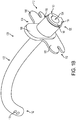
- FIGS 1A-1D illustrate a nasal tube device 100 according to an embodiment of the present application.
- the nasal tube device 100 comprises a nasal tube 102, a retention flange 104, and a securing device 110.
- the nasal tube 102 forms the body of the device 100 and has a proximal end 130 and a distal end 132.
- the nasal tube 102 comprises a single lumen 134 extending from the proximal end 130 to the distal end 132 of the tube.
- the nasal tube 102 may comprise a plurality of lumens, .e.g., one, two, three, four or more lumens, that may or may not extend from the proximal end 130 to the distal end 132 of the nasal tube.
- FIGS 2A-3 illustrate the nasal tube device 100 attached to an exemplary retention system 200.
- the retention system 200 comprises a bridle line 208, a catheter 202 having a first connector 206 at a distal end, and a connecting member 260 having a second connector 262 at a distal end.
- the bridle line 208 is attached to the catheter 202 and the nasal tube device 100.
- the first and second connectors 206 and 262 may be a variety of devices or fasteners configured to connect or otherwise attach together, e.g., when touched together or when placed in close proximity to one another.
- the first and second connectors 206 and 262 are magnets that attach together when placed in proximity to one another.
- the bridle line 208 is threaded through an opening 114 in the retention flange 104 and is knotted to prohibit removal of the line from the nasal tube device 100.
- the bridle line 208 may be attached near the proximal end 130 of the nasal tube 102 by threading the line through a hole in the nasal tube and knotting an end of the line to prohibit removal of the line from the nasal tube device 100.
- the bridle line 208 may also be tied such that a portion or tail of the line extends from the proximal end 130 of the nasal tube 102.
- the bridle line 208 may be attached to the nasal tube device 100 in a variety of other ways, such as, for example, with one or more ties, elastic bands, tape, glue or other adhesive, heat shrink tubing, clips or other fasteners or retainers.
- the bridle line 208 may be attached to the nasal tube 102 with an adhesive and/or heat shrink tubing.
- the bridle line 208 may be attached to one or more tubes extending from the lumen 134 of the nasal tube 102, such as, for example, oxygen and carbon dioxide tubes (e.g., with a clip, adhesive and/or heat shrink tubing).
- the bridle line 208 may also be overmolded with the nasal tube 102 to attach the line to the nasal tube device 100.
- One exemplary method of placing and securing the nasal tube device 100 to a patient includes inserting the distal end of the catheter 202 into a first nostril of the patient and the distal end of the connecting member 260 into a second nostril of the patient.
- the pathways of the two nostrils travel substantially parallel to one another until they terminate into the nasopharnyx 304 (see Figure 3 ).
- the distal ends of the catheter 202 and the connecting member 260 are advanced into the nasopharnyx 304.
- the first connector 206 of the catheter 202 meets the second connector 262 of the connecting member 260 in the nasopharnyx 304 to establish a connection.
- the first and second connectors are magnets that attach together when placed in proximity to one another.
- the connecting member 260 is retracted out of the second nostril. Retraction of the connecting member 260 pulls the catheter 202 and the bridle line 208 around the posterior free edge of the vomer 302 ( Figure 3 ) above the palate and bordering the anterior portion of the nasopharnyx 304.
- the nasal tube 102 is advanced into the first nostril of the patient and positioned such that the distal end 132 of the nasal tube terminates in a pharyngeal space of the patient, such as for example, the oropharyngeal or largyngopharyngeal space of the patient.
- an elongated member such as a flexible wire, is used with the catheter 202 to facilitate delivery and placement of the first connector 206 into the nasopharnyx 304 or pharyngeal space of the patient.
- the elongated member is removed from the catheter 202.
- the elongated member is inserted through an opening in the proximal end of the catheter 202.
- the elongated member may comprise a wire that extends into the catheter 202.
- the elongated member may also extend substantially the entire length of the catheter 202 and abut the first connector 206.
- the wire is generally more rigid than the catheter 202, yet flexible and resilient such that it may be bent to travel through the nostril and nasal passages of the patient and into the nasopharnyx.
- the connecting member 260 may include bends or twists to facilitate connection of the second connector 262 with the first connector 206 of the catheter 202 in the nasopharnyx 304, such as by rotating the connecting member in the nose.
- the nasal tube device 100 eliminates a step in the overall placement and securement procedure for the nasal tube. For example, when a separate nasal tube and nasal tube retention system is used, the bridle line of the retention system is first routed around the vomer 302 of the patient and then the nasal tube is placed over the bridle line. If adequate tension is not maintained on the bridle line during placement of the nasal tube, the line may become dislodged or pulled out of position. The nasal tube device 100 eliminates this step of placing the nasal tube over the bridle line. Further, the nasal tube device 100 of the present application permits the nasal tube 102 to be inserted with anesthesia lines, such as oxygen and carbon dioxide lines, already placed inside the lumen 134 of the nasal tube.
- anesthesia lines such as oxygen and carbon dioxide lines
- the bridle line 208 of the retention system 200 may be a variety of members that are flexible or semi rigid such that they may be wrapped around the vomer bone 302 and extend out a nostril of the patient.
- the bridle line 208 may comprise one or more pieces of fabric (e.g., an umbilical tape or string), cord, or tubing.
- the bridle line 208 may be fiber reinforced or elastomeric, and may be configured such that it does not excessively elongate to prohibit unwanted movement of the nasal tube 102 relative to the patient.
- the bridle line 208, the catheter 202, and/or the first connector 206 may be integrally formed as a unitary component of the retention system 200.
- the bridle line 208 and the catheter 202 may be formed as a single member that is flexible or semi rigid such that it may be wrapped around the vomer bone 302 and extend out a nostril of the patient.
- Figure 3 illustrates the nasal tube device 100 in position and secured to a patient with the bridle line 208 wrapped around the vomer 302.
- the distal end 132 of the nasal tube 102 terminates in the oropharyngeal space 306 of the patient.
- the distal end 132 of the nasal tube 102 may terminate in the largyngopharyngeal space of the patient or may extend into the esophagus of the patient and terminate in the alimentary tract to aid in nutrient delivery, drug delivery, endoscopy, decompression, etc.
- the bridle line 208 extends from the retention flange 104, through the first nostril, around the vomer 302, and out the second nostril of the patient.
- the first and second portions of the bridle line 208 extending from the nostrils may be attached to the nasal tube device 100 using the retention flange 104 and/or the securing device 110.
- the securing device 110 is capable of receiving the bridle line 208 for securing the nasal tube device 100 to the patient.
- the type and/or size of the nasal tube 102 may vary depending on a variety of factors, such as the medical purpose of the device and/or the size of the patient.
- the nasal tube 102 is an NPA or nasal trumpet that facilitates the introduction of anesthesia lines or tools such as suction catheters or video equipment into the patient.
- the nasal tube 102 is configured for insertion through the patient's nose and nasal cavity to secure an open airway, such as when a patient experiences reduced levels of consciousness (e.g., during surgery) and airway muscle relaxation.
- the nasal tube 102 is configured to be inserted into the nose and advanced to pass through the nasal pharynx with its distal end terminating above or below the base of the tongue depending upon the medical purpose.
- the nasal tube 102 is curved to conform to the anatomy of the nose and pharynx and aid in tube placement.
- the nasal tube 102 may also be circular or ovoid in cross-section to conform to the anatomy of the nasal passage.
- the nasal tube 102 may be constructed of a soft rubber polymer or silicone.
- a lubricant may also be applied to the surface of the nasal tube 102 to reduce friction during placement.
- the surface of the tube 102 may be treated with a lubricious coating or a coating which becomes lubricious in the presence of fluid to achieve reduced placement friction.
- the nasal tube device 100 comprises an oxygen delivery tube 308 and a carbon dioxide monitoring tube 310 inserted into the lumen 134 of the nasal tube 102.
- the nasal tube 102 comprises holes or openings 170 at or near its distal end 132 to aid in gas exchange and prevent tube occlusion.
- the oxygen delivery tube 308 and the carbon dioxide monitoring tube 310 are positioned in the nasal tube 102 such that they terminate at different body levels relative to one another. Terminating the outlet of the oxygen delivery tube 308 and the inlet of the carbon dioxide monitoring tube 310 at different levels reduces the risk that the delivered oxygen will interfere with monitoring of returning carbon dioxide.
- the outlet of the oxygen delivery tube 308 is positioned below the inlet of the carbon dioxide monitoring tube 310.
- the nasal tube device 100 may comprise oxygen delivery and carbon dioxide monitoring lumens or tubes configured in a variety of ways.
- the inlet of the carbon dioxide monitoring lumen/tube may be positioned at a variety of locations relative to the outlet of the oxygen delivery lumen/tube.
- the inlet of the carbon dioxide monitoring lumen/tube may be positioned above, below, or at approximately the same position as the outlet of the oxygen delivery lumen/tube.
- the lumens or tubes may comprise a variety of terminations.
- each of the lumens or tubes may terminate at one or a plurality of openings or regions in the nasal tube 102 (e.g., the side or end of the nasal tube).
- the terminations of the lumens or tubes may comprise one or more features that prohibit clogging of the termination, such as a screen, filter, or porous region.
- each of the lumens or tubes may terminate at one or more porous regions along the side or end of the nasal tube.
- the nasal tube device 100 is not limited to the outlet of the oxygen delivery tube 308 positioned below the inlet of the carbon dioxide monitoring tube 310.
- the retention flange 104 when the nasal tube device 100 has been properly positioned on the patient, the retention flange 104 is disposed adjacent the rim of the naris and external to the nasal passage of the patient.
- the retention flange 104 prohibits unwanted advancement of the nasal tube device 100, protects the external surface of the naris and columella, locates the bridle line 208 relative to the nasal tube device, and secures the bridle line to the device.
- the retention flange 104 of the nasal tube device 100 may be a variety of shapes and sizes.
- the retention flange 104 is generally disposed perpendicular to the length of the nasal tube 102.
- a central portion 108 of the retention flange 104 projects above the nasal tube 102 and rests substantially parallel to the columella when the device 100 is properly positioned on the patient.
- the retention flange 104 also comprises right and left tab portions 106 which extend substantially perpendicular from the central portion 108.
- the tab portions 106 and the central portion 108 of the retention flange 104 facilitate proper placement of the nasal tube device 100 and prohibit unwanted advancement of the device.
- the bottom of the retention flange 104 is generally straight to accommodate the upper lip and philtrum of the patient.
- the retention flange 104 may comprise one or more features for locating and/or securing the bridle line 208.
- the tab portions 106 of the retention flange 104 comprise one or more notches 112 that may be used to accept and locate the bridle line 208.
- the second portion 222 or the portion of the bridle line 208 extending from the second nostril may pass through the notch 112 and extend over the external surface of the retention flange 104 to the securing device 110.
- the tab portions 106 permit tensioning of the bridle line 208, and the notches 112 hold and locate the tensioned bridle line without the bridle line directly contacting the columella.
- the tab portions 106 protect the columella from the tensioned bridle line 208.
- the tab portions 106 may be thinner than the central portion 108 of the retention flange 104 to conform to the anatomy of the columella.
- the tab portions 106 of the retention flange 104 also permit use of the nasal tube device 100 in either the left or the right nostril, e.g., the device may comprise right and left tab portions that are identical or substantially similar.
- the portion of the retention flange 104 below the nasal tube 102 comprises the opening 114 for attaching the retention system 200 to the nasal tube device 100.
- the bridle line 208 is threaded through the opening 114 and is knotted to prohibit removal of the line from the nasal tube device 100.
- the retention flange 104 may be attached to or integrally formed with the nasal tube 102.
- the retention flange 104 is movable relative to the nasal tube 102.
- the retention flange 104 may be adjusted relative to the nasal tube 102 to adjust the insertion length of the nasal tube depending on the size of the patient and/or the medical need of the nasal tube device 100.
- the proximal end 130 of the nasal tube 102 comprises a lip or flange 140 forming a nest region or recessed portion 142 between the retention flange 104 and the proximal end of the nasal tube.
- the securing device 110 is disposed in the recessed portion 142 and is configured to selectively compress the nasal tube 102.
- the securing device 110 is a hinged clip that substantially surrounds the external surface of the recessed portion 142 of the nasal tube 102 and compresses the nasal tube in the closed position.
- other securing devices may be used that selectively compress the nasal tube 102, such as, for example, other clips, various fasteners, clamps, elastic bands or tubing, retainers, spring devices, or the like.
- the nasal tube device 100 may comprise one or more retaining features for attaching the securing device 110 to the nasal tube 102.
- the securing device 110 is integrated with the nasal tube 102, which reduces the risk associated with accidental oral aspiration or ingestion of a separate bridle clip that generally sits above the upper lip.
- the retaining feature is in the form of a retaining strap 150 extending from the proximal end 130 of the nasal tube 102 to the retention flange 104.
- the securing device 110 may be attached to the nasal tube 102 in a variety of other ways, such as, for example, with one or more fasteners, ties, elastic bands, adhesive, heat shrink tubing, clips, clamps, or other fasteners or retainers.
- the retention flange 104 and/or nasal tube 102 may comprise retaining features for attachment and integration of the securing device 110.
- the portions of the retention flange 104 adjacent the securing device 110 e.g., the central portion 108) and/or the portions of the nasal tube 102 adjacent the securing device (e.g., the flange 140) may comprise one or more retaining features, such as, for example, a lip, edge, groove, channel, or the like, configured to attach the securing device to the nasal tube.
- the central portion 108 and the flange 140 comprise a circular undercut portion that at least partially surrounds the recessed portion 142 of the nasal tube 102 and forms a lip or flange that retains the securing device 110.
- the retaining strap 150 may be attached to or integrally formed with the nasal tube 102 and/or the retention flange 104. As illustrated in Figures 1A-3 , the securing device 110 is received or disposed in a space formed between the retaining strap 150 and the recessed portion 142 of the nasal tube 102. As such, the retaining strap holds the securing device relative to the nasal tube and attaches the securing device to the nasal tube device. Further, as illustrated in Figures 1A and 1B , the securing device 110 is secured to the nasal tube 102 in both the open and closed positions to prohibit loss of the securing device. As shown, the securing device 110 is also held between the retention flange 104 and the flange 140 of the nasal tube 102.
- the nasal tube 102 may be separated or split in one or more sections (e.g., a discontinuous wall) to facilitate selective placement, adjustment and/or securement of one or more additional medical tubes, wires or medical instruments which may pass into the lumen 134 of the nasal tube.
- the recessed portion 142 of the nasal tube 102 is separated when the securing device 110 is in the open position.
- the separation 160 extends from the retention flange 104 to the proximal end 130 of the nasal tube 102.
- Figure 1B when the securing device 110 is closed, the recessed portion 142 of the nasal tube 102 is compressed and the inner diameter of the lumen 134 is reduced to hold the medical tubes, wires or medical instruments within the lumen.
- the securing device 110 encloses the recessed portion 142 and provides controlled compression of the recessed portion against the medical tubes, wires, or instruments passing into the lumen 134 of the nasal tube 102.
- the applied friction of the inner surface of the lumen 134 against the medical tubes, wires, or instruments selectively secures them to the nasal tube 102.
- the securing device 110 also simplifies placement and operation of the nasal tube device 100 for the user and may be used to retain the medical tubes, wires, or instruments without coupling the same directly to a bridle system.
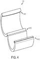
- Figure 4 illustrates the securing device 110 in an open position and removed from the nasal tube 102.
- the securing device 110 is a clip having a hinge 410 (e.g., a living hinge) to allow the body of the clip to pivot between open (unlocked) and closed (locked) positions.
- the clip also comprises a tongue-and-groove style locking mechanism 412 which permits the clip to repeatedly open and close during its use.
- the clip may be constructed of a variety of materials.
- the clip is constructed of a rigid molded polymer material such as polypropylene.
- the shape of the clip when locked generally approximates the external shape of the recessed portion 142 of the nasal tube 102.
- the clip may also have surface textures, depressions, projections, and/or curvatures on its external surface to facilitate its operation.
- the bridle line 208 may be placed between the securing device 110 and the nasal tube 102 to secure the nasal tube device 100 to the patient. As shown, the bridle line 208 extends from the opening 114 in the retention flange 104. Although not shown in Figure 2B , the bridle line 208 may then extend through the first nostril, around the vomer 302 ( Figure 3 ), and out the second nostril of the patient. The second portion 222 of the bridle line 208 extending from the second nostril passes through one or more notches 112 of the tab portions 106 and extends over the external surface of the retention flange 104 to the securing device 110.
- the second portion 222 of the bridle line 208 is then routed between the securing device 110 and the recessed portion 142 of the nasal tube 102 such that the bridle line is secured to the nasal tube when the securing device is closed.
- the first portion 220 of the bridle line 208 is knotted to aid securement of the bridle system 200 to the nasal tube device 100.
- a first portion 220 of the bridle line 208 may also be secured to the nasal tube 102 with the securing device 110 by any of the methods described herein.
- the first portion 220 of the bridle line 208 may be routed between the securing device 110 and the recessed portion 142 of the nasal tube 102 such that the first portion of the bridle line is also secured to the nasal tube when the securing device is closed.
- the bridle line 208 may also be routed through the separated portion 160 of the nasal tube 102 and/or between medical tubes, wires, or medical instruments passing into the lumen 134 of the nasal tube such that the bridle line is secured to the nasal tube when the securing device 110 is closed.
- the bridle line 208 extends from the opening 114 in the retention flange 104, through the first nostril, around the vomer 302, and out the second nostril of the patient.
- the second portion 222 of the bridle line 208 extending from the second nostril then passes through one or more notches 112 of the tab portions 106 and extends over the external surface of the retention flange 104 to the securing device 110.
- the second portion 222 of the bridle line 208 is routed beneath the securing device 110, through the separated portion 160 of the nasal tube 102, and out the lumen 134 such that the bridle line is secured to the nasal tube when the securing device 110 is closed.
- medical tubes also extend out the lumen 134 of the nasal tube 102 and are secured to the nasal tube when the securing device 110 is closed.
- the first portion 220 of the bridle line 208 is also routed beneath the securing device 110, through the separated portion 160 of the nasal tube 102, and out the lumen 134 such that the first portion is secured to the nasal tube when the securing device 110 is closed.
- first portion 220 of the bridle line 208 may be secured to the nasal tube 102 by any of the methods described herein. Further, the first and second portions 220 and 222 extending out of the lumen 134 may also be knotted and/or wrapped around the nasal tube 102 and/or the medical tubes to further secure the bridle line 208 to the nasal tube device 100.
- the nasal tube device 100 may be used for a number of medical purposes.
- the nasal tube device 100 may be used as an oxygen delivery and/or carbon dioxide monitoring aid to support anesthesiology activities.
- an oxygen delivery tube and/or a carbon dioxide sampling tube may pass through the main lumen 134 of the nasal tube device 100 and be secured to the device using the securing device 110.
- the oxygen tube and the carbon dioxide tube may also be adjusted relative to one another to optimize oxygen delivery and carbon dioxide sampling by use of the securing device 110 and its ability to open and lock repeatedly.
- one or more oxygen delivery tubes securely interface with the nasal tube device 100 using the mechanisms described above.
- nasal tube device 100 may be to securely protect a patent airway in a similar fashion to a traditional nasopharyngeal airway device.
- the nasal tube device 100 has a number of advantages over traditional nasopharyngeal airways, notably including the ability to accept a nasal bridle system so as to secure the nasal tube device in position.
- the integrated securing device 110 further allows medical tubes, wires, or instruments to securely interface with the nasal tube device, for all or just part of the device's useful life in the patient.
- the nasal tube device 100 of the present application also couples the benefits of bridle system securement with the temporary use of one or more medical tubes, wires, or medical instruments without directly interfacing or disturbing that bridle securement.
- the retention flange 104 of the nasal tube device may be used in a variety of ways to hold the nasal tube device 100 in position and secured to the patient.
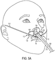
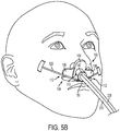
- Figures 5A and 5B illustrate alternative ways of securing the nasal tube device 100 to a patient without passing a bridle line through the nostrils and around the vomer bone 302 of the patient.
- a bridle line 510 extends from one or more openings in the retention flange 104, passes through the notches 112 of the tab portions 106, and extends around the head of the patient to hold the nasal device 100 in place and secured to the patient.
- a bridle line 520 extends from one or more openings in the retention flange 104, passes through the notches 112 of the tab portions 106, and the ends of the bridle line are taped to the head of the patient to hold the nasal device 100 in place and secured to the patient.
- the nasal tube device of the present application may comprise a nasal tube that is configured to deliver at least a portion of the nasal tube retention system into the appropriate pharyngeal space to secure the nasal tube to the patient.
- a connector of the retention system may be delivered via a lumen or passage of the nasal tube.
- the nasal tube device increases the ease of delivery of the retention system for the health care provider.
- the delivery of a connector contained in a nasal tube reduces the procedural delicacy and dexterity required to deliver a traditional nasal retention system.
- delivery of the connector via a lumen or passage of the nasal tube facilitates proper orientation of the connector and prohibits unwanted movement of the connector. For example, when magnets are used, control and proper orientation of the magnet is desirable to establish a magnetic connection between the first and second magnetic connectors. A magnetic connection may fail to occur if the first and second magnets present the same polar magnetic field during placement.
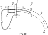
- FIGS 6A-8 illustrate a nasal tube device 600 according to an embodiment of the present application.
- the nasal tube device 600 comprises a nasal tube 602 having a proximal end 630 and a distal end 632, a retention flange 604, and a securing device 610.
- the nasal tube 602 comprises a main lumen 634 extending from the proximal end 630 to the distal end 632 of the nasal tube.
- Figures 6A-6B illustrate the nasal tube device 600 attached to the exemplary retention system 200.
- the retention system 200 comprises the bridle line 208, catheter 202 having the first connector 206 at the distal end, and the connecting member (not shown) having the second connector at the distal end.
- the bridle line 208 is attached to the catheter 202 and the nasal tube device 600.
- the bridle line 208 is threaded through an opening 614 in the retention flange 604 and is knotted to prohibit removal of the line from the nasal tube device 600.
- the first and second connectors may be a variety of devices or fasteners configured to connect or otherwise attach together, e.g., when touched together or when placed in close proximity to one another.
- the first and second connectors are magnets that attach together when placed in proximity to one another.
- the nasal tube device 600 is configured to deliver the connector 206 of the retention system 200 via a lumen or passage of the nasal tube 602.
- the nasal tube 602 comprises a delivery lumen 680 extending from the main lumen 634 and terminating at a delivery window 682 or opening in the outer wall of the nasal tube.
- the entrance opening to the delivery lumen 680 is located in the interior of the proximal portion of the nasal tube approximately at the retention flange 604.
- the delivery window 682 is an opening in the outer wall of the nasal tube 602.
- the connector 206 of the retention system 200 may be delivered through a delivery tube or passage formed on, extending from, or otherwise attached to the outer surface of the nasal tube 602.
- the entrance opening to the delivery lumen 680 is located inside the main lumen 634 of the nasal tube device 600.
- the main lumen 634 and the delivery lumen 680 collectively form a delivery lumen or passage for the connector 206 of the retention system 200 extending from the proximal portion of the nasal tube to the delivery window 682.
- the delivery lumen 680 is completely separate from the main lumen 634, and the entrance opening for the delivery lumen is not located inside the main lumen.
- the entrance opening may be located at the proximal end of the nasal tube, along with the entrance to the main lumen (or other lumens).
- the delivery lumen 680 is configured to permit the bridle line 208 and/or the catheter 202 having the first connector 206 disposed at its distal end to travel through the delivery lumen and out the delivery window 682.
- the nasal tube device 600 delivers the first connector 206 to the appropriate pharyngeal space for connection to the second connector of the connecting member of the retention system 200.
- the first and second connectors are magnets that attach together when placed in proximity to one another.
- the delivery lumen 680 comprises a gentle curve exiting at the delivery window 682 to facilitate delivery of the first connector 206 to the appropriate pharyngeal space for connection to the second connector of the connecting member of the retention system 200.
- the end of the delivery lumen 680 terminating at the delivery window 682 may be tapered to facilitate delivery of the first connector 206 into the appropriate pharyngeal space of the patient.
- the distance of the delivery window 682 from the proximal end 630 of the nasal tube 602 and the orientation of the delivery window on the circumference of the nasal tube will vary depending on the desired delivery location for the first connector 206.
- the nasal tube device 600 is configured such that the delivery window 682 delivers the first connector 206 into the nasophamyx 304 (see Figure 8 ) of the patient when the nasal tube 602 is in position.
- the first connector 206 is positioned for connection to the connecting member of the retention system 200 that is inserted through the nostril of the patient and advanced into the nasopharnyx 304.
- the delivery window 682 is generally between about 5 and 10 cm from the proximal end 630 of the nasal tube 602 along the longitudinal axis of the nasal tube.
- the location of the delivery window 682 will vary depending on the size of the patient and nasal tube 602, and in the cases of animals, the type of patient. For example, this distance may be significantly smaller for pediatric nasal tubes.
- the delivery window 682 is generally orientated medially (i.e., facing the midline of the body) such that the first connector 206 will be positioned in close proximity to the connecting member. Further still, the delivery window 682 may be orientated such that the first connector 206 crosses the midline of the body on an intersecting trajectory with the connecting member.
- the nasal tube device 600 is configured such that the delivery window 682 delivers the first connector 206 into the oropharyngeal space of the patient when the nasal tube 602 is in position.
- the first connector 206 is positioned for connection to the connecting member of the retention system 200 that is inserted through the mouth of the patient and advanced into the oropharyngeal space, The bridle line 208 is pulled through the mouth to establish retention of the nasal tube 602 both nasally and orally.
- the delivery window 682 may be between about 8 and 18 cm from the proximal end 630 of the nasal tube 602 along the longitudinal axis of the nasal tube. This distance will vary depending on the size of the patient and nasal tube 602. Further, depending on the embodiment, the delivery window 682 may be located at a variety of positions between the vomer 302 ( Figure 8 ) and the distal end 632 of the nasal tube 602. For example, in one embodiment, the delivery window 682 is located in the nasopharynx 304 and the catheter 202 is of sufficient length such that the first connector 206 may be delivered to the oropharyngeal space. The connecting member may then be inserted through the mouth of the patient to connect with the first connector 206 of the catheter 202.
- the delivery window 682 is located more towards the distal end 632 of the nasal tube 602 such that the first connector 206 is delivered directly into the oropharyngeal space. Further, the orientation of the delivery window 682 is generally medial or inferior depending on the location of the delivery window along the length of the nasal tube 602.
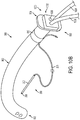
- FIG. 6A-8 An exemplary method of placing and securing a nasal tube to a patient using a nasal tube device having a nasal tube that is configured to deliver a connector of the retention system into the appropriate pharyngeal space is described below with reference to the nasal tube device 600 illustrated in Figures 6A-8 . Further, the method is described with reference to the first connector 206 comprising a magnet such that the magnet is delivered into the appropriate pharyngeal space.
- the method comprises advancing the nasal tube 602 of the nasal tube device 600 into a first nostril of the patient and positioning the nasal tube such that the distal end 632 terminates in a pharyngeal space of the patient, such as for example, the oropharyngeal or largyngopharyngeal space of the patient.
- the nasal tube 602 may or may not be inserted with anesthesia lines, such as oxygen and carbon dioxide lines, already placed inside the lumen 634 of the nasal tube. Anesthesia lines may also be placed into the nasal tube 602 one at a time to free a lumen for other uses.
- the bridle line 208 and/or catheter 202 of the retention system 200 is inserted into the delivery lumen 680 of the nasal tube 602 until the magnet 206 is deployed out the delivery window 682 and into the nasopharnyx 304 (see Figure 8 ).
- An elongated member or pneumatic actuation may be used to facilitate deployment of the magnet 206 out the delivery window 682.
- a magnetic connecting member of the retention system 200 is inserted into the second nostril of the patient and advanced into the nasopharnyx 304 to establish a connection with the magnet 206. It should be noted that it may be clinically advantageous to advance the delivery window 682 slightly beyond the targeted space, then retract the nasal tube 602 and/or twist the nasal tube to establish the magnetic connection with the connecting member. Further, the connecting member may have a slight bend to facilitate finding its magnetic opposite in the nasopharyngeal space by rotating the connecting member in the nose. Once the magnet 206 is connected to the magnetic connecting member, the connecting member is retracted out of the second nostril. Retraction of the connecting member pulls the bridle line 208 through the delivery lumen 680, around the posterior free edge of the vomer bone 302 ( Figure 8 ), and out the second nostril.
- the securing device 610 may be used in a variety of ways to secure the portions of the bridle line 208 extending from the nostrils to the nasal tube 602.
- the vomer 302 anchors the nasal tube 602 against unwanted pullout or retreat and the columella of the nose anchors the nasal tube against unwanted advancement.
- the portions of the bridle line 208 may be tied together or attached in a variety of ways, such as for example, with one or more ties, elastic bands, tape, adhesive, heat shrink tubing, clips or other fasteners or retainers.
- the portions of the bridle line 208 may also be attached or otherwise secured to the nasal tube 602 or components attached to the nasal tube, such as for example, anesthesia lines connected to the nasal tube.
- a flexible linear catheter or probe 202 is used to route the magnet 206 through the magnet delivery lumen 680 and out the magnet delivery window 682 of the nasal tube 602.
- a variety of other methods or devices may be used to deliver the magnet of the retention system into the appropriate pharyngeal space of the patient.
- a curved catheter or probe may be used to route the magnet through the delivery lumen and out the delivery window.
- a separate non-magnetic probe may be used to move the magnet through the delivery lumen and out the delivery window.
- the magnet is attached directly to the flexible bridle line of the retention system and the separate probe is used to move the magnet.
- an additional member such as a probe or elongated member, is not required to deliver the magnet of the retention system through the magnet delivery lumen and out the magnet delivery window of the nasal tube.
- the nasal tube may be configured such that the magnet may be routed through the delivery lumen and out the delivery window without use of another device or member.
- the magnet delivery lumen is configured such that a magnet of the retention system is delivered to the appropriate pharyngeal space of the patient by pulling the line through the delivery lumen. More specifically, the magnet delivery lumen comprises an entrance window and an exit window in the side of the nasal tube. The line is threaded through the magnet delivery lumen, out the exit window, into the entrance window, and back up through the delivery lumen to the proximal end of the nasal tube. Pulling the line through the magnet delivery lumen positions the magnet (which is attached to the flexible line) between the entrance and exit windows such that it is exposed. A magnetic connecting member may then be used to establish a connection with the exposed magnet.
- the nasal tube device of the present application may be configured to be used as a dedicated anesthesiology monitoring/oxygen delivery device.
- the nasal tube device comprises a molded polymer nasal tube having three lumens or passages.
- a magnet delivery lumen extends from a proximal end of the nasal tube to a magnet delivery window on the side of the nasal tube.
- the magnet delivery lumen is used to deliver a magnet of the retention system into the appropriate pharyngeal space of the patient.
- An oxygen delivery lumen extends from the proximal end of the nasal tube to an opening at the distal end of the nasal tube.
- the oxygen delivery lumen is configured to deliver oxygen to the patient.
- a carbon dioxide monitoring lumen extends from the proximal end of the nasal tube to an opening in the side of the nasal tube towards the distal end of the nasal tube.
- the carbon dioxide monitoring lumen facilitates the passage of expired air from the patient to a carbon dioxide monitoring device.
- the nasal tube may be configured such that the oxygen delivery and carbon dioxide monitoring lumens terminate at different levels relative to one another. With the oxygen delivery outlet positioned below the inlet of the carbon dioxide monitoring lumen, the delivered oxygen does not interfere with monitoring of returning carbon dioxide.
- the nasal tube device comprises a molded polymer nasal tube having a magnet delivery lumen.
- an oxygen delivery tube and a carbon dioxide monitoring tube are overmolded with the nasal tube to form the nasal tube device.
- the proximal ends of the oxygen delivery tube and the carbon dioxide monitoring tube comprise connectors for attachment to the corresponding oxygen delivery and carbon dioxide monitoring device(s).
- the oxygen delivery tube forms an oxygen delivery lumen of the nasal tube that extends from the proximal end of the nasal tube to an opening at the distal end of the nasal tube.
- the carbon dioxide monitoring tube forms a carbon dioxide monitoring lumen that extends from the proximal end of the nasal tube to an opening in the side of the nasal tube towards the distal end of the nasal tube.
- the nasal tube is configured such that the oxygen delivery and carbon dioxide monitoring lumens terminate at different levels relative to one another. With the oxygen delivery outlet positioned below the inlet of the carbon dioxide monitoring lumen, the delivered oxygen does not interfere with monitoring of returning carbon dioxide.
- one or more tubes may be at least partially housed in a sheath to form a nasal tube device of the present application.
- a magnet delivery tube, an oxygen delivery tube, and a carbon dioxide monitoring tube are at least partially housed in a sheath to form a nasal tube device.
- the sheath may be configured in a variety of ways, such as, for example, a tubing or wrap that holds the one or more tubes together.
- the sheath comprises heat shrink tubing.
- nasal tube devices are configured to be used as dedicated anesthesiology monitoring/oxygen delivery device, they do not need to have large lumens configured to provide a patent airway for the patient.
- the nasal tube may be smaller in diameter than other nasal tubes, thus reducing the amount of discomfort to the patient.
- the nasal tube devices may be configured to provide a passive patent airway with the addition of an airway lumen or as a function of one or more of the lumens passing air when the nasal tube device is not hooked up to one or more monitoring machines.
- the nasal tube devices may have a variety of cross sectional configurations.
- the nasal tube may comprise three lumens and a delivery lumen for delivery of a connector and flexible line of the retention system.
- the delivery lumen may be circular in shape and completely surround the connector and line of the retention system.
- the line is continuously secured to the nasal tube via the delivery lumen.
- a slit or opening may exist between the delivery lumen and the outer surface of the nasal tube forming a channel for the connector and line of the retention system.
- the line may escape the delivery lumen after placement such that retention of the nasal tube would be located at the clip/tube level.
- the delivery lumen is a circular or non-circular delivery passage formed on or otherwise attached to the outer surface of the nasal tube.
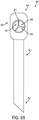
- FIGS 9A-10B illustrate a nasal tube device 900 according to an embodiment of the present application.
- the nasal tube device 900 comprises a nasal tube 902, a retention flange 904, and a securing device 910.
- the nasal tube 902 forms the body of the device 900 and has a proximal end 930 and a distal end 932.
- the nasal tube 902 comprises three lumens extending from the proximal end 930 to the distal end 932 of the tube.
- the nasal tube 902 may comprise more or less lumens, .e.g., one, two, four or more lumens.
- the nasal tube device 900 is shown in Figures 9A , 10A , and 10B attached to an exemplary retention system 200.
- the retention system 200 comprises the bridle line 208, catheter 202 having the first connector 206 (e.g., a magnet) at the distal end, and the connecting member (not shown) having the second connector (e.g., a magnet) at the distal end.
- the bridle line 208 is attached to the catheter 202 and the nasal tube device 900 with the securing device 910.
- the securing device 910 comprises a piece of heat shrink tubing that attaches the bridle line 208 to the nasal tube 902.
- the bridle line 208 may be attached to the nasal tube 902 in a variety of other ways.
- the bridle line 208 may be threaded through an opening in the retention flange 904 and may be knotted to prohibit removal of the line from the nasal tube 902.
- the bridle line 208 may also be attached to the nasal tube 902 by threading the line through a hole in the nasal tube and knotting an end of the line to prohibit removal of the line from the nasal tube.
- the bridle line 208 may be attached to the nasal tube 902 with one or more ties, elastic bands, tape, glue or other adhesive, clips or other fasteners or retainers.
- the bridle line 208 may be attached to the nasal tube 902 with an adhesive, with or without the heat shrink tubing.
- the bridle line 208 may be attached to one or more tubes extending from the lumens of the nasal tube 902, such as, for example, oxygen and carbon dioxide tubes (e.g., with a clip, adhesive and/or heat shrink tubing).
- the bridle line 208 may also be overmolded with the nasal tube 902 to attach the line to the nasal tube device 900.
- the multiple lumens of the nasal tube device 900 may be used for a variety of purposes.
- the nasal tube 902 comprises a first lumen 934, second lumen 936, and third lumen 938.
- the first lumen 934 and the second lumen 936 of the nasal tube 902 segregate gases such as carbon dioxide and oxygen, respectively, that permit the nasal tube device 900 to act as an anesthesia monitoring aid for conscious sedation procedures and a secure passive airway adjunct for perioperative monitoring and continuous airway protection.
- the third lumen 938 is auxiliary and serves as a port for the introduction of instruments such as but not limited to suction catheters or video equipment.
- one or more lumens of the nasal tube may be configured as a delivery lumen for a connector the retention system.
- One exemplary method of placing and securing the nasal tube device 900 to a patient includes inserting the distal end of the catheter 202 into a first nostril of the patient and the distal end of the connecting member into a second nostril of the patient.
- the distal ends of the catheter 202 and the connecting member are advanced into the nasopharnyx 304 ( Figure 3 ).
- the first connector 206 of the catheter 202 meets the second connector of the connecting member in the nasopharnyx 304 to establish a connection.
- the first and second connectors are magnets that attach together when placed in proximity to one another. Once connected, the connecting member is retracted out of the second nostril.
- Retraction of the connecting member pulls the catheter 202 and the bridle line 208 around the posterior free edge of the vomer 302 ( Figure 3 ).
- the nasal tube 902 is advanced into the first nostril of the patient and positioned such that the distal end 932 of the nasal tube terminates in a pharyngeal space of the patient.
- the portions of the bridle line 208 extending from the nostrils may be tied together or attached in a variety of ways, such as for example, with one or more ties, elastic bands, tape, adhesive, heat shrink tubing, clips or other fasteners or retainers.
- the portions of the bridle line 208 may also be attached or otherwise secured to the nasal tube 902 or components attached to the nasal tube, such as for example, anesthesia lines connected to the nasal tube.
- the portions of the bridle line 208 may be attached to one or more tubes extending from the nasal tube 902, such as, for example, oxygen and carbon dioxide tubes, with a clip.
- the portions of the bridle line 208 may be attached together exterior to the nose with a clip.
- the nasal tube device 900 eliminates a step in the overall placement and securement procedure for the nasal tube 902. For example, when a separate nasal tube and nasal tube retention system is used, the bridle line of the retention system is first routed around the vomer of the patient and then the nasal tube is placed over the bridle line. If adequate tension is not maintained on the bridle line during placement of the nasal tube, the line may become dislodged or pulled out of position. The nasal tube device 900 eliminates this step of placing the nasal tube over the bridle line.
- the nasal tube device of the present application may comprise one or more adapters or connectors that facilitate connection of various components or equipment to the nasal tube, such as, for example, one or more anesthesia lines or other respiratory related equipment, such as a bag valve mask.
- the adaptor or connector may be inserted into an end of the nasal tube (e.g., in one or more lumens of the nasal tube) and/or attached to the nasal tube, such as around the circumference of the nasal tube, to a flange of the nasal tube, etc.
- the adapter or connector may be removable, non-removable or integrally formed with the nasal tube and may or may not comprise a flange portion.
- the adapter or connector may be connected to the nasal tube in a variety of ways, such as for example, with an interference fit, slip fit, barbed fitting, locking mechanism, clip, bonded or molded insert, or other fastener.
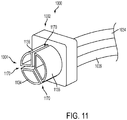
- Figure 11 illustrates an adapter 1000 according to an exemplary embodiment of the present application and Figures 10A and 10B illustrate the adapter 1000 being attached or connected to the nasal tube device 900.
- a first end 1004 of the adapter 1000 comprises a first port 1134, a second port 1136, and a third port 1138 having outer walls that are shaped and configured to be received in the first lumen 934, second lumen 936, and third lumen 938, respectively, of the nasal tube 902.
- the first port 1134 is in fluid communication with the first lumen 934
- the second port 1136 is in fluid communication with the second lumen 936
- the third port 1138 is in fluid communication with the third lumen 938 when the adapter 1000 is inserted into the nasal tube 902.
- the outer walls of the ports 1134, 1136, and 1138 of the adapter 1000 are shaped and configured to provide an interference fit with the lumens 934, 936, and 938 of the nasal tube 902.
- the adapter 1000 may be easily and quickly removed from the nasal tube 902.
- the interference fit provides a fluid tight connection between the ports 1134, 1136, and 1138 of the adapter 1000 and the lumens 934, 936, and 938 of the nasal tube 902.
- the adapter may comprise more or less ports shaped and configured to be received in more or less lumens of the nasal tube.
- the adapter 1000 comprises a slots or spaces 1170 dividing the ports 1134, 1136, and 1138 that facilitate insertion of the adapter into the lumens 934, 936, and 938 of the nasal tube 902.
- the adapter 1000 may be inserted into the nasal tube 902 until the body of the adapter and/or the end wall of the spaces 1170 abuts the walls 970 dividing the lumens 934, 936, and 938.
- a second end 1002 of the adapter 1000 comprises ports in fluid communication with the ports 1134, 1136, and 1138 of the first end 1004.
- the first and second ports of the second end 1002 are configured for removable connection to anesthesia lines 1034 and 1036, respectively.
- a carbon dioxide line 1034 and an oxygen line 1036 are removably connected to the first and second ports, respectively, of the second end 1002 of the adapter 1000.
- the carbon dioxide line 1034 is fluidly connected to the first lumen 934 and the oxygen line 1036 is fluidly connected to the second lumen 936 of the nasal tube 902.
- the adapter 900 may not be limited to the connection of anesthesia related equipment, but may also, for example, accept positive pressure ventilation systems and may comprise one or more valves in such cases.
- the second 1002 of the adapter 1000 comprises a third or auxiliary port 1038 that communicates with the third port 1138 of the first end 1004. Further, the auxiliary port 1038 communicates with the third lumen 938 of the nasal tube 902. In certain embodiments, the auxiliary port 1038 is used to introduce instruments, such as, for example, suction catheters or video equipment, into the third lumen 938 of the nasal tube 902.
- the adapter comprises only the first and second ports for fluidly connecting anesthesia lines 1034 and 1036 to first and second lumens 934 and 936 of the nasal tube 902. Further, in one embodiment, at least a portion of the second end of the two port adapter extends at an angle relative to the first end, e.g., up and away from the first end. As such, the orientation of the second end relative to the first end permits access to the third lumen 938 of the nasal tube 902. As such, the third lumen 938 is not blocked by the adapter, for example the third lumen may still be used to introduce tools such as suction catheters or video equipment.
- the nasal tube device of the present application may comprise connectors for attaching one or more tubes directly to the nasal tube (e.g., at the proximal end of the nasal tube or nare of the nose when the nasal tube is inserted).
- one or more luer connectors may be used to attach the one or more tubes to the nasal tube.
- Male luer connectors may be attached to the lumens of the nasal tube and the mating female luer connectors may be attached to the ends of the one or more tubes.
- the one or more tubes may be attached to the lumens of the nasal tube with a friction fit.
- the one or more tubes may comprise barbed connectors configured to attach to the lumens of the nasal tube.
- one or more lumens of the nasal tube may comprise barbs for attachment of the one or more tubes.
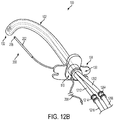
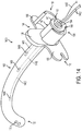
- Figures 12A-13 illustrate the nasal tube device 100 with preloaded medical tubes 1202 and 1212.
- the preloaded medical tubes 1202 and 1212 are placed inside the lumen of the nasal tube 102 and secured prior to placement of the nasal tube on the patient and/or securement of the nasal tube device 100 to the patient.
- the nasal tube device 100 comprises a carbon dioxide monitoring tube 1202 and an oxygen delivery tube 1212 secured within the lumen of the nasal tube 102 with the securing device 110.
- the carbon dioxide monitoring tube 1202 and the oxygen delivery tube 1212 each comprise connectors 1204 and 1214 for removably connecting an external monitoring tube 1206 and an external delivery tube 1216 to the preloaded tubes, as illustrated in Figures 12B and 13 .
- the nasal tube device 100 may comprise a variety of preloaded medical tubes and is not limited to the connection of anesthesia related equipment, but may also, for example, accept positive pressure ventilation systems and may comprise one or more valves in such cases.
- the connectors of the present application may be adapted to attach to other respiratory related equipment, such as, for example, a bag valve mask.
- the oxygen delivery tube 1212 and the carbon dioxide monitoring tube 1202 are positioned in the nasal tube 102 such that they terminate at different body levels relative to one another. Terminating the outlet of the oxygen delivery tube 1212 and the inlet of the carbon dioxide monitoring tube 1202 at different levels reduces the risk that the delivered oxygen will interfere with monitoring of returning carbon dioxide. As shown, the outlet of the oxygen delivery tube 1212 is positioned below the inlet of the carbon dioxide monitoring tube 1202.
- the nasal tube device 100 is configured to be used as an oxygen delivery and/or carbon dioxide monitoring aid to support anesthesiology activities.
- the oxygen delivery tube 1212 and/or the carbon dioxide sampling tube 1202 may be preloaded into the main lumen of the nasal tube device 100 and secured to the device using the securing device 110.
- the oxygen tube 1212 and the carbon dioxide tube 1202 may also be adjusted relative to one another to optimize oxygen delivery and carbon dioxide sampling by use of the securing device 110 and its ability to open and lock repeatedly.
- one or more oxygen delivery tubes and/or one or more carbon dioxide monitoring tubes may securely interface with the nasal tube device 100 using the mechanisms described above.
- one or more medical tubes, wires, and/or medical instruments may be preloaded inside the lumen of the nasal tube 102 and secured prior to placement of the nasal tube 102 on the patient and/or securement of the nasal tube device 100 to the patient.
- the securing device 110 also permits the preloaded medical tubes, wires, and/or medical instruments to be quickly removed such that the nasal tube device 100 may be used to securely protect a patent airway in a similar fashion to a traditional nasopharyngeal airway device.
- a wide variety of connectors may be used to connect the one or more external tubes to one or more tubes extending from the nasal tube 102. Further, in certain embodiments, the connectors may be adapted to attach to other respiratory related equipment, such as, for example, a bag valve mask. As illustrated in Figures 12A-13 , the connectors 1204 and 1214 are luer connectors configured to attach the external tubes 1206 and 1216 to the tubes 1202 and 1212 extending from the nasal tube 102. In certain embodiments, molded connectors may be attached to the ends of the tubes extending from the nasal tube (e.g., with a friction fit or adhesive). The molded connectors may comprise ports for attachment to the one or more external tubes. Further, barbed connectors may be used to attach the one or more external tubes to the one or more tubes extending from the nasal tube.
- the nasal tubes of the present application are sufficiently strong and flexible to permit advancement and placement of the tube in the patient and prohibit undesirable collapse or compression of the tube under pressure imparted by the patient's anatomical structures. Further, the nasal tubes of the present application are sufficiently flexible such that the tube may be bent or otherwise manipulated during advancement and placement, such as for example, when the tube dives from the nasopharyngeal into the oropharyngeal space. Further, the exterior of the nasal tube may be soft to protect the delicate and vasoactive nasal mucosa and epithelium.
- the nasal tubes of the present application may comprise a variety of materials.
- many moldable polymers may be used for the nasal tube, such as silicone, polyvinyl chloride (PVC), block co-polymers, other thermoplastic elastomers, and natural rubber. These polymers generally possess the physical properties and biocompatible characteristics needed for the nasal tubes for the present application.
- the polymer material of the nasal tube may have a high melt temperature and/or electrical insulating characteristics.
- the nasal tube comprises silicone to aid in the prevention of nasal airway fires during electrosurgical procedures of the head and neck. Silicone has no melting point. Silicone's tolerance to high heat may add additional patient and caregiver protection in the event of an operating room fire.
- silicone will not melt which adds protection from tube melt blockages and associated tissue damage as the tube's material responds to the intense thermal exposure during operating room fires.
- the nasal tube devices of the present application segregate and sequester gases, especially oxygen, and controls them until they are out of reach of surface electrosurgical arcing and ignition surfaces.
- the nasal tubes of the present application may be various lengths and diameters to accommodate different sized patient anatomies.
- the cross section of the nasal tube may be a variety of sizes and shapes and may or may not be uniform along the length of the nasal tube.
- the cross section of the nasal tube may be circular, ovoid, elliptical, oval, or other non-circular shapes.
- Various non-circular shapes may provide stability for ease of insertion and compliance with regard to the nasal anatomy and long-term retention.
- the nasal tubes of the present application may be curved along the longitudinal axis to mimic the anatomy of the patient and aid in directing the distal end of the tube during insertion at the posterior nasophamyx.
- the proximal end of the nasal tube may also have a slight flare to accommodate adapters and function as an anchor point for the retention system.
- the nasal tube or nasal retention system components may also comprise indicators or graduations along its length to facilitate proper alignment and estimation of the nasal tube position within the nose, such as for example, the position of the delivery window.
- the exterior of the nasal tube and/or the retention system components may also comprise drug treatments such as but not limited to anti-bacterial, vasoactive, analgesic agents or combinations of drugs.
- the exterior may also include surface treatments for hydrophilicity, hydrophobicity, and/or lubricious treatments to aid in insertion of device.
- the lubricious and/or drug treatments may be packaged with a breakable liquid pouch to immediately activate the surface treatments.
- the external surface of the nasal tube may be textured along its longitudinal axis or morphologically incongruent to aid in tube insertion and rotational stability as the tube navigates through the nasal passage and levels of the nasal choanae.
- the nasal tubes of the present application may also comprise holes or other perforations along the length of the tube to permit the directed exchange of gases.
- the tube exterior may comprise closed cell foam or anticoagulant packing.
- the exterior of the nasal tube may also comprise coatings or surface treatments that expand, swell, bulge, or otherwise increase the outer size of the nasal tube in the presence of moisture.
- the expanded portion of the nasal tube may act as an anchor and increase the friction between the nasal tube and the patient to facilitate retention of the tube in the patient. Further, the expanded portion of the tube may act as packing for hemostatis purposes, such as to decrease or prohibit nasal bleeding.
- the nasal tube device of the present application may comprise one or more sensors disposed in a lumen of the nasal tube or on the surface of the nasal tube.
- the sensors may be used to monitor various physiological conditions of the patient.
- a pulse oximeter or other monitoring sensor may be disposed in one or more lumens of the nasal tube or on the surface of the nasal tube.
- wires attached to the sensor may be routed through the lumen of the nasal tube and back out of the nasal tube device.
- the monitoring sensors may also be incorporated onto the exterior of the nasal tube device or disposed within one or more lumens of the nasal tube device.
- Various types of monitoring sensors may include electrodes for heart rate, temperature sensors, pulse oximeters, EKG, etc.
- Figure 14 illustrates a nasal tube device 1400 according to an embodiment of the present application.
- the nasal tube device 1400 comprises a plurality of the sensors 1400 disposed on the surface of the nasal tube 102.
- the sensors 1400 may be attached to the surface or integrated into the nasal tube 102 in a variety of ways, such as, for example, with a friction fit (e.g., disposed in an opening or slit in the nasal tube), one or more fasteners, adhesive, tape, elastic band, weld, overmold, etc.
- Wires 1402 attached to the sensors 1400 are routed through the lumen 134 of the nasal tube 102 and out of the nasal tube device 1400 for connection to one or more pieces of monitoring equipment.
- the wires 1402 may be secured to the nasal tube 102 when the securing device 110 is closed.
- the sensors 1400 may be various types of patient monitoring sensors, including but not limited to heart rate sensors, temperature sensors, pulse oximeters, EKG, carbon dioxide or oxygen sensors, etc. As shown, the sensors 1400 are disposed at various locations on the nasal tube 102 and at various distances from the proximal end 130 of the nasal tube. As such, one or more of the sensors 1400 may be positioned to monitor the patient at various body levels.
- one or more of the sensors 1400 may be disposed in the lumen 134 or incorporated onto the exterior of the nasal tube device and the wires may or may not be routed through the lumen. Further, the sensors 1400 may be wireless and capable communicating remotely with one or more pieces of monitoring equipment.
- interconnection may be direct as between the components or may be in direct such as through the use of one or more intermediary components.
- reference to a "member,” “component,” or “portion” shall not be limited to a single structural member, component, or element but can include an assembly of components, members or elements.
Claims (7)
- Dispositif de tube nasal (100) comprenant : un tube nasal (102) ayant une partie proximale (130), une partie distale (132), une bride de retenue (104) et une ou plusieurs lumières (134) ; un dispositif de fixation (110) fixé à la partie proximale (130) du tube nasal (102) et un système de retenue (200) ayant une conduite flexible (208), dans lequel la bride de retenue (104) comprend une ou plusieurs ouvertures (114) pour fixer la conduite flexible du système de retenue (200) au tube nasal (102), dans lequel le dispositif de tube nasal (100) est configuré de sorte que, lorsque le dispositif de tube nasal (100) est fixé à un patient, la conduite flexible (208) s'étend à partir des une ou plusieurs ouvertures (114) de la bride de retenue (104) autour de l'os du vomer du patient, et est fixée à la partie proximale (130) du tube nasal (102) par le dispositif de fixation (110).
- Dispositif de tube nasal (100) selon la revendication 1, dans lequel le dispositif de fixation (110) est configuré pour comprimer la partie proximale (130) du tube nasal (102), et dans lequel le dispositif de fixation (110) est une attache qui entoure sensiblement la partie proximale (130) du tube nasal (102) dans une position fermée.
- Dispositif de tube nasal (100) selon la revendication 1, dans lequel le dispositif de fixation (110) est configuré pour comprimer la partie proximale (130) du tube nasal (102) pour fixer un ou plusieurs tubes médicaux (1202, 1212) disposés dans la lumière (134) du tube nasal (102).
- Dispositif de tube nasal (100) selon la revendication 1, dans lequel la partie distale (132) du tube nasal (102) comprend une ou plusieurs ouvertures (170).
- Dispositif de tube nasal (100) selon la revendication 1, dans lequel le dispositif de fixation (110) est une bande élastique configurée pour comprimer la partie proximale (130) du tube nasal (102).
- Dispositif de tube nasal (100) selon la revendication 1, dans lequel la conduite flexible est nouée pour empêcher le retrait de la conduite du dispositif de tube nasal (100).
- Dispositif de tube nasal (100) selon la revendication 1, comprenant en outre un ou plusieurs capteurs (1400) disposés sur le tube nasal (102).
Applications Claiming Priority (4)
| Application Number | Priority Date | Filing Date | Title |
|---|---|---|---|
| US201261661148P | 2012-06-18 | 2012-06-18 | |
| US201261740848P | 2012-12-21 | 2012-12-21 | |
| US13/839,012 US10426941B2 (en) | 2012-06-18 | 2013-03-15 | Nasal tube device and method |
| PCT/US2013/046213 WO2013192121A1 (fr) | 2012-06-18 | 2013-06-18 | Dispositif de tube nasal et procédé |
Publications (3)
| Publication Number | Publication Date |
|---|---|
| EP2861289A1 EP2861289A1 (fr) | 2015-04-22 |
| EP2861289A4 EP2861289A4 (fr) | 2016-06-15 |
| EP2861289B1 true EP2861289B1 (fr) | 2018-03-07 |
Family
ID=49756531
Family Applications (1)
| Application Number | Title | Priority Date | Filing Date |
|---|---|---|---|
| EP13807038.8A Active EP2861289B1 (fr) | 2012-06-18 | 2013-06-18 | Dispositif de tube nasal |
Country Status (3)
| Country | Link |
|---|---|
| US (1) | US10426941B2 (fr) |
| EP (1) | EP2861289B1 (fr) |
| WO (1) | WO2013192121A1 (fr) |
Families Citing this family (23)
| Publication number | Priority date | Publication date | Assignee | Title |
|---|---|---|---|---|
| US20140364838A1 (en) * | 2012-06-26 | 2014-12-11 | iMed Technology, Inc. | Nasal retention system including a foam clip |
| CN104225752B (zh) * | 2013-06-14 | 2019-07-05 | 北京谊安医疗系统股份有限公司 | 气体传输管和具有该气体传输管的医疗设备 |
| CA158527S (en) * | 2014-03-07 | 2015-05-18 | Seven Dreamers Lab Inc | Nasal airway tube |
| GB201405244D0 (en) * | 2014-03-24 | 2014-05-07 | T & T Devices Ltd | A nasal bridle insertion device |
| US20170095630A1 (en) * | 2014-05-30 | 2017-04-06 | Wake Forest University Health Sciences | Oxygen Port Nasal Cannula |
| US20160067435A1 (en) * | 2014-07-23 | 2016-03-10 | Diana B. Thomas | Endopharyngeal airway device and kit and method of use |
| US11413416B2 (en) * | 2014-07-23 | 2022-08-16 | Diana B. Thomas | Endopharyngeal airway positive pressure ventilation device |
| US10973504B2 (en) * | 2014-08-05 | 2021-04-13 | Paulino Edwardo Goco | Retractor suction catheter |
| WO2016128881A1 (fr) * | 2015-02-13 | 2016-08-18 | Fondazione Poliambulanza | Dispositif de respiration assistée |
| US9808182B2 (en) * | 2015-03-20 | 2017-11-07 | Bohnas LLC | Breathing detection apparatus |
| ITUB20159256A1 (it) * | 2015-12-23 | 2017-06-23 | Deas S R L | Cannula nasofaringea |
| US20210077761A1 (en) * | 2017-09-17 | 2021-03-18 | Glenn Fernandes | Lung cleansing apparatus and method |
| USD936825S1 (en) * | 2018-03-09 | 2021-11-23 | Hu-Friedy Mfg Co., Llc | Capnography fitting |
| TWI661846B (zh) * | 2018-05-10 | 2019-06-11 | 許瑞哲 | 隱藏式鼻胃管 |
| GB201812444D0 (en) * | 2018-07-28 | 2018-09-12 | Smith Medical International Ltd | Tracheal tubes |
| GB201812443D0 (en) * | 2018-07-28 | 2018-09-12 | Smith Medical International Ltd | Tracheal tubes |
| US11000661B2 (en) * | 2018-09-24 | 2021-05-11 | NPA Medical, LLC | Nasopharyngeal airway device |
| USD878548S1 (en) * | 2018-11-16 | 2020-03-17 | Brandi Lane | Side indent nasal airway |
| USD893705S1 (en) * | 2019-02-12 | 2020-08-18 | H&H Medical Corporation | Nasopharyngeal airway |
| TWI698236B (zh) * | 2019-03-15 | 2020-07-11 | 施長碧 | 鼻胃管結構 |
| NL2023355B1 (en) | 2019-06-21 | 2021-02-01 | Stichting Katholieke Univ | Oropharyngeal airway device |
| CN110477971A (zh) * | 2019-09-03 | 2019-11-22 | 上海市胸科医院 | 鞘管结构、反式支气管镜及其使用方法 |
| US20230031503A1 (en) * | 2021-07-28 | 2023-02-02 | Avent, Inc. | Bridle Delivery System Having Reduced-Contact Bridle |
Family Cites Families (45)
| Publication number | Priority date | Publication date | Assignee | Title |
|---|---|---|---|---|
| FR1336296A (fr) | 1962-07-19 | 1963-08-30 | Dispositif pour maintenir en place un tube nasal | |
| US3420237A (en) * | 1966-09-02 | 1969-01-07 | Martha K Fortay | Process and article for the treatment of severe epistaxis |
| FR1555589A (fr) | 1967-07-25 | 1969-01-31 | ||
| US3776222A (en) * | 1971-12-23 | 1973-12-04 | Lurosso A | Fiber optic entubator and method of entubation of the trachea through the nasopharynx |
| US4778448A (en) * | 1985-09-10 | 1988-10-18 | Meer Jeffrey A | Naso-enteral tube harness apparatus and method |
| US4821715A (en) * | 1988-02-16 | 1989-04-18 | Downing Michael V | Nasopharyngeal airway |
| US4932943A (en) * | 1988-05-23 | 1990-06-12 | Hollister Incorporated | Nasogastric tube holding device |
| US5097827A (en) | 1991-03-22 | 1992-03-24 | Ddi Industries, Inc. | Holder for medical tubing |
| US5185005A (en) | 1991-06-04 | 1993-02-09 | Board Of Regents, The University Of Texas System | Method and apparatus for securing a nasogastric tube |
| US6408850B1 (en) * | 1993-02-09 | 2002-06-25 | Michael Sudge | Medical tube holder apparatus |
| US5492538A (en) * | 1994-08-25 | 1996-02-20 | Johlin, Jr.; Frederick C. | Method for transferring the exit site of a catheter from the mouth to the nose and instrumentation useful therefor |
| US5692506A (en) * | 1996-08-01 | 1997-12-02 | Linder; Gerald S. | Transnasal conduit and method of use |
| US5782236A (en) * | 1996-08-09 | 1998-07-21 | Ess; Steven M. | Ventilator tube retaining device for endotracheal tube or tracheostomy |
| US5752511A (en) | 1996-11-22 | 1998-05-19 | Simmons; Carl J. | Universal medical tube retainer and nasal wall tissue dilator |
| DK9700387U3 (da) | 1997-10-16 | 1998-02-13 | Boerge Kaersgaard | Magnetfixtur med bevægelige krystaller til behandling af patienter |
| US5937858A (en) | 1997-12-05 | 1999-08-17 | Connell; Donald G. | Oro/nasopharyngeal airway for administering/sampling inhalent/expired gases |
| US6098617A (en) * | 1997-12-05 | 2000-08-08 | Connell; Donald G. | Device for administering/sampling inhalant/expired gases in an oro/nasopharyngeal airway |
| US6173199B1 (en) | 1998-05-05 | 2001-01-09 | Syncro Medical Innovations, Inc. | Method and apparatus for intubation of a patient |
| CA2343207A1 (fr) * | 1998-09-09 | 2000-03-16 | U.S. Army Institute Of Surgical Research | Canule nasopharyngee avec capteur de sphygmo-oxymetre a reflectance |
| US6394093B1 (en) * | 1999-05-13 | 2002-05-28 | Scott Lethi | Nasopharyngeal airway with inflatable cuff |
| US6159158A (en) | 1999-07-06 | 2000-12-12 | Lowe; Michael W. | Diagnostic catheter system for nasopharyngeal obstructions |
| US6464668B1 (en) | 1999-09-21 | 2002-10-15 | Patrick Pace | Nasogastric tube stabilizer |
| US6488664B1 (en) | 2000-07-28 | 2002-12-03 | Koninklijke Phillips Electronics | Easily releasable clamp |
| JP2004508108A (ja) | 2000-09-01 | 2004-03-18 | キアン メディカル デザイン,エル.エル.シー. | 磁気経鼻管ブライドル装置およびその応用方法 |
| US6837237B2 (en) | 2001-08-24 | 2005-01-04 | Kirn Medical Design, L.L.C. | Magnetic nasal tube bridle system and related method |
| US6789538B2 (en) * | 2002-11-27 | 2004-09-14 | Medical Device Group, Inc. | Rescue device and kit and method of using same |
| US20040231675A1 (en) | 2003-05-20 | 2004-11-25 | Lyons James R. | Method and apparatus for transnasal ventilation |
| US7654997B2 (en) * | 2004-04-21 | 2010-02-02 | Acclarent, Inc. | Devices, systems and methods for diagnosing and treating sinusitus and other disorders of the ears, nose and/or throat |
| US7534228B2 (en) | 2004-04-27 | 2009-05-19 | Applied Medical Technology, Inc. | Bridle catheter with umbilical tape |
| US7730888B2 (en) * | 2004-09-09 | 2010-06-08 | Spivan, Llc | Nasopharyngeal airway device and method of use |
| US8105316B2 (en) * | 2005-03-25 | 2012-01-31 | Nalini Vadivelu | Medical apparatus with hypropharyngeal suctioning capability |
| US8522782B2 (en) | 2005-09-12 | 2013-09-03 | Mergenet Medical, Inc. | High flow therapy device utilizing a non-sealing respiratory interface and related methods |
| US7604627B2 (en) * | 2006-05-11 | 2009-10-20 | Kourosh Kojouri | Nasopharyngeal sheath for nasogastric intubation |
| US20080006275A1 (en) | 2006-07-07 | 2008-01-10 | Steven Nickelson | Composite masks and methods for positive airway pressure therapies |
| US8056562B2 (en) | 2006-09-28 | 2011-11-15 | Nellcor Puritan Bennett Llc | System and method for providing support for a breathing passage |
| US8020558B2 (en) * | 2007-01-26 | 2011-09-20 | Cs Medical, Inc. | System for providing flow-targeted ventilation synchronized to a patient's breathing cycle |
| WO2008144589A1 (fr) * | 2007-05-18 | 2008-11-27 | Breathe Technologies, Inc. | Procédés et dispositifs pour détecter la respiration et fournir une thérapie de ventilation |
| JP5513392B2 (ja) * | 2007-09-26 | 2014-06-04 | ブリーズ・テクノロジーズ・インコーポレーテッド | 睡眠時無呼吸を治療するための方法及び装置 |
| US8092478B2 (en) * | 2008-04-01 | 2012-01-10 | Robert Kotler | Device and method for maintaining unobstructed nasal passageways after nasal surgery |
| WO2010107894A1 (fr) * | 2009-03-17 | 2010-09-23 | Nasolex | Traitement des apnées du sommeil avec déviation naso-pharyngée |
| WO2011159997A1 (fr) * | 2010-06-17 | 2011-12-22 | Kirn Medical Design Llc | Dispositif permettant de fixer un tube buccal chez un patient |
| US20120080037A1 (en) * | 2010-10-05 | 2012-04-05 | Innovative Medical Equipment, Llc | Nasopharyngeal airway |
| WO2012064732A1 (fr) * | 2010-11-08 | 2012-05-18 | Dale Medical Products, Inc. | Support de tube endotrachéal |
| US20130019872A1 (en) * | 2011-07-20 | 2013-01-24 | Bahman Guyuron | Nasopharyngeal airway |
| US20130152940A1 (en) * | 2011-12-20 | 2013-06-20 | Ian Walker Larson | Nasopharyngeal Trumpet with Inflatable Tip |
-
2013
- 2013-03-15 US US13/839,012 patent/US10426941B2/en active Active
- 2013-06-18 EP EP13807038.8A patent/EP2861289B1/fr active Active
- 2013-06-18 WO PCT/US2013/046213 patent/WO2013192121A1/fr active Application Filing
Non-Patent Citations (1)
| Title |
|---|
| None * |
Also Published As
| Publication number | Publication date |
|---|---|
| US10426941B2 (en) | 2019-10-01 |
| US20130338521A1 (en) | 2013-12-19 |
| EP2861289A4 (fr) | 2016-06-15 |
| WO2013192121A1 (fr) | 2013-12-27 |
| EP2861289A1 (fr) | 2015-04-22 |
Similar Documents
| Publication | Publication Date | Title |
|---|---|---|
| EP2861289B1 (fr) | Dispositif de tube nasal | |
| US11179531B2 (en) | Apparatus, systems, and methods for accessing the airway with medical instruments without interruption of assisted respiration | |
| US9925348B2 (en) | Gas delivery device | |
| US7171962B1 (en) | Soft oral airway for intravenous anesthesia and method of use | |
| EP2112937B1 (fr) | Interface nasale | |
| US6561193B1 (en) | Nasal gas delivery apparatus and a nasal vestibular airway | |
| EP1659939B1 (fr) | Appareil buccal d'oxygenation ameliore | |
| CN101227946B (zh) | 保持外科手术气道的装置及其方法 | |
| JP6616828B2 (ja) | 多目的エアウェイデバイスのための封止機構 | |
| US20130125895A1 (en) | Nasal interface device | |
| US20120080037A1 (en) | Nasopharyngeal airway | |
| US20130019872A1 (en) | Nasopharyngeal airway | |
| AU2023100076A4 (en) | Breath Sampling Interface | |
| TWI802069B (zh) | 氣體取樣介面及氣體取樣頭 | |
| CN217138912U (zh) | 用于婴幼儿的气管导管固定装置 | |
| US20220241537A1 (en) | Respiration Aid | |
| WO2016115158A1 (fr) | Dispositif de voies aériennes ayant de multiples canaux | |
| KR20230110872A (ko) | 비출혈 감소형 비인두 삽입기 | |
| WO2018031278A1 (fr) | Dispositif d'administration de gaz. |
Legal Events
| Date | Code | Title | Description |
|---|---|---|---|
| PUAI | Public reference made under article 153(3) epc to a published international application that has entered the european phase |
Free format text: ORIGINAL CODE: 0009012 |
|
| 17P | Request for examination filed |
Effective date: 20150116 |
|
| AK | Designated contracting states |
Kind code of ref document: A1 Designated state(s): AL AT BE BG CH CY CZ DE DK EE ES FI FR GB GR HR HU IE IS IT LI LT LU LV MC MK MT NL NO PL PT RO RS SE SI SK SM TR |
|
| AX | Request for extension of the european patent |
Extension state: BA ME |
|
| DAX | Request for extension of the european patent (deleted) | ||
| RA4 | Supplementary search report drawn up and despatched (corrected) |
Effective date: 20160518 |
|
| RIC1 | Information provided on ipc code assigned before grant |
Ipc: A61B 5/083 20060101ALI20160511BHEP Ipc: A61B 5/08 20060101ALI20160511BHEP Ipc: A61B 5/00 20060101ALI20160511BHEP Ipc: A61M 16/04 20060101ALI20160511BHEP Ipc: A61B 5/0205 20060101ALI20160511BHEP Ipc: A61M 16/08 20060101ALI20160511BHEP Ipc: A61M 16/10 20060101ALI20160511BHEP Ipc: A61M 25/02 20060101AFI20160511BHEP |
|
| GRAJ | Information related to disapproval of communication of intention to grant by the applicant or resumption of examination proceedings by the epo deleted |
Free format text: ORIGINAL CODE: EPIDOSDIGR1 |
|
| STAA | Information on the status of an ep patent application or granted ep patent |
Free format text: STATUS: GRANT OF PATENT IS INTENDED |
|
| GRAP | Despatch of communication of intention to grant a patent |
Free format text: ORIGINAL CODE: EPIDOSNIGR1 |
|
| INTG | Intention to grant announced |
Effective date: 20170915 |
|
| RAP1 | Party data changed (applicant data changed or rights of an application transferred) |
Owner name: APPLIED MEDICAL TECHNOLOGY, INC. |
|
| GRAS | Grant fee paid |
Free format text: ORIGINAL CODE: EPIDOSNIGR3 |
|
| GRAA | (expected) grant |
Free format text: ORIGINAL CODE: 0009210 |
|
| STAA | Information on the status of an ep patent application or granted ep patent |
Free format text: STATUS: THE PATENT HAS BEEN GRANTED |
|
| AK | Designated contracting states |
Kind code of ref document: B1 Designated state(s): AL AT BE BG CH CY CZ DE DK EE ES FI FR GB GR HR HU IE IS IT LI LT LU LV MC MK MT NL NO PL PT RO RS SE SI SK SM TR |
|
| REG | Reference to a national code |
Ref country code: GB Ref legal event code: FG4D |
|
| REG | Reference to a national code |
Ref country code: CH Ref legal event code: EP Ref country code: AT Ref legal event code: REF Ref document number: 975899 Country of ref document: AT Kind code of ref document: T Effective date: 20180315 |
|
| REG | Reference to a national code |
Ref country code: IE Ref legal event code: FG4D |
|
| REG | Reference to a national code |
Ref country code: DE Ref legal event code: R096 Ref document number: 602013034152 Country of ref document: DE |
|
| REG | Reference to a national code |
Ref country code: FR Ref legal event code: PLFP Year of fee payment: 6 |
|
| REG | Reference to a national code |
Ref country code: NL Ref legal event code: FP |
|
| REG | Reference to a national code |
Ref country code: LT Ref legal event code: MG4D |
|
| PG25 | Lapsed in a contracting state [announced via postgrant information from national office to epo] |
Ref country code: ES Free format text: LAPSE BECAUSE OF FAILURE TO SUBMIT A TRANSLATION OF THE DESCRIPTION OR TO PAY THE FEE WITHIN THE PRESCRIBED TIME-LIMIT Effective date: 20180307 Ref country code: CY Free format text: LAPSE BECAUSE OF FAILURE TO SUBMIT A TRANSLATION OF THE DESCRIPTION OR TO PAY THE FEE WITHIN THE PRESCRIBED TIME-LIMIT Effective date: 20180307 Ref country code: FI Free format text: LAPSE BECAUSE OF FAILURE TO SUBMIT A TRANSLATION OF THE DESCRIPTION OR TO PAY THE FEE WITHIN THE PRESCRIBED TIME-LIMIT Effective date: 20180307 Ref country code: LT Free format text: LAPSE BECAUSE OF FAILURE TO SUBMIT A TRANSLATION OF THE DESCRIPTION OR TO PAY THE FEE WITHIN THE PRESCRIBED TIME-LIMIT Effective date: 20180307 Ref country code: HR Free format text: LAPSE BECAUSE OF FAILURE TO SUBMIT A TRANSLATION OF THE DESCRIPTION OR TO PAY THE FEE WITHIN THE PRESCRIBED TIME-LIMIT Effective date: 20180307 Ref country code: NO Free format text: LAPSE BECAUSE OF FAILURE TO SUBMIT A TRANSLATION OF THE DESCRIPTION OR TO PAY THE FEE WITHIN THE PRESCRIBED TIME-LIMIT Effective date: 20180607 |
|
| REG | Reference to a national code |
Ref country code: AT Ref legal event code: MK05 Ref document number: 975899 Country of ref document: AT Kind code of ref document: T Effective date: 20180307 |
|
| PG25 | Lapsed in a contracting state [announced via postgrant information from national office to epo] |
Ref country code: RS Free format text: LAPSE BECAUSE OF FAILURE TO SUBMIT A TRANSLATION OF THE DESCRIPTION OR TO PAY THE FEE WITHIN THE PRESCRIBED TIME-LIMIT Effective date: 20180307 Ref country code: BG Free format text: LAPSE BECAUSE OF FAILURE TO SUBMIT A TRANSLATION OF THE DESCRIPTION OR TO PAY THE FEE WITHIN THE PRESCRIBED TIME-LIMIT Effective date: 20180607 Ref country code: GR Free format text: LAPSE BECAUSE OF FAILURE TO SUBMIT A TRANSLATION OF THE DESCRIPTION OR TO PAY THE FEE WITHIN THE PRESCRIBED TIME-LIMIT Effective date: 20180608 Ref country code: SE Free format text: LAPSE BECAUSE OF FAILURE TO SUBMIT A TRANSLATION OF THE DESCRIPTION OR TO PAY THE FEE WITHIN THE PRESCRIBED TIME-LIMIT Effective date: 20180307 Ref country code: LV Free format text: LAPSE BECAUSE OF FAILURE TO SUBMIT A TRANSLATION OF THE DESCRIPTION OR TO PAY THE FEE WITHIN THE PRESCRIBED TIME-LIMIT Effective date: 20180307 |
|
| PG25 | Lapsed in a contracting state [announced via postgrant information from national office to epo] |
Ref country code: RO Free format text: LAPSE BECAUSE OF FAILURE TO SUBMIT A TRANSLATION OF THE DESCRIPTION OR TO PAY THE FEE WITHIN THE PRESCRIBED TIME-LIMIT Effective date: 20180307 Ref country code: PL Free format text: LAPSE BECAUSE OF FAILURE TO SUBMIT A TRANSLATION OF THE DESCRIPTION OR TO PAY THE FEE WITHIN THE PRESCRIBED TIME-LIMIT Effective date: 20180307 Ref country code: AL Free format text: LAPSE BECAUSE OF FAILURE TO SUBMIT A TRANSLATION OF THE DESCRIPTION OR TO PAY THE FEE WITHIN THE PRESCRIBED TIME-LIMIT Effective date: 20180307 Ref country code: EE Free format text: LAPSE BECAUSE OF FAILURE TO SUBMIT A TRANSLATION OF THE DESCRIPTION OR TO PAY THE FEE WITHIN THE PRESCRIBED TIME-LIMIT Effective date: 20180307 Ref country code: IT Free format text: LAPSE BECAUSE OF FAILURE TO SUBMIT A TRANSLATION OF THE DESCRIPTION OR TO PAY THE FEE WITHIN THE PRESCRIBED TIME-LIMIT Effective date: 20180307 |
|
| PG25 | Lapsed in a contracting state [announced via postgrant information from national office to epo] |
Ref country code: AT Free format text: LAPSE BECAUSE OF FAILURE TO SUBMIT A TRANSLATION OF THE DESCRIPTION OR TO PAY THE FEE WITHIN THE PRESCRIBED TIME-LIMIT Effective date: 20180307 Ref country code: SM Free format text: LAPSE BECAUSE OF FAILURE TO SUBMIT A TRANSLATION OF THE DESCRIPTION OR TO PAY THE FEE WITHIN THE PRESCRIBED TIME-LIMIT Effective date: 20180307 Ref country code: SK Free format text: LAPSE BECAUSE OF FAILURE TO SUBMIT A TRANSLATION OF THE DESCRIPTION OR TO PAY THE FEE WITHIN THE PRESCRIBED TIME-LIMIT Effective date: 20180307 Ref country code: CZ Free format text: LAPSE BECAUSE OF FAILURE TO SUBMIT A TRANSLATION OF THE DESCRIPTION OR TO PAY THE FEE WITHIN THE PRESCRIBED TIME-LIMIT Effective date: 20180307 |
|
| REG | Reference to a national code |
Ref country code: DE Ref legal event code: R097 Ref document number: 602013034152 Country of ref document: DE |
|
| PG25 | Lapsed in a contracting state [announced via postgrant information from national office to epo] |
Ref country code: PT Free format text: LAPSE BECAUSE OF FAILURE TO SUBMIT A TRANSLATION OF THE DESCRIPTION OR TO PAY THE FEE WITHIN THE PRESCRIBED TIME-LIMIT Effective date: 20180709 |
|
| PLBE | No opposition filed within time limit |
Free format text: ORIGINAL CODE: 0009261 |
|
| STAA | Information on the status of an ep patent application or granted ep patent |
Free format text: STATUS: NO OPPOSITION FILED WITHIN TIME LIMIT |
|
| PG25 | Lapsed in a contracting state [announced via postgrant information from national office to epo] |
Ref country code: DK Free format text: LAPSE BECAUSE OF FAILURE TO SUBMIT A TRANSLATION OF THE DESCRIPTION OR TO PAY THE FEE WITHIN THE PRESCRIBED TIME-LIMIT Effective date: 20180307 |
|
| REG | Reference to a national code |
Ref country code: CH Ref legal event code: PL |
|
| 26N | No opposition filed |
Effective date: 20181210 |
|
| PG25 | Lapsed in a contracting state [announced via postgrant information from national office to epo] |
Ref country code: SI Free format text: LAPSE BECAUSE OF FAILURE TO SUBMIT A TRANSLATION OF THE DESCRIPTION OR TO PAY THE FEE WITHIN THE PRESCRIBED TIME-LIMIT Effective date: 20180307 |
|
| REG | Reference to a national code |
Ref country code: BE Ref legal event code: MM Effective date: 20180630 |
|
| REG | Reference to a national code |
Ref country code: IE Ref legal event code: MM4A |
|
| PG25 | Lapsed in a contracting state [announced via postgrant information from national office to epo] |
Ref country code: LU Free format text: LAPSE BECAUSE OF NON-PAYMENT OF DUE FEES Effective date: 20180618 Ref country code: MC Free format text: LAPSE BECAUSE OF FAILURE TO SUBMIT A TRANSLATION OF THE DESCRIPTION OR TO PAY THE FEE WITHIN THE PRESCRIBED TIME-LIMIT Effective date: 20180307 |
|
| PG25 | Lapsed in a contracting state [announced via postgrant information from national office to epo] |
Ref country code: IE Free format text: LAPSE BECAUSE OF NON-PAYMENT OF DUE FEES Effective date: 20180618 Ref country code: CH Free format text: LAPSE BECAUSE OF NON-PAYMENT OF DUE FEES Effective date: 20180630 Ref country code: LI Free format text: LAPSE BECAUSE OF NON-PAYMENT OF DUE FEES Effective date: 20180630 |
|
| PG25 | Lapsed in a contracting state [announced via postgrant information from national office to epo] |
Ref country code: BE Free format text: LAPSE BECAUSE OF NON-PAYMENT OF DUE FEES Effective date: 20180630 |
|
| PG25 | Lapsed in a contracting state [announced via postgrant information from national office to epo] |
Ref country code: MT Free format text: LAPSE BECAUSE OF NON-PAYMENT OF DUE FEES Effective date: 20180618 |
|
| PG25 | Lapsed in a contracting state [announced via postgrant information from national office to epo] |
Ref country code: TR Free format text: LAPSE BECAUSE OF FAILURE TO SUBMIT A TRANSLATION OF THE DESCRIPTION OR TO PAY THE FEE WITHIN THE PRESCRIBED TIME-LIMIT Effective date: 20180307 |
|
| PG25 | Lapsed in a contracting state [announced via postgrant information from national office to epo] |
Ref country code: HU Free format text: LAPSE BECAUSE OF FAILURE TO SUBMIT A TRANSLATION OF THE DESCRIPTION OR TO PAY THE FEE WITHIN THE PRESCRIBED TIME-LIMIT; INVALID AB INITIO Effective date: 20130618 Ref country code: MK Free format text: LAPSE BECAUSE OF NON-PAYMENT OF DUE FEES Effective date: 20180307 |
|
| PG25 | Lapsed in a contracting state [announced via postgrant information from national office to epo] |
Ref country code: IS Free format text: LAPSE BECAUSE OF FAILURE TO SUBMIT A TRANSLATION OF THE DESCRIPTION OR TO PAY THE FEE WITHIN THE PRESCRIBED TIME-LIMIT Effective date: 20180707 |
|
| PGFP | Annual fee paid to national office [announced via postgrant information from national office to epo] |
Ref country code: NL Payment date: 20230609 Year of fee payment: 11 Ref country code: FR Payment date: 20230622 Year of fee payment: 11 Ref country code: DE Payment date: 20230629 Year of fee payment: 11 |
|
| PGFP | Annual fee paid to national office [announced via postgrant information from national office to epo] |
Ref country code: GB Payment date: 20230606 Year of fee payment: 11 |