EP2861136B1 - System and method for magnetic resonance imaging using a rotating array of permanent magnets - Google Patents
System and method for magnetic resonance imaging using a rotating array of permanent magnets Download PDFInfo
- Publication number
- EP2861136B1 EP2861136B1 EP12878991.4A EP12878991A EP2861136B1 EP 2861136 B1 EP2861136 B1 EP 2861136B1 EP 12878991 A EP12878991 A EP 12878991A EP 2861136 B1 EP2861136 B1 EP 2861136B1
- Authority
- EP
- European Patent Office
- Prior art keywords
- permanent magnets
- magnet assembly
- magnetic field
- magnetic resonance
- longitudinal axis
- Prior art date
- Legal status (The legal status is an assumption and is not a legal conclusion. Google has not performed a legal analysis and makes no representation as to the accuracy of the status listed.)
- Active
Links
- 238000002595 magnetic resonance imaging Methods 0.000 title claims description 63
- 238000000034 method Methods 0.000 title claims description 15
- 230000005284 excitation Effects 0.000 claims description 9
- 238000003384 imaging method Methods 0.000 claims description 9
- 208000032843 Hemorrhage Diseases 0.000 description 5
- 230000005415 magnetization Effects 0.000 description 4
- 230000003068 static effect Effects 0.000 description 4
- 210000004556 brain Anatomy 0.000 description 3
- 238000013461 design Methods 0.000 description 3
- 238000001514 detection method Methods 0.000 description 3
- 239000000696 magnetic material Substances 0.000 description 3
- 239000011159 matrix material Substances 0.000 description 3
- 238000005259 measurement Methods 0.000 description 3
- 229910001172 neodymium magnet Inorganic materials 0.000 description 3
- 208000016988 Hemorrhagic Stroke Diseases 0.000 description 2
- 208000006011 Stroke Diseases 0.000 description 2
- 102000003978 Tissue Plasminogen Activator Human genes 0.000 description 2
- 108090000373 Tissue Plasminogen Activator Proteins 0.000 description 2
- 208000030886 Traumatic Brain injury Diseases 0.000 description 2
- 238000013459 approach Methods 0.000 description 2
- 230000008901 benefit Effects 0.000 description 2
- 239000002131 composite material Substances 0.000 description 2
- 230000001419 dependent effect Effects 0.000 description 2
- 239000011152 fibreglass Substances 0.000 description 2
- 230000002008 hemorrhagic effect Effects 0.000 description 2
- 208000020658 intracerebral hemorrhage Diseases 0.000 description 2
- 230000004807 localization Effects 0.000 description 2
- 239000000463 material Substances 0.000 description 2
- 229910052761 rare earth metal Inorganic materials 0.000 description 2
- 238000004088 simulation Methods 0.000 description 2
- 238000001356 surgical procedure Methods 0.000 description 2
- 229960000187 tissue plasminogen activator Drugs 0.000 description 2
- 230000009529 traumatic brain injury Effects 0.000 description 2
- 241001269524 Dura Species 0.000 description 1
- 206010018852 Haematoma Diseases 0.000 description 1
- 206010019196 Head injury Diseases 0.000 description 1
- 238000005481 NMR spectroscopy Methods 0.000 description 1
- 208000002667 Subdural Hematoma Diseases 0.000 description 1
- 206010042364 Subdural haemorrhage Diseases 0.000 description 1
- 208000027418 Wounds and injury Diseases 0.000 description 1
- QJVKUMXDEUEQLH-UHFFFAOYSA-N [B].[Fe].[Nd] Chemical compound [B].[Fe].[Nd] QJVKUMXDEUEQLH-UHFFFAOYSA-N 0.000 description 1
- 229920000122 acrylonitrile butadiene styrene Polymers 0.000 description 1
- 210000000576 arachnoid Anatomy 0.000 description 1
- 239000008280 blood Substances 0.000 description 1
- 210000004369 blood Anatomy 0.000 description 1
- 208000029028 brain injury Diseases 0.000 description 1
- 230000006835 compression Effects 0.000 description 1
- 238000007906 compression Methods 0.000 description 1
- 238000010276 construction Methods 0.000 description 1
- 238000012937 correction Methods 0.000 description 1
- 230000006378 damage Effects 0.000 description 1
- 238000011161 development Methods 0.000 description 1
- 238000010586 diagram Methods 0.000 description 1
- 229940079593 drug Drugs 0.000 description 1
- 239000003814 drug Substances 0.000 description 1
- 238000002592 echocardiography Methods 0.000 description 1
- 239000003527 fibrinolytic agent Substances 0.000 description 1
- 125000004435 hydrogen atom Chemical group [H]* 0.000 description 1
- 208000014674 injury Diseases 0.000 description 1
- 239000007769 metal material Substances 0.000 description 1
- 238000012986 modification Methods 0.000 description 1
- 230000004048 modification Effects 0.000 description 1
- 238000001208 nuclear magnetic resonance pulse sequence Methods 0.000 description 1
- 230000010363 phase shift Effects 0.000 description 1
- 239000004033 plastic Substances 0.000 description 1
- 229920003023 plastic Polymers 0.000 description 1
- 230000010287 polarization Effects 0.000 description 1
- 238000012545 processing Methods 0.000 description 1
- 150000002910 rare earth metals Chemical class 0.000 description 1
- 238000005070 sampling Methods 0.000 description 1
- 230000035945 sensitivity Effects 0.000 description 1
- 229960000103 thrombolytic agent Drugs 0.000 description 1
Images


Classifications
-
- G—PHYSICS
- G01—MEASURING; TESTING
- G01R—MEASURING ELECTRIC VARIABLES; MEASURING MAGNETIC VARIABLES
- G01R33/00—Arrangements or instruments for measuring magnetic variables
- G01R33/20—Arrangements or instruments for measuring magnetic variables involving magnetic resonance
- G01R33/28—Details of apparatus provided for in groups G01R33/44 - G01R33/64
- G01R33/32—Excitation or detection systems, e.g. using radio frequency signals
- G01R33/34—Constructional details, e.g. resonators, specially adapted to MR
- G01R33/34092—RF coils specially adapted for NMR spectrometers
-
- A—HUMAN NECESSITIES
- A61—MEDICAL OR VETERINARY SCIENCE; HYGIENE
- A61B—DIAGNOSIS; SURGERY; IDENTIFICATION
- A61B5/00—Measuring for diagnostic purposes; Identification of persons
- A61B5/05—Detecting, measuring or recording for diagnosis by means of electric currents or magnetic fields; Measuring using microwaves or radio waves
- A61B5/055—Detecting, measuring or recording for diagnosis by means of electric currents or magnetic fields; Measuring using microwaves or radio waves involving electronic [EMR] or nuclear [NMR] magnetic resonance, e.g. magnetic resonance imaging
-
- A—HUMAN NECESSITIES
- A61—MEDICAL OR VETERINARY SCIENCE; HYGIENE
- A61B—DIAGNOSIS; SURGERY; IDENTIFICATION
- A61B5/00—Measuring for diagnostic purposes; Identification of persons
- A61B5/0033—Features or image-related aspects of imaging apparatus classified in A61B5/00, e.g. for MRI, optical tomography or impedance tomography apparatus; arrangements of imaging apparatus in a room
- A61B5/004—Features or image-related aspects of imaging apparatus classified in A61B5/00, e.g. for MRI, optical tomography or impedance tomography apparatus; arrangements of imaging apparatus in a room adapted for image acquisition of a particular organ or body part
- A61B5/0042—Features or image-related aspects of imaging apparatus classified in A61B5/00, e.g. for MRI, optical tomography or impedance tomography apparatus; arrangements of imaging apparatus in a room adapted for image acquisition of a particular organ or body part for the brain
-
- G—PHYSICS
- G01—MEASURING; TESTING
- G01R—MEASURING ELECTRIC VARIABLES; MEASURING MAGNETIC VARIABLES
- G01R33/00—Arrangements or instruments for measuring magnetic variables
- G01R33/20—Arrangements or instruments for measuring magnetic variables involving magnetic resonance
- G01R33/28—Details of apparatus provided for in groups G01R33/44 - G01R33/64
- G01R33/38—Systems for generation, homogenisation or stabilisation of the main or gradient magnetic field
- G01R33/383—Systems for generation, homogenisation or stabilisation of the main or gradient magnetic field using permanent magnets
-
- G—PHYSICS
- G01—MEASURING; TESTING
- G01R—MEASURING ELECTRIC VARIABLES; MEASURING MAGNETIC VARIABLES
- G01R33/00—Arrangements or instruments for measuring magnetic variables
- G01R33/20—Arrangements or instruments for measuring magnetic variables involving magnetic resonance
- G01R33/44—Arrangements or instruments for measuring magnetic variables involving magnetic resonance using nuclear magnetic resonance [NMR]
- G01R33/46—NMR spectroscopy
-
- G—PHYSICS
- G01—MEASURING; TESTING
- G01R—MEASURING ELECTRIC VARIABLES; MEASURING MAGNETIC VARIABLES
- G01R33/00—Arrangements or instruments for measuring magnetic variables
- G01R33/20—Arrangements or instruments for measuring magnetic variables involving magnetic resonance
- G01R33/28—Details of apparatus provided for in groups G01R33/44 - G01R33/64
- G01R33/38—Systems for generation, homogenisation or stabilisation of the main or gradient magnetic field
- G01R33/3802—Manufacture or installation of magnet assemblies; Additional hardware for transportation or installation of the magnet assembly or for providing mechanical support to components of the magnet assembly
-
- G—PHYSICS
- G01—MEASURING; TESTING
- G01R—MEASURING ELECTRIC VARIABLES; MEASURING MAGNETIC VARIABLES
- G01R33/00—Arrangements or instruments for measuring magnetic variables
- G01R33/20—Arrangements or instruments for measuring magnetic variables involving magnetic resonance
- G01R33/44—Arrangements or instruments for measuring magnetic variables involving magnetic resonance using nuclear magnetic resonance [NMR]
- G01R33/445—MR involving a non-standard magnetic field B0, e.g. of low magnitude as in the earth's magnetic field or in nanoTesla spectroscopy, comprising a polarizing magnetic field for pre-polarisation, B0 with a temporal variation of its magnitude or direction such as field cycling of B0 or rotation of the direction of B0, or spatially inhomogeneous B0 like in fringe-field MR or in stray-field imaging
-
- G—PHYSICS
- G01—MEASURING; TESTING
- G01R—MEASURING ELECTRIC VARIABLES; MEASURING MAGNETIC VARIABLES
- G01R33/00—Arrangements or instruments for measuring magnetic variables
- G01R33/20—Arrangements or instruments for measuring magnetic variables involving magnetic resonance
- G01R33/44—Arrangements or instruments for measuring magnetic variables involving magnetic resonance using nuclear magnetic resonance [NMR]
- G01R33/48—NMR imaging systems
- G01R33/4818—MR characterised by data acquisition along a specific k-space trajectory or by the temporal order of k-space coverage, e.g. centric or segmented coverage of k-space
- G01R33/4824—MR characterised by data acquisition along a specific k-space trajectory or by the temporal order of k-space coverage, e.g. centric or segmented coverage of k-space using a non-Cartesian trajectory
Definitions
- the field of the invention is systems and methods for magnetic resonance imaging ("MRI"). More particularly, the invention relates to systems and methods for portable MRI using an inhomogeneous magnetic field for spatial encoding.
- MRI magnetic resonance imaging
- a conventional MRI scanner uses several different magnetic fields to produce an image.
- One field is a static, highly uniform magnetic field that is used to polarize the nuclear magnetization and in which a free-induction decay (“FID") signal is read-out.
- Another field is a radio frequency (“RF") pulsed field to initiate the FID.
- RF radio frequency
- one or more gradient fields are used to encode the spatial location from which the FID originates, thereby spatially encoding the resulting image.
- the gradient fields are spatially changing (e.g., linear with position) gradient fields that modulate the spin phase as a function of position. As a result of the modulate spin phase, the location of the signal is encoded as the Fourier transform of the acquired signal.
- a nonhomogeneous pre-polarization field is used to boost the initial magnetization, which is then read-out in a uniform, lower strength field.
- a portable MR system has the potential to quickly detect brain injury at the site of injury.
- hemorrhage detection is critical for both stroke patients and traumatic brain injury victims.
- rapid distinction between a hemorrhagic and non-hemorrhagic event could allow administration of a clot-busting drug such as tPA (tissue plasminogen activator) in an ambulance prior to transportation to the hospital, perhaps advancing this time-sensitive treatment by up to an hour.
- tPA tissue plasminogen activator
- Subdural hemorrhage or hematoma is a form of traumatic brain injury, in which blood gathers between the dura and arachnoid mater (in meningeal layer) and is likely to be visualized on course resolution (e.g. 5mm) T1 images.
- the present invention overcomes the aforementioned drawbacks by providing a portable magnetic resonance imaging (“MRI”) system that uses its naturally inhomogeneous magnetic field to spatially encode magnetic resonance signals.
- MRI magnetic resonance imaging
- a portable MRI system includes a magnet assembly, a rotator, a radio frequency (“RF") coil, and a controller.
- the magnet assembly includes a plurality of permanent magnets and a support. Each of the plurality of permanent magnets extend from a proximal end to a distal end along a longitudinal axis of the magnet assembly.
- the support is configured to hold the plurality of permanent magnets in an annular arrangement so as to define a region configured to receive an object to be imaged.
- the support is also configured to hold the plurality of permanent magnets such that the permanent magnets generate a magnetic field that varies with spatial location in a plane transverse to the longitudinal axis of the magnet assembly.
- the rotator is coupled to the magnet assembly and configured to rotate the magnet assembly about its longitudinal axis through a plurality of different rotation angles.
- the RF coil is configured to generate RF energy and receive magnetic resonance signals from an object positioned in the magnet assembly.
- the controller is configured to direct the rotator to rotate the magnet assembly through the plurality of different rotation angles and to direct the RF coil to generate RF energy and receive responsive magnetic resonance signals at each rotation angle.
- Claim 11 defines a corresponding method for acquiring magnetic resonance imaging data using an annular array of permanent magnets. Further detailed embodiments are described in the dependent claims. In the description, reference is made to the accompanying drawings which form a part hereof, and in which there is shown by way of illustration a preferred embodiment of the invention. Such embodiment does not necessarily represent the full scope of the invention, however, and reference is made therefore to the claims and herein for interpreting the scope of the invention.
- a portable magnetic resonance imaging (“MRI”) system that uses static magnetic field inhomogeneities in the main magnet for encoding the spatial location of nuclear spins is provided. Also provided is a spatial-encoding scheme for a low-field, low-power consumption, light-weight, and easily transportable MRI system.
- the portable MRI system of the present invention employs spatial inhomogeneities in the polarizing B 0 magnetic field rather than gradient fields to spatially encode images.
- an inhomogeneous static field is used to polarize, readout, and encode an image of the object.
- the magnet is rotated around the object to generate a number of differently encoded measurements. An image is then reconstructed by solving for the object most consistent with the data, for example in the least-squares sense, with or without the use of constrains or prior knowledge (other than the spatial map of the B 0 field).
- the portable MRI system of the present invention may be used to detect hemorrhage in emergency situations, to monitor for hemorrhage in the intensive care unit ("ICU") after brain surgery at a patient's bedside, or to detect hemorrhagic stroke at an early stage.
- ICU intensive care unit
- the latter application is particularly useful as the early detection of hemorrhagic stroke can accelerate the application of an anti-thrombolytic agent, thereby improving the patient's clinical outcome.
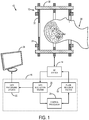
- the portable MRI system 10 of the present invention generally includes a magnet assembly 12, a radio frequency (“RF") system 14, and a controller 16.
- the controller 16 may include, for example, a pulse sequence system 18, a data acquisition system 20, a data processing system 22, and a control processor 24.
- the portable MRI system 10 may also include a display 26 for viewing images of the subject 28 obtained with the portable MRI system 10 and for providing a user interface between the operator and the controller 16.
- the portable MRI system 10 does not require gradient coils or high-power gradient amplifiers.
- the RF system 14 and controller 16 may be constructed of small signal electronics an a small RF power amplifier, all of which can easily fit in the back of an ambulance.
- the magnet assembly 12 generally includes a plurality of permanent magnets 30 arranged in an annular Halbach array.
- the permanent magnets 30 are held in spaced arrangement by a support 32 to form the annular Halbach array.
- the support 32 may be constructed of plastic, fiberglass, or another suitable, preferably non-magnetic, material.
- the magnet assembly 12 may also include end-ring permanent magnets 34 arranged at the end of permanent magnets 30 for reducing the fall-off of the magnetic field at the ends of the magnet assembly 12.
- the magnet assembly 12 may be configured to weigh no more than eighty kilograms, making it relatively light-weight and portable. Unlike clinical MRI systems, the magnet assembly 12 of the present invention is composed of permanent magnets; thus, it requires no cryogens. In other configurations of the magnet assembly 12 where a light-weight superconducting magnet may be used, cryogens may be required. However, because the homogeneity requirement of the magnetic field can be relaxed, the weight of such a superconducting magnet is significantly reduced compared to those superconducting magnets used in conventional clinical MRI systems.
- FIGS. 2-5 An example of a magnet assembly 12 that may form a part of the portable MRI system 10 of the present invention is illustrated in FIGS. 2-5 .
- the magnet assembly 12 includes a plurality of permanent magnets 30 that are arranged in a Halbach array.
- a Halbach array arrangement is preferred because it creates a relatively uniform magnetic field without the need for a cryostat or power supplies.
- the magnet assembly 12 may include a light-weight superconducting magnet. The weight of such a magnet can be so reduced because the magnetic field of the superconducting magnet does not need to be as homogeneous as in conventional clinical MRI systems. Because of this relaxed homogeneity requirement, the weight of a superconducting magnet may be reduced significantly enough to be used in the magnet assembly 12 of the portable MRI system 10.
- the magnet assembly 12 is designed to maximize the average magnetic field strength while allowing for small, controlled variations in the magnetic field for spatial encoding. Simulations such as COMSOL simulations may be used to optimize the magnetic field of the magnet assembly based on varying one or more parameters. Examples of parameters that can be varied in the magnet design include the size and quantity of the magnets 30; the size of the magnet assembly 12; and the addition of smaller rings for end field correction, such as end-ring magnets 34.
- the permanent magnets 30 are composed of a magnetic material, such as a magnetic metallic material, a composite magnetic material, or a rare-earth magnetic material.
- the permanent magnets 30 may be composed of a rare-earth element materials, such as neodymium-iron-boron ("NdFeB").
- the permanent magnets 30 are preferably shaped as rods that extend from a proximal end to a distal end along the longitudinal axis of the magnet assembly.
- each permanent magnet 30 will preferably have a polygonal cross-section.
- the cross-section of the permanent magnets 30 may be a square, rectangle, circle, hexagon, or the like.
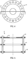
- the magnet assembly 12 illustrated in FIGS. 2-5 includes rod-shaped permanent magnets 30 with a square cross-section.
- each permanent magnet 30 is rotated about its longitudinal axis relative to other adjacent permanent magnets 30.
- the magnet assembly 12 may include twenty permanent magnets 30, with each permanent magnet rotated relative to adjacent permanent magnets 30.
- this configuration results in a spatially rotating pattern of magnetization, which, in turn, results in the generation of a magnetic field in the center 36 of the magnet assembly 12 and the cancellation of the magnetic field near to zero on the exterior of the magnet assembly 12.
- each of the twenty permanent magnets 30 is a radially magnetized NdFeB N42 magnet that is fourteen inches long and one inch-by-one inch square.
- the permanent magnets 30 may be placed into sleeves, such as fiberglass sleeves, to constrain them.
- the permanent magnets 30 may be forced into such sleeves using a compression jig and can be epoxied into place.
- Each of the sleeves may be oriented at the proper angle and held in place by the support 32.
- the support 32 may be composed of water-jet cut ABS plastic.
- the support 32 may include two end rings and a middle ring.
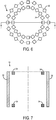
- an additional loop of one cubic inch end-ring magnets 34 may be arranged at each end of the permanent magnets 30, as illustrated in FIGS. 6 and 7 .
- the end-ring magnets 34 reduce the fall-off of the magnet field at the ends of the magnet assembly 12, thereby improving the uniformity of the magnetic field along the longitudinal axis of the magnet assembly 12.
- FIGS. 8 and 9 an example of the in-plane magnetic field profile of the magnet assembly 12 of the portable MRI system 10 shown in FIG. 2 is illustrated.
- This magnetic field is transverse to the longitudinal axis of the magnet assembly 12; thus, when the portable MRI system 10 is used to image a patient's head, the magnet assembly 12 will produce a magnetic field with spatial variations suitable for spatial encoding in a plane perpendicular to the superior-inferior direction, or in oblique planes that are angled with respect to the transverse plane.
- FIG. 8 illustrates the field profile at three different longitudinal positions along the magnet assembly 12. These positions include the center of the magnet assembly 12, and four centimeters above and below the center of the magnet assembly 12.
- FIG. 9 illustrates the magnetic field profiles for the same magnet assembly 12 at the same longitudinal positions; however, the magnet field represented in FIG. 9 has been shimmed by the addition of additional magnets to the magnet assembly 12, such as by end-ring magnets 34.
- the natural inhomogeneities of a magnet assembly 12 constructed in this manner are largely quadratic and well suited for spatially encoding magnetic resonance signals when rotated about the object being imaged into different measurement orientations.
- the magnetic field profile of the magnet assembly 12 produces a central Larmor frequency for hydrogen protons of 3.3 MHz, which is suitable for imaging. While the homogeneity of the magnetic field generated by the magnet assembly 12 is well below that of superconducting magnets, the field shape allows for the inhomogeneities to be used for image encoding.
- the inhomogeneous magnetic field of the magnet assembly 12 serves to polarize the object to be imaged and to readout magnetic resonance signals.
- the spatial position the readout magnetic resonance signals is then encoded by taking multiple measurements with the magnet assembly 12 rotated to different orientations around the object. For example, the first acquisition might have the B 0 field oriented transversely from left-to-right through the object. Then, the acquisition would be repeated with the magnet assembly 12 rotated in ten degree increments until thirty six different acquisitions, each with a unique magnetic field orientation, are obtained.
- the spatial inhomogeneities in the magnetic field generated by the magnet assembly 12 spatially modulate the magnetic resonance signal phase, thereby providing spatial encoding of the signals that can be used to reconstruct an image of the object.
- image reconstruction detailed prior knowledge about the field profile for every orientation is used. For instance, image reconstruction is typically performed using an iterative algorithm to solve for the unknown image given complete knowledge of the encoding matrix.
- the rotation of the magnet assembly 12 is accomplished by way of a rotator that is coupled to the support 32 of the magnet assembly 12.
- the rotator may include a gantry coupled to the support 32 or a set of rollers on which the magnet assembly 12 rests and is allowed to roll about its longitudinal axis.
- the spatial localization of magnetic resonance signals can be improved by using an array of RF receive coils. Information from the RF receive coil array may then be used to detect the signals in a process analogous to parallel imaging in conventional MRI. During reconstruction, the spatially varying coil sensitivities are incorporated directly into the encoding matrix. Further image encoding can also be achieved by limiting the bandwidth of the RF excitation pulse used. In this case, the excitation is limited to a constrained "onion-shell" of spatial regions. Still further improved spatial localization can be achieved by using the so-called "TRASE” method, in which a z-dependent spatial phase is applied using the RF transmit coil or coils.
- TRASE so-called "TRASE” method
- the challenge with portable MRI systems is how to perform spatial encoding without the use of switched gradient coils.
- the present invention provides a system that does not require gradient coils.
- the lack of gradient coils offers numerous benefits, including lower power consumption, reduced complexity, the ability to use low-homogeneity and, therefore, light-weight permanent or superconducting magnets, and silent operation during imaging.
- a further discussion of spatial encoding with the portable MRI system 10 of the present invention is now provided.
- Transverse encoding is achieved as follows.
- the Halbach array configuration of the magnet assembly 12 naturally forms a nonlinear magnetic field whose variation in Larmor frequency (which varies about 50-100 KHz over the FOV) can be used for spatial encoding.
- the approximate shape of the magnetic field generated by the magnet assembly 12 illustrated in FIG. 2 is a second-order quadrupolar spherical harmonic, similar to a Patloc encoding field, which is described by J. Hennig, et al., in "Parallel imaging in non-bijective, curvilinear magnetic field gradients: a concept study," MAGMA, 2008; 21(1-2): 5-14 .
- the magnet assembly 12 is rotated, either in discrete steps or continuously, and projections are acquired at each rotation angle.
- the readout direction is preferably selected to allow ⁇ radians of relative phase to evolve between neighboring voxels near the periphery of the magnet assembly 12. Allowing too much phase to evolve will result in intravoxel dephasing.
- the readout duration is related to the reconstruction resolution achievable with the portable MRI system 10.
- the sampling rate during readout should be set to be at least double the highest absolute spatial frequency occurring in the imaging field-of-view.
- linear terms can be generated in the magnetic field inhomogeneities. These linear terms can be generated, for example, by providing to the magnet assembly 12 a second array of permanent magnets in the next higher Halbach mode, which would form a linear field that could be rotated independently of the main magnet assembly 12.
- a traditional linear gradient term is applied with a second array of permanent magnets, conventional radial MR encoding can be used.
- the k-space trajectory is a radial trajectory starting at isocenter.
- Application of a 180 pulse reverses the trajectory allowing it to pass thru the origin of k-space.
- Data acquisition then includes recording one linear projection per rotated position of the linear gradient magnet array.
- the magnetic field can be offset from the isocenter of the head, so the "encoding hole” moves in a circular arc thru the head as the magnet is rotated. Rotating an offset field shape will remove the "encoding hole” in the center of the FOV.
- TRASE transmit array spatial encoding
- MRI magnetic field phase gradients
- Magn Reson Med, 2010;63(1):151-161 and by Q. Deng, et al., in "1D RF Phase Gradient Coil for TRASE RF Imaging," Proc. ISMRM, 2011; 1813 .
- a linear phase imparted to the magnetization by an RF coil during excitation provides phase encoding along longitudinal direction.
- the linear phase is produced, for example, using a spiral birdcage coil or Maxwell/Helmholtz pairs to achieve the requisite 180 degree phase shift over the desired field-of-view.
- This linear phase variation along the longitudinal direction imparts a k-space shift during RF excitation which does not depend on RF pulse shape.
- This requires a conventional constant-phase coil, or an array of coils, to be used for signal reception. If the same coil is used for transmit and receive, no net phase encoding is performed.
- 180 degree pulses can be applied with one coil and a second coil can be used to observe the spin refocusing in between 180 degree pulses, as in a normal echo train.
- the TRASE method has synergy with the aforementioned transverse encoding in general because trains of multiple echoes will be required at each array rotation angle to obtain sufficient SNR. These same 180 degree pulses could be used for slice selection via TRASE encoding.
- An alternative longitudinal encoding strategy is to use RF pulses with quadratic phase to isolate signals coming from the "vertex" of a parabola of RF-induced phase modulation, as described by J.G. Pipe in "Spatial encoding and reconstruction in MRI with quadratic phase profiles," Magn. Reson. Med., 1995; 33(1):24-33 , and by R. Chamberlain, et al., in "RASER: a new ultrafast magnetic resonance imaging method," Magn. Reson. Med., 2007; 58(4):794-799 .
- the vertex of the parabola can be translated in a given direction. Away from the vertex, spins are dephased and contribute minimally to the acquired signal.
- Another alternative method for longitudinal encoding is to use the natural variations of the magnetic field of the magnet assembly 12 along its longitudinal axis.
- the object being imaged can be excited with a hard pulse and frequency isocontours can be disambiguated in three dimensions, with additional spatial encoding provided by the surface coils in the receive array.
- RF excitation in the portable MRI system 10 of the present invention is complicated by the fact that most spins are significantly off-resonance at all times, including while the RF transmit pulse is being played.
- the duration of the RF pulse should be set so as to achieve a sufficiently wide-band excitation. If the duration of the RF pulse must be longer due to limited available RF power, composite pulses can be designed to produce the same excitation phase for all frequencies across the object.
- An alternative approach is to use a suboptimal RF pulse and then incorporate the resulting spatially-varying phase into the encoding matrix during reconstruction.
- a portable MRI system has been provided.
- the magnet assembly of the portable MRI system achieves reasonable homogeneity, but also provides inhomogeneities that are used to enable spatial encoding of magnetic resonance signals without the need for a gradient coil system.
- the portable MRI system can be constructed to weigh on the order of 45-80 kilograms and requires no power to maintain a magnetic field.
- the cost of building such a portable MRI system was only a few thousand dollars, making it a far less expensive alternative to traditional MRI systems.
- the accessibility of this portable MRI system has the potential to offer basic head trauma and hemorrhaging detection to a broad range of applications.
Description
- The field of the invention is systems and methods for magnetic resonance imaging ("MRI"). More particularly, the invention relates to systems and methods for portable MRI using an inhomogeneous magnetic field for spatial encoding.
- A conventional MRI scanner uses several different magnetic fields to produce an image. One field is a static, highly uniform magnetic field that is used to polarize the nuclear magnetization and in which a free-induction decay ("FID") signal is read-out. Another field is a radio frequency ("RF") pulsed field to initiate the FID. Also, one or more gradient fields are used to encode the spatial location from which the FID originates, thereby spatially encoding the resulting image. The gradient fields are spatially changing (e.g., linear with position) gradient fields that modulate the spin phase as a function of position. As a result of the modulate spin phase, the location of the signal is encoded as the Fourier transform of the acquired signal. Sometimes a nonhomogeneous pre-polarization field is used to boost the initial magnetization, which is then read-out in a uniform, lower strength field.
- Much of the size and complexity of an MRI system derives from the fact that typical clinical MRI systems require a very homogeneous static magnetic field and very high-power linear gradient fields. Thus, current MRI systems are limited to hospital settings due to the weight and fragility of highly homogeneous superconducting or permanent magnets. An additional burden is the need for hundreds of amps of current to power the gradient fields. To make the MRI system portable, a new type of MR encoding scheme is needed. It has not been sufficient to simply "shrink down" current designs.
- A portable MR system has the potential to quickly detect brain injury at the site of injury. For example hemorrhage detection is critical for both stroke patients and traumatic brain injury victims. In stroke, rapid distinction between a hemorrhagic and non-hemorrhagic event could allow administration of a clot-busting drug such as tPA (tissue plasminogen activator) in an ambulance prior to transportation to the hospital, perhaps advancing this time-sensitive treatment by up to an hour. Subdural hemorrhage (or hematoma) is a form of traumatic brain injury, in which blood gathers between the dura and arachnoid mater (in meningeal layer) and is likely to be visualized on course resolution (e.g. 5mm) T1 images. Rapid diagnostics of the hemorrhage in the field could substantially accelerate treatment by adverting a "wait and see" approach. After brain surgery, some patients develop a hemorrhage that must be treated immediately. A bedside MRI in a neuro-ICU would allow frequent checks for the development of such hemorrhaging.
- Others have disclosed portable nuclear magnetic resonance spectrometers; however, even these systems still make use of conventional encoding schemes that require gradients.
- An example of a portable MR system using a Halbach array of permanent magnets is described in Zimmerman et al. in "Design and Construction of a Halbach Array Magnet for Portable Brain MRI", Proc. Intl. Soc. Mag. Reson. Med., 20th Annual Meeting & Exhibition, 2012.
- It would therefore be desirable to provide a portable MRI system that does not require the use of magnetic field gradient coils to provide spatial encoding of magnetic resonance signals.
- The present invention overcomes the aforementioned drawbacks by providing a portable magnetic resonance imaging ("MRI") system that uses its naturally inhomogeneous magnetic field to spatially encode magnetic resonance signals.
- It is an aspect of the invention to provide a portable MRI system according to claim 1 that includes a magnet assembly, a rotator, a radio frequency ("RF") coil, and a controller. The magnet assembly includes a plurality of permanent magnets and a support. Each of the plurality of permanent magnets extend from a proximal end to a distal end along a longitudinal axis of the magnet assembly. The support is configured to hold the plurality of permanent magnets in an annular arrangement so as to define a region configured to receive an object to be imaged. The support is also configured to hold the plurality of permanent magnets such that the permanent magnets generate a magnetic field that varies with spatial location in a plane transverse to the longitudinal axis of the magnet assembly. The rotator is coupled to the magnet assembly and configured to rotate the magnet assembly about its longitudinal axis through a plurality of different rotation angles. The RF coil is configured to generate RF energy and receive magnetic resonance signals from an object positioned in the magnet assembly. The controller is configured to direct the rotator to rotate the magnet assembly through the plurality of different rotation angles and to direct the RF coil to generate RF energy and receive responsive magnetic resonance signals at each rotation angle.
- Claim 11 defines a corresponding method for acquiring magnetic resonance imaging data using an annular array of permanent magnets. Further detailed embodiments are described in the dependent claims. In the description, reference is made to the accompanying drawings which form a part hereof, and in which there is shown by way of illustration a preferred embodiment of the invention. Such embodiment does not necessarily represent the full scope of the invention, however, and reference is made therefore to the claims and herein for interpreting the scope of the invention.
-
-
FIG. 1 is a block diagram of an example of a portable magnetic resonance imaging ("MRI") system in accordance with embodiments of the present invention; -
FIG. 2 is an example of a magnet assembly that forms a part of the portable MRI system of the present invention; -
FIG. 3 is an illustration of an example arrangement of the permanent magnets in the magnet assembly ofFIG. 2 , in which the permanent magnets are arranged in an annular Halbach array; -
FIG. 4 is a plan view of the magnet assembly ofFIG. 2 ; -
FIG. 5 is a cross-section of the magnet assembly ofFIG. 2 ; -
FIG. 6 is an example configuration of permanent magnets that may form a part of a magnet assembly used in a portable MRI system in accordance with the present invention, in which the permanent magnets include end-ring magnets that control uniformity of the magnetic field produced by the magnet assembly; -
FIG. 7 is a cross-section of the configuration of permanent magnets ofFIG. 7 ; -
FIG. 8 is an example of magnetic field profiles generated by the magnet assembly ofFIG. 2 ; and -
FIG. 9 is an example of magnetic field profiles generated by the configuration of permanent magnets inFIG. 6 . - A portable magnetic resonance imaging ("MRI") system that uses static magnetic field inhomogeneities in the main magnet for encoding the spatial location of nuclear spins is provided. Also provided is a spatial-encoding scheme for a low-field, low-power consumption, light-weight, and easily transportable MRI system. In general, the portable MRI system of the present invention employs spatial inhomogeneities in the polarizing B 0 magnetic field rather than gradient fields to spatially encode images. Thus, in the system of the present invention, an inhomogeneous static field is used to polarize, readout, and encode an image of the object. To provide spatial encoding, the magnet is rotated around the object to generate a number of differently encoded measurements. An image is then reconstructed by solving for the object most consistent with the data, for example in the least-squares sense, with or without the use of constrains or prior knowledge (other than the spatial map of the B 0 field).
- The portable MRI system of the present invention may be used to detect hemorrhage in emergency situations, to monitor for hemorrhage in the intensive care unit ("ICU") after brain surgery at a patient's bedside, or to detect hemorrhagic stroke at an early stage. The latter application is particularly useful as the early detection of hemorrhagic stroke can accelerate the application of an anti-thrombolytic agent, thereby improving the patient's clinical outcome.
- As seen in
FIG. 1 , theportable MRI system 10 of the present invention generally includes amagnet assembly 12, a radio frequency ("RF")system 14, and acontroller 16. Thecontroller 16 may include, for example, apulse sequence system 18, adata acquisition system 20, adata processing system 22, and acontrol processor 24. Theportable MRI system 10 may also include adisplay 26 for viewing images of thesubject 28 obtained with theportable MRI system 10 and for providing a user interface between the operator and thecontroller 16. Theportable MRI system 10 does not require gradient coils or high-power gradient amplifiers. Thus, theRF system 14 andcontroller 16 may be constructed of small signal electronics an a small RF power amplifier, all of which can easily fit in the back of an ambulance. - The
magnet assembly 12 generally includes a plurality ofpermanent magnets 30 arranged in an annular Halbach array. Thepermanent magnets 30 are held in spaced arrangement by asupport 32 to form the annular Halbach array. By way of example, thesupport 32 may be constructed of plastic, fiberglass, or another suitable, preferably non-magnetic, material. Themagnet assembly 12 may also include end-ringpermanent magnets 34 arranged at the end ofpermanent magnets 30 for reducing the fall-off of the magnetic field at the ends of themagnet assembly 12. - The
magnet assembly 12 may be configured to weigh no more than eighty kilograms, making it relatively light-weight and portable. Unlike clinical MRI systems, themagnet assembly 12 of the present invention is composed of permanent magnets; thus, it requires no cryogens. In other configurations of themagnet assembly 12 where a light-weight superconducting magnet may be used, cryogens may be required. However, because the homogeneity requirement of the magnetic field can be relaxed, the weight of such a superconducting magnet is significantly reduced compared to those superconducting magnets used in conventional clinical MRI systems. - An example of a
magnet assembly 12 that may form a part of theportable MRI system 10 of the present invention is illustrated inFIGS. 2-5 . As noted above, themagnet assembly 12 includes a plurality ofpermanent magnets 30 that are arranged in a Halbach array. A Halbach array arrangement is preferred because it creates a relatively uniform magnetic field without the need for a cryostat or power supplies. In some configurations, themagnet assembly 12 may include a light-weight superconducting magnet. The weight of such a magnet can be so reduced because the magnetic field of the superconducting magnet does not need to be as homogeneous as in conventional clinical MRI systems. Because of this relaxed homogeneity requirement, the weight of a superconducting magnet may be reduced significantly enough to be used in themagnet assembly 12 of theportable MRI system 10. - The
magnet assembly 12 is designed to maximize the average magnetic field strength while allowing for small, controlled variations in the magnetic field for spatial encoding. Simulations such as COMSOL simulations may be used to optimize the magnetic field of the magnet assembly based on varying one or more parameters. Examples of parameters that can be varied in the magnet design include the size and quantity of themagnets 30; the size of themagnet assembly 12; and the addition of smaller rings for end field correction, such as end-ring magnets 34. - The
permanent magnets 30 are composed of a magnetic material, such as a magnetic metallic material, a composite magnetic material, or a rare-earth magnetic material. By way of example, thepermanent magnets 30 may be composed of a rare-earth element materials, such as neodymium-iron-boron ("NdFeB"). Thepermanent magnets 30 are preferably shaped as rods that extend from a proximal end to a distal end along the longitudinal axis of the magnet assembly. In this instance, eachpermanent magnet 30 will preferably have a polygonal cross-section. For example, the cross-section of thepermanent magnets 30 may be a square, rectangle, circle, hexagon, or the like. - By way of example, the
magnet assembly 12 illustrated inFIGS. 2-5 includes rod-shapedpermanent magnets 30 with a square cross-section. To form the Halbach array, eachpermanent magnet 30 is rotated about its longitudinal axis relative to other adjacentpermanent magnets 30. For instance, themagnet assembly 12 may include twentypermanent magnets 30, with each permanent magnet rotated relative to adjacentpermanent magnets 30. As illustrated inFIG. 3 , this configuration results in a spatially rotating pattern of magnetization, which, in turn, results in the generation of a magnetic field in thecenter 36 of themagnet assembly 12 and the cancellation of the magnetic field near to zero on the exterior of themagnet assembly 12. - In this example, each of the twenty
permanent magnets 30 is a radially magnetized NdFeB N42 magnet that is fourteen inches long and one inch-by-one inch square. Thepermanent magnets 30 may be placed into sleeves, such as fiberglass sleeves, to constrain them. Thepermanent magnets 30 may be forced into such sleeves using a compression jig and can be epoxied into place. Each of the sleeves may be oriented at the proper angle and held in place by thesupport 32. Thesupport 32 may be composed of water-jet cut ABS plastic. Thesupport 32 may include two end rings and a middle ring. As described above, an additional loop of one cubic inch end-ring magnets 34 may be arranged at each end of thepermanent magnets 30, as illustrated inFIGS. 6 and 7 . The end-ring magnets 34 reduce the fall-off of the magnet field at the ends of themagnet assembly 12, thereby improving the uniformity of the magnetic field along the longitudinal axis of themagnet assembly 12. - Referring now to
FIGS. 8 and 9 , an example of the in-plane magnetic field profile of themagnet assembly 12 of theportable MRI system 10 shown inFIG. 2 is illustrated. This magnetic field is transverse to the longitudinal axis of themagnet assembly 12; thus, when theportable MRI system 10 is used to image a patient's head, themagnet assembly 12 will produce a magnetic field with spatial variations suitable for spatial encoding in a plane perpendicular to the superior-inferior direction, or in oblique planes that are angled with respect to the transverse plane.FIG. 8 illustrates the field profile at three different longitudinal positions along themagnet assembly 12. These positions include the center of themagnet assembly 12, and four centimeters above and below the center of themagnet assembly 12.FIG. 9 illustrates the magnetic field profiles for thesame magnet assembly 12 at the same longitudinal positions; however, the magnet field represented inFIG. 9 has been shimmed by the addition of additional magnets to themagnet assembly 12, such as by end-ring magnets 34. - The natural inhomogeneities of a
magnet assembly 12 constructed in this manner are largely quadratic and well suited for spatially encoding magnetic resonance signals when rotated about the object being imaged into different measurement orientations. Moreover, the magnetic field profile of themagnet assembly 12 produces a central Larmor frequency for hydrogen protons of 3.3 MHz, which is suitable for imaging. While the homogeneity of the magnetic field generated by themagnet assembly 12 is well below that of superconducting magnets, the field shape allows for the inhomogeneities to be used for image encoding. - The inhomogeneous magnetic field of the
magnet assembly 12 serves to polarize the object to be imaged and to readout magnetic resonance signals. The spatial position the readout magnetic resonance signals is then encoded by taking multiple measurements with themagnet assembly 12 rotated to different orientations around the object. For example, the first acquisition might have the B 0 field oriented transversely from left-to-right through the object. Then, the acquisition would be repeated with themagnet assembly 12 rotated in ten degree increments until thirty six different acquisitions, each with a unique magnetic field orientation, are obtained. The spatial inhomogeneities in the magnetic field generated by themagnet assembly 12 spatially modulate the magnetic resonance signal phase, thereby providing spatial encoding of the signals that can be used to reconstruct an image of the object. In this image reconstruction, detailed prior knowledge about the field profile for every orientation is used. For instance, image reconstruction is typically performed using an iterative algorithm to solve for the unknown image given complete knowledge of the encoding matrix. - The rotation of the
magnet assembly 12 is accomplished by way of a rotator that is coupled to thesupport 32 of themagnet assembly 12. By way of example, the rotator may include a gantry coupled to thesupport 32 or a set of rollers on which themagnet assembly 12 rests and is allowed to roll about its longitudinal axis. - The spatial localization of magnetic resonance signals can be improved by using an array of RF receive coils. Information from the RF receive coil array may then be used to detect the signals in a process analogous to parallel imaging in conventional MRI. During reconstruction, the spatially varying coil sensitivities are incorporated directly into the encoding matrix. Further image encoding can also be achieved by limiting the bandwidth of the RF excitation pulse used. In this case, the excitation is limited to a constrained "onion-shell" of spatial regions. Still further improved spatial localization can be achieved by using the so-called "TRASE" method, in which a z-dependent spatial phase is applied using the RF transmit coil or coils.
- The challenge with portable MRI systems is how to perform spatial encoding without the use of switched gradient coils. The present invention provides a system that does not require gradient coils. The lack of gradient coils offers numerous benefits, including lower power consumption, reduced complexity, the ability to use low-homogeneity and, therefore, light-weight permanent or superconducting magnets, and silent operation during imaging. A further discussion of spatial encoding with the
portable MRI system 10 of the present invention is now provided. - Transverse encoding is achieved as follows. The Halbach array configuration of the
magnet assembly 12 naturally forms a nonlinear magnetic field whose variation in Larmor frequency (which varies about 50-100 KHz over the FOV) can be used for spatial encoding. The approximate shape of the magnetic field generated by themagnet assembly 12 illustrated inFIG. 2 is a second-order quadrupolar spherical harmonic, similar to a Patloc encoding field, which is described by J. Hennig, et al., in "Parallel imaging in non-bijective, curvilinear magnetic field gradients: a concept study," MAGMA, 2008; 21(1-2): 5-14. To take advantage of these variations for encoding, themagnet assembly 12 is rotated, either in discrete steps or continuously, and projections are acquired at each rotation angle. The readout direction is preferably selected to allow π radians of relative phase to evolve between neighboring voxels near the periphery of themagnet assembly 12. Allowing too much phase to evolve will result in intravoxel dephasing. Thus, the readout duration is related to the reconstruction resolution achievable with theportable MRI system 10. To avoid aliasing, the sampling rate during readout should be set to be at least double the highest absolute spatial frequency occurring in the imaging field-of-view. - When the
magnet assembly 12 and, thereby, its magnetic field is rotated in discrete steps, the resulting acquisition similar to that described by G. Schultz, et al., in "Radial imaging with multipolar magnetic encoding fields," IEEE Trans Med Imaging, 2011; 30(12):2134-2145; thus, the fast direct reconstruction described by Schultz is applicable to reconstruct images from k-space data acquired in this manner. It is noted, however, that the formalism described by Schultz differs in that it assumes perfect quadrupolar fields, whereas themagnet assembly 12 used in theportable MRI system 10 of the present invention may produce some linear and higher-order components. - One drawback to encoding with quadratic fields is that there is no encoding ability in the center of the magnet, where the magnetic fields are spatially flat. To mitigate this, linear terms can be generated in the magnetic field inhomogeneities. These linear terms can be generated, for example, by providing to the magnet assembly 12 a second array of permanent magnets in the next higher Halbach mode, which would form a linear field that could be rotated independently of the
main magnet assembly 12. Note that if a traditional linear gradient term is applied with a second array of permanent magnets, conventional radial MR encoding can be used. In this configuration, after excitation, the k-space trajectory is a radial trajectory starting at isocenter. Application of a 180 pulse reverses the trajectory allowing it to pass thru the origin of k-space. Data acquisition then includes recording one linear projection per rotated position of the linear gradient magnet array. - Alternately, with no linear terms, the magnetic field can be offset from the isocenter of the head, so the "encoding hole" moves in a circular arc thru the head as the magnet is rotated. Rotating an offset field shape will remove the "encoding hole" in the center of the FOV.
- Longitudinal encoding is achieved as follows. In one example, the method known as transmit array spatial encoding ("TRASE") may be used for longitudinal encoding. TRASE is described by J.C. Sharp and S.B. King in "MRI using radiofrequency magnetic field phase gradients," Magn Reson Med, 2010;63(1):151-161, and by Q. Deng, et al., in "1D RF Phase Gradient Coil for TRASE RF Imaging," Proc. ISMRM, 2011; 1813. In the TRASE method, a linear phase imparted to the magnetization by an RF coil during excitation provides phase encoding along longitudinal direction. The linear phase is produced, for example, using a spiral birdcage coil or Maxwell/Helmholtz pairs to achieve the requisite 180 degree phase shift over the desired field-of-view. This linear phase can be defined as follows,

- This linear phase variation along the longitudinal direction imparts a k-space shift during RF excitation which does not depend on RF pulse shape. This requires a conventional constant-phase coil, or an array of coils, to be used for signal reception. If the same coil is used for transmit and receive, no net phase encoding is performed. Alternately 180 degree pulses can be applied with one coil and a second coil can be used to observe the spin refocusing in between 180 degree pulses, as in a normal echo train.
- The TRASE method has synergy with the aforementioned transverse encoding in general because trains of multiple echoes will be required at each array rotation angle to obtain sufficient SNR. These same 180 degree pulses could be used for slice selection via TRASE encoding.
- An alternative longitudinal encoding strategy is to use RF pulses with quadratic phase to isolate signals coming from the "vertex" of a parabola of RF-induced phase modulation, as described by J.G. Pipe in "Spatial encoding and reconstruction in MRI with quadratic phase profiles," Magn. Reson. Med., 1995; 33(1):24-33, and by R. Chamberlain, et al., in "RASER: a new ultrafast magnetic resonance imaging method," Magn. Reson. Med., 2007; 58(4):794-799. In the presence of a magnetic field gradient, the vertex of the parabola can be translated in a given direction. Away from the vertex, spins are dephased and contribute minimally to the acquired signal.
- Another alternative method for longitudinal encoding is to use the natural variations of the magnetic field of the
magnet assembly 12 along its longitudinal axis. The object being imaged can be excited with a hard pulse and frequency isocontours can be disambiguated in three dimensions, with additional spatial encoding provided by the surface coils in the receive array. - RF excitation in the
portable MRI system 10 of the present invention is complicated by the fact that most spins are significantly off-resonance at all times, including while the RF transmit pulse is being played. To avoid phase and flip angle variation due to off-resonant spin precession during the RF pulse, the duration of the RF pulse should be set so as to achieve a sufficiently wide-band excitation. If the duration of the RF pulse must be longer due to limited available RF power, composite pulses can be designed to produce the same excitation phase for all frequencies across the object. An alternative approach is to use a suboptimal RF pulse and then incorporate the resulting spatially-varying phase into the encoding matrix during reconstruction. - A portable MRI system has been provided. The magnet assembly of the portable MRI system achieves reasonable homogeneity, but also provides inhomogeneities that are used to enable spatial encoding of magnetic resonance signals without the need for a gradient coil system. The portable MRI system can be constructed to weigh on the order of 45-80 kilograms and requires no power to maintain a magnetic field. In addition, the cost of building such a portable MRI system was only a few thousand dollars, making it a far less expensive alternative to traditional MRI systems. The accessibility of this portable MRI system has the potential to offer basic head trauma and hemorrhaging detection to a broad range of applications.
- The present invention has been described in terms of one or more preferred embodiments, and it should be appreciated that many equivalents, alternatives, variations, and modifications, aside from those expressly stated, are possible and within the scope of the invention.
Claims (14)
- A portable magnetic resonance imaging ("MRI") system (10), comprising:a magnet assembly (12) comprising:a plurality of permanent magnets (30), each extending from a proximal end to a distal end along a longitudinal axis of the magnet assembly (12);a support (32) configured to hold the plurality of permanent magnets (30) in an annular arrangement so as to define a region configured to receive an object to be imaged and such that the permanent magnets (30) generate a magnetic field that includes spatial inhomogeneities of a known profile in a plane transverse to the longitudinal axis of the magnet assembly (12);a rotator coupled to the magnet assembly (12) and configured to rotate the magnet assembly (12) about its longitudinal axis through a plurality of different rotation angles;a radio frequency (RF) coil for generating RF energy and receiving magnetic resonance signals from an object positioned in the magnet assembly (12); anda controller (16) configured to:direct the rotator to rotate the magnet assembly (12) through the plurality of different rotation angles and to direct the RF coil to generate RF energy and receive responsive magnetic resonance signals at each rotation angle to acquire imaging data by reading out magnetic resonance signals while the magnet assembly (12) is at each of the plurality of different rotation angles, the phase of magnetic resonance signals being modulated by the spatial inhomogeneities of the magnetic field, thereby providing spatial encoding of magnetic resonance signals; andreconstruct an image of the object using the magnetic resonance signals and knowledge about the profile of the inhomogeneous magnetic field.
- The portable MRI system (10) as recited in claim 1 in which the support (32) is configured to hold the plurality of permanent magnets (30) in an annular Halbach array arrangement.
- The portable MRI system (10) as recited in claim 1 in which:the magnet assembly (12) further comprises a plurality of end-ring magnets (34); andthe support (32) is configured to hold the plurality of end-ring magnets (34) in an annular arrangement that is coaxial with the annular arrangement of the plurality of permanent magnets (30) such that magnetic fields generated by the plurality of end-ring magnets (34) control a uniformity of the magnetic field generated by the plurality of permanent magnets (30) along the longitudinal axis of the magnet assembly (12).
- The portable MRI system (10) as recited in claim 3 in which the support (32) is configured such that the plurality of end-ring magnets (34) is located at least one of at the proximal end of the plurality of permanent magnets (30) and at the distal end of the plurality of permanent magnets (30) so as to reduce fall-off of the magnetic field generated by the plurality of permanent magnets (30) at the at least one of the proximal end of the plurality of permanent magnets (30) and the distal end of the plurality of permanent magnets (30).
- The portable MRI system (10) as recited in claim 1 in which the RF coil is configured to generate an RF field whose phase varies linearly along the longitudinal axis of the magnet assembly (12).
- The portable MRI system (10) as recited in claim 1 in which the RF coil is configured to spatially encode magnetic resonance signals using an RF excitation with a phase that varies in space along the longitudinal axis of the magnet assembly (12) independently of spatial encoding by the magnet assembly (12).
- The portable MRI system (10) as recited in claim 1 in which the magnet assembly (12) is configured such that the plurality of permanent magnets (30) generate a magnetic field that varies along the longitudinal axis of the magnet assembly (12).
- The portable MRI system (10) as recited in claim 1 in which the magnet assembly (12) further comprises:another plurality of permanent magnets, each extending from a proximal end to a distal end along the longitudinal axis of the magnet assembly (12);another support that is configured to hold the another plurality of permanent magnets in an annular arrangement that is coaxial with the annular arrangement of the plurality of permanent magnets (30) such that the another plurality of permanent magnets generate a magnetic field having an amplitude that varies linearly in the plane transverse to the longitudinal axis of the magnet assembly (12) that augments the magnetic field generated by the plurality of permanent magnets (30).
- The portable MRI system (10) as recited in claim 8 in which the another support is configured to rotate independently of the support (32) and further comprising another rotator coupled to the another support and configured to rotate the another plurality of permanent magnets about the longitudinal axis of the magnet axis through a plurality of different rotation angles.
- The portable MRI system (10) as recited in claim 1 in which each of the plurality of permanent magnets (30) has a polygonal cross-section.
- A method for acquiring magnetic resonance imaging data using an annular array of permanent magnets, comprising:a) arranging an object within an magnetic field that includes spatial inhomogeneities of a known profile;b) generating a radio frequency (RF) field to the object to excite spins within the object;c) receiving magnetic resonance signals responsive to the generated RF field from the object;d) rotating the inhomogeneous magnetic field around the object to a different rotation angle by rotating the annular array of permanent magnets from which the inhomogeneous magnetic field originates to generate modulations in a phase of the magnetic resonance signals received from the object by the spatial inhomogeneities of the magnetic field, thereby providing spatial encoding of magnetic resonance signals;e) repeating steps b) through d) a plurality of times to receive magnetic resonance signals from the object with a plurality of different rotation angles; andf) reconstructing an image of the object using the received magnetic resonance signals and knowledge about the profile of the inhomogeneous magnetic field.
- The method as recited in claim 11 in which step d) includes rotating the annular array of permanent magnets through discrete steps of different rotation angles to rotate the inhomogeneous magnetic field.
- The method as recited in claim 11 in which step d) includes continuously rotating the annular array of permanent magnets through the plurality of different rotation angles to rotate the inhomogeneous magnetic field.
- The method as recited in claim 11 in which the inhomogeneous magnetic field is generated by the annular magnet assembly (12) extending from a proximal end to a distal end along a longitudinal axis, and wherein arranging the object within the inhomogeneous magnetic field in step a) includes positioning the object within the annular magnet assembly such that an isocenter of the object is offset from the longitudinal axis of the annular magnetic assembly.
Priority Applications (1)
| Application Number | Priority Date | Filing Date | Title |
|---|---|---|---|
| EP21175111.0A EP3933427A1 (en) | 2012-06-15 | 2012-10-22 | Portable magnetic resonance imaging device and method for using same |
Applications Claiming Priority (2)
| Application Number | Priority Date | Filing Date | Title |
|---|---|---|---|
| US201261660278P | 2012-06-15 | 2012-06-15 | |
| PCT/US2012/061341 WO2013187924A1 (en) | 2012-06-15 | 2012-10-22 | System and method for portable magnetic resonance imaging using a rotating array of permanent magnets |
Related Child Applications (1)
| Application Number | Title | Priority Date | Filing Date |
|---|---|---|---|
| EP21175111.0A Division EP3933427A1 (en) | 2012-06-15 | 2012-10-22 | Portable magnetic resonance imaging device and method for using same |
Publications (3)
| Publication Number | Publication Date |
|---|---|
| EP2861136A1 EP2861136A1 (en) | 2015-04-22 |
| EP2861136A4 EP2861136A4 (en) | 2016-03-30 |
| EP2861136B1 true EP2861136B1 (en) | 2021-06-09 |
Family
ID=49758582
Family Applications (2)
| Application Number | Title | Priority Date | Filing Date |
|---|---|---|---|
| EP21175111.0A Pending EP3933427A1 (en) | 2012-06-15 | 2012-10-22 | Portable magnetic resonance imaging device and method for using same |
| EP12878991.4A Active EP2861136B1 (en) | 2012-06-15 | 2012-10-22 | System and method for magnetic resonance imaging using a rotating array of permanent magnets |
Family Applications Before (1)
| Application Number | Title | Priority Date | Filing Date |
|---|---|---|---|
| EP21175111.0A Pending EP3933427A1 (en) | 2012-06-15 | 2012-10-22 | Portable magnetic resonance imaging device and method for using same |
Country Status (11)
| Country | Link |
|---|---|
| US (1) | US10359481B2 (en) |
| EP (2) | EP3933427A1 (en) |
| JP (2) | JP6317341B2 (en) |
| KR (1) | KR102020534B1 (en) |
| CN (1) | CN104507386B (en) |
| DK (1) | DK2861136T3 (en) |
| ES (1) | ES2885525T3 (en) |
| HU (1) | HUE055708T2 (en) |
| IN (1) | IN2014KN02928A (en) |
| PT (1) | PT2861136T (en) |
| WO (1) | WO2013187924A1 (en) |
Families Citing this family (36)
| Publication number | Priority date | Publication date | Assignee | Title |
|---|---|---|---|---|
| WO2015159082A2 (en) * | 2014-04-15 | 2015-10-22 | Imperial Innovations Limited | Mri apparatus and methods |
| GB2525209A (en) * | 2014-04-15 | 2015-10-21 | Imp Innovations Ltd | MRI Apparatus and methods |
| GB2527274A (en) * | 2014-04-15 | 2015-12-23 | Imp Innovations Ltd | MRI apparatus and methods |
| MX366786B (en) * | 2014-09-05 | 2019-07-23 | Hyperfine Res Inc | Noise suppression methods and apparatus. |
| US10813564B2 (en) | 2014-11-11 | 2020-10-27 | Hyperfine Research, Inc. | Low field magnetic resonance methods and apparatus |
| EP3302249A4 (en) * | 2015-06-04 | 2019-01-16 | The Research Foundation for The State University of New York | Diagnosis of mild traumatic brain injury |
| US10527565B2 (en) * | 2015-07-29 | 2020-01-07 | Chevron U.S.A. Inc. | NMR sensor for analyzing core or fluid samples from a subsurface formation |
| DE102015218122B3 (en) * | 2015-09-21 | 2016-09-22 | Universität Zu Lübeck | Magnetic field generating device for Magnetic Particle Imaging |
| WO2017134635A1 (en) * | 2016-02-04 | 2017-08-10 | Clear-Cut Medical Ltd. | Mri imaging system using permanent magnet array |
| US10539637B2 (en) | 2016-11-22 | 2020-01-21 | Hyperfine Research, Inc. | Portable magnetic resonance imaging methods and apparatus |
| US10585153B2 (en) | 2016-11-22 | 2020-03-10 | Hyperfine Research, Inc. | Rotatable magnet methods and apparatus for a magnetic resonance imaging system |
| US10627464B2 (en) | 2016-11-22 | 2020-04-21 | Hyperfine Research, Inc. | Low-field magnetic resonance imaging methods and apparatus |
| WO2018183035A1 (en) | 2017-03-31 | 2018-10-04 | Duke University | Mri rf coil assemblies with rf coil elements that allow wireless communication data transmission and related methods and systems |
| US11333728B2 (en) * | 2017-04-13 | 2022-05-17 | The University Of Queensland | Pre-polarisation magnet arrangement |
| US11204404B2 (en) * | 2017-04-13 | 2021-12-21 | The University Of Queensland | Measurement magnet arrangement |
| KR20210013563A (en) | 2018-05-21 | 2021-02-04 | 하이퍼파인 리서치, 인크. | B0 magnet methods and devices for magnetic resonance imaging system |
| CN109009111A (en) * | 2018-07-16 | 2018-12-18 | 重庆大学 | Low-field nuclear magnetic resonance cerebral hemorrhage Holter Monitor control system |
| WO2020096855A1 (en) * | 2018-11-05 | 2020-05-14 | Bionaut Labs Ltd. | Magnetic propulsion system for magnetic devices |
| CN109696642A (en) * | 2018-12-29 | 2019-04-30 | 佛山瑞加图医疗科技有限公司 | Coil device and magnetic resonance imaging system |
| CN109738839B (en) * | 2018-12-29 | 2021-04-27 | 佛山瑞加图医疗科技有限公司 | Radio frequency coil system applied to rotating magnetic resonance |
| CN109932671A (en) * | 2019-04-02 | 2019-06-25 | 重庆大学产业技术研究院 | A kind of ultralow field nuclear magnetic resonance imaging device applied to cerebral apoplexy diagnosis |
| DE102019216041B4 (en) | 2019-10-17 | 2023-02-09 | Bruker Biospin Mri Gmbh | Hybrid imaging device, method for designing a magnet arrangement, method for the combined recording of MPI and/or CT data and/or MRI data by means of magnetic rings that can be mechanically coupled or decoupled and rotated |
| US20220381859A1 (en) | 2019-11-06 | 2022-12-01 | Advanced Imaging Research, Inc. | Accessible magnetic resonance imaging system |
| CN111161937B (en) * | 2019-12-27 | 2021-04-27 | 浙江大学 | Magnetic field generation and control system based on magnet array and working method thereof |
| DE102020200013A1 (en) * | 2020-01-03 | 2021-07-08 | Siemens Healthcare Gmbh | Magnetic resonance device and method for operating a magnetic resonance device, computer program and electronically readable data carrier |
| US11085890B1 (en) | 2020-01-31 | 2021-08-10 | Royal Biotech Inc | System for facilitating non-invasive in-situ imaging of metabolic processes of plants |
| DE102020202097B3 (en) | 2020-02-19 | 2021-04-08 | Bruker Biospin Mri Gmbh | MPI imaging device, method for generating a magnetic field with a gradient and a field-free line by means of an MPI imaging device |
| EP4053579A1 (en) * | 2020-04-17 | 2022-09-07 | Siemens Healthcare GmbH | Magnet system with decoupled gradient coils for a magnetic resonance imaging system |
| WO2021217144A1 (en) * | 2020-04-24 | 2021-10-28 | The General Hospital Corporation | Point-of-care magnetic resonance imaging system for lumbar puncture guidance |
| US11707202B2 (en) | 2020-09-24 | 2023-07-25 | Electronics And Telecommunications Research Institute | Apparatus for generating field-free region, apparatus and method for nano magnetic particle image |
| CN112684390A (en) * | 2020-11-03 | 2021-04-20 | 成都易检医疗科技有限公司 | Low power magnetic resonance imaging apparatus, method, system and storage medium |
| CN114910844B (en) * | 2021-02-10 | 2024-04-19 | 清华大学 | Magnetic field enhancement assembly and magnetic field enhancement device |
| CN113197566B (en) * | 2021-04-23 | 2022-07-08 | 无锡鸣石峻致医疗科技有限公司 | In-vivo positioning method and device of portable nuclear magnetic resonance detection system, computer equipment and nuclear magnetic resonance detection system |
| EP4148449A1 (en) * | 2021-09-13 | 2023-03-15 | Koninklijke Philips N.V. | Mechanical gradient magnetic field generator |
| DE102022202399A1 (en) | 2022-03-10 | 2023-09-14 | Bruker Biospin Gmbh | NMR permanent magnet in Halbach arrangement based on segments with regular polyhedral geometry and manufacturing process |
| EP4290261A1 (en) * | 2022-06-07 | 2023-12-13 | Siemens Healthcare GmbH | Magnetic resonance system and corresponding method |
Family Cites Families (12)
| Publication number | Priority date | Publication date | Assignee | Title |
|---|---|---|---|---|
| CA1198162A (en) * | 1982-09-23 | 1985-12-17 | Robert D. Hay | Nmr imaging apparatus |
| US4689566A (en) * | 1985-07-17 | 1987-08-25 | Advanced Nmr Systems, Inc. | NMR phase encoding using phase varying rf pulses |
| JP2563283B2 (en) * | 1986-11-21 | 1996-12-11 | 株式会社東芝 | Magnetic resonance diagnostic device |
| DE19912428C2 (en) | 1999-03-19 | 2001-01-11 | Siemens Ag | Nuclear magnetic resonance device |
| GB0007018D0 (en) * | 2000-03-22 | 2000-05-10 | Akguen Ali | Magnetic resonance imaging apparatus and method |
| GB2425842A (en) | 2005-05-05 | 2006-11-08 | Plant Bioscience Ltd | Magnetic resonance sensor with rotatable magnetic rods placed around the sample |
| DE102005061558A1 (en) * | 2005-12-22 | 2007-07-05 | Siemens Ag | Magnetic resonance device with a patient support table and a main field magnet |
| GB2445759A (en) * | 2006-11-28 | 2008-07-23 | Inst Of Food Res | Magnetic resonance imaging scanner |
| EP2147328A4 (en) * | 2007-05-03 | 2012-03-21 | Ca Nat Research Council | Method for radio-frequency nuclear magnetic resonance imaging |
| KR20100099054A (en) * | 2009-03-02 | 2010-09-10 | 신에쓰 가가꾸 고교 가부시끼가이샤 | Permanent magnet type magnetic field generating apparatus |
| US9910115B2 (en) * | 2012-10-22 | 2018-03-06 | The General Hospital Corporation | System and method for portable magnetic resonance imaging using a rotating array of magnets |
| WO2015159082A2 (en) * | 2014-04-15 | 2015-10-22 | Imperial Innovations Limited | Mri apparatus and methods |
-
2012
- 2012-10-22 JP JP2015517228A patent/JP6317341B2/en active Active
- 2012-10-22 DK DK12878991.4T patent/DK2861136T3/en active
- 2012-10-22 CN CN201280075087.8A patent/CN104507386B/en active Active
- 2012-10-22 ES ES12878991T patent/ES2885525T3/en active Active
- 2012-10-22 IN IN2928KON2014 patent/IN2014KN02928A/en unknown
- 2012-10-22 EP EP21175111.0A patent/EP3933427A1/en active Pending
- 2012-10-22 WO PCT/US2012/061341 patent/WO2013187924A1/en active Application Filing
- 2012-10-22 EP EP12878991.4A patent/EP2861136B1/en active Active
- 2012-10-22 HU HUE12878991A patent/HUE055708T2/en unknown
- 2012-10-22 US US14/408,187 patent/US10359481B2/en active Active
- 2012-10-22 PT PT128789914T patent/PT2861136T/en unknown
- 2012-10-22 KR KR1020157001102A patent/KR102020534B1/en active IP Right Grant
-
2017
- 2017-11-02 JP JP2017212406A patent/JP6522079B2/en active Active
Non-Patent Citations (1)
| Title |
|---|
| None * |
Also Published As
| Publication number | Publication date |
|---|---|
| JP6317341B2 (en) | 2018-04-25 |
| KR20150023024A (en) | 2015-03-04 |
| EP2861136A4 (en) | 2016-03-30 |
| JP2015519175A (en) | 2015-07-09 |
| EP3933427A1 (en) | 2022-01-05 |
| HUE055708T2 (en) | 2021-12-28 |
| ES2885525T3 (en) | 2021-12-14 |
| CN104507386A (en) | 2015-04-08 |
| IN2014KN02928A (en) | 2015-05-08 |
| JP2018038844A (en) | 2018-03-15 |
| EP2861136A1 (en) | 2015-04-22 |
| JP6522079B2 (en) | 2019-05-29 |
| US10359481B2 (en) | 2019-07-23 |
| US20150177343A1 (en) | 2015-06-25 |
| DK2861136T3 (en) | 2021-09-06 |
| PT2861136T (en) | 2021-07-13 |
| KR102020534B1 (en) | 2019-09-10 |
| WO2013187924A1 (en) | 2013-12-19 |
| CN104507386B (en) | 2019-04-19 |
Similar Documents
| Publication | Publication Date | Title |
|---|---|---|
| EP2861136B1 (en) | System and method for magnetic resonance imaging using a rotating array of permanent magnets | |
| US9910115B2 (en) | System and method for portable magnetic resonance imaging using a rotating array of magnets | |
| Marques et al. | Low‐field MRI: An MR physics perspective | |
| US8680861B1 (en) | System and method for multislice fast magnetic resonance imaging | |
| US20100026297A1 (en) | Method for relaxation-compensated fast multi-slice chemical exchange saturation transfer mri | |
| JPH0222647B2 (en) | ||
| AU2015229128A1 (en) | System and method for free radical imaging | |
| US20080111547A1 (en) | Echo train preparation for fast spin-echo acquisition | |
| US9211082B2 (en) | Method for magnetic resonance imaging using saturation harmonic induced rotary saturation | |
| US7091720B2 (en) | Magnetic resonance tomography method and apparatus with suppression of ambiguity artifacts in spin echo images | |
| US20140028314A1 (en) | Method and apparatus for acquisition of magnetic resonance data while avoiding signal inhomogeneities | |
| McGowan | Basic principles of magnetic resonance imaging | |
| US20120153950A1 (en) | Rf shimmed mri slice excitation along a curved spoke k-space trajectory | |
| US7034533B2 (en) | Method and system for rapid magnetic resonance imaging of gases with reduced diffusion-induced signal loss | |
| Bolas | Basic MRI principles | |
| US6734673B2 (en) | Apparatus and method for magnetic resonance imaging employing partial parallel acquisition with formation of signal combinations and solving of an equation system based thereon | |
| KR101282124B1 (en) | Magnetic resonance imaging device and method for constructing mr image using the same | |
| Burgess et al. | High signal-to-noise FLASH imaging at 8 Tesla | |
| US20120146638A1 (en) | System and method for reducing localized signal fluctuation | |
| US6369569B1 (en) | Magnetic resonance tomography apparatus and operating method for displaying tissue contrasts with a short measuring time | |
| EP2975424A1 (en) | Magnetic resonance imaging method for detecting neuronal activity in a subject's brain | |
| US20120098537A1 (en) | High Resolution Nuclear Magnet Resonance with Unknown Spatiotemporal Variations of the Static Magnetic Field | |
| US20020022778A1 (en) | Imaging technique and magnetic resonance tomograph | |
| Liao | Development and application of electrical conductivity mapping using magnetic resonance imaging | |
| Takizawa et al. | Parallel imaging of head with a dedicated multi-coil on a 0.4 T open MRI |
Legal Events
| Date | Code | Title | Description |
|---|---|---|---|
| PUAI | Public reference made under article 153(3) epc to a published international application that has entered the european phase |
Free format text: ORIGINAL CODE: 0009012 |
|
| 17P | Request for examination filed |
Effective date: 20150114 |
|
| AK | Designated contracting states |
Kind code of ref document: A1 Designated state(s): AL AT BE BG CH CY CZ DE DK EE ES FI FR GB GR HR HU IE IS IT LI LT LU LV MC MK MT NL NO PL PT RO RS SE SI SK SM TR |
|
| AX | Request for extension of the european patent |
Extension state: BA ME |
|
| DAX | Request for extension of the european patent (deleted) | ||
| RA4 | Supplementary search report drawn up and despatched (corrected) |
Effective date: 20160226 |
|
| RIC1 | Information provided on ipc code assigned before grant |
Ipc: G01R 33/48 20060101ALN20160222BHEP Ipc: A61B 5/055 20060101ALI20160222BHEP Ipc: G01R 33/383 20060101AFI20160222BHEP |
|
| STAA | Information on the status of an ep patent application or granted ep patent |
Free format text: STATUS: EXAMINATION IS IN PROGRESS |
|
| 17Q | First examination report despatched |
Effective date: 20191023 |
|
| RIC1 | Information provided on ipc code assigned before grant |
Ipc: G01R 33/48 20060101ALN20200309BHEP Ipc: G01R 33/44 20060101ALN20200309BHEP Ipc: A61B 5/055 20060101ALI20200309BHEP Ipc: A61B 5/00 20060101ALI20200309BHEP Ipc: G01R 33/383 20060101AFI20200309BHEP |
|
| REG | Reference to a national code |
Ref country code: DE Ref legal event code: R079 Ref document number: 602012075823 Country of ref document: DE Free format text: PREVIOUS MAIN CLASS: A61B0005055000 Ipc: G01R0033383000 |
|
| GRAP | Despatch of communication of intention to grant a patent |
Free format text: ORIGINAL CODE: EPIDOSNIGR1 |
|
| STAA | Information on the status of an ep patent application or granted ep patent |
Free format text: STATUS: GRANT OF PATENT IS INTENDED |
|
| RIC1 | Information provided on ipc code assigned before grant |
Ipc: A61B 5/00 20060101ALI20201201BHEP Ipc: G01R 33/44 20060101ALN20201201BHEP Ipc: A61B 5/055 20060101ALI20201201BHEP Ipc: G01R 33/383 20060101AFI20201201BHEP Ipc: G01R 33/48 20060101ALN20201201BHEP |
|
| INTG | Intention to grant announced |
Effective date: 20201222 |
|
| GRAS | Grant fee paid |
Free format text: ORIGINAL CODE: EPIDOSNIGR3 |
|
| GRAA | (expected) grant |
Free format text: ORIGINAL CODE: 0009210 |
|
| STAA | Information on the status of an ep patent application or granted ep patent |
Free format text: STATUS: THE PATENT HAS BEEN GRANTED |
|
| AK | Designated contracting states |
Kind code of ref document: B1 Designated state(s): AL AT BE BG CH CY CZ DE DK EE ES FI FR GB GR HR HU IE IS IT LI LT LU LV MC MK MT NL NO PL PT RO RS SE SI SK SM TR |
|
| REG | Reference to a national code |
Ref country code: GB Ref legal event code: FG4D |
|
| REG | Reference to a national code |
Ref country code: AT Ref legal event code: REF Ref document number: 1400948 Country of ref document: AT Kind code of ref document: T Effective date: 20210615 Ref country code: CH Ref legal event code: EP |
|
| REG | Reference to a national code |
Ref country code: DE Ref legal event code: R096 Ref document number: 602012075823 Country of ref document: DE |
|
| REG | Reference to a national code |
Ref country code: IE Ref legal event code: FG4D |
|
| REG | Reference to a national code |
Ref country code: PT Ref legal event code: SC4A Ref document number: 2861136 Country of ref document: PT Date of ref document: 20210713 Kind code of ref document: T Free format text: AVAILABILITY OF NATIONAL TRANSLATION Effective date: 20210706 |
|
| REG | Reference to a national code |
Ref country code: SE Ref legal event code: TRGR |
|
| REG | Reference to a national code |
Ref country code: FI Ref legal event code: FGE |
|
| REG | Reference to a national code |
Ref country code: DK Ref legal event code: T3 Effective date: 20210831 |
|
| REG | Reference to a national code |
Ref country code: NL Ref legal event code: FP |
|
| REG | Reference to a national code |
Ref country code: LT Ref legal event code: MG9D |
|
| PG25 | Lapsed in a contracting state [announced via postgrant information from national office to epo] |
Ref country code: HR Free format text: LAPSE BECAUSE OF FAILURE TO SUBMIT A TRANSLATION OF THE DESCRIPTION OR TO PAY THE FEE WITHIN THE PRESCRIBED TIME-LIMIT Effective date: 20210609 Ref country code: BG Free format text: LAPSE BECAUSE OF FAILURE TO SUBMIT A TRANSLATION OF THE DESCRIPTION OR TO PAY THE FEE WITHIN THE PRESCRIBED TIME-LIMIT Effective date: 20210909 Ref country code: LT Free format text: LAPSE BECAUSE OF FAILURE TO SUBMIT A TRANSLATION OF THE DESCRIPTION OR TO PAY THE FEE WITHIN THE PRESCRIBED TIME-LIMIT Effective date: 20210609 |
|
| REG | Reference to a national code |
Ref country code: NO Ref legal event code: T2 Effective date: 20210609 |
|
| REG | Reference to a national code |
Ref country code: GR Ref legal event code: EP Ref document number: 20210402275 Country of ref document: GR Effective date: 20211013 |
|
| PG25 | Lapsed in a contracting state [announced via postgrant information from national office to epo] |
Ref country code: RS Free format text: LAPSE BECAUSE OF FAILURE TO SUBMIT A TRANSLATION OF THE DESCRIPTION OR TO PAY THE FEE WITHIN THE PRESCRIBED TIME-LIMIT Effective date: 20210609 Ref country code: LV Free format text: LAPSE BECAUSE OF FAILURE TO SUBMIT A TRANSLATION OF THE DESCRIPTION OR TO PAY THE FEE WITHIN THE PRESCRIBED TIME-LIMIT Effective date: 20210609 |
|
| REG | Reference to a national code |
Ref country code: ES Ref legal event code: FG2A Ref document number: 2885525 Country of ref document: ES Kind code of ref document: T3 Effective date: 20211214 |
|
| REG | Reference to a national code |
Ref country code: HU Ref legal event code: AG4A Ref document number: E055708 Country of ref document: HU |
|
| PG25 | Lapsed in a contracting state [announced via postgrant information from national office to epo] |
Ref country code: RO Free format text: LAPSE BECAUSE OF FAILURE TO SUBMIT A TRANSLATION OF THE DESCRIPTION OR TO PAY THE FEE WITHIN THE PRESCRIBED TIME-LIMIT Effective date: 20210609 Ref country code: EE Free format text: LAPSE BECAUSE OF FAILURE TO SUBMIT A TRANSLATION OF THE DESCRIPTION OR TO PAY THE FEE WITHIN THE PRESCRIBED TIME-LIMIT Effective date: 20210609 Ref country code: SM Free format text: LAPSE BECAUSE OF FAILURE TO SUBMIT A TRANSLATION OF THE DESCRIPTION OR TO PAY THE FEE WITHIN THE PRESCRIBED TIME-LIMIT Effective date: 20210609 Ref country code: SK Free format text: LAPSE BECAUSE OF FAILURE TO SUBMIT A TRANSLATION OF THE DESCRIPTION OR TO PAY THE FEE WITHIN THE PRESCRIBED TIME-LIMIT Effective date: 20210609 |
|
| REG | Reference to a national code |
Ref country code: AT Ref legal event code: UEP Ref document number: 1400948 Country of ref document: AT Kind code of ref document: T Effective date: 20210609 |
|
| PG25 | Lapsed in a contracting state [announced via postgrant information from national office to epo] |
Ref country code: PL Free format text: LAPSE BECAUSE OF FAILURE TO SUBMIT A TRANSLATION OF THE DESCRIPTION OR TO PAY THE FEE WITHIN THE PRESCRIBED TIME-LIMIT Effective date: 20210609 |
|
| REG | Reference to a national code |
Ref country code: DE Ref legal event code: R097 Ref document number: 602012075823 Country of ref document: DE |
|
| PLBE | No opposition filed within time limit |
Free format text: ORIGINAL CODE: 0009261 |
|
| STAA | Information on the status of an ep patent application or granted ep patent |
Free format text: STATUS: NO OPPOSITION FILED WITHIN TIME LIMIT |
|
| 26N | No opposition filed |
Effective date: 20220310 |
|
| PG25 | Lapsed in a contracting state [announced via postgrant information from national office to epo] |
Ref country code: AL Free format text: LAPSE BECAUSE OF FAILURE TO SUBMIT A TRANSLATION OF THE DESCRIPTION OR TO PAY THE FEE WITHIN THE PRESCRIBED TIME-LIMIT Effective date: 20210609 |
|
| PG25 | Lapsed in a contracting state [announced via postgrant information from national office to epo] |
Ref country code: MC Free format text: LAPSE BECAUSE OF FAILURE TO SUBMIT A TRANSLATION OF THE DESCRIPTION OR TO PAY THE FEE WITHIN THE PRESCRIBED TIME-LIMIT Effective date: 20210609 |
|
| PGFP | Annual fee paid to national office [announced via postgrant information from national office to epo] |
Ref country code: BE Payment date: 20221027 Year of fee payment: 11 |
|
| PG25 | Lapsed in a contracting state [announced via postgrant information from national office to epo] |
Ref country code: CY Free format text: LAPSE BECAUSE OF FAILURE TO SUBMIT A TRANSLATION OF THE DESCRIPTION OR TO PAY THE FEE WITHIN THE PRESCRIBED TIME-LIMIT Effective date: 20210609 |
|
| P01 | Opt-out of the competence of the unified patent court (upc) registered |
Effective date: 20230528 |
|
| PGFP | Annual fee paid to national office [announced via postgrant information from national office to epo] |
Ref country code: NL Payment date: 20231026 Year of fee payment: 12 |
|
| PGFP | Annual fee paid to national office [announced via postgrant information from national office to epo] |
Ref country code: LU Payment date: 20231027 Year of fee payment: 12 |
|
| PGFP | Annual fee paid to national office [announced via postgrant information from national office to epo] |
Ref country code: GR Payment date: 20231027 Year of fee payment: 12 Ref country code: GB Payment date: 20231027 Year of fee payment: 12 |
|
| PGFP | Annual fee paid to national office [announced via postgrant information from national office to epo] |
Ref country code: ES Payment date: 20231102 Year of fee payment: 12 |
|
| PGFP | Annual fee paid to national office [announced via postgrant information from national office to epo] |
Ref country code: IS Payment date: 20231019 Year of fee payment: 12 |
|
| PGFP | Annual fee paid to national office [announced via postgrant information from national office to epo] |
Ref country code: TR Payment date: 20231005 Year of fee payment: 12 Ref country code: SE Payment date: 20231027 Year of fee payment: 12 Ref country code: PT Payment date: 20231003 Year of fee payment: 12 Ref country code: NO Payment date: 20231027 Year of fee payment: 12 Ref country code: IT Payment date: 20231023 Year of fee payment: 12 Ref country code: IE Payment date: 20231027 Year of fee payment: 12 Ref country code: HU Payment date: 20231013 Year of fee payment: 12 Ref country code: FR Payment date: 20231025 Year of fee payment: 12 Ref country code: FI Payment date: 20231025 Year of fee payment: 12 Ref country code: DK Payment date: 20231027 Year of fee payment: 12 Ref country code: DE Payment date: 20231027 Year of fee payment: 12 Ref country code: CZ Payment date: 20231011 Year of fee payment: 12 Ref country code: CH Payment date: 20231102 Year of fee payment: 12 Ref country code: AT Payment date: 20231004 Year of fee payment: 12 |
|
| PGFP | Annual fee paid to national office [announced via postgrant information from national office to epo] |
Ref country code: BE Payment date: 20231027 Year of fee payment: 12 |