EP2860861A2 - Current source inverter device - Google Patents
Current source inverter device Download PDFInfo
- Publication number
- EP2860861A2 EP2860861A2 EP20140188271 EP14188271A EP2860861A2 EP 2860861 A2 EP2860861 A2 EP 2860861A2 EP 20140188271 EP20140188271 EP 20140188271 EP 14188271 A EP14188271 A EP 14188271A EP 2860861 A2 EP2860861 A2 EP 2860861A2
- Authority
- EP
- European Patent Office
- Prior art keywords
- motor
- phase
- signal
- current
- gate
- Prior art date
- Legal status (The legal status is an assumption and is not a legal conclusion. Google has not performed a legal analysis and makes no representation as to the accuracy of the status listed.)
- Withdrawn
Links
Images





Classifications
-
- H—ELECTRICITY
- H02—GENERATION; CONVERSION OR DISTRIBUTION OF ELECTRIC POWER
- H02P—CONTROL OR REGULATION OF ELECTRIC MOTORS, ELECTRIC GENERATORS OR DYNAMO-ELECTRIC CONVERTERS; CONTROLLING TRANSFORMERS, REACTORS OR CHOKE COILS
- H02P25/00—Arrangements or methods for the control of AC motors characterised by the kind of AC motor or by structural details
- H02P25/16—Arrangements or methods for the control of AC motors characterised by the kind of AC motor or by structural details characterised by the circuit arrangement or by the kind of wiring
- H02P25/22—Multiple windings; Windings for more than three phases
-
- H—ELECTRICITY
- H02—GENERATION; CONVERSION OR DISTRIBUTION OF ELECTRIC POWER
- H02P—CONTROL OR REGULATION OF ELECTRIC MOTORS, ELECTRIC GENERATORS OR DYNAMO-ELECTRIC CONVERTERS; CONTROLLING TRANSFORMERS, REACTORS OR CHOKE COILS
- H02P5/00—Arrangements specially adapted for regulating or controlling the speed or torque of two or more electric motors
- H02P5/74—Arrangements specially adapted for regulating or controlling the speed or torque of two or more electric motors controlling two or more AC dynamo-electric motors
-
- H—ELECTRICITY
- H02—GENERATION; CONVERSION OR DISTRIBUTION OF ELECTRIC POWER
- H02M—APPARATUS FOR CONVERSION BETWEEN AC AND AC, BETWEEN AC AND DC, OR BETWEEN DC AND DC, AND FOR USE WITH MAINS OR SIMILAR POWER SUPPLY SYSTEMS; CONVERSION OF DC OR AC INPUT POWER INTO SURGE OUTPUT POWER; CONTROL OR REGULATION THEREOF
- H02M1/00—Details of apparatus for conversion
-
- H—ELECTRICITY
- H02—GENERATION; CONVERSION OR DISTRIBUTION OF ELECTRIC POWER
- H02M—APPARATUS FOR CONVERSION BETWEEN AC AND AC, BETWEEN AC AND DC, OR BETWEEN DC AND DC, AND FOR USE WITH MAINS OR SIMILAR POWER SUPPLY SYSTEMS; CONVERSION OF DC OR AC INPUT POWER INTO SURGE OUTPUT POWER; CONTROL OR REGULATION THEREOF
- H02M7/00—Conversion of AC power input into DC power output; Conversion of DC power input into AC power output
- H02M7/42—Conversion of DC power input into AC power output without possibility of reversal
- H02M7/44—Conversion of DC power input into AC power output without possibility of reversal by static converters
- H02M7/48—Conversion of DC power input into AC power output without possibility of reversal by static converters using discharge tubes with control electrode or semiconductor devices with control electrode
- H02M7/53—Conversion of DC power input into AC power output without possibility of reversal by static converters using discharge tubes with control electrode or semiconductor devices with control electrode using devices of a triode or transistor type requiring continuous application of a control signal
- H02M7/537—Conversion of DC power input into AC power output without possibility of reversal by static converters using discharge tubes with control electrode or semiconductor devices with control electrode using devices of a triode or transistor type requiring continuous application of a control signal using semiconductor devices only, e.g. single switched pulse inverters
- H02M7/5387—Conversion of DC power input into AC power output without possibility of reversal by static converters using discharge tubes with control electrode or semiconductor devices with control electrode using devices of a triode or transistor type requiring continuous application of a control signal using semiconductor devices only, e.g. single switched pulse inverters in a bridge configuration
-
- H—ELECTRICITY
- H02—GENERATION; CONVERSION OR DISTRIBUTION OF ELECTRIC POWER
- H02P—CONTROL OR REGULATION OF ELECTRIC MOTORS, ELECTRIC GENERATORS OR DYNAMO-ELECTRIC CONVERTERS; CONTROLLING TRANSFORMERS, REACTORS OR CHOKE COILS
- H02P27/00—Arrangements or methods for the control of AC motors characterised by the kind of supply voltage
- H02P27/04—Arrangements or methods for the control of AC motors characterised by the kind of supply voltage using variable-frequency supply voltage, e.g. inverter or converter supply voltage
- H02P27/06—Arrangements or methods for the control of AC motors characterised by the kind of supply voltage using variable-frequency supply voltage, e.g. inverter or converter supply voltage using DC to AC converters or inverters
-
- H—ELECTRICITY
- H02—GENERATION; CONVERSION OR DISTRIBUTION OF ELECTRIC POWER
- H02P—CONTROL OR REGULATION OF ELECTRIC MOTORS, ELECTRIC GENERATORS OR DYNAMO-ELECTRIC CONVERTERS; CONTROLLING TRANSFORMERS, REACTORS OR CHOKE COILS
- H02P21/00—Arrangements or methods for the control of electric machines by vector control, e.g. by control of field orientation
- H02P21/06—Rotor flux based control involving the use of rotor position or rotor speed sensors
Definitions
- the embodiments disclosed therein relate to current source inverter devices.
- the technology reduces a counter voltage that is generated in the AC motor at high speed by switching the stator winding from the low-speed winding to the high-speed winding. Accordingly, the speed control range is expanded, and operation in a wide range from a low-speed region to a high-speed region becomes available (for example, see Japanese Patent No. 3948009 ).
- the technology of the related art that switches the winding state of the AC motor uses, for example, a winding switch circuit. Further, a plurality of terminals and a plurality of wirings are provided for connection between the AC motor and the winding switch circuit. Therefore, there may be problems in viewpoints of reduction in size and reduction in weight of the AC motor.
- An aspect of the disclosure is made in light of the above-described situation, and it is an object of the disclosure to provide a current source inverter device that can expand a speed control range for an alternating-current motor, by selecting a winding, to which power is supplied, in the inverter device, without switching a winding state of the alternating-current motor.
- a current source inverter device including an inverter and a controller.
- the inverter supplies alternating-current power to a number n (n being an integer of 1 or greater) of alternating-current motors each having a number m (m being an integer of 2 or greater) of windings per phase.
- the controller controls the inverter and the alternating-current motor.
- the inverter includes a switching unit, in which a number nxm+1 of switching elements per phase of the alternating-current motor are connected in series, and a number nxm of nodes among the switching elements are respectively connected with a number nxm of different windings with the same phase among the windings of the number n of the alternating-current motors.
- the controller includes a selector that selects at least one winding as a supply target of the alternating-current power from the number nxm of the windings based on a rotation speed of the alternating-current motor.
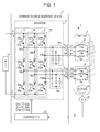
- FIG. 1 is a configuration diagram of a motor driving system including a current source inverter device according to a first embodiment.
- a motor driving system 1 shown in Fig. 1 includes a current source inverter device 2, a three-phase alternating-current (AC) motor 3 (hereinafter, merely referred to as motor 3), a direct-current (DC) source 4, and a position sensor 10.
- AC alternating-current
- DC direct-current
- the current source inverter device 2 converts DC power supplied from the DC source 4 into desirable AC power and outputs the AC power to the motor 3.
- the current source inverter device 2 is not limited to the configuration shown in Fig. 1 .
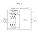
- the current source inverter device 2 may include a converter 17 that converts AC power supplied from a three-phase AC source 4A into DC power and a reactor Ldc as a DC source.
- Fig. 2 is another configuration diagram of the motor driving system 1.
- the current source inverter device 2 includes terminals Tp, T N , T U1 , T U2 , T V1 , T V2 , T W1 , and T W2 , an inverter 11, and a controller 20.
- the terminals T U1 , T V1 , and T W1 are connected with a first three-phase winding 5 included in the motor 3. Also, the terminals Tp and T N are respectively connected with a positive electrode and a negative electrode of the DC source 4. Further, the terminals T U2 , T V2 , and T W2 are connected with a second three-phase winding 6 included in the motor 3.
- the inverter 11 is connected with the DC source 4 through the terminals Tp and T N . Further, the inverter 11 is connected with the motor 3 through the terminals T U1 , T V1 , and T W1 , and the terminals T U2 , T V2 , and T W2 .
- the controller 20 is connected with the position sensor 10.
- the controller 20 controls the inverter 11 and the motor 3.
- the controller 20 selects one of or both the first three-phase winding 5 and the second three-phase winding 6 based on the rotation speed of the motor 3 for each phase of a U-phase, a V-phase, and a W-phase of the motor 3, and determines the selected three-phase winding as a supply target of AC power. Accordingly, the speed control range for the motor 3 can be expanded without switching the winding state of the motor 3.
- the details of the inverter 11 and the controller 20 are more specifically described later.
- the motor 3 includes the first three-phase winding 5, the second three-phase winding 6, and a rotor 9.
- the motor 3 is a motor having three-phase double windings formed of double windings in which stator windings are insulated from each other, for example, an induction motor or a permanent-magnet synchronous motor.
- the number of windings of each of the windings 5a, 5b, and 5c of the first three-phase winding 5, and the number of windings of each of the windings 6a, 6b, and 6c of the second three-phase winding 6 are the same.
- One end of the winding 5a is connected with the terminal T U1
- one end of the winding 5b is connected with the terminal T V1
- one and of the winding 5c is connected with the terminal T W1
- one end of the winding 6a is connected with the terminal T U2
- one end of the winding 6b is connected with the terminal T V2
- one end of the winding 6c is connected with the terminal T W2 .
- the terminals are included in the current source inverter device 2.
- the windings 5a, 5b, and 5c of the first three-phase winding 5 have polarities reverse to the windings 6a, 6b, and 6c of the second three-phase winding 6.
- the two windings corresponding to each phase of the motor 3 are inserted into the same slot of the stator, are electromagnetically densely coupled to each other, and have winding directions with mutually reversed polarities.
- black dots indicate the polarities of the winding directions.
- the rotor 9 is arranged to face a stator (the first three-phase winding 5 and the second three-phase winding 6).
- the other ends of the windings 5a, 5b, and 5c are mutually connected.
- the other ends of the windings 6a, 6b, and 6c are mutually connected.
- the first and second three-phase windings 5 and 6 are formed by Y connection; however, may be formed by delta connection.
- the U-phase, V-phase, and W-phase of the motor 3 are shown as a U1-phase, a V1-phase, and a W1-phase for the first three-phase winding 5, and a U2-phase, a V2-phase, and a W2-phase for the second three-phase winding 6.
- the position sensor 10 is connected with an output shaft of the motor 3.
- the position sensor 10 detects a phase ⁇ of the rotor 9 (hereinafter, referred to as rotor phase ⁇ ) of the motor 3, and outputs the detected phase ⁇ to the controller 20.
- the position sensor 10 is, for example, an encoder or a resolver.
- the inverter 11 includes a switching element unit 12, and filters 16a and 16b.
- the switching element unit 12 includes switching element units 13 to 15.
- the switching element units 13, 14, and 15 respectively correspond to the U-phase, V-phase, and W-phase of the motor 3.
- the switching element units 13 to 15 each have three switching elements connected in series.
- the switching element unit 13 includes three switching elements Q1u, Q2u, and Q3u connected in series.
- the switching element unit 14 includes three switching elements Q1v, Q2v, and Q3v connected in series.
- the switching element unit 15 includes three switching elements Q1w, Q2w, and Q3w connected in series.
- the switching elements Q1u to Q3u, Q1v to Q3v, and Q1w to Q3w are each, for example, a reverse-direction stop insulated gate bipolar transistor (IGBT).
- IGBT insulated gate bipolar transistor
- the switching element Qs is shown by series connection of a transistor and a diode.
- the switching element Qs may be formed by connecting IGBT and a diode in series, or by connecting a metal-oxide-semiconductor field-effect transistor (MOSFET) and a diode in series.
- MOSFET metal-oxide-semiconductor field-effect transistor
- the switching element Qs may be formed by connecting a next-generation semiconductor switching element SiC or GaN and a diode in series.
- the switching element units 13 to 15 each have two nodes among the switching elements Qs, and the two nodes are respectively connected with different two windings with the same phase of the motor 3.
- a node N1u between the switching elements Q1u and Q2u is connected with the U1-phase of the motor 3
- a node N2u between the switching elements Q2u and Q3u is connected with the U2-phase of the motor 3.
- a node N1v between the switching elements Q1v and Q2v is connected with the V1-phase of the motor 3, and a node N2v between the switching elements Q2v and Q3v is connected with the V2-phase of the motor 3.
- a node N1w between the switching elements Q1w and Q2w is connected with the W1-phase of the motor 3, and a node N2w between the switching elements Q2w and Q3w is connected with the W2-phase of the motor 3.
- the filter 16a has capacitors whose one ends are respectively connected with the U1-phase terminal T U1 , the V1-phase terminal T V1 , and the W1-phase terminal T W1 , and the other ends are commonly connected.
- the filter 16b has capacitors whose one ends are respectively connected with the U2-phase terminal T U2 , the V2-phase terminal T V2 , and the W2-phase terminal T W2 , and the other ends are commonly connected.
- the filters 16a and 16b each have a function of removing a high-frequency component of current of each phase output from each of the switching element units 13 to 15.
- the controller 20 When the controller 20 controls the motor 3, the controller 20 generates a gate signal in a control mode corresponding to the rotation speed of the motor 3, and outputs the generated gate signal to the inverter 11. That is, the controller 20 converts the DC power supplied from the DC source 4 into the AC power by the inverter 11, then outputs the AC power to the motor 3, and controls the motor 3.
- the controller 20 switches a control mode between two control modes in accordance with the rotation speed of the motor 3, and controls the inverter 11.
- the controller 20 selects a first control mode in a low-speed region in which the rotation speed of the motor 3 is relatively low, and selects a second control mode in a high-speed region in which the rotation speed of the motor 3 is relatively high. If the controller 20 selects the first control mode, the AC power is supplied in series to the first and second three-phase windings 5 and 6. If the controller 20 selects the second control mode, the AC power is supplied to only one of the first and second three-phase windings 5 and 6. The counter voltage generated in the motor 3 becomes lower in the second control mode than the counter voltage in the first control mode as long as the rotation speed of the motor 3 is the same.
- the current source inverter device 2 can operate in a wide range from the low-speed region to the high-speed region.
- the control modes are successively described. Described below is an example in which the motor 3 is controlled by the controller 20 while a synchronous motor serves as a model, the synchronous motor being controllable by two-axis current having d-axis current (field current or magnetic flux current) and q-axis current (torque current) being orthogonal to each other.
- the controller 20 can control the motor 3 according to other model (control method).
- the controller 20 can control the motor by the control method based on such a model.
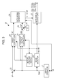
- Fig. 3 is an illustration showing a configuration example of the controller 20.
- the controller 20 includes a speed operator 21, a mode selector 22 (example of a selector and a first selection command unit), a subtracter 23, a speed controller 24, a d-axis current command generator 25, a subtracter 26, a constant-output controller 27, a motor-constant switch 28, a gate-signal generator 29, and a gate-signal output unit 30. These units are specifically described below.
- the speed operator 21 arithmetically operates a rotation speed Ndet of the rotor 9 based on a rotor phase ⁇ output from the position sensor 10, and outputs the rotation speed Ndet to the mode selector 22, the subtracter 23, and the constant-output controller 27.
- the speed operator 21 obtains the rotation speed Ndet, for example, by a change amount per unit time of the rotor phase ⁇ .
- the mode selector 22 selects a control mode from the first control mode and the second control mode based on the rotation speed Ndet. For example, the mode selector 22 selects the first control mode if the rotation speed Ndet is smaller than a set value Ns1, and selects the second control mode if the rotation speed Ndet is the set value Ns1 or greater.
- the mode selector 22 outputs information of the selected control mode to the speed controller 24, the constant-output controller 27, the motor-constant switch 28, and the gate-signal output unit 30.
- Information indicative of the first control mode is, for example, a first mode signal SA with a logical value being “1” and a second mode signal SB with a logical value being “0.”
- information indicative of the second control mode is, for example, a first mode signal SA with a logical value being "0" and a second mode signal SB with a logical value being "1.”
- the first mode signal SA and the second mode signal SB are each merely an example of information of a control mode, and hence the information is not limited to these signals.
- the first mode signal SA and the second mode signal SB are collectively called mode signal SX1.
- the control mode is selected based on the rotation speed Ndet.
- the control mode does not have to be selected based on the rotation speed Ndet, as long as the control mode is selected in accordance with speed information of the motor 3.
- the mode selector 22 may select a control mode based on a speed command.
- the subtracter 23 subtracts the rotation speed Ndet from a speed command N* output from a higher-order device (not shown), and outputs the subtraction result to the speed controller 24.
- the speed controller 24 generates a q-axis current command Iq* so that the difference between the speed command N* and the rotation speed Ndet becomes zero, and outputs the q-axis current command Iq* to the gate-signal generator 29.
- the q-axis current command Iq* is a current command of a q-axis component in a d-q-axis rotation coordinate system synchronized with the rotor phase ⁇ .
- the speed controller 24 can control the q-axis current (torque current) so that output effective power Pe is not changed before and after the switching between the first control mode and the second control mode.
- the speed controller 24 limits the q-axis current command Iq* to a value multiplied by Nbase/Ns1 when the control mode is switched from the first control mode to the second control mode, so that the output effective power Pe is not changed before and after the switching of the control mode.
- the speed controller 24 multiplies the q-axis current command Iq* by Ns1/Nbase when the control mode is switched from the second control mode to the first control mode, so that the output effective power Pe is not changed before and after the switching of the control mode.
- the speed controller 24 detects a switching timing between the first control mode and the second control mode by a change in logical value of the mode signal SX1.
- the d-axis current command generator 25 generates a d-axis current command Id**, and outputs the d-axis current command Id** to the subtracter 26.
- the d-axis current command Id** is, for example, zero if the motor 3 is a synchronous motor, and is, for example, a positive predetermined value if the motor 3 is an induction motor.
- the subtracter 26 subtracts a d-axis field weakening current command value Idrc output from the constant-output controller 27, from the d-axis current command Id**, and outputs a d-axis current command Id* being the subtraction result to the gate-signal generator 29.
- the constant-output controller 27 generates the field weakening current command value Idrc corresponding to the rotation speed Ndet from the speed operator 21 and the logical value of the mode signal SX1 from the mode selector 22, and outputs the field weakening current command value Idrc to the subtracter 26.
- the field weakening current command value Idrc may be generated by using a motor constant from the motor-constant switch 28 (described later).
- the field weakening current command value Idrc is substantially zero until the rotation speed Ndet of the motor 3 reaches a base rotation speed value Nbase. If the rotation speed Ndet exceeds the base rotation speed value Nbase, the constant-output controller 27 changes the field weakening current command value Idrc in a direction in which the field of the motor 3 is weakened in accordance with an increase in rotation speed Ndet.
- the constant-output controller 27 sets the field weakening current command value Idrc at substantial zero. If the rotation speed Ndet of the motor 3 exceeds the set value Ns1, the constant-output controller 27 changes the field weakening current command value Idrc in a direction in which the field of the motor 3 is weakened in accordance with an increase in rotation speed Ndet.
- a region in which the rotation speed Ndet is lower than the base rotation speed value Nbase is occasionally called constant torque region, and a region in which the rotation speed Ndet is equal to or higher than the base rotation speed value Nbase is occasionally called constant output region.
- the method of field weakening control is not limited to the method using the field weakening current command value Idrc, and may execute field weakening control by other known technology.
- the motor-constant switch 28 outputs a motor constant corresponding to the control mode in accordance with the mode signal SX1 from the mode selector 22, to the speed controller 24 and the constant-output controller 27.
- a motor constant corresponding to a control mode is selected from a motor constant for the first control mode and a motor constant for the second control mode, in accordance with the mode signal SX. Accordingly, information of the motor constant used for generation of the q-axis current command Iq* in the speed controller 24 and generation of the field weakening current command value Idrc in the constant-output controller 27 can be properly switched.
- the information of the motor constant corresponds to each control mode, and is, for example, a torque-current conversion coefficient, a stator resistance, a d-axis inductance, a q-axis inductance, or a stator flux linkage.
- a torque-current conversion coefficient for example, a stator resistance, a d-axis inductance, a q-axis inductance, or a stator flux linkage.
- the gate-signal generator 29 generates gate signals G1 to G6 based on the q-axis current command Iq* from the speed controller 24 and the d-axis current command Id* from the subtracter 26, and outputs the gate signals G1 to G6 to the gate-signal output unit 30.
- the gate-signal generator 29 generates current commands Iu*, Iv*, and Iw* of the U-phase, V-phase, and W-phase, based on the q-axis current command Iq*, the d-axis current command Id*, and the rotor phase ⁇ .
- the gate-signal generator 29 generates the current commands Iu*, Iv*, and Iw* according to arithmetic operations in Expressions (1) to (5).
- the gate-signal generator 29 generates line current commands Iuw*, Ivu*, and Iwv* from the current commands Iu*, Iv*, and Iw*. For example, the gate-signal generator 29 generates the current commands Iuw*, Ivu*, and Iwv* according to arithmetic operations in Expressions (6) to (8).
- the gate-signal generator 29 generates the gate signals G1 to G6 based on the line current commands Iuw*, Ivu*, and Iwv*, and outputs the gate signals G1 to G6 to the gate-signal output unit 30.
- the generation of the gate signals G1 to G6 based on the line current commands Iuw*, Ivu*, and Iwv* is a known technology, and, for example, a technology disclosed in Japanese Unexamined Patent Application Publication No. 2012-196119 is used.
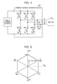
- the gate-signal generator 29 generates the gate signals G1 to G6 equivalent to signals for controlling by PWM control and driving three-phase bridges (see Fig. 4 ) in which two switching elements per phase are connected in series in the inverter 11; and outputs the gate signals G1 to G6 to the gate-signal output unit 30.
- Fig. 4 is an illustration showing a current source inverter device including an inverter having three-phase bridges.
- a current source inverter device 100 shown in Fig. 4 includes three switching elements Qpu, Qpv, and Qpw connected with a positive direct-current (DC) bus P, and three switching elements Qnu, Qnv, and Qnw connected with a negative DC bus N.
- the switching elements Qpu, Qpv, and Qpw may be occasionally written as an upper switching element Qp
- the switching elements Qnu, Qnv, and Qnw may be occasionally written as a lower switching element Qn.
- the gate signals G1 to G6 are gate signals generated so that one of the upper switching elements Qp and one of the lower switching elements Qn are simultaneously in conduction.
- the combination of the switching elements Qp and Qn that are turned ON by the gate signals G1 to G6 is successively shifted as follows. (Qpu, QnV), (Qpu, Qnw), (Qpv, Qnw), (Qpv, Qnu), (Qpw, Qnu), and then (Qpw, Qnv).
- Iuv indicates current flowing in the order from the positive DC bus P, the U-phase of the motor 3, the V-phase of the motor 3, and the negative DC bus N.
- Ivu indicates current flowing in the order from the positive DC bus P, the V-phase of the motor 3, the U-phase of the motor 3, and the negative DC bus N.
- FIG. 5 is an illustration in the form of space vectors showing the current Iuv, Iuw, Ivw, Ivu, Iwu, Iwv, Iuu, Ivv, and Iww of the above-described nine types of current paths when the current is expressed as the current vectors.
- Fig. 6 is a relationship diagram between logical values of the gate signals G1 to G6 and the current vectors Iuv, Iuw, Ivw, Ivu, Iwu, Iwv, Iuu, Ivv, and Iww.
- the switching elements Qpu, Qpv, Qpw, Qnu, Qnv, and Qnw are turned ON if the logical values of the gate signals G1 to G6 are "1.”
- the switching elements Qpu, Qpv, Qpw, Qnu, Qnv, and Qnw are turned OFF if the logical values of the gate signals G1 to G6 are "0.”
- the gate signals G1 to G6 are low level signals if the logical values are "0" and are high level signals if the logical values are "1.”
- the gate-signal generator 29 generates the gate signals G1 to G6 that successively shift the current vectors in the order of Iuv, Iuw, Ivw, Ivu, Iwu, and Iwv, based on the line current commands Iuw*, Ivu*, and Iwv* expressed in Expressions (6) to (8) provided above.
- the gate signals G1 to G6 are signals composed by the space vector method by using neighboring three types of vectors.
- the neighboring three types of vectors have combinations of, for example, (Iuw, Ivw, Iww), (Iwv, Iuv, Ivv), etc.
- the space vector method is known, and hence the detailed description is omitted.
- the gate-signal output unit 30 generates gate signals Glu, G2u, G3u, G1v, G2v, G3v, G1w, G2w, and G3w (hereinafter, occasionally collectively called gate signal Gs) for driving the switching element Qs of the inverter 11 based on the gate signals G1 to G6.
- the gate signals G1u to G3u, G1v to G3v, and G1w to G3w respectively drive the switching elements Q1u to Q3u, Q1v to Q3v, and Q1w to Q3w.
- one of the first and second three-phase windings 5 and 6 serves as a supply target of AC power in the first control mode, and both the first and second three-phase windings 5 and 6 serve as a supply target of AC power in the second control mode.
- an example of a specific configuration of the gate-signal output unit 30 and control of the inverter 11 according to the gate signal Gs are successively described.
- Fig. 7 is an illustration showing a specific configuration example of the gate-signal output unit 30.
- the gate-signal output unit 30 includes a U-phase signal output unit 31, a V-phase signal output unit 32, and a W-phase signal output unit 33.
- the U-phase signal output unit 31 generates the gate signals Glu, G2u, and G3u for controlling the U-phase switching elements Q1u, Q2u, and Q3u.
- the V-phase signal output unit 32 generates the gate signals G1v, G2v, and G3v for controlling the V-phase switching elements Q1v, Q2v, and Q3v.
- the W-phase signal output unit 33 generates the gate signals G1w, G2w, and G3w for controlling the W-phase switching elements Q1w, Q2w, and Q3w.
- the U-phase signal output unit 31 includes logical AND operators (AND circuits) 41 and 42, and a logical OR operator (OR circuit) 43.
- the logical AND operator 41 outputs a logical AND of the gate signal G1 and the first mode signal SA.
- the logical AND operator 42 outputs a logical AND of the gate signal G4 and the second mode signal SB.
- the logical OR operator 43 outputs a logical OR of the output of the logical AND operator 41 and the output of the logical AND operator 42.
- the U-phase signal output unit 31 outputs signals equivalent to the gate signal G1 as the gate signals G1u and G3u, and outputs a signal equivalent to the gate signal G4 as the gate signal G2u.
- the U-phase signal output unit 31 outputs a signal equivalent to the gate signal G1 as the gate signal G1u, and outputs signals equivalent to the gate signal G4 as the gate signals G2u and
- the V-phase signal output unit 32 has a configuration similar to the U-phase signal output unit 31.
- the V-phase signal output unit 32 outputs signals equivalent to the gate signal G2 as the gate signals G1v and G3v, and outputs a signal equivalent to the gate signal G5 as the gate signal G2v in the first control mode. Also, the V-phase signal output unit 32 outputs a signal equivalent to the gate signal G2 as the gate signal G1v, and outputs signals equivalent to the gate signal G5 as the gate signals G2v and G3v in the second control mode.
- the W-phase signal output unit 33 has a configuration similar to the U-phase signal output unit 31.
- the W-phase signal output unit 33 outputs signals equivalent to the gate signal G3 as the gate signals G1w and G3w, and outputs a signal equivalent to the gate signal G6 as the gate signal G2w in the first control mode. Also, the W-phase signal output unit 33 outputs a signal equivalent to the gate signal G3 as the gate signal G1w, and outputs signals equivalent to the gate signal G6 as the gate signals G2w and G3w in the second control mode.
- the U-phase signal output unit 31, the V-phase signal output unit 32, and the W-phase signal output unit 33 are configured, for example, as shown in Fig. 8 .
- Fig. 8 is an illustration showing another specific configuration example of a U-phase signal output unit 31.
- a V-phase signal output unit 32 and a W-phase signal output unit 33 also have configurations similar to the U-phase signal output unit 31 shown in Fig. 8 .
- the U-phase signal output unit 31 includes logical AND operators 44 and 45, and a logical OR operator 46.
- the logical AND operator 44 outputs a logical AND of the gate signal G1 and the first mode signal SA.
- the logical AND operator 45 outputs a logical AND of the gate signal G4 and the second mode signal SB.
- the logical OR operator 46 outputs a logical OR of the output of the logical AND operator 44 and the output of the logical AND operator 45.
- the U-phase signal output unit 31 shown in Fig. 8 outputs signals equivalent to the gate signal G1 as the gate signals G1u and G2u, and outputs a signal equivalent to the gate signal G4 as the gate signal G3u.
- the U-phase signal output unit 31 shown in Fig. 8 outputs a signal equivalent to the gate signal G1 as the gate signal G2u, and outputs signals equivalent to the gate signal G4 as the gate signals G1u and G3u.
- the U-phase signal output unit 31 shown in Fig. 8 outputs a signal equivalent to the gate signal G1 as the gate signal G2u, and outputs signals equivalent to the gate signal G4 as the gate signals G1u and G3u.
- reference signs A to D, and F1 to F3 are added to terminals of each of the U-phase signal output unit 31, the V-phase signal output unit 32, and the W-phase signal output unit 33 to indicate that the V-phase signal output unit 32 and the W-phase signal output unit 33 each have the relationship of functions and terminals equivalent to that of the U-phase signal output unit 31.
- the configuration of the gate-signal output unit 30 is not limited to the configurations shown in Figs. 7 and 8 .
- the gate-signal output unit 30 When the first control mode is selected by the mode selector 22, the gate-signal output unit 30 generates the gate signal Gs for supplying AC power in series from the inverter 11 to each of the first and second three-phase windings 5 and 6, and outputs the gate signal Gs to the inverter 11.
- the pairs of the upper and lower switching elements Qp and Qn are respectively driven by the gate signals G1, G2, and G3, and the middle switching elements Q2u, Q2v, and Q2w are respectively driven by the gate signals G4, G5, and G6.
- Fig. 9 is an illustration showing the flow of the current Iuv flowing from the U-phase to the V-phase.
- the current flows from the positive DC bus P, passes through the switching element Q1u and the U1 terminal T U1 , and thus flows from the current source inverter device 2 to the first three-phase winding 5.
- the current Iuv passes through the U1-phase winding 5a and the V1-phase winding 5b in the first three-phase winding 5, and flows to the V1 terminal T V1 of the current source inverter device 2.
- the current Iuv passes through the V1 terminal T V1 , the switching element Q2v and the V2 terminal T V2 , and thus flows from the current source inverter device 2 to the second three-phase winding 6.
- the current Iuv passes through the V2-phase winding 6b and the U2-phase winding 6a in the second three-phase winding 6, and flows to the U2 terminal T U2 of the current source inverter device 2.
- the current Iuv passes through the U2 terminal T U2 and the switching element Q3u, and flows to the negative DC bus N.
- Fig. 10 is an illustration showing a path of the current Iuv in the motor 3.
- the current flows from the U1-phase to the V1-phase in the first three-phase winding 5, whereas the current flows from the V2-phase to the U2-phase in the second three-phase winding 6.
- the first three-phase winding 5 and the second three-phase winding 6 are arranged so that the polarities of the windings are reverse to each other.
- the current flowing through these three-phase windings 5 and 6 generate a magnet motive force composed with the same polarity.
- the current source inverter device 2 can output a composite current vector having the maximum value that is twice the current vector (see Fig. 5 ) in the current source inverter device 100 (see Fig. 4 ).
- Fig. 11 is an illustration showing space vectors of the current source inverter device 2.
- the current source inverter device 2 can generate a relatively high counter voltage, and can provide a relatively high torque in the low-speed region, as compared with the current source inverter device 100.
- the gate-signal output unit 30 sets the logical value of the gate signal G2v at "0" and the logical value of the gate signal G2u at "1.” Accordingly, the switching element Q2v is turned OFF and the switching element Q3u is turned ON, and current is not supplied from the current source inverter device 2 to the motor 3.
- the gate-signal output unit 30 In contrast, if the mode selector 22 selects the second control mode, the gate-signal output unit 30 generates the gate signal G2 so that AC power is supplied to only one three-phase winding of the first and second three-phase windings 5 and 6, and outputs the gate signal Gs to the inverter 11.
- the upper switching elements Q1u, Q1v, and Q1w are respectively driven by the gate signals G1, G2, and G3, and the pairs of the middle and lower switching elements Qp and Qn, specifically, (Q2u, Q3u), (Q2v and Q3v), and (Q2w, Q3w) are respectively driven by the gate signals G4, G5, and G6.
- Fig. 12 is an illustration showing the flow of the current Iuv being in conduction from the U-phase to the V-phase.
- the current flows from the positive DC bus P, passes through the switching element Q1u and the U1 terminal T U1 , and thus flows from the current source inverter device 2 to the first three-phase winding 5.
- the current Iuv passes through the U1-phase winding 5a and the V1-phase winding 5b in the first three-phase winding 5, and flows to the V1 terminal T V1 of the current source inverter device 2.
- the current Iuv passes through the V1 terminal T V1 and the switching elements Q2v and Q3v, and flows to the negative DC bus N.
- the second control mode AC power is supplied from the inverter 11 only to the first three-phase winding 5.
- the counter power of the motor 3 is halved as compared with the counter power in the first control mode. Accordingly, in the second control mode, the speed range can be expanded as compared with the first control mode.
- the control mode is switched in accordance with the rotation speed Ndet of the motor 3. Accordingly, the speed control range can be expanded for the motor 3.
- the inverter 11 is configured such that 2+1 switching elements Qs are connected in series for each of the U-phase, V-phase, and W-phase of the motor 3, and two nodes among the switching elements Qs are respectively connected with different two windings with the same phase among the windings of the motor 3.
- the controller 20 includes the mode selector 22 that selects one or both of two windings per phase based on the rotation speed of the motor 3, as a supply target of AC power. Accordingly, in the current source inverter device 2, an induced voltage generated in the motor 3 can be reduced, and the speed control range can be expanded similarly to the winding switch method of the related art.
- the current source inverter device according to the second embodiment differs from the current source inverter device 2 according to the first embodiment in that a switching mode for the first control mode and the second control mode is provided.
- a switching mode for the first control mode and the second control mode is provided.
- Fig. 13 is a configuration diagram of a controller of a motor driving system according to a second embodiment.
- a current source inverter device 2A according to the second embodiment executes switching control for repetitively switching the number of windings that supply AC power every phase of the motor 3 with a time ratio corresponding to the rotation speed of the motor 3. Accordingly, the speed control region can be expanded, and additionally a high efficiency region can be expanded.
- a motor driving system 1A according to the second embodiment is similar to the motor driving system 1 except for the configuration of the controller 20A of the current source inverter device 2A. In the following description, the controller 20A is described in detail.
- the controller 20A of the current source inverter device 2A includes a speed operator 21, a mode selector 22A (example of selector, and first and second selection command units), a subtracter 23, a speed controller 24A, a d-axis current command generator 25, a subtracter 26, a constant-output controller 27A, a motor-constant switch 28, a gate-signal generator 29, and a gate-signal output unit 30.
- the mode selector 22A, the speed controller 24A, and the constant-output controller 27A are specifically described.
- the mode selector 22A generates a first mode signal SA and a second mode signal SB with ON ratios corresponding to a rotation speed Ndet output from the speed operator 21, and outputs the first mode signal SA and the second mode signal SB, to the gate-signal output unit 30.
- the mode selector 22A as a first selection command unit, selects a first control mode if Ndet ⁇ Nbase, and selects a second control mode if Ns1 ⁇ Ndet.
- the ON ratio is a ratio with which the logical value becomes "1" for a predetermined unit time (for example, carrier period Tc, described later).
- the mode selector 22A may alternately switch the control mode between the first control mode and the second control mode with the time ratio corresponding to the rotation speed Ndet if Nbase ⁇ Ndet ⁇ Ns1.
- the first selection command unit and the second selection command unit have the same configuration; however, the first selection command unit and the second selection command unit may have different configurations or partly common configurations.
- the time ratio is a temporal ratio with which the first control mode and the second control mode are selected in a predetermined unit time (for example, carrier period Tc, described later).
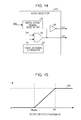
- Fig. 14 is a configuration diagram of the mode selector 22A.
- the mode selector 22A includes a carrier-signal generator 51, a modulation-signal generator 52, a comparator 53, and a logical NOT operator (NOT circuit) 54.
- NOT circuit logical NOT operator
- the carrier-signal generator 51 generates a carrier signal Sc with a predetermined period and outputs the carrier signal Sc.
- the carrier signal Sc is, for example, a triangular waveform signal or a saw waveform signal.
- the period of the carrier signal Sc is desirably a value p (p being a natural number) times a generation period of the gate signals G1 to G6 output from the gate-signal generator 29 with regard to the turn ON and OFF periods of the switching element Qs, and is desirably synchronized with the gate signals G1 to G6.
- the modulation-signal generator 52 generates a modulation signal Sm having a magnitude corresponding to the rotation speed Ndet output from the speed operator 21.
- Fig. 15 is a relationship diagram of the rotation speed Ndet and the magnitude of the modulation signal Sm. As shown in Fig. 15 , the magnitude of the modulation signal Sm is "0" if Ndet ⁇ Nbase, and the magnitude of the modulation signal Sm is "1" if Ns1 ⁇ Ndet. In contrast, the magnitude of the modulation signal Sm is (Ndet - Nbase)/(Ns1 - Nbase) between "0" and "1" if Nbase ⁇ Ndet ⁇ Ns1.
- the comparator 53 compares the carrier signal Sc with the modulation signal Sm, and generates the second mode signal SB. To be specific, the comparator 53 outputs the first mode signal SA having the logical value being "1" if the modulation signal Sm is smaller than the carrier signal Sc, and the comparator 53 outputs the second mode signal SB having the logical value being "0" if the modulation signal Sm is equal to or greater than the carrier signal Sc.
- the logical NOT operator 54 receives an input of the first mode signal SA, and outputs the second mode signal SB, in which the logical value of the first mode signal SA is inverted.
- Fig. 16 is an illustration showing an example of waveforms of the carrier signal Sc, modulation signal Sm, first mode signal SA, and second mode signal SB if Nbase ⁇ Ndet ⁇ Ns1.
- the logical value of the first mode signal SA becomes “1” for a first period T1 and becomes “0” for a second period T2 every carrier period Tc.
- the logical value of the second mode signal SB becomes "0" for the first period T1 and becomes "1” for the second period T2 every carrier period Tc.
- the current source inverter device 2A executes the switching mode in which the first control mode and the second control mode are alternately turned ON and OFF if Nbase ⁇ Ndet ⁇ Ns1.
- the current source inverter device 2A operates in the first control mode if Ndet ⁇ Nbase, and operates in the second control mode if Ns1 ⁇ Ndet.
- Fig. 17 is a relationship diagram of the time ratio of the first control mode and the time ratio of the second control mode when the motor 3 is accelerated. As shown in Fig. 17 , when the motor 3 is accelerated or decelerated, the time ratio of the first control mode and the time ratio of the second control mode are continuously changed between 0% and 100%.
- the speed controller 24A ( Fig. 13 ) can limit, for example, the q-axis current command Iq* to a value multiplied by (Nbase + Ns1)/(2Ns1) within the range of Nbase ⁇ Ndet ⁇ Ns1. Also, if the rotation speed Ndet reaches the set value Ns1, the speed controller 24A can limit the q-axis current command Iq* to a value multiplied by Nbase/Ns1, similarly to the first embodiment.
- the constant-output controller 27A ( Fig. 13 ) sets, for example, the field weakening current command value Idrc to be a half of the d-axis current command that is immediately before the rotation speed Ndet increases and reaches the set value Ns1 in the first embodiment, within the range of the Nbase ⁇ Ndet ⁇ Ns1. If the rotation speed Ndet reaches the set value Ns1, the constant-output controller 27A deactivates the field weakening control, and sets the field weakening current command value Idrc at substantially zero similarly to the first embodiment.
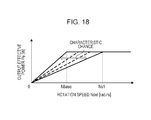
- Fig. 18 is a relationship diagram of the rotation speed Ndet and the output effective power Pe.
- the speed control range can be expanded and the high efficiency region can be expanded.
- a current source inverter device according to a third embodiment is described.
- the current source inverter devices 2 and 2A of the first and second embodiments each operate in the first and second control modes; however, the current source inverter device according to the third embodiment operates in a third control mode in addition to the first and second control modes.
- points different from the motor driving system 1 according to the first embodiment are mainly described, and components having similar functions to those of the first embodiment are given with the same reference signs and redundant description is omitted.
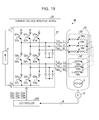
- Fig. 19 is a configuration diagram of a motor driving system 1B according to the third embodiment.
- the motor driving system 1B according to the third embodiment includes a current source inverter device 2B, a motor 3B, and a DC source 4.
- the current source inverter device 2B includes an inverter 11 and a controller 20B.
- the inverter 11 has a configuration similar to the inverter 11 according to the first embodiment.
- the controller 20B differs from the controller 20 in that the controller 20B executes the third control mode in addition to the first and second control modes.
- the motor 3B differs from the motor 3 in that the number of windings of a first three-phase winding 5B is twice the number of windings of a second three-phase winding 6B. That is, windings 5Ba to 5Bc each have a number of windings that is twice the number of windings of each of windings 6Ba to 6Bc.
- the controller 20B supplies power to the first and second three-phase windings 5B and 6B in the first control mode.
- the controller 20B supplies power to the first three-phase winding 5B in the second control mode.
- the controller 20B supplies power to the second three-phase winding 6B in the third control mode.
- the speed control range can be further expanded as compared with the current source inverter device 2.
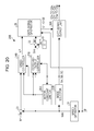
- Fig. 20 is an illustration showing a configuration example of the controller 20B.
- the controller 20B includes a speed operator 21, a mode selector 22B (example of selector and first selection command unit), a subtracter 23, a speed controller 24B, a d-axis current command generator 25, a subtracter 26, a constant-output controller 27B, a motor-constant switch 28B, a gate-signal generator 29, and a gate-signal output unit 30B.
- the mode selector 22B, the speed controller 24B, the constant-output controller 27B, the motor-constant switch 28B, and the gate-signal output unit 30B are specifically described.
- the mode selector 22B selects one control mode from the first to third control modes based on a rotation speed Ndet and set values Ns1 and Ns2. To be specific, the mode selector 22B selects the first control mode if Ndet ⁇ Ns1, selects the second control mode if Ns1 ⁇ Ndet ⁇ Ns2, and selects the third control mode if Ins2 ⁇ Ndet. The mode selector 22B outputs information of the selected control mode to the speed controller 24B, the constant-output controller 27B, the motor-constant switch 28B, and the gate-signal output unit 30B.
- Information indicative of the first control mode is, for example, a first mode signal SA with a logical value being "1,” and second and third mode signals SB and SC with logical values being “0.”
- information indicative of the second control mode is, for example, the first and third mode signal SA and SC with logical values being "0" and the second mode signal SB with a logical value being "1.”
- information indicative of the third control mode is, for example, the third mode signal SC with a logical value being "1" and the first and second mode signals SA and SB with logical values being "0.”
- the first to third mode signals SA, SB, and SC are each merely an example of information of a control mode, and hence the information is not limited to these signals.
- the first to third mode signals SA, SB, and SC are collectively written as mode signal SX2.
- the speed controller 24B generates a q-axis current command Iq* so that the difference between a speed command N* and a rotation speed Ndet becomes zero, and outputs the q-axis current command Iq* to the gate-signal generator 29.
- the speed controller 24B holds the q-axis current command Iq* constant similarly to the speed controller 24 if field weakening control is being executed by the constant-output controller 27B.
- the speed controller 24B can control q-axis current (torque current) so that output effective power Pe is not changed before and after the switching of the control mode similarly to the speed controller 24.
- the constant-output controller 27B generates a field weakening current command value Idrc corresponding to the rotation speed Ndet from the speed operator 21 and the logical value of the mode signal SX2 from the mode selector 22B, and outputs the field weakening current command value Idrc to the subtracter 26.
- the constant-output controller 27B sets the field weakening current command value Idrc at substantially zero at the switching from the first control mode to the second control mode and at the switching from the second control mode to the third control mode.
- the constant-output controller 27B changes the field weakening current command value Idrc in a direction in which the field of the motor 3B is weakened in accordance with an increase in rotation speed Ndet.
- the motor-constant switch 28B selects a motor constant of a control mode corresponding to the mode signal SX2 among motor constants for the first to third control modes, in accordance with the mode signal SX2 from the mode selector 22B, and outputs the motor constant to the speed controller 24B and the constant-output controller 27B. Accordingly, information of the motor constant used for generation of the q-axis current command Iq* in the speed controller 24B and generation of the field weakening current command value Idrc in the constant-output controller 27B can be properly switched.
- the gate-signal output unit 30B generates a gate signal Gs from the gate signals G1 to G6, in accordance with the mode signal SX2 from the mode selector 22B. With this gate signal Gs, the first and second three-phase windings 5B and 6B become supply targets of AC power in the first control mode, the first three-phase winding 5B becomes a supply target of AC power in the second control mode, and the second three-phase winding 6B becomes a supply target of AC power in the third control mode.
- Fig. 21 is an illustration showing a specific configuration example of the gate-signal output unit 30B.
- the gate-signal output unit 30B includes a U-phase signal output unit 31B, a V-phase signal output unit 32B, and a W-phase signal output unit 33B.
- the U-phase signal output unit 31B generates gate signals Glu, G2u, and G3u
- the V-phase signal output unit 32B generates gate signals G1v, G2v, and G3v
- the W-phase signal output unit 33B generates gate signals G1w, G2w, and G3w.
- the U-phase signal output unit 31B includes logical AND operators 61 to 66, and logical OR circuits 67 and 68.
- the logical AND operators 61 and 64 each output a logical AND of the gate signal G1 and the first mode signal SA.
- the logical AND operator 62 outputs a logical AND of the gate signal G1 and the second mode signal SB.
- the logical AND operator 63 outputs a logical AND of the gate signal G4 and the third mode signal SC.
- the logical AND operator 65 outputs a logical AND of the gate signal G4 and the second mode signal SB.
- the logical AND operator 66 outputs a logical AND of the gate signal G1 and the third mode signal SC.
- the logical OR circuit 67 outputs a logical OR of outputs of the logical AND operators 61 to 63.
- the logical OR circuit 68 outputs a logical OR of outputs of the logical AND operators 64 to 66.
- the U-phase signal output unit 31B outputs signals equivalent to the gate signal G1 as the gate signals G1u and G3u, and outputs a signal equivalent to the gate signal G4 as the gate signal G2u.
- the logical values of the first to third mode signals SA to SC are respectively "0,” "1,” and "0.”
- the U-phase signal output unit 31B outputs a signal equivalent to the gate signal G1 as the gate signal Glu, and outputs signals equivalent to the gate signal G4 as the gate signals G2u and G3u.
- the logical values of the first to third mode signals SA to SC are respectively "0,” “0,” and “1.”
- the U-phase signal output unit 31B outputs a signal equivalent to the gate signal G1 as the gate signal G3u, and outputs signals equivalent to the gate signal G4 as the gate signals G1u and G2u.
- the V-phase signal output unit 32B has a configuration similar to the U-phase signal output unit 31B.
- the V-phase signal output unit 32B outputs signals equivalent to the gate signal G2 as the gate signals G1v and G3v, and outputs a signal equivalent to the gate signal G5 as the gate signal G2v in the first control mode.
- the V-phase signal output unit 32B outputs a signal equivalent to the gate signal G2 as the gate signal G1v, and outputs signals equivalent to the gate signal G5 as the gate signals G2v and G3v in the second control mode.
- the V-phase signal output unit 32B outputs a signal equivalent to the gate signal G2 as the gate signal G3v, and outputs signals equivalent to the gate signal G5 as the gate signals G1v and G2v in the third control mode.
- the W-phase signal output unit 33B has a configuration similar to the U-phase signal output unit 31B.
- the W-phase signal output unit 33B outputs signals equivalent to the gate signal G3 as the gate signals G1w and G3w, and outputs a signal equivalent to the gate signal G6 as the gate signal G2w in the first control mode.
- the W-phase signal output unit 33B outputs a signal equivalent to the gate signal G3 as the gate signal G1w, and outputs signals equivalent to the gate signal G6 as the gate signals G2w and G3w in the second control mode.
- the W-phase signal output unit 33B outputs a signal equivalent to the gate signal G3 as the gate signal G3w, and outputs signals equivalent to the gate signal G6 as the gate signals G1w and G2w in the third control mode.
- reference signs A to D, and F1 to F3 are added to terminals of each of the U-phase signal output unit 31B, the V-phase signal output unit 32B, and the W-phase signal output unit 33B to indicate that the V-phase signal output unit 32B and the W-phase signal output unit 33B each have the relationship of functions and terminals equivalent to that of the U-phase signal output unit 31B.
- the motor driving system 1B includes the motor 3B having the first and second three-phase windings 5B and 6B, the numbers of windings being different from each other.
- the controller 20B selects a supply target of AC power per phase based on the speed of the motor 3B. That is, the controller 20B sets the supply target(s) of AC power at the first and second three-phase windings 5B and 6B in the first control mode, at the first three-phase winding 5B in the second control mode, and at the second three-phase winding 6B in the third control mode. Accordingly, in the current source inverter device 2B, the induced voltage generated in the motor 3B can be reduced by two steps, and the speed control range can be further expanded.
- a current source inverter device according to a fourth embodiment is described.
- the current source inverter devices 2, 2A, and 2B according to the first to third embodiments operate the motors 3 and 3B each having two windings per phase.
- the current source inverter device according to the fourth embodiment operates a motor having four windings per phase.
- points different from the motor driving system 1 according to the first embodiment are mainly described, and components having similar functions to those of the first embodiment are given with the same reference signs and redundant description is omitted.
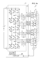
- Fig. 22 is a configuration diagram of a motor driving system according to the fourth embodiment.
- a motor driving system 1C according to the fourth embodiment includes a current source inverter device 2C, a motor 3C, and a DC source 4.
- the motor 3C is a three-phase quadruple-winding motor formed of quadruple windings in which stator windings are insulated from each other, and has first to fourth three-phase windings 5C to 8C.
- the three-phase windings 5C to 8C have the same number of windings. However, the numbers of windings may be different from each other like the motor 3B according to the third embodiment.
- Respective windings 5Ca, 5Cb, and 5Cc of the first three-phase winging 5C and respective windings 7Ca, 7Cb, and 7Cc of the third three-phase winding 7C have the same polarity.
- Respective windings 6Ca, 6Cb, and 6Cc of the second three-phase winging 6C and respective windings 8Ca, 8Cb, and 8Cc of the fourth three-phase winding 8C have the same polarity.
- the four windings corresponding to each phase of the motor 3C are inserted into the same slot of the stator, are electromagnetically densely coupled to each other, and have winding directions with alternately reversed polarities. In Fig. 22 , black dots show the polarities of the winding directions.
- the current source inverter device 2C includes terminals T U1 , T U2 , T V1 , T V2 , T W1 , T W2 , T U3 , T U4 , T V3 , T V4 , T W3 , and T W4 , an inverter 11C, and a controller 20C.
- the terminals T U1 , T V1 , and T W1 are connected with the first three-phase winding 5C included in the motor 3C.
- the terminals T U2 , T V2 , and T W2 are connected with the second three-phase winding 6C included in the motor 3C.
- terminals T U3 , T V3 , and T W3 are connected with the third three-phase winding 7C included in the motor 3C.
- the terminals T U4 , T V4 , and T W4 are connected with the fourth three-phase winding 8C included in the motor 3C.
- the inverter 11C includes a switching element unit 12C, and filters 16a to 16d.
- the switching element unit 12C includes switching element units 13C to 15C.
- the switching element unit 13C is provided for the U-phase of the motor 3C.
- the switching element unit 14C is provided for the V-phase of the motor 3C.
- the switching element unit 15C is provided for the W-phase of the motor 3C.
- the switching element units 13C to 15C each have five switching elements connected in series.
- the switching element unit 13C is formed such that five switching elements Q1u to Q5u are connected in series.
- the switching element unit 14C is formed such that five switching elements Q1v to Q5v are connected in series.
- the switching element unit 15C is formed such that five switching elements Q1w to Q5w are connected in series.
- the switching elements Q4u, Q5u, Q4v, Q5v, Q4w, and Q5w have configurations similar to the switching element Q1u or the like. Hereinafter, these switching elements may be occasionally collectively called switching element Qs.
- the switching element units 13C to 15C each have four nodes among the switching elements Qs, and the four nodes are respectively connected with different four windings with the same phase of the motor 3C.
- nodes N1u, N2u, N3u, and N4u are respectively connected with a U1-phase, a U2-phase, a U3-phase, and a U4-phase of the motor 3C.
- nodes N1v, N2v, N3v, and N4v are respectively connected with a V1-phase, a V2-phase, a V3-phase, and a V4-phase of the motor 3C.
- nodes N1w, N2w, N3w, and N4w are respectively connected with a W1-phase, a W2-phase, a W3-phase, and a W4-phase of the motor 3C.
- the filter 16a and the filter 16b have configurations similar to the first embodiment.
- One ends of capacitors of the filter 16c are respectively connected with the terminals T U3 , T V3 , and T W3 , and the other ends of the capacitors are commonly connected.
- One ends of capacitors of the filter 16d are respectively connected with the terminals T U4 , T V4 , and T W4 , and the other ends of the capacitors are commonly connected.
- the controller 20C generates a gate signal in a control mode corresponding to the rotation speed of the motor 3C among first to fourth control modes, and outputs the gate signal to the inverter 11C.
- the controller 20C supplies AC power to four windings per phase of the motor 3C in the first control mode, and supplies AC power to three windings per phase of the motor 3C in the second control mode.
- the controller 20C supplies AC power to two windings per phase of the motor 3C in the third control mode, and supplies AC power to one winding per phase of the motor 3C in the fourth control mode.
- the controller 20C switches the control mode from the first control mode to the second control mode, the third control mode, and then the fourth control mode as the rotation speed of the motor 3C increases, and thus executes switching for reducing the induced voltage of the motor 3C. Accordingly, the current source inverter device 2C can expand the speed control range.
- Fig. 23 is an illustration showing a configuration example of the controller 20C.
- the controller 20C includes a speed operator 21, a mode selector 22C (example of selector and first selection command unit), a subtracter 23, a speed controller 24C, a d-axis current command generator 25, a subtracter 26, a constant-output controller 27C, a motor-constant switch 28C, a gate-signal generator 29, and a gate-signal output unit 30C.
- the mode selector 22C, the speed controller 24C, the constant-output controller 27C, the motor-constant switch 28C, and the gate-signal output unit 30C are specifically described.
- the mode selector 22C selects one control mode from the first to fourth control modes based on a rotation speed Ndet and set values Ns1, Ns2, and Ns3. To be specific, the mode selector 22C selects the first control mode if Ndet
- the mode selector 22C selects the third control mode if Ns2 ⁇ Ndet ⁇ Ns3, and selects the fourth control mode if Ns3 ⁇ Ndet.
- Information indicative of the first control mode is, for example, a first mode signal SA with a logical value being “1,” and second to fourth mode signals SB, SC, and SD with logical values being “0.”
- information indicative of the second control mode is, for example, the second mode signal SB with a logical value being “1” and the first, third, and fourth mode signals SA, SC, and SD with logical values being “0.”
- information indicative of the third control mode is, for example, the third mode signal SC with a logical value being "1" and the first, second, and fourth mode signals SA, SB, and SD with logical values being "1.”
- information indicative of the fourth control mode is, for example, the fourth mode signal SD with a logical value being "1" and the first to third mode signals SA, SB, and SC with logical values being "1.”
- the first to fourth mode signals SA, SB, SC, and SD are each merely an example of information of a control mode, and hence the information is not limited to these signals.
- the first to fourth mode signals SA, SB, SC, and SD are collectively written as mode signal SX3.
- the control mode is selected based on the rotation speed Ndet.
- the control mode does not have to be selected based on the rotation speed Ndet, as long as the control mode is selected in accordance with speed information of the motor 3C similarly to the mode selector 22.
- the speed controller 24C generates a q-axis current command Iq* so that the difference between a speed command N* and the rotation speed Ndet becomes zero, and outputs the q-axis current command Iq* to the gate-signal generator 29.
- the speed controller 24C holds the q-axis current command Iq* constant similarly to the speed controller 24 if field weakening control is executed by the constant-output controller 27C.
- the speed controller 24C can control q-axis current (torque current) so that output effective power Pe is not changed before and after the switching of the control mode similarly to the speed controller 24.
- the constant-output controller 27C generates a field weakening current command value Idrc corresponding to the rotation speed Ndet from the speed operator 21 and the logical value of the mode signal SX3 from the mode selector 22C, and outputs the field weakening current command value Idrc to the subtracter 26.
- the constant-output controller 27C sets the field weakening current command value Idrc at substantially zero at the switching from the first control mode to the second control mode, at the switching from the second control mode to the third control mode, and at the switching from the third control mode to the fourth control mode.
- the constant-output controller 27C changes the field weakening current command value Idrc in a direction in which the field of the motor 3C is weakened in accordance with an increase in rotation speed Ndet.
- the motor-constant switch 28C selects a motor constant of a corresponding control mode among motor constants for the first to fourth control modes, in accordance with the mode signal SX3 from the mode selector 22C, and outputs the motor constant to the speed controller 24C and the constant-output controller 27C. Accordingly, information of the motor constant used for generation of the q-axis current command Iq* in the speed controller 24C and generation of the field weakening current command value Idrc in the constant-output controller 27C can be properly switched.
- the gate-signal output unit 30C generates gate signals G1u to G5u, G1v to G5v, and G1w to G5w (hereinafter, occasionally collectively called gate signal Gs) for driving the switching element Qs of the inverter 11C in accordance with the mode signal SX3 from the mode selector 22C.
- the gate signals G1u to G5u, G1v to G5v, and G1w to G5w respectively drive the switching elements Q1u to Q5u, Q1v to Q5v, and Q1w to Q5w.
- the gate-signal output unit 30C When the first control mode is selected by the mode selector 22C, the gate-signal output unit 30C generates the gate signal Gs for supplying AC power in series from the inverter 11C to each of the first to fourth three-phase windings 5C to 8C, and outputs the gate signal Gs to the inverter 11C.
- the upper-middle and lower-middle switching elements Q2u, Q2v, Q2w, Q4u, Q4v, and Q4w are driven by the corresponding gate signals G4, G5, and G6, and the other switching elements Qs are driven by the corresponding gate signals G1, G2, and G3. Accordingly, AC power is supplied from the inverter 11C to the first to fourth three-phase windings 5C to 8C.
- the gate-signal output unit 30C outputs the gate signals G1u, G2v, G3u, G4v, and G5u with logical values being "1," and outputs the other gate signals Gs with logical values being "0.”
- the upper-middle, lower-middle, and lowermost switching elements Q2u, Q2v, Q2w, Q4u, Q4v, Q4w, Q5u, Q5v, and Q5w are driven by the corresponding gate signals G4, G5, and G6, and the other switching elements Qs are driven by the corresponding gate signals G1, G2, and G3. Accordingly, AC power is supplied from the inverter 11C only to the first to third three-phase windings 5C to 7C.
- the gate-signal output unit 30C when the current Iuv is applied in the second control mode, the gate-signal output unit 30C outputs the gate signals G1u, G2v, G3u, G4v, and G5v with logical values being "1," and outputs the other gate signals Gs with logical values being "0.”
- the upper-middle switching elements Q2u, Q2v, and Q2w are driven by the corresponding gate signals G4, G5, and G6, and the other switching elements Qs are driven by the corresponding gate signals G1, G2, and G3. Accordingly, AC power is supplied from the inverter 11C only to the first and second three-phase windings 5C and 6C.
- the gate-signal output unit 30C outputs the gate signals G1u, G2v, and G3u to G5u with logical values being "1," and outputs the other gate signals Gs with logical values being "0.”
- the uppermost switching elements Q1u, Q1v, and Q1w are driven by the corresponding gate signals G1, G2, and G3, and the other switching elements Qs are driven by the corresponding gate signals G4, G5, and G6. Accordingly, AC power is supplied from the inverter 11C only to the first three-phase winding 5C.
- the gate-signal output unit 30C outputs the gate signals G1u, and G2v to G5v with logical values being "1," and outputs the other gate signals Gs with logical values being "0.”
- the configuration of the gate-signal output unit 30C is not limited to the above-described configuration as long as the gate-signal output unit 30C can supply AC power individually to windings in accordance with the control mode.
- the gate-signal output unit 30C may cause the switching elements Q1u to Q4u, Q1v to Q4v, and Q1w to Q4w except the lowermost switching elements to be driven by the corresponding gate signals G1, G2, and G3, and the lowermost switching elements Q5u, Q5v, and Q5w may be driven by the corresponding gate signals G4, G5, and G6.
- the current source inverter device 2C switches the control mode from the first control mode to the second control mode, the third control mode, and then the fourth control mode as the rotation speed of the motor 3C increases, and thus executes switching for reducing the induced voltage of the motor 3C. Accordingly, the current source inverter device 2C can expand the speed control range.
- a motor having a number m of windings per phase can be controlled.
- the control target is not limited to the motor 3, 3C having two or four windings per phase, and the control target may be a motor having three, or five or more windings per phase.
- a current source inverter device According to a fifth embodiment, a current source inverter device according to a fifth embodiment is described.
- the current source inverter devices 2, and 2A to 2C according to the above-described embodiments operate the motors 3, 3B, and 3C each having a number m (m being an integer of 2 or greater) of windings per phase.
- the current source inverter device according to the fifth embodiment operates a number n (n being an integer of 2 or greater) of motors each having the number m of windings per phase.
- Fig. 24 is a configuration diagram of a motor driving system according to the fifth embodiment.
- a motor driving system 1D according to the fifth embodiment includes a current source inverter device 2D, motors 3D and 3E, and a DC source 4.
- the motors 3D and 3E each have a configuration similar to the motor 3.
- a position sensor 10 detects the rotation speed of the motor 3E; however, may detect the rotation speed of the motor 3D.
- the current source inverter device 2D synchronizes the two motors 3D and 3E at the same speed and controls the motors 3D and 3E. Control of the motors 3D and 3E by the current source inverter device 2D is similar to the control of the motor 3 by the current source inverter device 2.
- An inverter 11C and a controller 20D are provided.
- the inverter 11C has a configuration similar to the inverter 11C according to the fourth embodiment.
- the controller 20D controls the inverter 11C in one operation mode of first and second control modes.
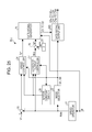
- Fig. 25 is an illustration showing a configuration example of the controller 20D.
- the controller 20D includes a speed operator 21, a mode selector 22 (example of selector and first selection command unit), a subtracter 23, a speed controller 24, a d-axis current command generator 25, a subtracter 26, a constant-output controller 27, a motor-constant switch 28, a gate-signal generator 29, and a gate-signal output unit 30D.
- the gate-signal output unit 30D When the first control mode is selected by the mode selector 22, the gate-signal output unit 30D generates the gate signal Gs for supplying AC power in series from the inverter 11C to three-phase windings 5 and 6 of each of the two motors 3D and 3E, and outputs the gate signal Gs to the inverter 11C.
- the upper-middle and lower-middle switching elements Q2u, Q2v, Q2w, Q4u, Q4v, and Q4w are driven by the corresponding gate signals G4, G5, and G6, and the other switching elements Qs are driven by the corresponding gate signals G1, G2, and G3. Accordingly, AC power is supplied from the inverter 11C to the two three-phase windings 5 and 6 of each of the motors 3D and 3E.
- the gate-signal output unit 30D when current Iuv is applied in the first control mode, the gate-signal output unit 30D outputs the gate signals G1u, G2v, G3u, G4v, and G5u with logical values being "1," and outputs the other gate signals Gs with logical values being "0.”
- the upper-middle and middle switching elements Q2u, Q2v, Q2w, Q3u, Q3v, and Q3w are driven by the corresponding gate signals G4, G5, and G6, and the other switching elements Qs are driven by the corresponding gate signals G1, G2, and G3. Accordingly, AC power is supplied from the inverter 11C only to the three-phase windings 5 of the motors 3D and 3E.
- the gate-signal output unit 30D outputs the gate signals G1u, G2v, G3v, G4u, and G5u with logical values being "1," and outputs the other gate signals Gs with logical values being "0.”
- the gate-signal output unit 30D may also generate the gate signals G1u to G5u, G1v to G5v, and G1w to G5w to supply AC power from the inverter 11C only to the second three-phase windings 6 of the motors 3D and 3E in the second control mode.
- the current source inverter device 2D can expand the speed control range while operating the two motors 3D and 3E each having two windings per phase. If a switching unit is formed by connecting a number nxm+1 (n, m each being integers of 2 or greater) of switching elements in series, a number n of motors each having a number m of windings per phase can be controlled.
- the control target is not limited to the two motors 3D and 3E each having the two windings per phase.
- the current source inverter device 2D may alternately switch the three-phase windings, as a supply target of AC power, between the three-phase windings of the motor 3D and the three-phase windings of the motor 3E every predetermined period. Accordingly, the current and torque of the two motors 3D and 3E can be balanced. By increasing or decreasing the number of three-phase windings to be selected as the supply target of AC power, torque control and speed control in wide ranges can be executed.
- the current source inverter device 2D may alternately switch a combination of three three-phase windings as a supply target of AC power among different combinations of three-phase windings every predetermined period.
- the controller 20D supplies AC power to the first and second three-phase windings 5 and 6 of the motor 3D and the first three-phase winding 5 of the motor 3E in the first control mode, and the controller 20D supplies AC power to the first three-phase winding 5 of the motor 3D and the first and second three-phase windings 5 and 6 of the motor 3E in the second control mode.
- the controller 20D alternately switches the control mode between the first control mode and the second control mode every predetermined period, so as to equalize average currents and average torques applied to the two motors 3D and 3E.
- the gate-signal output unit 30D switches a combination of three three-phase windings among different combinations as a supply target of AC power in accordance with the control mode.
- the mode selector 22 outputs the first mode signal SA and the second mode signal SB with the ON ratio of 50%.
- the current source inverter device 2D may alternately switch a motor as a supply target of AC power between the motor 3D and the motor 3E every predetermined period.
- the controller 20D supplies AC power to the first and second three-phase windings 5 and 6 of the motor 3D in the first control mode, and the controller 20D supplies AC power to the first and second three-phase windings 5 and 6 of the motor 3E in the second control mode.
- the controller 20D alternately switches the control mode between the first control mode and the second control mode every predetermined period, so as to equalize average currents and average torques applied to the two motors 3D and 3E.
- the gate-signal output unit 30D switches a motor between the motor 3D and the motor 3E as a supply target of AC power in accordance with the control mode. Also, in the controller 20D, the mode selector 22 outputs the first mode signal SA and the second mode signal SB with the ON ratio of 50%.
- the current source inverter device 2D may alternately switch a motor as a supply target of AC power between a single three-phase winding of the motor 3D and a single three-phase winding of the motor 3E every predetermined period.
- the controller 20D supplies AC power to the first three-phase winding 5 of the motor 3D in the first control mode, and the controller 20D supplies AC power to the first three-phase winding 5 of the motor 3E in the second control mode.
- the controller 20D alternately switches the control mode between the first control mode and the second control mode every predetermined period, so as to equalize average currents and average torques applied to the two motors 3D and 3E.
- the gate-signal output unit 30D switches a three-phase winding between a single three-phase winding of the motor 3D and a single three-phase winding of the motor 3E as a supply target of AC power in accordance with the control mode. Also, in the controller 20D, the mode selector 22 outputs the first mode signal SA and the second mode signal SB with the ON ratio of 50%.
- the controllers 20, and 20A to 20D are each described as a unit that controls a motor 3 in a constant torque region and a constant output region. However, control only in the constant torque region can be performed. In this case, for example, the controllers 20, and 20A to 20D each may control the motor 3 according to a desired purpose of use including a large torque at low speed or when stopped and performance of highspeed operation.
Landscapes
- Engineering & Computer Science (AREA)
- Power Engineering (AREA)
- Control Of Ac Motors In General (AREA)
- Inverter Devices (AREA)
Abstract
Description
- The embodiments disclosed therein relate to current source inverter devices.
- There has been known a technology that switches a stator winding of an alternating-current (AC) motor from a low-speed winding to a high-speed winding by a winding switch if the rotation speed of the AC motor becomes high speed.
- The technology reduces a counter voltage that is generated in the AC motor at high speed by switching the stator winding from the low-speed winding to the high-speed winding. Accordingly, the speed control range is expanded, and operation in a wide range from a low-speed region to a high-speed region becomes available (for example, see Japanese Patent No.
3948009 - However, the technology of the related art that switches the winding state of the AC motor uses, for example, a winding switch circuit. Further, a plurality of terminals and a plurality of wirings are provided for connection between the AC motor and the winding switch circuit. Therefore, there may be problems in viewpoints of reduction in size and reduction in weight of the AC motor.
- An aspect of the disclosure is made in light of the above-described situation, and it is an object of the disclosure to provide a current source inverter device that can expand a speed control range for an alternating-current motor, by selecting a winding, to which power is supplied, in the inverter device, without switching a winding state of the alternating-current motor.
- According to an aspect of the disclosure, there is provided a current source inverter device including an inverter and a controller. The inverter supplies alternating-current power to a number n (n being an integer of 1 or greater) of alternating-current motors each having a number m (m being an integer of 2 or greater) of windings per phase. The controller controls the inverter and the alternating-current motor. The inverter includes a switching unit, in which a number nxm+1 of switching elements per phase of the alternating-current motor are connected in series, and a number nxm of nodes among the switching elements are respectively connected with a number nxm of different windings with the same phase among the windings of the number n of the alternating-current motors. The controller includes a selector that selects at least one winding as a supply target of the alternating-current power from the number nxm of the windings based on a rotation speed of the alternating-current motor.
-
-
Fig. 1 is a configuration diagram of a motor driving system including a current source inverter device according to a first embodiment. -
Fig. 2 is another configuration diagram of the motor driving system. -
Fig. 3 is an illustration showing a configuration example of a controller shown inFig. 1 . -
Fig. 4 is an illustration showing a current source inverter device including an inverter having three-phase bridges. -
Fig. 5 is an illustration in the form of space vectors expressing current of nine types of current paths as current vectors. -
Fig. 6 is a relationship diagram of logical values of gate signals and current vectors. -
Fig. 7 is an illustration showing a specific configuration example of a gate-signal output unit. -
Fig. 8 is an illustration showing another specific configuration example of each phase-signal output unit. -
Fig. 9 is an illustration showing the flow of current flowing from the U-phase to the V-phase in a first control mode. -
Fig. 10 is an illustration showing current paths in the motor in a state shown inFig. 9 . -
Fig. 11 is an illustration showing space vectors in the first control mode. -
Fig. 12 is an illustration showing the flow of current flowing from the U-phase to the V-phase in a second control mode. -
Fig. 13 is a configuration diagram of a controller of a motor driving system according to a second embodiment. -
Fig. 14 is a configuration diagram of a mode selector shown inFig. 13 . -
Fig. 15 is a relationship diagram of the rotation speed and the magnitude of a modulation signal. -
Fig. 16 is an illustration showing an example of waveforms of a carrier signal, a modulation signal, a first mode signal, and a second mode signal. -
Fig. 17 is a relationship diagram of the time ratio of the first control mode and the time ratio of the second control mode when the motor is accelerated. -
Fig. 18 is a relationship diagram of the rotation speed and the output effective power of the motor. -
Fig. 19 is a configuration diagram of a motor driving system according to a third embodiment. -
Fig. 20 is an illustration showing a configuration example of a controller shown inFig. 19 . -
Fig. 21 is an illustration showing a specific configuration example of a driving-output generator shown inFig. 19 . -
Fig. 22 is a configuration diagram of a motor driving system according to a fourth embodiment. -
Fig. 23 is an illustration showing a configuration example of a controller shown inFig. 22 . -
Fig. 24 is a configuration diagram of a motor driving system according to a fifth embodiment. -
Fig. 25 is an illustration showing a configuration example of a controller shown inFig. 24 . - Hereinafter, embodiments of current source inverter devices that are disclosed by the subject application are described in detail. It is to be noted that the disclosure is not limited to the embodiments described below.
-
Fig. 1 is a configuration diagram of a motor driving system including a current source inverter device according to a first embodiment. Amotor driving system 1 shown inFig. 1 includes a currentsource inverter device 2, a three-phase alternating-current (AC) motor 3 (hereinafter, merely referred to as motor 3), a direct-current (DC)source 4, and aposition sensor 10. - The current
source inverter device 2 converts DC power supplied from theDC source 4 into desirable AC power and outputs the AC power to themotor 3. The currentsource inverter device 2 is not limited to the configuration shown inFig. 1 . For example, as shown inFig. 2 , the currentsource inverter device 2 may include a converter 17 that converts AC power supplied from a three-phase AC source 4A into DC power and a reactor Ldc as a DC source.Fig. 2 is another configuration diagram of themotor driving system 1. - As shown in
Fig. 1 , the currentsource inverter device 2 includes terminals Tp, TN, TU1, TU2, TV1, TV2, TW1, and TW2, aninverter 11, and acontroller 20. - The terminals TU1, TV1, and TW1 are connected with a first three-
phase winding 5 included in themotor 3. Also, the terminals Tp and TN are respectively connected with a positive electrode and a negative electrode of theDC source 4. Further, the terminals TU2, TV2, and TW2 are connected with a second three-phase winding 6 included in themotor 3. - The
inverter 11 is connected with theDC source 4 through the terminals Tp and TN. Further, theinverter 11 is connected with themotor 3 through the terminals TU1, TV1, and TW1, and the terminals TU2, TV2, and TW2. - The
controller 20 is connected with theposition sensor 10. Thecontroller 20 controls theinverter 11 and themotor 3. Thecontroller 20 selects one of or both the first three-phase winding 5 and the second three-phase winding 6 based on the rotation speed of themotor 3 for each phase of a U-phase, a V-phase, and a W-phase of themotor 3, and determines the selected three-phase winding as a supply target of AC power. Accordingly, the speed control range for themotor 3 can be expanded without switching the winding state of themotor 3. The details of theinverter 11 and thecontroller 20 are more specifically described later. - The
motor 3 includes the first three-phase winding 5, the second three-phase winding 6, and arotor 9. For example, themotor 3 is a motor having three-phase double windings formed of double windings in which stator windings are insulated from each other, for example, an induction motor or a permanent-magnet synchronous motor. The number of windings of each of thewindings windings source inverter device 2. - The
windings windings motor 3 are inserted into the same slot of the stator, are electromagnetically densely coupled to each other, and have winding directions with mutually reversed polarities. InFig. 1 , black dots indicate the polarities of the winding directions. - The
rotor 9 is arranged to face a stator (the first three-phase winding 5 and the second three-phase winding 6). The other ends of thewindings windings - In the example in
Fig. 1 , the first and second three-phase windings motor 3 are shown as a U1-phase, a V1-phase, and a W1-phase for the first three-phase winding 5, and a U2-phase, a V2-phase, and a W2-phase for the second three-phase winding 6. - The
position sensor 10 is connected with an output shaft of themotor 3. Theposition sensor 10 detects a phase θ of the rotor 9 (hereinafter, referred to as rotor phase θ) of themotor 3, and outputs the detected phase θ to thecontroller 20. Theposition sensor 10 is, for example, an encoder or a resolver. - As shown in
Fig. 1 , theinverter 11 includes aswitching element unit 12, andfilters element unit 12 includes switchingelement units 13 to 15. The switchingelement units motor 3. - The switching
element units 13 to 15 each have three switching elements connected in series. To be specific, the switchingelement unit 13 includes three switching elements Q1u, Q2u, and Q3u connected in series. The switchingelement unit 14 includes three switching elements Q1v, Q2v, and Q3v connected in series. The switchingelement unit 15 includes three switching elements Q1w, Q2w, and Q3w connected in series. - The switching elements Q1u to Q3u, Q1v to Q3v, and Q1w to Q3w (hereinafter, occasionally collectively called switching element Qs) are each, for example, a reverse-direction stop insulated gate bipolar transistor (IGBT). In
Fig. 1 , the switching element Qs is shown by series connection of a transistor and a diode. Alternately, the switching element Qs may be formed by connecting IGBT and a diode in series, or by connecting a metal-oxide-semiconductor field-effect transistor (MOSFET) and a diode in series. Also, the switching element Qs may be formed by connecting a next-generation semiconductor switching element SiC or GaN and a diode in series. - The switching
element units 13 to 15 each have two nodes among the switching elements Qs, and the two nodes are respectively connected with different two windings with the same phase of themotor 3. To be specific, regarding the switchingelement unit 13, a node N1u between the switching elements Q1u and Q2u is connected with the U1-phase of themotor 3, and a node N2u between the switching elements Q2u and Q3u is connected with the U2-phase of themotor 3. - Further, regarding the switching
element unit 14, a node N1v between the switching elements Q1v and Q2v is connected with the V1-phase of themotor 3, and a node N2v between the switching elements Q2v and Q3v is connected with the V2-phase of themotor 3. Also, regarding the switchingelement unit 15, a node N1w between the switching elements Q1w and Q2w is connected with the W1-phase of themotor 3, and a node N2w between the switching elements Q2w and Q3w is connected with the W2-phase of themotor 3. - The
filter 16a has capacitors whose one ends are respectively connected with the U1-phase terminal TU1, the V1-phase terminal TV1, and the W1-phase terminal TW1, and the other ends are commonly connected. Also, thefilter 16b has capacitors whose one ends are respectively connected with the U2-phase terminal TU2, the V2-phase terminal TV2, and the W2-phase terminal TW2, and the other ends are commonly connected. Thefilters element units 13 to 15. - When the
controller 20 controls themotor 3, thecontroller 20 generates a gate signal in a control mode corresponding to the rotation speed of themotor 3, and outputs the generated gate signal to theinverter 11. That is, thecontroller 20 converts the DC power supplied from theDC source 4 into the AC power by theinverter 11, then outputs the AC power to themotor 3, and controls themotor 3. - The
controller 20 switches a control mode between two control modes in accordance with the rotation speed of themotor 3, and controls theinverter 11. Thecontroller 20 selects a first control mode in a low-speed region in which the rotation speed of themotor 3 is relatively low, and selects a second control mode in a high-speed region in which the rotation speed of themotor 3 is relatively high. If thecontroller 20 selects the first control mode, the AC power is supplied in series to the first and second three-phase windings controller 20 selects the second control mode, the AC power is supplied to only one of the first and second three-phase windings motor 3 becomes lower in the second control mode than the counter voltage in the first control mode as long as the rotation speed of themotor 3 is the same. - With the control, the current
source inverter device 2 can operate in a wide range from the low-speed region to the high-speed region. The control modes are successively described. Described below is an example in which themotor 3 is controlled by thecontroller 20 while a synchronous motor serves as a model, the synchronous motor being controllable by two-axis current having d-axis current (field current or magnetic flux current) and q-axis current (torque current) being orthogonal to each other. However, thecontroller 20 can control themotor 3 according to other model (control method). For example, even in a case of V/f control configured to be executed based on U-, V-, and W-phase current, or an induction motor in which themotor 3 can relatively easily obtain constant-output characteristics, thecontroller 20 can control the motor by the control method based on such a model. -
Fig. 3 is an illustration showing a configuration example of thecontroller 20. As shown inFig. 3 , thecontroller 20 includes aspeed operator 21, a mode selector 22 (example of a selector and a first selection command unit), asubtracter 23, a speed controller 24, a d-axiscurrent command generator 25, asubtracter 26, a constant-output controller 27, a motor-constant switch 28, a gate-signal generator 29, and a gate-signal output unit 30. These units are specifically described below. - The
speed operator 21 arithmetically operates a rotation speed Ndet of therotor 9 based on a rotor phase θ output from theposition sensor 10, and outputs the rotation speed Ndet to themode selector 22, thesubtracter 23, and the constant-output controller 27. Thespeed operator 21 obtains the rotation speed Ndet, for example, by a change amount per unit time of the rotor phase θ. - The
mode selector 22 selects a control mode from the first control mode and the second control mode based on the rotation speed Ndet. For example, themode selector 22 selects the first control mode if the rotation speed Ndet is smaller than a set value Ns1, and selects the second control mode if the rotation speed Ndet is the set value Ns1 or greater. Themode selector 22 outputs information of the selected control mode to the speed controller 24, the constant-output controller 27, the motor-constant switch 28, and the gate-signal output unit 30. - Information indicative of the first control mode is, for example, a first mode signal SA with a logical value being "1" and a second mode signal SB with a logical value being "0." Also, information indicative of the second control mode is, for example, a first mode signal SA with a logical value being "0" and a second mode signal SB with a logical value being "1." The first mode signal SA and the second mode signal SB are each merely an example of information of a control mode, and hence the information is not limited to these signals. Hereinafter, the first mode signal SA and the second mode signal SB are collectively called mode signal SX1.
- In the example of the
mode selector 22 shown inFig. 3 , the control mode is selected based on the rotation speed Ndet. However, the control mode does not have to be selected based on the rotation speed Ndet, as long as the control mode is selected in accordance with speed information of themotor 3. For example, if the currentsource inverter device 2 executes speed control, themode selector 22 may select a control mode based on a speed command. - The
subtracter 23 subtracts the rotation speed Ndet from a speed command N* output from a higher-order device (not shown), and outputs the subtraction result to the speed controller 24. - The speed controller 24 generates a q-axis current command Iq* so that the difference between the speed command N* and the rotation speed Ndet becomes zero, and outputs the q-axis current command Iq* to the gate-
signal generator 29. The q-axis current command Iq* is a current command of a q-axis component in a d-q-axis rotation coordinate system synchronized with the rotor phase θ. - Also, the speed controller 24 can control the q-axis current (torque current) so that output effective power Pe is not changed before and after the switching between the first control mode and the second control mode. For example, the speed controller 24 limits the q-axis current command Iq* to a value multiplied by Nbase/Ns1 when the control mode is switched from the first control mode to the second control mode, so that the output effective power Pe is not changed before and after the switching of the control mode.
- In contrast, the speed controller 24 multiplies the q-axis current command Iq* by Ns1/Nbase when the control mode is switched from the second control mode to the first control mode, so that the output effective power Pe is not changed before and after the switching of the control mode. The speed controller 24 detects a switching timing between the first control mode and the second control mode by a change in logical value of the mode signal SX1.
- The d-axis
current command generator 25 generates a d-axis current command Id**, and outputs the d-axis current command Id** to thesubtracter 26. The d-axis current command Id** is, for example, zero if themotor 3 is a synchronous motor, and is, for example, a positive predetermined value if themotor 3 is an induction motor. Thesubtracter 26 subtracts a d-axis field weakening current command value Idrc output from the constant-output controller 27, from the d-axis current command Id**, and outputs a d-axis current command Id* being the subtraction result to the gate-signal generator 29. - The constant-
output controller 27 generates the field weakening current command value Idrc corresponding to the rotation speed Ndet from thespeed operator 21 and the logical value of the mode signal SX1 from themode selector 22, and outputs the field weakening current command value Idrc to thesubtracter 26. Alternatively, the field weakening current command value Idrc may be generated by using a motor constant from the motor-constant switch 28 (described later). - The field weakening current command value Idrc is substantially zero until the rotation speed Ndet of the
motor 3 reaches a base rotation speed value Nbase. If the rotation speed Ndet exceeds the base rotation speed value Nbase, the constant-output controller 27 changes the field weakening current command value Idrc in a direction in which the field of themotor 3 is weakened in accordance with an increase in rotation speed Ndet. - Also, if the rotation speed Ndet of the
motor 3 becomes the set value Ns1 and the control mode is switched from the first control mode to the second control mode, the constant-output controller 27 sets the field weakening current command value Idrc at substantial zero. If the rotation speed Ndet of themotor 3 exceeds the set value Ns1, the constant-output controller 27 changes the field weakening current command value Idrc in a direction in which the field of themotor 3 is weakened in accordance with an increase in rotation speed Ndet. - A region in which the rotation speed Ndet is lower than the base rotation speed value Nbase is occasionally called constant torque region, and a region in which the rotation speed Ndet is equal to or higher than the base rotation speed value Nbase is occasionally called constant output region. Also, the method of field weakening control is not limited to the method using the field weakening current command value Idrc, and may execute field weakening control by other known technology.
- The motor-
constant switch 28 outputs a motor constant corresponding to the control mode in accordance with the mode signal SX1 from themode selector 22, to the speed controller 24 and the constant-output controller 27. In this case, a motor constant corresponding to a control mode is selected from a motor constant for the first control mode and a motor constant for the second control mode, in accordance with the mode signal SX. Accordingly, information of the motor constant used for generation of the q-axis current command Iq* in the speed controller 24 and generation of the field weakening current command value Idrc in the constant-output controller 27 can be properly switched. The information of the motor constant corresponds to each control mode, and is, for example, a torque-current conversion coefficient, a stator resistance, a d-axis inductance, a q-axis inductance, or a stator flux linkage. 1.2.2.7. Gate-signal Generator 29 - The gate-
signal generator 29 generates gate signals G1 to G6 based on the q-axis current command Iq* from the speed controller 24 and the d-axis current command Id* from thesubtracter 26, and outputs the gate signals G1 to G6 to the gate-signal output unit 30. - To be specific, the gate-
signal generator 29 generates current commands Iu*, Iv*, and Iw* of the U-phase, V-phase, and W-phase, based on the q-axis current command Iq*, the d-axis current command Id*, and the rotor phase θ. For example, the gate-signal generator 29 generates the current commands Iu*, Iv*, and Iw* according to arithmetic operations in Expressions (1) to (5).




- The gate-
signal generator 29 generates line current commands Iuw*, Ivu*, and Iwv* from the current commands Iu*, Iv*, and Iw*. For example, the gate-signal generator 29 generates the current commands Iuw*, Ivu*, and Iwv* according to arithmetic operations in Expressions (6) to (8).


- The gate-
signal generator 29 generates the gate signals G1 to G6 based on the line current commands Iuw*, Ivu*, and Iwv*, and outputs the gate signals G1 to G6 to the gate-signal output unit 30. The generation of the gate signals G1 to G6 based on the line current commands Iuw*, Ivu*, and Iwv* is a known technology, and, for example, a technology disclosed in Japanese Unexamined Patent Application Publication No.2012-196119 - Now, the gate signals G1 to G6 are described. The gate-
signal generator 29 generates the gate signals G1 to G6 equivalent to signals for controlling by PWM control and driving three-phase bridges (seeFig. 4 ) in which two switching elements per phase are connected in series in theinverter 11; and outputs the gate signals G1 to G6 to the gate-signal output unit 30.Fig. 4 is an illustration showing a current source inverter device including an inverter having three-phase bridges. - A current
source inverter device 100 shown inFig. 4 includes three switching elements Qpu, Qpv, and Qpw connected with a positive direct-current (DC) bus P, and three switching elements Qnu, Qnv, and Qnw connected with a negative DC bus N. Hereinafter, the switching elements Qpu, Qpv, and Qpw may be occasionally written as an upper switching element Qp, and the switching elements Qnu, Qnv, and Qnw may be occasionally written as a lower switching element Qn. - Now, the relationship between the gate signals G1 to G6 and current paths of current flowing through the
motor 3 is described. The gate signals G1 to G6 are gate signals generated so that one of the upper switching elements Qp and one of the lower switching elements Qn are simultaneously in conduction. The combination of the switching elements Qp and Qn that are turned ON by the gate signals G1 to G6 is successively shifted as follows.
(Qpu, QnV), (Qpu, Qnw), (Qpv, Qnw), (Qpv, Qnu), (Qpw, Qnu), and then (Qpw, Qnv). - To meet the successive shift, the path of current flowing through the
motor 3 is shifted as follows.
Iuv, Iuw, Ivw, Ivu, Iwu, and then Iwv. - For example, Iuv indicates current flowing in the order from the positive DC bus P, the U-phase of the
motor 3, the V-phase of themotor 3, and the negative DC bus N. Also, for example, Ivu indicates current flowing in the order from the positive DC bus P, the V-phase of themotor 3, the U-phase of themotor 3, and the negative DC bus N. - Also, with combinations of (Qpu, Qnu), (Qpv, Qnv), and (Qpw, Qnw), current paths that establish short circuits between the positive DC bus P and the negative DC bus N are formed. The current paths respectively correspond to current Iuu, Ivv, and Iww, and do not allow current to flow to the
motor 3. - Next, the relationship between the above-described nine types of current paths and current vectors according to a space vector method is described.
Fig. 5 is an illustration in the form of space vectors showing the current Iuv, Iuw, Ivw, Ivu, Iwu, Iwv, Iuu, Ivv, and Iww of the above-described nine types of current paths when the current is expressed as the current vectors. - Also,
Fig. 6 is a relationship diagram between logical values of the gate signals G1 to G6 and the current vectors Iuv, Iuw, Ivw, Ivu, Iwu, Iwv, Iuu, Ivv, and Iww. The switching elements Qpu, Qpv, Qpw, Qnu, Qnv, and Qnw are turned ON if the logical values of the gate signals G1 to G6 are "1." The switching elements Qpu, Qpv, Qpw, Qnu, Qnv, and Qnw are turned OFF if the logical values of the gate signals G1 to G6 are "0." The gate signals G1 to G6 are low level signals if the logical values are "0" and are high level signals if the logical values are "1." - The gate-
signal generator 29 generates the gate signals G1 to G6 that successively shift the current vectors in the order of Iuv, Iuw, Ivw, Ivu, Iwu, and Iwv, based on the line current commands Iuw*, Ivu*, and Iwv* expressed in Expressions (6) to (8) provided above. The gate signals G1 to G6 are signals composed by the space vector method by using neighboring three types of vectors. The neighboring three types of vectors have combinations of, for example, (Iuw, Ivw, Iww), (Iwv, Iuv, Ivv), etc. The space vector method is known, and hence the detailed description is omitted. - The gate-
signal output unit 30 generates gate signals Glu, G2u, G3u, G1v, G2v, G3v, G1w, G2w, and G3w (hereinafter, occasionally collectively called gate signal Gs) for driving the switching element Qs of theinverter 11 based on the gate signals G1 to G6. The gate signals G1u to G3u, G1v to G3v, and G1w to G3w respectively drive the switching elements Q1u to Q3u, Q1v to Q3v, and Q1w to Q3w. - According to the gate signal Gs output from the gate-
signal output unit 30, one of the first and second three-phase windings phase windings signal output unit 30 and control of theinverter 11 according to the gate signal Gs are successively described. -
Fig. 7 is an illustration showing a specific configuration example of the gate-signal output unit 30. As shown inFig. 7 , the gate-signal output unit 30 includes a U-phasesignal output unit 31, a V-phasesignal output unit 32, and a W-phasesignal output unit 33. - The U-phase
signal output unit 31 generates the gate signals Glu, G2u, and G3u for controlling the U-phase switching elements Q1u, Q2u, and Q3u. The V-phasesignal output unit 32 generates the gate signals G1v, G2v, and G3v for controlling the V-phase switching elements Q1v, Q2v, and Q3v. The W-phasesignal output unit 33 generates the gate signals G1w, G2w, and G3w for controlling the W-phase switching elements Q1w, Q2w, and Q3w. - The U-phase
signal output unit 31 includes logical AND operators (AND circuits) 41 and 42, and a logical OR operator (OR circuit) 43. The logical ANDoperator 41 outputs a logical AND of the gate signal G1 and the first mode signal SA. The logical ANDoperator 42 outputs a logical AND of the gate signal G4 and the second mode signal SB. The logical ORoperator 43 outputs a logical OR of the output of the logical ANDoperator 41 and the output of the logical ANDoperator 42. - Since the first mode signal SA has the logical value of "1" and the second mode signal SB has the logical value of "0" in the first control mode, the U-phase
signal output unit 31 outputs signals equivalent to the gate signal G1 as the gate signals G1u and G3u, and outputs a signal equivalent to the gate signal G4 as the gate signal G2u. - Also, since the first mode signal SA has the logical value of "0" and the second mode signal SB has the logical value of "1" in the second control mode, the U-phase
signal output unit 31 outputs a signal equivalent to the gate signal G1 as the gate signal G1u, and outputs signals equivalent to the gate signal G4 as the gate signals G2u and - G3u.
- The V-phase
signal output unit 32 has a configuration similar to the U-phasesignal output unit 31. The V-phasesignal output unit 32 outputs signals equivalent to the gate signal G2 as the gate signals G1v and G3v, and outputs a signal equivalent to the gate signal G5 as the gate signal G2v in the first control mode. Also, the V-phasesignal output unit 32 outputs a signal equivalent to the gate signal G2 as the gate signal G1v, and outputs signals equivalent to the gate signal G5 as the gate signals G2v and G3v in the second control mode. - The W-phase
signal output unit 33 has a configuration similar to the U-phasesignal output unit 31. The W-phasesignal output unit 33 outputs signals equivalent to the gate signal G3 as the gate signals G1w and G3w, and outputs a signal equivalent to the gate signal G6 as the gate signal G2w in the first control mode. Also, the W-phasesignal output unit 33 outputs a signal equivalent to the gate signal G3 as the gate signal G1w, and outputs signals equivalent to the gate signal G6 as the gate signals G2w and G3w in the second control mode. - In the above-described embodiment, in the second control mode, current is supplied to the first three-phase winding 5; however, current may be supplied to the second three-phase winding 6 instead of the first three-phase winding 5. In this case, the U-phase
signal output unit 31, the V-phasesignal output unit 32, and the W-phasesignal output unit 33 are configured, for example, as shown inFig. 8 . -
Fig. 8 is an illustration showing another specific configuration example of a U-phasesignal output unit 31. A V-phasesignal output unit 32 and a W-phasesignal output unit 33 also have configurations similar to the U-phasesignal output unit 31 shown inFig. 8 . As shown inFig. 8 , the U-phasesignal output unit 31 includes logical ANDoperators 44 and 45, and a logical ORoperator 46. The logical AND operator 44 outputs a logical AND of the gate signal G1 and the first mode signal SA. The logical ANDoperator 45 outputs a logical AND of the gate signal G4 and the second mode signal SB. The logical ORoperator 46 outputs a logical OR of the output of the logical AND operator 44 and the output of the logical ANDoperator 45. - In the first control mode, for example, the U-phase
signal output unit 31 shown inFig. 8 outputs signals equivalent to the gate signal G1 as the gate signals G1u and G2u, and outputs a signal equivalent to the gate signal G4 as the gate signal G3u. Also, in the second control mode, for example, the U-phasesignal output unit 31 shown inFig. 8 outputs a signal equivalent to the gate signal G1 as the gate signal G2u, and outputs signals equivalent to the gate signal G4 as the gate signals G1u and G3u. InFigs. 7 and 8 , reference signs A to D, and F1 to F3 are added to terminals of each of the U-phasesignal output unit 31, the V-phasesignal output unit 32, and the W-phasesignal output unit 33 to indicate that the V-phasesignal output unit 32 and the W-phasesignal output unit 33 each have the relationship of functions and terminals equivalent to that of the U-phasesignal output unit 31. The configuration of the gate-signal output unit 30 is not limited to the configurations shown inFigs. 7 and 8 . - When the first control mode is selected by the
mode selector 22, the gate-signal output unit 30 generates the gate signal Gs for supplying AC power in series from theinverter 11 to each of the first and second three-phase windings inverter 11. - In the first control mode, the pairs of the upper and lower switching elements Qp and Qn, specifically, (Q1u, Q3u), (Q1v and Q3v), and (Q1w, Q3w) are respectively driven by the gate signals G1, G2, and G3, and the middle switching elements Q2u, Q2v, and Q2w are respectively driven by the gate signals G4, G5, and G6.
-
Fig. 9 is an illustration showing the flow of the current Iuv flowing from the U-phase to the V-phase. As shown inFig. 9 , the current flows from the positive DC bus P, passes through the switching element Q1u and the U1 terminal TU1, and thus flows from the currentsource inverter device 2 to the first three-phase winding 5. The current Iuv passes through the U1-phase winding 5a and the V1-phase winding 5b in the first three-phase winding 5, and flows to the V1 terminal TV1 of the currentsource inverter device 2. - The current Iuv passes through the V1 terminal TV1, the switching element Q2v and the V2 terminal TV2, and thus flows from the current
source inverter device 2 to the second three-phase winding 6. The current Iuv passes through the V2-phase winding 6b and the U2-phase winding 6a in the second three-phase winding 6, and flows to the U2 terminal TU2 of the currentsource inverter device 2. The current Iuv passes through the U2 terminal TU2 and the switching element Q3u, and flows to the negative DC bus N. -
Fig. 10 is an illustration showing a path of the current Iuv in themotor 3. As shown inFig. 10 , the current flows from the U1-phase to the V1-phase in the first three-phase winding 5, whereas the current flows from the V2-phase to the U2-phase in the second three-phase winding 6. The first three-phase winding 5 and the second three-phase winding 6 are arranged so that the polarities of the windings are reverse to each other. Hence, the current flowing through these three-phase windings Fig. 11 , the currentsource inverter device 2 can output a composite current vector having the maximum value that is twice the current vector (seeFig. 5 ) in the current source inverter device 100 (seeFig. 4 ).Fig. 11 is an illustration showing space vectors of the currentsource inverter device 2. - As described above, in the first control mode, AC power is supplied in series from the
inverter 11 to the first and second three-phase windings source inverter device 2 can generate a relatively high counter voltage, and can provide a relatively high torque in the low-speed region, as compared with the currentsource inverter device 100. - In the first control mode, if the state is shifted from the current vector Iuv to the current vector Iuu, the gate-
signal output unit 30 sets the logical value of the gate signal G2v at "0" and the logical value of the gate signal G2u at "1." Accordingly, the switching element Q2v is turned OFF and the switching element Q3u is turned ON, and current is not supplied from the currentsource inverter device 2 to themotor 3. - In contrast, if the
mode selector 22 selects the second control mode, the gate-signal output unit 30 generates the gate signal G2 so that AC power is supplied to only one three-phase winding of the first and second three-phase windings inverter 11. - In the second control mode, the upper switching elements Q1u, Q1v, and Q1w are respectively driven by the gate signals G1, G2, and G3, and the pairs of the middle and lower switching elements Qp and Qn, specifically, (Q2u, Q3u), (Q2v and Q3v), and (Q2w, Q3w) are respectively driven by the gate signals G4, G5, and G6.
-
Fig. 12 is an illustration showing the flow of the current Iuv being in conduction from the U-phase to the V-phase. As shown inFig. 12 , the current flows from the positive DC bus P, passes through the switching element Q1u and the U1 terminal TU1, and thus flows from the currentsource inverter device 2 to the first three-phase winding 5. The current Iuv passes through the U1-phase winding 5a and the V1-phase winding 5b in the first three-phase winding 5, and flows to the V1 terminal TV1 of the currentsource inverter device 2. The current Iuv passes through the V1 terminal TV1 and the switching elements Q2v and Q3v, and flows to the negative DC bus N. - As described above, in the second control mode, AC power is supplied from the
inverter 11 only to the first three-phase winding 5. Hence, the counter power of themotor 3 is halved as compared with the counter power in the first control mode. Accordingly, in the second control mode, the speed range can be expanded as compared with the first control mode. - In this way, in the current
source inverter device 2, the control mode is switched in accordance with the rotation speed Ndet of themotor 3. Accordingly, the speed control range can be expanded for themotor 3. - As described above, in the current
source inverter device 2 according to the first embodiment, theinverter 11 is configured such that 2+1 switching elements Qs are connected in series for each of the U-phase, V-phase, and W-phase of themotor 3, and two nodes among the switching elements Qs are respectively connected with different two windings with the same phase among the windings of themotor 3. Thecontroller 20 includes themode selector 22 that selects one or both of two windings per phase based on the rotation speed of themotor 3, as a supply target of AC power. Accordingly, in the currentsource inverter device 2, an induced voltage generated in themotor 3 can be reduced, and the speed control range can be expanded similarly to the winding switch method of the related art. - Next, a current source inverter device according to a second embodiment is described. The current source inverter device according to the second embodiment differs from the current
source inverter device 2 according to the first embodiment in that a switching mode for the first control mode and the second control mode is provided. In the following description, points different from themotor driving system 1 according to the first embodiment are mainly described, and components having similar functions to those of the first embodiment are given with the same reference signs and redundant description is omitted. -
Fig. 13 is a configuration diagram of a controller of a motor driving system according to a second embodiment. A currentsource inverter device 2A according to the second embodiment executes switching control for repetitively switching the number of windings that supply AC power every phase of themotor 3 with a time ratio corresponding to the rotation speed of themotor 3. Accordingly, the speed control region can be expanded, and additionally a high efficiency region can be expanded. Amotor driving system 1A according to the second embodiment is similar to themotor driving system 1 except for the configuration of thecontroller 20A of the currentsource inverter device 2A. In the following description, thecontroller 20A is described in detail. - As shown in
Fig. 13 , thecontroller 20A of the currentsource inverter device 2A according to the second embodiment includes aspeed operator 21, amode selector 22A (example of selector, and first and second selection command units), asubtracter 23, aspeed controller 24A, a d-axiscurrent command generator 25, asubtracter 26, a constant-output controller 27A, a motor-constant switch 28, a gate-signal generator 29, and a gate-signal output unit 30. Hereinafter, themode selector 22A, thespeed controller 24A, and the constant-output controller 27A are specifically described. - The
mode selector 22A generates a first mode signal SA and a second mode signal SB with ON ratios corresponding to a rotation speed Ndet output from thespeed operator 21, and outputs the first mode signal SA and the second mode signal SB, to the gate-signal output unit 30. Themode selector 22A, as a first selection command unit, selects a first control mode if Ndet < Nbase, and selects a second control mode if Ns1 < Ndet. The ON ratio is a ratio with which the logical value becomes "1" for a predetermined unit time (for example, carrier period Tc, described later). - Also, the
mode selector 22A, as a second selection command unit, may alternately switch the control mode between the first control mode and the second control mode with the time ratio corresponding to the rotation speed Ndet if Nbase ≤ Ndet < Ns1. In themode selector 22A, the first selection command unit and the second selection command unit have the same configuration; however, the first selection command unit and the second selection command unit may have different configurations or partly common configurations. The time ratio is a temporal ratio with which the first control mode and the second control mode are selected in a predetermined unit time (for example, carrier period Tc, described later). -
Fig. 14 is a configuration diagram of themode selector 22A. As shown inFig. 14 , themode selector 22A includes a carrier-signal generator 51, a modulation-signal generator 52, acomparator 53, and a logical NOT operator (NOT circuit) 54. - The carrier-
signal generator 51 generates a carrier signal Sc with a predetermined period and outputs the carrier signal Sc. The carrier signal Sc is, for example, a triangular waveform signal or a saw waveform signal. The period of the carrier signal Sc is desirably a value p (p being a natural number) times a generation period of the gate signals G1 to G6 output from the gate-signal generator 29 with regard to the turn ON and OFF periods of the switching element Qs, and is desirably synchronized with the gate signals G1 to G6. - The modulation-
signal generator 52 generates a modulation signal Sm having a magnitude corresponding to the rotation speed Ndet output from thespeed operator 21.Fig. 15 is a relationship diagram of the rotation speed Ndet and the magnitude of the modulation signal Sm. As shown inFig. 15 , the magnitude of the modulation signal Sm is "0" if Ndet < Nbase, and the magnitude of the modulation signal Sm is "1" if Ns1 < Ndet. In contrast, the magnitude of the modulation signal Sm is (Ndet - Nbase)/(Ns1 - Nbase) between "0" and "1" if Nbase ≤ Ndet < Ns1. - The
comparator 53 compares the carrier signal Sc with the modulation signal Sm, and generates the second mode signal SB. To be specific, thecomparator 53 outputs the first mode signal SA having the logical value being "1" if the modulation signal Sm is smaller than the carrier signal Sc, and thecomparator 53 outputs the second mode signal SB having the logical value being "0" if the modulation signal Sm is equal to or greater than the carrier signal Sc. Thelogical NOT operator 54 receives an input of the first mode signal SA, and outputs the second mode signal SB, in which the logical value of the first mode signal SA is inverted. -
Fig. 16 is an illustration showing an example of waveforms of the carrier signal Sc, modulation signal Sm, first mode signal SA, and second mode signal SB if Nbase ≤ Ndet < Ns1. As shown inFig. 16 , the logical value of the first mode signal SA becomes "1" for a first period T1 and becomes "0" for a second period T2 every carrier period Tc. Also, the logical value of the second mode signal SB becomes "0" for the first period T1 and becomes "1" for the second period T2 every carrier period Tc. - Hence, if Nbase ≤ Ndet < Ns1, the time ratio with which the logical value of the first mode signal SA becomes "1" is expressed by T1/Tc, and the time ratio with which the logical value of the second mode signal SB becomes "1" is expressed by T2/Tc. Accordingly, the current
source inverter device 2A executes the switching mode in which the first control mode and the second control mode are alternately turned ON and OFF if Nbase ≤ Ndet < Ns1. - In contrast, the magnitude of the modulation signal Sm is "0" if Ndet < Nbase, and the magnitude of the modulation signal Sm is "1" if Ns1 ≤ Ndet. Hence, the current
source inverter device 2A operates in the first control mode if Ndet < Nbase, and operates in the second control mode if Ns1 ≤ Ndet. -
Fig. 17 is a relationship diagram of the time ratio of the first control mode and the time ratio of the second control mode when themotor 3 is accelerated. As shown inFig. 17 , when themotor 3 is accelerated or decelerated, the time ratio of the first control mode and the time ratio of the second control mode are continuously changed between 0% and 100%. - The
speed controller 24A (Fig. 13 ) can limit, for example, the q-axis current command Iq* to a value multiplied by (Nbase + Ns1)/(2Ns1) within the range of Nbase ≤ Ndet < Ns1. Also, if the rotation speed Ndet reaches the set value Ns1, thespeed controller 24A can limit the q-axis current command Iq* to a value multiplied by Nbase/Ns1, similarly to the first embodiment. - The constant-output controller 27A (
Fig. 13 ) sets, for example, the field weakening current command value Idrc to be a half of the d-axis current command that is immediately before the rotation speed Ndet increases and reaches the set value Ns1 in the first embodiment, within the range of the Nbase ≤ Ndet < Ns1. If the rotation speed Ndet reaches the set value Ns1, the constant-output controller 27A deactivates the field weakening control, and sets the field weakening current command value Idrc at substantially zero similarly to the first embodiment. - With such control, in the current
source inverter device 2A, themotor 3 can be operated equivalently to a case that a motor, the characteristic of which is changed as shown inFig. 18 , is hypothetically operated.Fig. 18 is a relationship diagram of the rotation speed Ndet and the output effective power Pe. - As described above, since the current
source inverter device 2A executes the switching control in which the number of windings for supplying AC power is switched every phase of themotor 3, the speed control range can be expanded and the high efficiency region can be expanded. - Next, a current source inverter device according to a third embodiment is described. The current
source inverter devices motor driving system 1 according to the first embodiment are mainly described, and components having similar functions to those of the first embodiment are given with the same reference signs and redundant description is omitted. -
Fig. 19 is a configuration diagram of amotor driving system 1B according to the third embodiment. As shown inFig. 19 , themotor driving system 1B according to the third embodiment includes a currentsource inverter device 2B, amotor 3B, and aDC source 4. - The current
source inverter device 2B includes aninverter 11 and acontroller 20B. Theinverter 11 has a configuration similar to theinverter 11 according to the first embodiment. In contrast, thecontroller 20B differs from thecontroller 20 in that thecontroller 20B executes the third control mode in addition to the first and second control modes. - Also, the
motor 3B differs from themotor 3 in that the number of windings of a first three-phase winding 5B is twice the number of windings of a second three-phase winding 6B. That is, windings 5Ba to 5Bc each have a number of windings that is twice the number of windings of each of windings 6Ba to 6Bc. - The
controller 20B supplies power to the first and second three-phase windings controller 20B supplies power to the first three-phase winding 5B in the second control mode. Thecontroller 20B supplies power to the second three-phase winding 6B in the third control mode. - Accordingly, when current of the same value is applied to the
motor 3B, the induced voltage in the second control mode becomes 2/3 as compared with the first control mode, and the induced voltage in the third control mode becomes 1/3 as compared with the first control mode. Hence, with the currentsource inverter device 2B, the speed control range can be further expanded as compared with the currentsource inverter device 2. -
Fig. 20 is an illustration showing a configuration example of thecontroller 20B. As shown inFig. 20 , thecontroller 20B includes aspeed operator 21, amode selector 22B (example of selector and first selection command unit), asubtracter 23, aspeed controller 24B, a d-axiscurrent command generator 25, asubtracter 26, a constant-output controller 27B, a motor-constant switch 28B, a gate-signal generator 29, and a gate-signal output unit 30B. Hereinafter, themode selector 22B, thespeed controller 24B, the constant-output controller 27B, the motor-constant switch 28B, and the gate-signal output unit 30B are specifically described. - The
mode selector 22B selects one control mode from the first to third control modes based on a rotation speed Ndet and set values Ns1 and Ns2. To be specific, themode selector 22B selects the first control mode if Ndet < Ns1, selects the second control mode if Ns1 ≤ Ndet < Ns2, and selects the third control mode if Ins2 ≤ Ndet. Themode selector 22B outputs information of the selected control mode to thespeed controller 24B, the constant-output controller 27B, the motor-constant switch 28B, and the gate-signal output unit 30B. - Information indicative of the first control mode is, for example, a first mode signal SA with a logical value being "1," and second and third mode signals SB and SC with logical values being "0." Also, information indicative of the second control mode is, for example, the first and third mode signal SA and SC with logical values being "0" and the second mode signal SB with a logical value being "1." Also, information indicative of the third control mode is, for example, the third mode signal SC with a logical value being "1" and the first and second mode signals SA and SB with logical values being "0."
- The first to third mode signals SA, SB, and SC are each merely an example of information of a control mode, and hence the information is not limited to these signals. Hereinafter, the first to third mode signals SA, SB, and SC are collectively written as mode signal SX2.
- The
speed controller 24B generates a q-axis current command Iq* so that the difference between a speed command N* and a rotation speed Ndet becomes zero, and outputs the q-axis current command Iq* to the gate-signal generator 29. Thespeed controller 24B holds the q-axis current command Iq* constant similarly to the speed controller 24 if field weakening control is being executed by the constant-output controller 27B. Also, thespeed controller 24B can control q-axis current (torque current) so that output effective power Pe is not changed before and after the switching of the control mode similarly to the speed controller 24. - The constant-
output controller 27B generates a field weakening current command value Idrc corresponding to the rotation speed Ndet from thespeed operator 21 and the logical value of the mode signal SX2 from themode selector 22B, and outputs the field weakening current command value Idrc to thesubtracter 26. For example, the constant-output controller 27B sets the field weakening current command value Idrc at substantially zero at the switching from the first control mode to the second control mode and at the switching from the second control mode to the third control mode. The constant-output controller 27B changes the field weakening current command value Idrc in a direction in which the field of themotor 3B is weakened in accordance with an increase in rotation speed Ndet. - The motor-
constant switch 28B selects a motor constant of a control mode corresponding to the mode signal SX2 among motor constants for the first to third control modes, in accordance with the mode signal SX2 from themode selector 22B, and outputs the motor constant to thespeed controller 24B and the constant-output controller 27B. Accordingly, information of the motor constant used for generation of the q-axis current command Iq* in thespeed controller 24B and generation of the field weakening current command value Idrc in the constant-output controller 27B can be properly switched. - The gate-
signal output unit 30B generates a gate signal Gs from the gate signals G1 to G6, in accordance with the mode signal SX2 from themode selector 22B. With this gate signal Gs, the first and second three-phase windings -
Fig. 21 is an illustration showing a specific configuration example of the gate-signal output unit 30B. As shown inFig. 21 , the gate-signal output unit 30B includes a U-phasesignal output unit 31B, a V-phasesignal output unit 32B, and a W-phasesignal output unit 33B. The U-phasesignal output unit 31B generates gate signals Glu, G2u, and G3u, the V-phasesignal output unit 32B generates gate signals G1v, G2v, and G3v, and the W-phasesignal output unit 33B generates gate signals G1w, G2w, and G3w. - The U-phase
signal output unit 31B includes logical ANDoperators 61 to 66, and logical ORcircuits operators operator 62 outputs a logical AND of the gate signal G1 and the second mode signal SB. The logical ANDoperator 63 outputs a logical AND of the gate signal G4 and the third mode signal SC. - The logical AND
operator 65 outputs a logical AND of the gate signal G4 and the second mode signal SB. The logical ANDoperator 66 outputs a logical AND of the gate signal G1 and the third mode signal SC. The logical ORcircuit 67 outputs a logical OR of outputs of the logical ANDoperators 61 to 63. The logical ORcircuit 68 outputs a logical OR of outputs of the logical ANDoperators 64 to 66. - In the first control mode, the logical values of the first to third mode signals SA to SC are respectively "1," "0," and "0." Hence, the U-phase
signal output unit 31B outputs signals equivalent to the gate signal G1 as the gate signals G1u and G3u, and outputs a signal equivalent to the gate signal G4 as the gate signal G2u. - In the second control mode, the logical values of the first to third mode signals SA to SC are respectively "0," "1," and "0." Hence, the U-phase
signal output unit 31B outputs a signal equivalent to the gate signal G1 as the gate signal Glu, and outputs signals equivalent to the gate signal G4 as the gate signals G2u and G3u. - In the third control mode, the logical values of the first to third mode signals SA to SC are respectively "0," "0," and "1." Hence, the U-phase
signal output unit 31B outputs a signal equivalent to the gate signal G1 as the gate signal G3u, and outputs signals equivalent to the gate signal G4 as the gate signals G1u and G2u. - The V-phase
signal output unit 32B has a configuration similar to the U-phasesignal output unit 31B. The V-phasesignal output unit 32B outputs signals equivalent to the gate signal G2 as the gate signals G1v and G3v, and outputs a signal equivalent to the gate signal G5 as the gate signal G2v in the first control mode. Also, the V-phasesignal output unit 32B outputs a signal equivalent to the gate signal G2 as the gate signal G1v, and outputs signals equivalent to the gate signal G5 as the gate signals G2v and G3v in the second control mode. Also, the V-phasesignal output unit 32B outputs a signal equivalent to the gate signal G2 as the gate signal G3v, and outputs signals equivalent to the gate signal G5 as the gate signals G1v and G2v in the third control mode. - The W-phase
signal output unit 33B has a configuration similar to the U-phasesignal output unit 31B. The W-phasesignal output unit 33B outputs signals equivalent to the gate signal G3 as the gate signals G1w and G3w, and outputs a signal equivalent to the gate signal G6 as the gate signal G2w in the first control mode. Also, the W-phasesignal output unit 33B outputs a signal equivalent to the gate signal G3 as the gate signal G1w, and outputs signals equivalent to the gate signal G6 as the gate signals G2w and G3w in the second control mode. Also, the W-phasesignal output unit 33B outputs a signal equivalent to the gate signal G3 as the gate signal G3w, and outputs signals equivalent to the gate signal G6 as the gate signals G1w and G2w in the third control mode. InFig. 21 , reference signs A to D, and F1 to F3 are added to terminals of each of the U-phasesignal output unit 31B, the V-phasesignal output unit 32B, and the W-phasesignal output unit 33B to indicate that the V-phasesignal output unit 32B and the W-phasesignal output unit 33B each have the relationship of functions and terminals equivalent to that of the U-phasesignal output unit 31B. - As described above, the
motor driving system 1B according to the third embodiment includes themotor 3B having the first and second three-phase windings controller 20B selects a supply target of AC power per phase based on the speed of themotor 3B. That is, thecontroller 20B sets the supply target(s) of AC power at the first and second three-phase windings source inverter device 2B, the induced voltage generated in themotor 3B can be reduced by two steps, and the speed control range can be further expanded. - Next, a current source inverter device according to a fourth embodiment is described. The current
source inverter devices motors motor driving system 1 according to the first embodiment are mainly described, and components having similar functions to those of the first embodiment are given with the same reference signs and redundant description is omitted. -
Fig. 22 is a configuration diagram of a motor driving system according to the fourth embodiment. As shown inFig. 22 , amotor driving system 1C according to the fourth embodiment includes a currentsource inverter device 2C, amotor 3C, and aDC source 4. - The
motor 3C is a three-phase quadruple-winding motor formed of quadruple windings in which stator windings are insulated from each other, and has first to fourth three-phase windings 5C to 8C. The three-phase windings 5C to 8C have the same number of windings. However, the numbers of windings may be different from each other like themotor 3B according to the third embodiment. - Respective windings 5Ca, 5Cb, and 5Cc of the first three-phase winging 5C and respective windings 7Ca, 7Cb, and 7Cc of the third three-phase winding 7C have the same polarity. Respective windings 6Ca, 6Cb, and 6Cc of the second three-phase winging 6C and respective windings 8Ca, 8Cb, and 8Cc of the fourth three-phase winding 8C have the same polarity. To be specific, the four windings corresponding to each phase of the
motor 3C are inserted into the same slot of the stator, are electromagnetically densely coupled to each other, and have winding directions with alternately reversed polarities. InFig. 22 , black dots show the polarities of the winding directions. - The current
source inverter device 2C includes terminals TU1, TU2, TV1, TV2, TW1, TW2, TU3, TU4, TV3, TV4, TW3, and TW4, aninverter 11C, and acontroller 20C. - The terminals TU1, TV1, and TW1 are connected with the first three-phase winding 5C included in the
motor 3C. The terminals TU2, TV2, and TW2 are connected with the second three-phase winding 6C included in themotor 3C. - Also, the terminals TU3, TV3, and TW3 are connected with the third three-phase winding 7C included in the
motor 3C. The terminals TU4, TV4, and TW4 are connected with the fourth three-phase winding 8C included in themotor 3C. - The
inverter 11C includes aswitching element unit 12C, and filters 16a to 16d. The switchingelement unit 12C includes switchingelement units 13C to 15C. The switchingelement unit 13C is provided for the U-phase of themotor 3C. The switchingelement unit 14C is provided for the V-phase of themotor 3C. The switchingelement unit 15C is provided for the W-phase of themotor 3C. - The switching
element units 13C to 15C each have five switching elements connected in series. To be specific, the switchingelement unit 13C is formed such that five switching elements Q1u to Q5u are connected in series. The switchingelement unit 14C is formed such that five switching elements Q1v to Q5v are connected in series. Also, the switchingelement unit 15C is formed such that five switching elements Q1w to Q5w are connected in series. - The switching elements Q4u, Q5u, Q4v, Q5v, Q4w, and Q5w have configurations similar to the switching element Q1u or the like. Hereinafter, these switching elements may be occasionally collectively called switching element Qs.
- The switching
element units 13C to 15C each have four nodes among the switching elements Qs, and the four nodes are respectively connected with different four windings with the same phase of themotor 3C. To be specific, regarding the switchingelement unit 13C, nodes N1u, N2u, N3u, and N4u are respectively connected with a U1-phase, a U2-phase, a U3-phase, and a U4-phase of themotor 3C. Regarding theswitching element unit 14C, nodes N1v, N2v, N3v, and N4v are respectively connected with a V1-phase, a V2-phase, a V3-phase, and a V4-phase of themotor 3C. Regarding theswitching element unit 15C, nodes N1w, N2w, N3w, and N4w are respectively connected with a W1-phase, a W2-phase, a W3-phase, and a W4-phase of themotor 3C. - The
filter 16a and thefilter 16b have configurations similar to the first embodiment. One ends of capacitors of thefilter 16c are respectively connected with the terminals TU3, TV3, and TW3, and the other ends of the capacitors are commonly connected. One ends of capacitors of thefilter 16d are respectively connected with the terminals TU4, TV4, and TW4, and the other ends of the capacitors are commonly connected. With thefilters 16a to 16d, high-frequency components of current output from the switchingelement units 13C to 15C of respective phases are removed. - The
controller 20C generates a gate signal in a control mode corresponding to the rotation speed of themotor 3C among first to fourth control modes, and outputs the gate signal to theinverter 11C. Thecontroller 20C supplies AC power to four windings per phase of themotor 3C in the first control mode, and supplies AC power to three windings per phase of themotor 3C in the second control mode. Thecontroller 20C supplies AC power to two windings per phase of themotor 3C in the third control mode, and supplies AC power to one winding per phase of themotor 3C in the fourth control mode. - The
controller 20C switches the control mode from the first control mode to the second control mode, the third control mode, and then the fourth control mode as the rotation speed of themotor 3C increases, and thus executes switching for reducing the induced voltage of themotor 3C. Accordingly, the currentsource inverter device 2C can expand the speed control range. -
Fig. 23 is an illustration showing a configuration example of thecontroller 20C. As shown inFig. 23 , thecontroller 20C includes aspeed operator 21, amode selector 22C (example of selector and first selection command unit), asubtracter 23, aspeed controller 24C, a d-axiscurrent command generator 25, asubtracter 26, a constant-output controller 27C, a motor-constant switch 28C, a gate-signal generator 29, and a gate-signal output unit 30C. Hereinafter, themode selector 22C, thespeed controller 24C, the constant-output controller 27C, the motor-constant switch 28C, and the gate-signal output unit 30C are specifically described. - The
mode selector 22C selects one control mode from the first to fourth control modes based on a rotation speed Ndet and set values Ns1, Ns2, and Ns3. To be specific, themode selector 22C selects the first control mode if Ndet - Ns2. Also, the
mode selector 22C selects the third control mode if Ns2 ≤ Ndet < Ns3, and selects the fourth control mode if Ns3 ≤ Ndet. - Information indicative of the first control mode is, for example, a first mode signal SA with a logical value being "1," and second to fourth mode signals SB, SC, and SD with logical values being "0." Also, information indicative of the second control mode is, for example, the second mode signal SB with a logical value being "1" and the first, third, and fourth mode signals SA, SC, and SD with logical values being "0." Also, information indicative of the third control mode is, for example, the third mode signal SC with a logical value being "1" and the first, second, and fourth mode signals SA, SB, and SD with logical values being "1." Also, information indicative of the fourth control mode is, for example, the fourth mode signal SD with a logical value being "1" and the first to third mode signals SA, SB, and SC with logical values being "1."
- The first to fourth mode signals SA, SB, SC, and SD are each merely an example of information of a control mode, and hence the information is not limited to these signals. Hereinafter, the first to fourth mode signals SA, SB, SC, and SD are collectively written as mode signal SX3.
- In the example of the
mode selector 22C shown inFig. 23 , the control mode is selected based on the rotation speed Ndet. However, the control mode does not have to be selected based on the rotation speed Ndet, as long as the control mode is selected in accordance with speed information of themotor 3C similarly to themode selector 22. - The
speed controller 24C generates a q-axis current command Iq* so that the difference between a speed command N* and the rotation speed Ndet becomes zero, and outputs the q-axis current command Iq* to the gate-signal generator 29. Thespeed controller 24C holds the q-axis current command Iq* constant similarly to the speed controller 24 if field weakening control is executed by the constant-output controller 27C. Also, thespeed controller 24C can control q-axis current (torque current) so that output effective power Pe is not changed before and after the switching of the control mode similarly to the speed controller 24. - The constant-
output controller 27C generates a field weakening current command value Idrc corresponding to the rotation speed Ndet from thespeed operator 21 and the logical value of the mode signal SX3 from themode selector 22C, and outputs the field weakening current command value Idrc to thesubtracter 26. For example, the constant-output controller 27C sets the field weakening current command value Idrc at substantially zero at the switching from the first control mode to the second control mode, at the switching from the second control mode to the third control mode, and at the switching from the third control mode to the fourth control mode. The constant-output controller 27C changes the field weakening current command value Idrc in a direction in which the field of themotor 3C is weakened in accordance with an increase in rotation speed Ndet. - The motor-
constant switch 28C selects a motor constant of a corresponding control mode among motor constants for the first to fourth control modes, in accordance with the mode signal SX3 from themode selector 22C, and outputs the motor constant to thespeed controller 24C and the constant-output controller 27C. Accordingly, information of the motor constant used for generation of the q-axis current command Iq* in thespeed controller 24C and generation of the field weakening current command value Idrc in the constant-output controller 27C can be properly switched. - The gate-
signal output unit 30C generates gate signals G1u to G5u, G1v to G5v, and G1w to G5w (hereinafter, occasionally collectively called gate signal Gs) for driving the switching element Qs of theinverter 11C in accordance with the mode signal SX3 from themode selector 22C. The gate signals G1u to G5u, G1v to G5v, and G1w to G5w respectively drive the switching elements Q1u to Q5u, Q1v to Q5v, and Q1w to Q5w. - When the first control mode is selected by the
mode selector 22C, the gate-signal output unit 30C generates the gate signal Gs for supplying AC power in series from theinverter 11C to each of the first to fourth three-phase windings 5C to 8C, and outputs the gate signal Gs to theinverter 11C. - In the first control mode, the upper-middle and lower-middle switching elements Q2u, Q2v, Q2w, Q4u, Q4v, and Q4w are driven by the corresponding gate signals G4, G5, and G6, and the other switching elements Qs are driven by the corresponding gate signals G1, G2, and G3. Accordingly, AC power is supplied from the
inverter 11C to the first to fourth three-phase windings 5C to 8C. For example, when the current Iuv is applied in the first control mode, the gate-signal output unit 30C outputs the gate signals G1u, G2v, G3u, G4v, and G5u with logical values being "1," and outputs the other gate signals Gs with logical values being "0." - Also, in the second control mode, the upper-middle, lower-middle, and lowermost switching elements Q2u, Q2v, Q2w, Q4u, Q4v, Q4w, Q5u, Q5v, and Q5w are driven by the corresponding gate signals G4, G5, and G6, and the other switching elements Qs are driven by the corresponding gate signals G1, G2, and G3. Accordingly, AC power is supplied from the
inverter 11C only to the first to third three-phase windings 5C to 7C. For example, when the current Iuv is applied in the second control mode, the gate-signal output unit 30C outputs the gate signals G1u, G2v, G3u, G4v, and G5v with logical values being "1," and outputs the other gate signals Gs with logical values being "0." - Also, in the third control mode, the upper-middle switching elements Q2u, Q2v, and Q2w are driven by the corresponding gate signals G4, G5, and G6, and the other switching elements Qs are driven by the corresponding gate signals G1, G2, and G3. Accordingly, AC power is supplied from the
inverter 11C only to the first and second three-phase windings signal output unit 30C outputs the gate signals G1u, G2v, and G3u to G5u with logical values being "1," and outputs the other gate signals Gs with logical values being "0." - In the fourth control mode, the uppermost switching elements Q1u, Q1v, and Q1w are driven by the corresponding gate signals G1, G2, and G3, and the other switching elements Qs are driven by the corresponding gate signals G4, G5, and G6. Accordingly, AC power is supplied from the
inverter 11C only to the first three-phase winding 5C. For example, when the current Iuv is applied in the fourth control mode, the gate-signal output unit 30C outputs the gate signals G1u, and G2v to G5v with logical values being "1," and outputs the other gate signals Gs with logical values being "0." - It is to be noted that the configuration of the gate-
signal output unit 30C is not limited to the above-described configuration as long as the gate-signal output unit 30C can supply AC power individually to windings in accordance with the control mode. For example, the gate-signal output unit 30C may cause the switching elements Q1u to Q4u, Q1v to Q4v, and Q1w to Q4w except the lowermost switching elements to be driven by the corresponding gate signals G1, G2, and G3, and the lowermost switching elements Q5u, Q5v, and Q5w may be driven by the corresponding gate signals G4, G5, and G6. - As described above, the current
source inverter device 2C switches the control mode from the first control mode to the second control mode, the third control mode, and then the fourth control mode as the rotation speed of themotor 3C increases, and thus executes switching for reducing the induced voltage of themotor 3C. Accordingly, the currentsource inverter device 2C can expand the speed control range. - If a switching unit is formed by connecting a number n+1 (n being an integer of 2 or greater) of switching elements Qs in series per phase, a motor having a number m of windings per phase can be controlled. The control target is not limited to the
motor - Next, a current source inverter device according to a fifth embodiment is described. The current
source inverter devices motors motor driving system 1C according to the fourth embodiment are mainly described based on m = 4 and n = 2, and components having similar functions to those of the fourth embodiment are given with the same reference signs and redundant description is omitted. -
Fig. 24 is a configuration diagram of a motor driving system according to the fifth embodiment. As shown inFig. 24 , amotor driving system 1D according to the fifth embodiment includes a currentsource inverter device 2D,motors 3D and 3E, and aDC source 4. Themotors 3D and 3E each have a configuration similar to themotor 3. Also, in the example shown inFig. 24 , aposition sensor 10 detects the rotation speed of the motor 3E; however, may detect the rotation speed of themotor 3D. - The current
source inverter device 2D synchronizes the twomotors 3D and 3E at the same speed and controls themotors 3D and 3E. Control of themotors 3D and 3E by the currentsource inverter device 2D is similar to the control of themotor 3 by the currentsource inverter device 2. - An
inverter 11C and acontroller 20D are provided. Theinverter 11C has a configuration similar to theinverter 11C according to the fourth embodiment. Thecontroller 20D controls theinverter 11C in one operation mode of first and second control modes. -
Fig. 25 is an illustration showing a configuration example of thecontroller 20D. As shown inFig. 25 , thecontroller 20D includes aspeed operator 21, a mode selector 22 (example of selector and first selection command unit), asubtracter 23, a speed controller 24, a d-axiscurrent command generator 25, asubtracter 26, a constant-output controller 27, a motor-constant switch 28, a gate-signal generator 29, and a gate-signal output unit 30D. - When the first control mode is selected by the
mode selector 22, the gate-signal output unit 30D generates the gate signal Gs for supplying AC power in series from theinverter 11C to three-phase windings motors 3D and 3E, and outputs the gate signal Gs to theinverter 11C. - In the first control mode, the upper-middle and lower-middle switching elements Q2u, Q2v, Q2w, Q4u, Q4v, and Q4w are driven by the corresponding gate signals G4, G5, and G6, and the other switching elements Qs are driven by the corresponding gate signals G1, G2, and G3. Accordingly, AC power is supplied from the
inverter 11C to the two three-phase windings motors 3D and 3E. For example, when current Iuv is applied in the first control mode, the gate-signal output unit 30D outputs the gate signals G1u, G2v, G3u, G4v, and G5u with logical values being "1," and outputs the other gate signals Gs with logical values being "0." - Also, in the second control mode, the upper-middle and middle switching elements Q2u, Q2v, Q2w, Q3u, Q3v, and Q3w are driven by the corresponding gate signals G4, G5, and G6, and the other switching elements Qs are driven by the corresponding gate signals G1, G2, and G3. Accordingly, AC power is supplied from the
inverter 11C only to the three-phase windings 5 of themotors 3D and 3E. For example, when the current Iuv is applied in the third control mode, the gate-signal output unit 30D outputs the gate signals G1u, G2v, G3v, G4u, and G5u with logical values being "1," and outputs the other gate signals Gs with logical values being "0." - The gate-
signal output unit 30D may also generate the gate signals G1u to G5u, G1v to G5v, and G1w to G5w to supply AC power from theinverter 11C only to the second three-phase windings 6 of themotors 3D and 3E in the second control mode. - As described above, the current
source inverter device 2D according to the fifth embodiment can expand the speed control range while operating the twomotors 3D and 3E each having two windings per phase. If a switching unit is formed by connecting a number nxm+1 (n, m each being integers of 2 or greater) of switching elements in series, a number n of motors each having a number m of windings per phase can be controlled. The control target is not limited to the twomotors 3D and 3E each having the two windings per phase. - In the
motor driving system 1D according to the fifth embodiment, the currentsource inverter device 2D may alternately switch the three-phase windings, as a supply target of AC power, between the three-phase windings of themotor 3D and the three-phase windings of the motor 3E every predetermined period. Accordingly, the current and torque of the twomotors 3D and 3E can be balanced. By increasing or decreasing the number of three-phase windings to be selected as the supply target of AC power, torque control and speed control in wide ranges can be executed. - For example, in the
motor driving system 1D according to the fifth embodiment, the currentsource inverter device 2D may alternately switch a combination of three three-phase windings as a supply target of AC power among different combinations of three-phase windings every predetermined period. For example, thecontroller 20D supplies AC power to the first and second three-phase windings motor 3D and the first three-phase winding 5 of the motor 3E in the first control mode, and thecontroller 20D supplies AC power to the first three-phase winding 5 of themotor 3D and the first and second three-phase windings controller 20D alternately switches the control mode between the first control mode and the second control mode every predetermined period, so as to equalize average currents and average torques applied to the twomotors 3D and 3E. In this case, in thecontroller 20D, the gate-signal output unit 30D switches a combination of three three-phase windings among different combinations as a supply target of AC power in accordance with the control mode. Also, in thecontroller 20D, themode selector 22 outputs the first mode signal SA and the second mode signal SB with the ON ratio of 50%. - Also, in the
motor driving system 1D according to the fifth embodiment, the currentsource inverter device 2D may alternately switch a motor as a supply target of AC power between themotor 3D and the motor 3E every predetermined period. For example, thecontroller 20D supplies AC power to the first and second three-phase windings motor 3D in the first control mode, and thecontroller 20D supplies AC power to the first and second three-phase windings controller 20D alternately switches the control mode between the first control mode and the second control mode every predetermined period, so as to equalize average currents and average torques applied to the twomotors 3D and 3E. In this case, in thecontroller 20D, the gate-signal output unit 30D switches a motor between themotor 3D and the motor 3E as a supply target of AC power in accordance with the control mode. Also, in thecontroller 20D, themode selector 22 outputs the first mode signal SA and the second mode signal SB with the ON ratio of 50%. - Also, in the
motor driving system 1D according to the fifth embodiment, the currentsource inverter device 2D may alternately switch a motor as a supply target of AC power between a single three-phase winding of themotor 3D and a single three-phase winding of the motor 3E every predetermined period. For example, thecontroller 20D supplies AC power to the first three-phase winding 5 of themotor 3D in the first control mode, and thecontroller 20D supplies AC power to the first three-phase winding 5 of the motor 3E in the second control mode. Thecontroller 20D alternately switches the control mode between the first control mode and the second control mode every predetermined period, so as to equalize average currents and average torques applied to the twomotors 3D and 3E. In this case, in thecontroller 20D, the gate-signal output unit 30D switches a three-phase winding between a single three-phase winding of themotor 3D and a single three-phase winding of the motor 3E as a supply target of AC power in accordance with the control mode. Also, in thecontroller 20D, themode selector 22 outputs the first mode signal SA and the second mode signal SB with the ON ratio of 50%. - In the above-described examples of the third to fifth embodiments, the change points from the current
source inverter device 2 according to the first embodiment have been described. However, by performing similar processing as the processing of the currentsource inverter device 2A according to the second embodiment, the high efficiency region can be expanded. - Also, in the above description, the
controllers motor 3 in a constant torque region and a constant output region. However, control only in the constant torque region can be performed. In this case, for example, thecontrollers motor 3 according to a desired purpose of use including a large torque at low speed or when stopped and performance of highspeed operation. - Further advantages and modifications can be easily derived by those skilled in the art. Hence, a more broad aspect of the disclosure is not limited to the specific details and representative embodiments expressed and described above.
- It should be understood by those skilled in the art that various modifications, combinations, sub-combinations and alterations may occur depending on design requirements and other factors insofar as they are within the scope of the appended claims or the equivalents thereof.
Claims (7)
- A current source inverter device (2) characterized by comprising:an inverter (11) that supplies alternating-current power to a number n of alternating-current motors (3) each having a number m of windings per phase, the number m being an integer of 2 or greater, the number n being an integer of 1 or greater; anda controller (20) that controls the inverter and the alternating-current motor,wherein the inverter includesa switching unit (12), in which a number nxm+1 of switching elements per phase of the alternating-current motor are connected in series, and a number nxm of nodes among the switching elements are respectively connected with a number nxm of different windings with the same phase among the windings of the number n of the alternating-current motors, andwherein the controller includesa mode selector (22) that selects at least one winding as a supply target of the alternating-current power from the number nxm of the windings based on a rotation speed of the alternating-current motor.
- The current source inverter device according to claim 1, characterized in thatthe mode selector includesa first selection command unit that selects the supply target so that the number of the windings of the supply target or to be the supply target is increased or decreased in accordance with a change in the rotation speed of the alternating-current motor.
- The current source inverter device according to claim 1 or 2, characterized in thatthe mode selector includesa second selection command unit that selects the supply target so that the number of the windings of the supply target or to be the supply target is changed every predetermined period with a time ratio corresponding to the rotation speed of the alternating-current motor.
- The current source inverter device according to any of claims 1 to 3, characterized in thatthe controller includesa constant-output controller (27) that controls a field of the alternating-current motor when the number of the windings of the supply target or to be the supply target is changed in accordance with the rotation speed of the alternating-current motor.
- The current source inverter device according to any of claims 1 to 4, characterized in thatthe controller includesa speed controller (24) that controls torque current of the alternating-current motor when the number of the windings of the supply target or to be the supply target is changed in accordance with the rotation speed of the alternating-current motor.
- The current source inverter device according to claim 5, characterized in thatthe speed controller controlsthe torque current of the alternating-current motor so that the alternating-current power is not changed before and after the change in the number of the windings of the supply target or to be the supply target.
- The current source inverter device according to any of claims 1 to 6, characterized in thatthe controller includesa motor-constant switch (28) that switches a motor constant used for control of the alternating-current motor when the number of the windings of the supply target or to be the supply target is changed in accordance with the rotation speed of the alternating-current motor.
Applications Claiming Priority (1)
| Application Number | Priority Date | Filing Date | Title |
|---|---|---|---|
| JP2013212025A JP5915614B2 (en) | 2013-10-09 | 2013-10-09 | Current source inverter device |
Publications (2)
| Publication Number | Publication Date |
|---|---|
| EP2860861A2 true EP2860861A2 (en) | 2015-04-15 |
| EP2860861A3 EP2860861A3 (en) | 2015-07-29 |
Family
ID=51661995
Family Applications (1)
| Application Number | Title | Priority Date | Filing Date |
|---|---|---|---|
| EP14188271.2A Withdrawn EP2860861A3 (en) | 2013-10-09 | 2014-10-09 | Current source inverter device |
Country Status (4)
| Country | Link |
|---|---|
| US (1) | US20150097505A1 (en) |
| EP (1) | EP2860861A3 (en) |
| JP (1) | JP5915614B2 (en) |
| CN (1) | CN104579108A (en) |
Families Citing this family (7)
| Publication number | Priority date | Publication date | Assignee | Title |
|---|---|---|---|---|
| CN105099328A (en) * | 2015-07-31 | 2015-11-25 | 重庆力华科技有限责任公司 | Method for realizing multi-speed work of motor |
| US10686397B2 (en) | 2016-06-17 | 2020-06-16 | Mitsubishi Electric Corporation | Motor system, motor drive device, refrigeration cycle device, and air conditioner |
| US11165381B2 (en) * | 2019-11-27 | 2021-11-02 | Infineon Technologies Austria Ag | Speed contant control and power constant control of a permanent magnet synchronous motor |
| US11427086B2 (en) * | 2020-05-19 | 2022-08-30 | Kaney Aerospace, Inc. | System and method for electrical power conversion suited for driving an electric motor |
| CN111525847B (en) * | 2020-05-21 | 2022-02-15 | 华中科技大学 | Magnetic field modulation driving topology of dual-channel switched reluctance motor and control method thereof |
| DE102020120117A1 (en) * | 2020-07-30 | 2022-02-03 | Schaeffler Technologies AG & Co. KG | Stator with winding structures for modular e-machines |
| KR20230052283A (en) * | 2020-08-28 | 2023-04-19 | 엘지마그나 이파워트레인 주식회사 | Motor driving device, and vehicle having the same |
Citations (2)
| Publication number | Priority date | Publication date | Assignee | Title |
|---|---|---|---|---|
| JP3948009B2 (en) | 2001-10-03 | 2007-07-25 | 株式会社安川電機 | Winding switching device for three-phase AC motor |
| JP2012196119A (en) | 2011-02-28 | 2012-10-11 | Yaskawa Electric Corp | Current power converter |
Family Cites Families (12)
| Publication number | Priority date | Publication date | Assignee | Title |
|---|---|---|---|---|
| JPS55109187A (en) * | 1979-02-13 | 1980-08-22 | Hitachi Ltd | Polyphase thyristor motor controller |
| JPS5819186A (en) * | 1981-07-27 | 1983-02-04 | Fuji Electric Co Ltd | Motor control system by variable voltage variable freqency power source |
| JP3399134B2 (en) * | 1994-12-12 | 2003-04-21 | 株式会社明電舎 | Operation control device for pole number switching motor |
| JP4543793B2 (en) * | 2004-07-09 | 2010-09-15 | 株式会社デンソー | AC motor and its control device |
| US20060043916A1 (en) * | 2004-09-01 | 2006-03-02 | The Consortium, Llc | Motor system having multiple motor torque constants |
| JP4869828B2 (en) * | 2006-03-03 | 2012-02-08 | 本田技研工業株式会社 | Inverter device and motor control device |
| JP4912832B2 (en) * | 2006-10-19 | 2012-04-11 | 本田技研工業株式会社 | Inverter device |
| JP5259241B2 (en) * | 2008-04-23 | 2013-08-07 | 株式会社東芝 | Motor controller, motor drive system, washing machine, air conditioner, method of changing the amount of magnetization of a permanent magnet motor |
| US20120206076A1 (en) * | 2009-10-28 | 2012-08-16 | Shouichi Tanaka | Motor-driving apparatus for variable-speed motor |
| WO2012086095A1 (en) * | 2010-12-24 | 2012-06-28 | Three Eye Co., Ltd. | Motor-driving apparatus for driving three-phase motor of variable speed type |
| DE102011013885A1 (en) * | 2011-03-04 | 2012-09-06 | C. & E. Fein Gmbh | Electric drive |
| JP5535285B2 (en) * | 2012-08-24 | 2014-07-02 | 株式会社安川電機 | AC motor winding switching device and inverter device |
-
2013
- 2013-10-09 JP JP2013212025A patent/JP5915614B2/en not_active Expired - Fee Related
-
2014
- 2014-08-11 CN CN201410392559.3A patent/CN104579108A/en active Pending
- 2014-10-09 US US14/510,234 patent/US20150097505A1/en not_active Abandoned
- 2014-10-09 EP EP14188271.2A patent/EP2860861A3/en not_active Withdrawn
Patent Citations (2)
| Publication number | Priority date | Publication date | Assignee | Title |
|---|---|---|---|---|
| JP3948009B2 (en) | 2001-10-03 | 2007-07-25 | 株式会社安川電機 | Winding switching device for three-phase AC motor |
| JP2012196119A (en) | 2011-02-28 | 2012-10-11 | Yaskawa Electric Corp | Current power converter |
Also Published As
| Publication number | Publication date |
|---|---|
| EP2860861A3 (en) | 2015-07-29 |
| CN104579108A (en) | 2015-04-29 |
| US20150097505A1 (en) | 2015-04-09 |
| JP2015077003A (en) | 2015-04-20 |
| JP5915614B2 (en) | 2016-05-11 |
Similar Documents
| Publication | Publication Date | Title |
|---|---|---|
| EP2194643B1 (en) | Controller for electric motor | |
| CN102577093B (en) | Control devices for motor drives | |
| JP5733326B2 (en) | Current source inverter device | |
| US9252698B2 (en) | Inverter device and motor drive system | |
| CN102983810B (en) | Control device of power conversion device | |
| US20150097505A1 (en) | Current source inverter device | |
| EP2595303A1 (en) | Power conversion system | |
| US11909342B2 (en) | Rotating electrical machine control device | |
| US10770998B2 (en) | Control apparatus for rotating electric machine | |
| JP6046446B2 (en) | Vector control device, motor control device using the same, and air conditioner | |
| EP2395650B1 (en) | Direct-current to three-phase alternating-current inverter system | |
| CN114946116A (en) | Rotating electric machine control device | |
| KR20230052283A (en) | Motor driving device, and vehicle having the same | |
| JP2016163476A (en) | Motor drive device and apparatus provided with the same, and motor driving method | |
| JP2018057131A (en) | Flywheel power storage system | |
| JP6376049B2 (en) | Rotating machine control device | |
| JP7316194B2 (en) | Drive system controller | |
| JP7417941B2 (en) | Rotating electrical machine control device | |
| JP6203418B2 (en) | POWER CONVERTER AND ITS CONTROL METHOD, ELECTRIC POWER STEERING CONTROL DEVICE | |
| JP5019182B2 (en) | Permanent magnet synchronous motor drive device | |
| JP2011130525A (en) | Electric motor drive system | |
| JP5531238B2 (en) | Motor drive power supply | |
| US11095243B2 (en) | Motor control system and electric vehicle | |
| JP6681266B2 (en) | Electric motor control device and electric vehicle equipped with the same | |
| JP2010206973A (en) | Power converter |
Legal Events
| Date | Code | Title | Description |
|---|---|---|---|
| PUAI | Public reference made under article 153(3) epc to a published international application that has entered the european phase |
Free format text: ORIGINAL CODE: 0009012 |
|
| 17P | Request for examination filed |
Effective date: 20141009 |
|
| AK | Designated contracting states |
Kind code of ref document: A2 Designated state(s): AL AT BE BG CH CY CZ DE DK EE ES FI FR GB GR HR HU IE IS IT LI LT LU LV MC MK MT NL NO PL PT RO RS SE SI SK SM TR |
|
| AX | Request for extension of the european patent |
Extension state: BA ME |
|
| PUAL | Search report despatched |
Free format text: ORIGINAL CODE: 0009013 |
|
| AK | Designated contracting states |
Kind code of ref document: A3 Designated state(s): AL AT BE BG CH CY CZ DE DK EE ES FI FR GB GR HR HU IE IS IT LI LT LU LV MC MK MT NL NO PL PT RO RS SE SI SK SM TR |
|
| AX | Request for extension of the european patent |
Extension state: BA ME |
|
| RIC1 | Information provided on ipc code assigned before grant |
Ipc: H02M 1/00 20070101AFI20150622BHEP Ipc: H02P 6/00 20060101ALI20150622BHEP Ipc: H02M 7/5387 20070101ALI20150622BHEP |
|
| R17P | Request for examination filed (corrected) |
Effective date: 20160129 |
|
| RBV | Designated contracting states (corrected) |
Designated state(s): AL AT BE BG CH CY CZ DE DK EE ES FI FR GB GR HR HU IE IS IT LI LT LU LV MC MK MT NL NO PL PT RO RS SE SI SK SM TR |
|
| STAA | Information on the status of an ep patent application or granted ep patent |
Free format text: STATUS: THE APPLICATION HAS BEEN WITHDRAWN |
|
| 18W | Application withdrawn |
Effective date: 20160725 |