EP2860704A1 - Method for opening a movable panel of the motor vehicle and corresponding opening control device - Google Patents
Method for opening a movable panel of the motor vehicle and corresponding opening control device Download PDFInfo
- Publication number
- EP2860704A1 EP2860704A1 EP20130188134 EP13188134A EP2860704A1 EP 2860704 A1 EP2860704 A1 EP 2860704A1 EP 20130188134 EP20130188134 EP 20130188134 EP 13188134 A EP13188134 A EP 13188134A EP 2860704 A1 EP2860704 A1 EP 2860704A1
- Authority
- EP
- European Patent Office
- Prior art keywords
- light spot
- movable panel
- person
- vehicle
- stopping
- Prior art date
- Legal status (The legal status is an assumption and is not a legal conclusion. Google has not performed a legal analysis and makes no representation as to the accuracy of the status listed.)
- Granted
Links
- 238000000034 method Methods 0.000 title claims abstract description 26
- 238000001514 detection method Methods 0.000 claims abstract description 12
- 230000003287 optical effect Effects 0.000 claims description 20
- 230000003213 activating effect Effects 0.000 description 5
- 241001465754 Metazoa Species 0.000 description 2
- 238000010586 diagram Methods 0.000 description 1
- 238000001228 spectrum Methods 0.000 description 1
- 230000001960 triggered effect Effects 0.000 description 1
- 230000000007 visual effect Effects 0.000 description 1
Images

Classifications
-
- E—FIXED CONSTRUCTIONS
- E05—LOCKS; KEYS; WINDOW OR DOOR FITTINGS; SAFES
- E05F—DEVICES FOR MOVING WINGS INTO OPEN OR CLOSED POSITION; CHECKS FOR WINGS; WING FITTINGS NOT OTHERWISE PROVIDED FOR, CONCERNED WITH THE FUNCTIONING OF THE WING
- E05F15/00—Power-operated mechanisms for wings
- E05F15/70—Power-operated mechanisms for wings with automatic actuation
- E05F15/73—Power-operated mechanisms for wings with automatic actuation responsive to movement or presence of persons or objects
-
- B—PERFORMING OPERATIONS; TRANSPORTING
- B60—VEHICLES IN GENERAL
- B60R—VEHICLES, VEHICLE FITTINGS, OR VEHICLE PARTS, NOT OTHERWISE PROVIDED FOR
- B60R25/00—Fittings or systems for preventing or indicating unauthorised use or theft of vehicles
- B60R25/20—Means to switch the anti-theft system on or off
- B60R25/2054—Means to switch the anti-theft system on or off by foot gestures
-
- G—PHYSICS
- G07—CHECKING-DEVICES
- G07C—TIME OR ATTENDANCE REGISTERS; REGISTERING OR INDICATING THE WORKING OF MACHINES; GENERATING RANDOM NUMBERS; VOTING OR LOTTERY APPARATUS; ARRANGEMENTS, SYSTEMS OR APPARATUS FOR CHECKING NOT PROVIDED FOR ELSEWHERE
- G07C9/00—Individual registration on entry or exit
- G07C9/00174—Electronically operated locks; Circuits therefor; Nonmechanical keys therefor, e.g. passive or active electrical keys or other data carriers without mechanical keys
- G07C9/00309—Electronically operated locks; Circuits therefor; Nonmechanical keys therefor, e.g. passive or active electrical keys or other data carriers without mechanical keys operated with bidirectional data transmission between data carrier and locks
-
- E—FIXED CONSTRUCTIONS
- E05—LOCKS; KEYS; WINDOW OR DOOR FITTINGS; SAFES
- E05F—DEVICES FOR MOVING WINGS INTO OPEN OR CLOSED POSITION; CHECKS FOR WINGS; WING FITTINGS NOT OTHERWISE PROVIDED FOR, CONCERNED WITH THE FUNCTIONING OF THE WING
- E05F15/00—Power-operated mechanisms for wings
- E05F15/70—Power-operated mechanisms for wings with automatic actuation
- E05F15/73—Power-operated mechanisms for wings with automatic actuation responsive to movement or presence of persons or objects
- E05F2015/765—Power-operated mechanisms for wings with automatic actuation responsive to movement or presence of persons or objects using optical sensors
-
- E—FIXED CONSTRUCTIONS
- E05—LOCKS; KEYS; WINDOW OR DOOR FITTINGS; SAFES
- E05Y—INDEXING SCHEME RELATING TO HINGES OR OTHER SUSPENSION DEVICES FOR DOORS, WINDOWS OR WINGS AND DEVICES FOR MOVING WINGS INTO OPEN OR CLOSED POSITION, CHECKS FOR WINGS AND WING FITTINGS NOT OTHERWISE PROVIDED FOR, CONCERNED WITH THE FUNCTIONING OF THE WING
- E05Y2900/00—Application of doors, windows, wings or fittings thereof
- E05Y2900/50—Application of doors, windows, wings or fittings thereof for vehicles
- E05Y2900/53—Application of doors, windows, wings or fittings thereof for vehicles characterised by the type of wing
- E05Y2900/531—Doors
Definitions
- the invention relates to a method for opening a movable panel of the motor vehicle.
- the invention also relates to an associated opening control device.
- the movable panel is typically a trunk or a side door.
- an opening device of a movable panel in which a sensor is used to activate a command for opening the movable panel.
- the object of the present invention is to provide a reliable method for opening a movable panel of the motor vehicle preventing from impromptu and non authorized opening and requiring low electrical supply.
- the light beam is only projected when an authorized user is identified.
- Two conditions are required: detecting a user in the vicinity of the motor vehicle and then that the detected person is an authorized person, before projecting virtual switches for triggering the opening of the movable panel. This avoids a permanent projection and then reduces the electrical supplying.
- the projection of at least two virtual switches formed by at least two light spots of the virtual beam allows to define a precise triggering sequence according to a predetermined order and with a certain lapse of time between the moment of stopping on the first virtual switch and the moment of stopping on the second virtual switch.
- the method according to the invention may also comprise one or more of the following features, taken separately or in combination:
- the invention also relates to an opening control device comprising at least one means for:
- the opening control device according to the invention may also comprise one or more of the following features, taken separately or in combination:
- the invention relates to an opening control device 1 for a motor vehicle V.
- the opening control device 1 comprises:
- the optical detector 3 is mounted on the vehicle V. According to one embodiment, the optical detector 3 is arranged on the vehicle movable panel 7 to be opened, such as a side door or a tailgate 7.
- the optical detector 3 comprises a transmitter and a receiver.
- the transmitter is able to project a detection beam.
- the projected detection beam is of wavelength of invisible spectrum for human, infrared beam in a preferred embodiment.
- the optical detector 3 is advantageously an infrared detector 3.
- the transmitter is further configured to project long reach detection beams.
- the authentication means for verifying that the detected person U, also named user U, near the vehicle V is an authorized person for unlocking the vehicle V may comprise an antenna able to communicate with an identifier such as a transponder carried by the user U, for example in the key, or disposed adjacent to the user U.
- the transponder is adapted to receive a signal sent by the antenna.
- the antenna is connected to identifying means on-board. This identifying means may determine if the person holding or adjacent to the transponder is an authorized person.
- the opening command means comprise light projection means 9 of at least a light beam.
- the light projection means 9 are mounted on the vehicle V, for example on the movable panel 7 such as a side door or the tailgate 7 ( figure 1 ).
- the light projection means 9 may comprise one or more diodes to achieve the one or more light beams.
- the light beam may be of any color.
- the light beam is projected on the ground on which the vehicle V stands thus forming a light pattern 11 on the ground as shown in figure 1 .
- the light pattern 11 may be of any shape, including a luminous round, an arrow indicating a direction, a cross.
- the shape may be an opened shape such as a "U-shape" or a closed shape for instance a round or an oval shape.
- the light projection means project at least two light spots 12a and 12b, for example several rounds or a set of arrows. These two light spots 12a, 12b may form each one light pattern 11 or may form together a light pattern 11.
- the light spots 12a, 12b may have or not substantially the same shape. These projected light spots 12a, 12b form virtual switches with which the user U has to interact in order to trigger the opening of the movable panel 7.
- a first light spot 12a and a second light spot 12b forming two virtual switches 12a and 12b are projected with a predefined distance between the first light spot 12a and the second light spot 12b, so that both virtual switches 12a and 12b are non-overlapping.
- the predefined distance between both light spots may be in the order of five centimeters.
- the second light spot 12b is closer to the vehicle V than the first light spot 12a.
- the closest light spot 12b from the vehicle V is here smallest than the first light spot 12a.
- the at least two light spots 12a, 12b may be aligned with regard to the longitudinal axis of the vehicle V as illustrated in figure 1 .
- the projection means 9 may be arranged in order to project two light spots 12a, 12b aligned with regard to the longitudinal axis of the vehicle V and/or in order to project two light spots 12a' and 12b' forming an angle, meaning a non null angle, with regard to the longitudinal axis of the vehicle V.
- the opening control device 1 may comprise one projection means 9 and processing means for adapting the orientation of the projection means 9 depending on where an approaching person U is detected, for instance by the optical detector 3.
- the opening control device 1 may comprise several projection means 9 arranged on the vehicle V with different orientation and processing means for selecting the projection means 9 to be activated depending on where an approaching person U is detected, for instance by the optical detector 3.
- the at least two light spots 12a and 12b, or alternatively 12a' and 12b' of the light pattern 11 define respectively a detection angle ⁇ , ⁇ ' of the movement of one human part such as a foot performing the gesture command.
- This detection angle ⁇ , ⁇ ' is for example predefined.
- the opening control device 1 may comprise means for adapting the angle width.
- the projection means 9 are configured to project the first light spot 12a, 12a' and the second light spot 12b, 12b' together at same time when an authorized person U is identified.
- the projection means 9 may be configured to first project only the first light spot 12a, 12a' when an authorized person U is detected in the vicinity of the vehicle V and is identified. Then, the projection means 9 may be configured to project the second light spot 12b, 12b', if the user U stopped on the first light spot 12a, 12a'. The projection means 9 may stop the projection of the first light spot 12a, 12a' when the second light spot 12b, 12b' is projected.
- the projection means 9 may be configured to project the second light spot 12b, 12b' for a predefined time interval, for example in the order of thirty seconds.
- the projection means 9 stops the projection of the second light spot 12b, 12b'.
- the projection means 9 may also stop the first light spot 12a, 12a' projection.
- This embodiment offers an ergonomic aid for the user U because the user U is guided through the successive light spots 12a, 12b or 12a', 12b' which are projected. This embodiment further reduces the electrical supply regarding the first embodiment with a projection of two light spots at same time.
- the opening command means further comprise determination means for determining if there is an intention to open the movable panel 7.
- the determination means are configured to determine whether a gesture command by placement or movement of one human part, such as one hand or foot, is made in accordance with a predetermined manner and if the movable panel 7 can be opened or not.
- the predetermined manner is a triggering sequence.
- the user has to stop on the first light spot 12a, 12a' before stopping on the second light spot 12b, 12b'. This is true when both light spots 12a, 12b or 12a', 12b' are projected together simultaneously or when the second light spot 12b, 12b' is projected only after the user has stopped on the first light spot 12a.
- the user U has to move in direction to the vehicle V.
- a movement according to the arrow F in direction to the vehicle V during which the user U stops on the second light spot 12b only after having stopped on the first light spot 12a can be identified as a correct trigger sequence.
- the opening control device 1 comprises means for identifying if the identified authorized person U performs a predefined triggering sequence by stopping in a predetermined order on the first light spot 12a and then on the second light spot.
- Both light spots 12a and 12b must be crossed one after the other in the predefined order but must not be crossed at same time.
- a predefined time interval between the moment of stopping on the first light spot 12a and the moment of stopping on the second light spot 12b must be respected.
- This time interval defines a minimum time limit and a maximum time limit, both time limits are non null.
- the time elapsed or the time differential between the time when stopping on the second light spot 12b and the time when stopping on the first light spot 12a must be comprised in the predefined time interval, being higher than the minimum time limit and lower than the maximum time limit. If none or only one of those two conditions is true, the opening of the movable panel 7 cannot be triggered.
- the opening control device 1 may further comprise means for measuring the time elapsed between the moment of stopping on the first light spot 12a and the moment of stopping on the second light spot 12b, and means for determining if the lapse of time between the moment of stopping on the first light spot 12a and the moment of stopping on the second light spot 12b is comprised in the predefined time interval.
- the second light spot 12b is projected when the user U stops on the first light spot 12a
- the second light spot 12b is projected only for a predefined time interval, and the user U has to stop on the second light spot 12b during this predefined time interval.
- Examples of wrong sequences that cannot trigger the opening of the movable panel 7 are illustrated in a schematic way in figures 3a to 3d , such as stopping only on one light spot forming a virtual switch, or crossing both light spots at same time or stopping on the light spots in the wrong order, meaning first the second light spot 12b and then the first light spot 12a.
- one or more optical sensors 13 may be configured to detect any variation from the light beam in order to detect if the user has stopped on the first light spot 12a, 12a' and/or on the second light spot 12b, 12b'.
- the optical sensors 13 are arranged on the movable panel to be opened, for instance on the tailgate 7.
- the optical detector 3, the light projection means 9 and the optical sensors 13 may be arranged close relative to each other, for example on or near the rear registration plate 15 as illustrated in figure 2 .
- the optical sensors 13 are intended to detect any variation in brightness due to interception of a light beam by an object or by a human part, such as foot or hand.
- the optical sensors 13 may be connected to the determination means which determine that the movement has or has not been done properly, meaning according to the predefined trigger sequence as explained above.
- the determination means may trigger the opening of the movable panel 7 when the movement has been done properly or not to trigger the opening of the movable panel 7 when the movement has not been done properly.
- the method for opening a movable panel 7 of a motor vehicle comprises the following steps S1 to S7.
- step S1 detecting the approach of a person near the vehicle V by one or more optical detectors 3. For that, at least a portion of the body of a person U may be detected.
- step S2 can begin.
- step S2 authenticating the detected person U as authorized to unlock the vehicle V through authentication means. That is a step to verify and validate the identity of a person to be entitled to access to the vehicle.
- step S1 starts again.
- Step S3 activating opening command means for opening a movable panel 7 of the motor vehicle, if an authorized person U is identified. Step S3 is only performed when steps S1 and S2 are validated.
- the orientation of the projection means 9 of the light spots may be adapted.
- the method may comprise a sub-step of selecting at least one projection means 9 to be activated among several projection means 9 arranged on the motor vehicle V with different orientation relative to each other.
- step S4 projecting at least one first light spot 12a, 12a' on the ground on which the motor vehicle V stands as shown in figure 1 , and projecting at least one second light spot 12b, 12b' on the ground on which the vehicle stands.
- Both light spots 12a, 12b or 12a', 12b' may be projected together simultaneously.
- Both light spots 12a, 12b, or 12a', 12b' do not overlap and are projected with a predefined distance between them.
- These light spots 12a, 12b, 12a', 12b' form at least two virtual switches for triggering the opening command of the movable panel 7.
- step S4 only the first light spot 12a, 12a' is projected.
- step S5 performing a predefined gesture command for opening a vehicle movable panel 7. That means, the user U has to perform a predefined trigger sequence.
- the user U may place one human part, such as one hand or one foot, in the light beam, in order to obscure or hide first the first virtual switch formed by the first light spot 12a, 12a' projected on the ground, and then the second virtual switch formed by the second light spot 12b, 12b' is projected on the ground.
- one human part such as one hand or one foot
- the first light spot 12a, 12a' must be crossed before the second light spot 12b, 12b' and the time between the step of stopping on the first light spot 12a, 12a' and the step of stopping on the second light spot 12b, 12b' must be comprised in a predefined time interval. This advantageously avoids any intrusion of an object or a small animal emerging and obscuring for example the light pattern on the ground to trigger the opening of the vehicle movable panel 7.
- the user U may place one human part, such as one hand or one foot, in the light beam, in order to obscure or hide first the first virtual switch formed by the first light spot 12a, 12a' projected on the ground. Then the second light spot 12b, 12b' forming a second virtual switch is projected on the ground for a predefined time interval. The projection of the first light spot 12a, 12a' may be stopped. The second light spot 12b, 12b' must be crossed during the predefined time interval of projection of the second light spot 12b, 12b'.
- identifying an authorized gesture command That means identifying if the placement or movement of the foot or hand or any other human part, is made according or not to the predefined triggering sequence.
- the method comprises according to the first embodiment, a step of measuring the time elapsed between the moment of stopping on the first light spot 12a, 12a' and the moment of stopping on the second light spot 12b, 12b', and a step of comparing the measured elapsed time to the predefined time interval.
- the method comprises a step S6 for determining if the user U has stopped on the second light spot 12b, 12b' during its projection time interval.
- Step S6 allows the opening control device 1 to identify if there is an intention to open the vehicle movable panel 7.
- a signal may be sent to indicate to perform again the triggering sequence at step S5.
- the user U In case it is necessary to repeat step S5, the user U must move his foot or hand for example to reposition it correctly according to the predefined trigger sequence.
- the signal to reposition the human part such as hand or foot may be a visual signal for example a flashing of the light beam, a change in color of the light beam, and/or a signal tone.
- a signal may be sent for authorizing the opening of the movable panel 7 and the opening command means can open the movable panel 7.
- the light spots projections are stopped.
- step S7 opening the vehicle movable panel 7 if the predefined triggering sequence has been performed.
- the opening of the vehicle movable panel 7 is achieved only if the gesture of the user U is made according to a precise trigger sequence.
- the movable panel 7 is opened, the user U may get in the vehicle or put something in the trunk.
- virtual switches are shown only when an authorized user is identified.
- Two first conditions are required before projecting virtual switches for triggering the opening of the movable panel. This avoids a permanent projection of triggering area, here the at least two light spots 12a, 12a', 12b, 12b', forming virtual switches.
- the projection of at least two virtual switches 12a, 12b or 12a', 12b' allows to define a precise triggering sequence according to a predetermined order and with a lapse of time between the moment of stopping on the first virtual switch and the moment of stopping on the second virtual switch.
- the opening of the movable panel 7 of the motor vehicle V is reliable and efficient while requiring low electrical supplying.
Abstract
- detecting the approach of a person (U) in the vicinity of the vehicle (V) by a detection device (3),
- identifying if the detected person (U) is authorized to unlock the vehicle (V) through authentication means,
- determining if there is an intention to open the movable panel (7), and
- authorizing the opening of the movable panel (7) when an authorized person (U) with an intention to open the movable panel is detected.
- projecting at least a first light spot (12a) on the ground on which the motor vehicle (V) stands,
- projecting at least a second light spot (12b) on the ground on which the motor vehicle (V) stands with a predefined distance from the first light spot (12a),
- identifying if the identified authorized person (U) performs a predefined triggering sequence:
by stopping in a predetermined order on the first light spot (12a) and then on the second light spot (12b) and
with a predefined time interval between the step of stopping on the first light spot (12a) and the step of stopping on the second light spot (12b).
The invention also relates to an associated opening control device (1).
Description
- The invention relates to a method for opening a movable panel of the motor vehicle. The invention also relates to an associated opening control device.
- There are known devices for opening a movable panel of a motor vehicle using the physical contact of the hand or finger of the user to a switch or handle for opening said movable panel of the motor vehicle after unlocking. The movable panel is typically a trunk or a side door.
- However, this type of opening requires the user to have a free hand. Thus, as an example if the user has all his hands already occupied or is unable to use his hands, there is a need to allow the opening of a movable panel of a motor vehicle without the use of physical contact of the user's hands with the switch or handle.
- For that purpose, it is known to provide an opening device of a movable panel in which a sensor is used to activate a command for opening the movable panel.
- Meanwhile, it is necessary to detect the presence of a person in the vicinity of the vehicle and identify this person as an authorized person so that the opening device can command the opening of the movable panel when an authorized person is detected.
- However, since the opening of the vehicle is allowed, it is necessary to prevent intrusion of an unauthorized person in the vehicle.
- For that purpose, it is known to authenticate the person as authorized to unlock the vehicle and then projecting for example on the ground, a light spot, to authenticate an intention for opening the movable panel by placing or moving a human part, a hand or a foot, in a predetermined manner in order to obscure the light spot for example.
- The object of the present invention is to provide a reliable method for opening a movable panel of the motor vehicle preventing from impromptu and non authorized opening and requiring low electrical supply.
- This object is achieved according to the invention by a method for opening a movable panel of a motor vehicle, comprising the following steps of:
- detecting the approach of a person in the vicinity of the vehicle by a detection device,
- identifying if the detected person is authorized to unlock the vehicle through authentication means,
- determining if there is an intention to open the movable panel, and
- authorizing the opening of the movable panel when an authorized person with an intention to open the movable panel is detected,
characterized in that the step of determining if there is an intention to open the movable panel, comprises the sub-steps of: - projecting at least a first light spot on the ground on which the motor vehicle stands,
- projecting at least a second light spot on the ground on which the motor vehicle stands with a predefined distance from the first light spot,
- identifying if the identified authorized person performs a predefined triggering sequence:
- by stopping in a predetermined order on the first light spot and then on the second light spot and
- with a predefined time interval between the step of stopping on the first light spot and the step of stopping on the second light spot.
- Thus the light beam is only projected when an authorized user is identified. Two conditions are required: detecting a user in the vicinity of the motor vehicle and then that the detected person is an authorized person, before projecting virtual switches for triggering the opening of the movable panel. This avoids a permanent projection and then reduces the electrical supplying.
- Then, the projection of at least two virtual switches formed by at least two light spots of the virtual beam allows to define a precise triggering sequence according to a predetermined order and with a certain lapse of time between the moment of stopping on the first virtual switch and the moment of stopping on the second virtual switch.
- The method according to the invention may also comprise one or more of the following features, taken separately or in combination:
- the first light spot and the second light spot are projected on the ground together simultaneously when an authorized person is identified;
- said method comprises a step of measuring the time elapsed between the step of stopping on the first light spot and the step of stopping on the second light spot, and a step of comparing the measured elapsed time to the predefined time interval;
- the first light spot is projected on the ground when an authorized person is identified,
- the second light spot is projected on the ground when the authorized person has stopped on the first light spot and for the predefined time interval;
- the second light spot is projected closer to the vehicle than the first light spot;
- said at least two light spots are aligned with regard to the longitudinal axis of the motor vehicle;
- said at least two light spots are aligned relative to each other and form an angle with regard to the longitudinal axis of the motor vehicle;
- said method comprises a step of sending a warning signal to indicate to perform again the triggering sequence, if the predefined triggering sequence is incorrect;
- the step of detecting the approach of a person in the vicinity of the vehicle is performed by one or more optical detectors, for example infrared detectors.
- The invention also relates to an opening control device comprising at least one means for:
- detecting the approach of a person in the vicinity of the vehicle,
- identifying if the detected person is authorized to unlock the vehicle through authentication means,
- determining if there is an intention to open the movable panel, and
- authorizing the opening of the movable panel when an authorized person with an intention to open the movable panel is detected,
characterized in that the means for determining if there is an intention to open the movable panel, comprises: - projection means for projecting on the ground on which the motor vehicle stands at least a first light spot and at least a second light spot,
- means for identifying if the identified authorized person performs a predefined triggering sequence by stopping in a predetermined order on the first light spot and then on the second light spot with a predefined time interval between the moment of stopping on the first light spot and the moment of stopping on the second light spot.
- The opening control device according to the invention may also comprise one or more of the following features, taken separately or in combination:
- said opening control device comprises a detection device for detecting the approach of a person in the vicinity of the vehicle, comprising one or more optical detectors, for example infrared detectors;
- said opening control device comprises processing means for adapting the orientation of the projection means depending on where an approaching person is detected;
- said opening control device comprises several projection means arranged on the motor vehicle with different orientation relative to each other, and comprising processing means for selecting at least one projection means to be activated depending on where an approaching person is detected.
- Other features and advantages of the invention will emerge more clearly on reading the following description, which is given as a non-limiting illustrative example, and the attached drawings, among which:
-
figure 1 is a perspective view showing a motor vehicle with an opening control device for detecting a person in the vicinity of the vehicle with an intention to open a movable panel of the motor vehicle before triggering the opening of the movable panel, -
figure 2 is a top view showing examples of detection angles for performing a gesture command for opening the movable panel, -
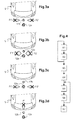
figures 3a to 3d are top views of the vehicle illustrating examples of impromptu objects that do not trigger opening of the movable panel, -
figure 4 is a diagram of an embodiment of a method for opening a movable panel of the motor vehicle using the detection device offigures 1 to 3d . - In these figures, identical elements have the same references.
- Referring to
figure 1 , the invention relates to anopening control device 1 for a motor vehicle V. - The
opening control device 1 comprises: - at least one
optical detector 3 for detecting the approach of a person U in the vicinity of the vehicle V in order to activate opening command means of an opening control device for opening amovable panel 7 of the vehicle V; - authentication means (not illustrated) for verifying that the detected person U near the vehicle V is an authorized person for unlocking the vehicle V and for activating opening command means when an authorized person is identified;
- opening command means of the movable panel.
- The
optical detector 3 is mounted on the vehicle V. According to one embodiment, theoptical detector 3 is arranged on the vehiclemovable panel 7 to be opened, such as a side door or atailgate 7. - The
optical detector 3 comprises a transmitter and a receiver. The transmitter is able to project a detection beam. Advantageously, the projected detection beam is of wavelength of invisible spectrum for human, infrared beam in a preferred embodiment. Thus, theoptical detector 3 is advantageously aninfrared detector 3. - The transmitter is further configured to project long reach detection beams.
- The authentication means (not illustrated) for verifying that the detected person U, also named user U, near the vehicle V is an authorized person for unlocking the vehicle V may comprise an antenna able to communicate with an identifier such as a transponder carried by the user U, for example in the key, or disposed adjacent to the user U. The transponder is adapted to receive a signal sent by the antenna.
- The antenna is connected to identifying means on-board. This identifying means may determine if the person holding or adjacent to the transponder is an authorized person.
- The opening command means comprise light projection means 9 of at least a light beam.
- The light projection means 9 are mounted on the vehicle V, for example on the
movable panel 7 such as a side door or the tailgate 7 (figure 1 ). - The light projection means 9 may comprise one or more diodes to achieve the one or more light beams. The light beam may be of any color.
- The light beam is projected on the ground on which the vehicle V stands thus forming a
light pattern 11 on the ground as shown infigure 1 . Thelight pattern 11 may be of any shape, including a luminous round, an arrow indicating a direction, a cross. The shape may be an opened shape such as a "U-shape" or a closed shape for instance a round or an oval shape. - According to the invention, the light projection means project at least two
light spots light spots light pattern 11 or may form together alight pattern 11. - Of course, the
light spots light spots movable panel 7. - In the example shown in
figure 1 , afirst light spot 12a and a secondlight spot 12b forming twovirtual switches first light spot 12a and the secondlight spot 12b, so that bothvirtual switches - In the illustrated example of
figure 1 , the secondlight spot 12b is closer to the vehicle V than thefirst light spot 12a. The closestlight spot 12b from the vehicle V is here smallest than thefirst light spot 12a. - The at least two
light spots figure 1 . - Of course, other orientations are possible. As can be seen in
figure 2 , the projection means 9 may be arranged in order to project twolight spots light spots 12a' and 12b' forming an angle, meaning a non null angle, with regard to the longitudinal axis of the vehicle V. - In other words, the
opening control device 1 may comprise one projection means 9 and processing means for adapting the orientation of the projection means 9 depending on where an approaching person U is detected, for instance by theoptical detector 3. Alternatively, theopening control device 1 may comprise several projection means 9 arranged on the vehicle V with different orientation and processing means for selecting the projection means 9 to be activated depending on where an approaching person U is detected, for instance by theoptical detector 3. - The at least two
light spots light pattern 11 define respectively a detection angle α, α' of the movement of one human part such as a foot performing the gesture command. This detection angle α, α' is for example predefined. Alternatively, theopening control device 1 may comprise means for adapting the angle width. - According to an embodiment, the projection means 9 are configured to project the
first light spot light spot - Alternatively, the projection means 9 may be configured to first project only the
first light spot light spot first light spot first light spot light spot - Moreover, the projection means 9 may be configured to project the second
light spot - If the user U doesn't stop on the second
light spot light spot first light spot light spot first light spot - This embodiment offers an ergonomic aid for the user U because the user U is guided through the
successive light spots - The opening command means further comprise determination means for determining if there is an intention to open the
movable panel 7. The determination means are configured to determine whether a gesture command by placement or movement of one human part, such as one hand or foot, is made in accordance with a predetermined manner and if themovable panel 7 can be opened or not. - The predetermined manner is a triggering sequence. The user has to stop on the
first light spot light spot light spots light spot first light spot 12a. - So, the user U has to move in direction to the vehicle V.
- Referring to
figure 1 , a movement according to the arrow F in direction to the vehicle V during which the user U stops on the secondlight spot 12b only after having stopped on thefirst light spot 12a can be identified as a correct trigger sequence. - Thus the
opening control device 1 comprises means for identifying if the identified authorized person U performs a predefined triggering sequence by stopping in a predetermined order on thefirst light spot 12a and then on the second light spot. - Both
light spots - More precisely, a predefined time interval between the moment of stopping on the
first light spot 12a and the moment of stopping on the secondlight spot 12b must be respected. This time interval defines a minimum time limit and a maximum time limit, both time limits are non null. Thus the time elapsed or the time differential between the time when stopping on the secondlight spot 12b and the time when stopping on thefirst light spot 12a must be comprised in the predefined time interval, being higher than the minimum time limit and lower than the maximum time limit. If none or only one of those two conditions is true, the opening of themovable panel 7 cannot be triggered. - This advantageously avoids that an impromptu object such as a tree branch, or a ball or a small animal may activate the
movable panel 7 opening by interacting with thevirtual switches light pattern 11 on the ground. - For that purpose, the
opening control device 1 may further comprise means for measuring the time elapsed between the moment of stopping on thefirst light spot 12a and the moment of stopping on the secondlight spot 12b, and means for determining if the lapse of time between the moment of stopping on thefirst light spot 12a and the moment of stopping on the secondlight spot 12b is comprised in the predefined time interval. - Alternatively, in case the second
light spot 12b is projected when the user U stops on thefirst light spot 12a, the secondlight spot 12b is projected only for a predefined time interval, and the user U has to stop on the secondlight spot 12b during this predefined time interval. - Examples of wrong sequences that cannot trigger the opening of the
movable panel 7 are illustrated in a schematic way infigures 3a to 3d , such as stopping only on one light spot forming a virtual switch, or crossing both light spots at same time or stopping on the light spots in the wrong order, meaning first the secondlight spot 12b and then thefirst light spot 12a. - Taking for example
figures 3a and 3c , a small object moving according to an arrow F1' or F2' crossing only one of the twolight spots - In
figure 3a , a small object moving according to arrow F1' coming from the left relatively tofigure 3a , only crosses the secondlight spot 12b and never crosses thefirst light spot 12a. Thus, the movement of the impromptu object activating randomly the secondvirtual switch 12b but not the firstvirtual switch 12a cannot be identified as a correct trigger sequence. - It is similar when a small object moving according to arrow F2' coming from the right relatively to
figure 3a , only crosses the secondlight spot 12b and never crosses the first light spot 3a, thus, cannot be identified as a correct trigger sequence. - In
figure 3c , a small object moving according to arrow F1', respectively F2', coming from the left, respectively the right, relatively tofigure 3c , only crosses thefirst light spot 12a and never crosses the secondlight spot 12b. Thus, the movement of the impromptu object activating randomly the firstvirtual switch 12a but not the secondvirtual switch 12b cannot be identified as a correct trigger sequence. - Considering now a bigger object, moving indifferently according to arrow F1', or according to arrow F2', coming from the left, respectively from the right, relatively to
figure 3b , if this object crosses simultaneously both secondlight spot 12b andfirst light spot 12a, the movement activating simultaneously bothvirtual switches virtual switches - Referring to another example in
figure 3d , when an object moving according to arrow F' crosses first the secondlight spot 12b and then thefirst light spot 12a, it cannot be identified as a correct trigger sequence because the predefined order is not verified. - Referring back to
figures 1 and 2 , one or moreoptical sensors 13 may be configured to detect any variation from the light beam in order to detect if the user has stopped on thefirst light spot light spot - According to the embodiment of
figure 1 , theoptical sensors 13 are arranged on the movable panel to be opened, for instance on thetailgate 7. - The
optical detector 3, the light projection means 9 and theoptical sensors 13 may be arranged close relative to each other, for example on or near therear registration plate 15 as illustrated infigure 2 . - The
optical sensors 13 are intended to detect any variation in brightness due to interception of a light beam by an object or by a human part, such as foot or hand. - The
optical sensors 13 may be connected to the determination means which determine that the movement has or has not been done properly, meaning according to the predefined trigger sequence as explained above. The determination means may trigger the opening of themovable panel 7 when the movement has been done properly or not to trigger the opening of themovable panel 7 when the movement has not been done properly. - Referring now to
figure 4 , a method for opening a movable panel of the motor vehicle is described. - As shown in
figure 4 , the method for opening amovable panel 7 of a motor vehicle comprises the following steps S1 to S7. - At step S1, detecting the approach of a person near the vehicle V by one or more
optical detectors 3. For that, at least a portion of the body of a person U may be detected. - Once step S1 is performed and validated, meaning a person is detected, step S2 can begin.
- At step S2, authenticating the detected person U as authorized to unlock the vehicle V through authentication means. That is a step to verify and validate the identity of a person to be entitled to access to the vehicle.
- If an authorized person is identified, the method can perform step S3.
- If the approaching person is not identified as an authorized person, step S1 starts again.
- At step S3, activating opening command means for opening a
movable panel 7 of the motor vehicle, if an authorized person U is identified. Step S3 is only performed when steps S1 and S2 are validated. - As an example, depending on where an approaching person U is detected for instance by the optical detector and/or by the authentication means, the orientation of the projection means 9 of the light spots may be adapted.
- Alternatively, depending on where an approaching person U is detected for instance by the optical detector and/or by the authentication means, the method may comprise a sub-step of selecting at least one projection means 9 to be activated among several projection means 9 arranged on the motor vehicle V with different orientation relative to each other.
- According to a first embodiment, at step S4, projecting at least one
first light spot figure 1 , and projecting at least one secondlight spot - Both
light spots - Both
light spots - These
light spots movable panel 7. - Alternatively at step S4, only the
first light spot - At step S5, performing a predefined gesture command for opening a vehicle
movable panel 7. That means, the user U has to perform a predefined trigger sequence. - According to the described example in
figure 1 , the user U may place one human part, such as one hand or one foot, in the light beam, in order to obscure or hide first the first virtual switch formed by thefirst light spot light spot - The
first light spot light spot first light spot light spot movable panel 7. - Alternatively at step S5, the user U may place one human part, such as one hand or one foot, in the light beam, in order to obscure or hide first the first virtual switch formed by the
first light spot light spot first light spot light spot light spot - At step S6, identifying an authorized gesture command. That means identifying if the placement or movement of the foot or hand or any other human part, is made according or not to the predefined triggering sequence.
- For that purpose, the method comprises according to the first embodiment, a step of measuring the time elapsed between the moment of stopping on the
first light spot light spot - Alternatively, the method comprises a step S6 for determining if the user U has stopped on the second
light spot - Step S6 allows the
opening control device 1 to identify if there is an intention to open the vehiclemovable panel 7. - If the gesture of the foot or hand for example is not performed according to the predefined trigger sequence, a signal may be sent to indicate to perform again the triggering sequence at step S5. In case it is necessary to repeat step S5, the user U must move his foot or hand for example to reposition it correctly according to the predefined trigger sequence. The signal to reposition the human part such as hand or foot, may be a visual signal for example a flashing of the light beam, a change in color of the light beam, and/or a signal tone.
- If the authorized person U performs the predefined triggering sequence, a signal may be sent for authorizing the opening of the
movable panel 7 and the opening command means can open themovable panel 7. The light spots projections are stopped. - At step S7, opening the vehicle
movable panel 7 if the predefined triggering sequence has been performed. As a consequence, the opening of the vehiclemovable panel 7 is achieved only if the gesture of the user U is made according to a precise trigger sequence. - Then, the
movable panel 7 is opened, the user U may get in the vehicle or put something in the trunk. - Thus, virtual switches are shown only when an authorized user is identified. Two first conditions are required before projecting virtual switches for triggering the opening of the movable panel. This avoids a permanent projection of triggering area, here the at least two
light spots - Then, the projection of at least two
virtual switches - Through such a method and corresponding opening control device, the opening of the
movable panel 7 of the motor vehicle V is reliable and efficient while requiring low electrical supplying.
Claims (13)
- Method for opening a movable panel of a motor vehicle, comprising the following steps of:- detecting the approach of a person (U) in the vicinity of the vehicle (V) by a detection device (3),- identifying if the detected person (U) is authorized to unlock the vehicle (V) through authentication means,- determining if there is an intention to open the movable panel (7), and- authorizing the opening of the movable panel (7) when an authorized person (U) with an intention to open the movable panel is detected,
characterized in that the step of determining if there is an intention to open the movable panel (7), comprises the sub-steps of:- projecting at least a first light spot (12a; 12a') on the ground on which the motor vehicle (V) stands,- projecting at least a second light spot (12b; 12b') on the ground on which the motor vehicle (V) stands with a predefined distance from the first light spot (12a; 12a'),- identifying if the identified authorized person (U) performs a predefined triggering sequence:by stopping in a predetermined order on the first light spot (12a; 12a') and then on the second light spot (12b; 12b') andwith a predefined time interval between the step of stopping on the first light spot (12a; 12a') and the step of stopping on the second light spot (12b, 12b'). - Method as set forth in claim 1, wherein the first light spot (12a; 12a') and the second light spot (12b; 12b') are projected on the ground together simultaneously when an authorized person (U) is identified.
- Method as set forth in claim 2, comprising a step of measuring the time elapsed between the step of stopping on the first light spot (12a; 12a') and the step of stopping on the second light spot (12b, 12b'), and a step of comparing the measured elapsed time to the predefined time interval.
- Method as set forth in claim 1, wherein:- the first light spot (12a, 12a') is projected on the ground when an authorized person (U) is identified,- the second light spot (12b, 12b') is projected on the ground when the authorized person (U) has stopped on the first light spot (12a, 12a') and for the predefined time interval.
- Method as set forth in any one of the preceding claims, wherein the second light spot (12b; 12b') is projected closer to the vehicle (V) than the first light spot (12a; 12a').
- Method as set forth in any one of claims 1 to 5, wherein said at least two light spots (12a, 12b) are aligned with regard to the longitudinal axis of the motor vehicle (V).
- Method as set forth in any one of claims 1 to 5, wherein said at least two light spots (12a, 12b) are aligned relative to each other and form an angle with regard to the longitudinal axis of the motor vehicle (V).
- Method as set forth in any one of the preceding claims, comprising a step of sending a warning signal to indicate to perform again the triggering sequence, if the predefined triggering sequence is incorrect.
- Method as set forth in one of the preceding claims, wherein the step of detecting the approach of a person in the vicinity of the vehicle (V) is performed by one or more optical detectors (3), for example infrared detectors (3).
- Opening control device (1) comprising at least one means for:- detecting the approach of a person (U) in the vicinity of the vehicle (V),- identifying if the detected person (U) is authorized to unlock the vehicle (V) through authentication means,- determining if there is an intention to open the movable panel (7), and- authorizing the opening of the movable panel (7) when an authorized person (U) with an intention to open the movable panel is detected,
characterized in that the means for determining if there is an intention to open the movable panel (7), comprises:- projection means (9) for projecting on the ground on which the motor vehicle (V) stands at least a first light spot (12a; 12a') and at least a second light spot (12b, 12b'),- means for identifying if the identified authorized person (U) performs a predefined triggering sequence by stopping in a predetermined order on the first light spot (12a; 12a') and then on the second light spot (12b; 12b') with a predefined time interval between the moment of stopping on the first light spot (12a; 12a') and the moment of stopping on the second light spot (12b, 12b'). - Opening control device as set forth in claim 10, comprising a detection device (3) for detecting the approach of a person (U) in the vicinity of the vehicle (V), comprising one or more optical detectors (3), for example infrared detectors (3).
- Opening control device as set forth in claim 10 or 11, comprising processing means for adapting the orientation of the projection means (9) depending on where an approaching person (U) is detected.
- Opening control device as set forth in claim 10 or 1l, comprising several projection means (9) arranged on the motor vehicle (V) with different orientation relative to each other, and comprising processing means for selecting at least one projection means (9) to be activated depending on where an approaching person (U) is detected.
Priority Applications (5)
| Application Number | Priority Date | Filing Date | Title |
|---|---|---|---|
| EP13188134.4A EP2860704B1 (en) | 2013-10-10 | 2013-10-10 | Method for opening a movable panel of the motor vehicle and corresponding opening control device |
| JP2016521747A JP6528030B2 (en) | 2013-10-10 | 2014-10-08 | Method for opening a movable panel of a motor vehicle, and related opening control device |
| CN201480055591.0A CN105636838A (en) | 2013-10-10 | 2014-10-08 | Method for opening a movable panel of the motor vehicle and corresponding opening control device |
| US14/911,481 US9739082B2 (en) | 2013-10-10 | 2014-10-08 | Method for opening a movable panel of the motor vehicle and corresponding opening control device |
| PCT/EP2014/071577 WO2015052259A1 (en) | 2013-10-10 | 2014-10-08 | Method for opening a movable panel of the motor vehicle and corresponding opening control device |
Applications Claiming Priority (1)
| Application Number | Priority Date | Filing Date | Title |
|---|---|---|---|
| EP13188134.4A EP2860704B1 (en) | 2013-10-10 | 2013-10-10 | Method for opening a movable panel of the motor vehicle and corresponding opening control device |
Publications (2)
| Publication Number | Publication Date |
|---|---|
| EP2860704A1 true EP2860704A1 (en) | 2015-04-15 |
| EP2860704B1 EP2860704B1 (en) | 2016-04-27 |
Family
ID=49354484
Family Applications (1)
| Application Number | Title | Priority Date | Filing Date |
|---|---|---|---|
| EP13188134.4A Active EP2860704B1 (en) | 2013-10-10 | 2013-10-10 | Method for opening a movable panel of the motor vehicle and corresponding opening control device |
Country Status (5)
| Country | Link |
|---|---|
| US (1) | US9739082B2 (en) |
| EP (1) | EP2860704B1 (en) |
| JP (1) | JP6528030B2 (en) |
| CN (1) | CN105636838A (en) |
| WO (1) | WO2015052259A1 (en) |
Cited By (9)
| Publication number | Priority date | Publication date | Assignee | Title |
|---|---|---|---|---|
| WO2015139932A1 (en) * | 2014-03-17 | 2015-09-24 | Volkswagen Aktiengesellschaft | Method and device for actuating a closing element for a vehicle |
| EP2952661A1 (en) * | 2014-06-06 | 2015-12-09 | MAN Truck & Bus AG | Method and device for the contactless opening an access and/or exit from on a vehicle for passenger transport and vehicle for passenger transport equipped with such a device |
| DE102016100069A1 (en) * | 2016-01-04 | 2017-07-06 | Volkswagen Ag | Method and device for external actuation of an actuator of a vehicle |
| GB2547475A (en) * | 2016-02-22 | 2017-08-23 | Jaguar Land Rover Ltd | Providing gesture-initiated operation feedback |
| JP2018531332A (en) * | 2015-11-02 | 2018-10-25 | アイシン テクニカル センター オブ アメリカ インコーポレイテッドAisin Technical Center Of America,Inc. | Apparatus and method for visually communicating with a vehicle |
| CN109074691A (en) * | 2016-04-11 | 2018-12-21 | 开利公司 | Personal user is captured when interacting with multiple access control apparatus to be intended to |
| CN109074690A (en) * | 2016-04-11 | 2018-12-21 | 开利公司 | Communication user is captured when interacting with multiple access control apparatus to be intended to |
| CN109878451A (en) * | 2019-03-11 | 2019-06-14 | 汉腾汽车有限公司 | A kind of control system of automobile intelligent unlock |
| WO2020260378A1 (en) * | 2019-06-26 | 2020-12-30 | Brose Fahrzeugteile Se & Co. Kommmanditgesellschaft, Bambgerg | Adjustment system and method for adjusting an adjustable vehicle part in a manner actuated by external force with the aid of a detection device |
Families Citing this family (21)
| Publication number | Priority date | Publication date | Assignee | Title |
|---|---|---|---|---|
| DE102011121775B3 (en) | 2011-12-21 | 2013-01-31 | Brose Fahrzeugteile Gmbh & Co. Kg, Hallstadt | Control system for controlling e.g. motorized side door of motor car, has distance sensors with dummy portions such that sensors comprise no sensitivity or smaller sensitivity compared to region of each sensor adjacent to dummy portions |
| JP6211506B2 (en) * | 2014-12-03 | 2017-10-11 | アイシン精機株式会社 | Open / close detection device for vehicle opening / closing body |
| DE102015112589A1 (en) | 2015-07-31 | 2017-02-02 | Brose Fahrzeugteile Gmbh & Co. Kommanditgesellschaft, Bamberg | Control system for a motor-adjustable loading space device of a motor vehicle |
| US11225822B2 (en) * | 2015-09-03 | 2022-01-18 | Faraday&Future Inc. | System and method for opening and closing vehicle door |
| US11313159B2 (en) | 2015-09-12 | 2022-04-26 | Adac Plastics, Inc. | Gesture access system for a motor vehicle |
| US10415276B2 (en) | 2015-09-12 | 2019-09-17 | Adac Plastics, Inc. | Gesture access and object impact avoidance system for a motor vehicle |
| DE102015224108A1 (en) * | 2015-12-02 | 2017-06-08 | Bayerische Motoren Werke Aktiengesellschaft | Control device and control method for a vehicle with automatically opening and / or automatically closing flap |
| DE102016108702A1 (en) * | 2016-05-11 | 2017-11-16 | Brose Fahrzeugteile Gmbh & Co. Kg, Bamberg | Method for controlling a motor-driven closure element arrangement of a motor vehicle |
| JP6927988B2 (en) * | 2016-10-04 | 2021-09-01 | 株式会社ユーシン | Door switchgear |
| JP6702151B2 (en) * | 2016-11-16 | 2020-05-27 | トヨタ車体株式会社 | Vehicle control device |
| DE102017204078B4 (en) * | 2017-03-13 | 2020-04-02 | Continental Automotive Gmbh | Method for controlling a closure element of a vehicle |
| US10577851B2 (en) * | 2017-06-15 | 2020-03-03 | GM Global Technology Operations LLC | Automatic closure system with active distance control |
| JP6817581B2 (en) * | 2017-08-31 | 2021-01-20 | パナソニックIpマネジメント株式会社 | Electric lock control system, electric lock system, control method of electric lock control system, and program |
| US10829034B2 (en) * | 2018-03-29 | 2020-11-10 | Aisin Seiki Kabushiki Kaisha | Vehicle control device |
| US20190299848A1 (en) * | 2018-03-29 | 2019-10-03 | Aisin Seiki Kabushiki Kaisha | User guidance device |
| JP2019173541A (en) * | 2018-03-29 | 2019-10-10 | アイシン精機株式会社 | Vehicle control device |
| US10794107B2 (en) * | 2018-04-10 | 2020-10-06 | Ford Global Technologies, Llc | Vehicle door entry system and method |
| DE102018207663B3 (en) * | 2018-05-16 | 2019-10-10 | Volkswagen Aktiengesellschaft | Method for detecting a user input and vehicle |
| JP7018412B2 (en) * | 2018-06-15 | 2022-02-10 | スタビラス ゲ―エムベーハー | How to adjust the force applied to operate the lid |
| CN110525377A (en) * | 2019-08-26 | 2019-12-03 | 北京一数科技有限公司 | A kind of automobile trunk door control method and device |
| US11702880B2 (en) | 2020-08-27 | 2023-07-18 | Extang Corporation | Capacitive touch vehicle accessory |
Citations (3)
| Publication number | Priority date | Publication date | Assignee | Title |
|---|---|---|---|---|
| US20080296926A1 (en) * | 2007-06-01 | 2008-12-04 | Gm Global Technology Operations, Inc. | Arms full vehicle closure activation apparatus and method |
| DE102008021989A1 (en) * | 2008-05-02 | 2008-12-18 | Daimler Ag | Device for locking and unlocking unit of electronic conditional access system secured vehicle door for vehicle, has unlocking sensor that is formed as project control panel for unlocking vehicle door |
| FR2979873A1 (en) * | 2011-09-12 | 2013-03-15 | Valeo Securite Habitacle | METHOD FOR OPENING AN OPENING OF A MOTOR VEHICLE |
Family Cites Families (11)
| Publication number | Priority date | Publication date | Assignee | Title |
|---|---|---|---|---|
| US5318143A (en) * | 1992-06-22 | 1994-06-07 | The Texas A & M University System | Method and apparatus for lane sensing for automatic vehicle steering |
| DE19704466A1 (en) * | 1997-02-06 | 1998-08-13 | Bosch Gmbh Robert | Device for regulating the headlight range of vehicle headlights |
| DE102004041709C5 (en) * | 2004-08-28 | 2009-11-12 | Bayerische Motoren Werke Aktiengesellschaft | Vehicle with automatic opening flap |
| US20060093203A1 (en) * | 2004-11-04 | 2006-05-04 | Rockwell Automation Technologies, Inc. | Attribute threshold evaluation scheme |
| DE102010018164B4 (en) * | 2010-02-01 | 2023-03-02 | Huf Hülsbeck & Fürst Gmbh & Co. Kg | Virtual switch and method of operating one |
| DE102010049400A1 (en) * | 2010-10-26 | 2012-04-26 | Brose Fahrzeugteile Gmbh & Co. Kommanditgesellschaft, Hallstadt | Sensor unit for contactless actuation of a vehicle door |
| US8706350B2 (en) * | 2010-12-17 | 2014-04-22 | GM Global Technology Operations LLC | Secondary sensing for intelligent passive entry passive start polling |
| JP5382050B2 (en) * | 2011-04-06 | 2014-01-08 | アイシン精機株式会社 | Opening and closing body actuator for vehicle |
| KR101316873B1 (en) * | 2012-07-04 | 2013-10-08 | 현대자동차주식회사 | System and method for operating gate |
| JP6112292B2 (en) * | 2012-12-25 | 2017-04-12 | 三菱自動車工業株式会社 | Sliding door opening and closing device |
| US8823552B1 (en) * | 2013-04-04 | 2014-09-02 | GM Global Technology Operations LLC | Vehicle with apparatus for generating and displaying a predefined light pattern |
-
2013
- 2013-10-10 EP EP13188134.4A patent/EP2860704B1/en active Active
-
2014
- 2014-10-08 CN CN201480055591.0A patent/CN105636838A/en active Pending
- 2014-10-08 WO PCT/EP2014/071577 patent/WO2015052259A1/en active Application Filing
- 2014-10-08 US US14/911,481 patent/US9739082B2/en active Active
- 2014-10-08 JP JP2016521747A patent/JP6528030B2/en active Active
Patent Citations (3)
| Publication number | Priority date | Publication date | Assignee | Title |
|---|---|---|---|---|
| US20080296926A1 (en) * | 2007-06-01 | 2008-12-04 | Gm Global Technology Operations, Inc. | Arms full vehicle closure activation apparatus and method |
| DE102008021989A1 (en) * | 2008-05-02 | 2008-12-18 | Daimler Ag | Device for locking and unlocking unit of electronic conditional access system secured vehicle door for vehicle, has unlocking sensor that is formed as project control panel for unlocking vehicle door |
| FR2979873A1 (en) * | 2011-09-12 | 2013-03-15 | Valeo Securite Habitacle | METHOD FOR OPENING AN OPENING OF A MOTOR VEHICLE |
Cited By (13)
| Publication number | Priority date | Publication date | Assignee | Title |
|---|---|---|---|---|
| WO2015139932A1 (en) * | 2014-03-17 | 2015-09-24 | Volkswagen Aktiengesellschaft | Method and device for actuating a closing element for a vehicle |
| US9956940B2 (en) | 2014-03-17 | 2018-05-01 | Volkswagen Ag | Method and device for actuating a closing element for a vehicle |
| EP2952661A1 (en) * | 2014-06-06 | 2015-12-09 | MAN Truck & Bus AG | Method and device for the contactless opening an access and/or exit from on a vehicle for passenger transport and vehicle for passenger transport equipped with such a device |
| JP2018531332A (en) * | 2015-11-02 | 2018-10-25 | アイシン テクニカル センター オブ アメリカ インコーポレイテッドAisin Technical Center Of America,Inc. | Apparatus and method for visually communicating with a vehicle |
| DE102016100069A1 (en) * | 2016-01-04 | 2017-07-06 | Volkswagen Ag | Method and device for external actuation of an actuator of a vehicle |
| US10071706B2 (en) | 2016-01-04 | 2018-09-11 | Volkswagen Aktiengesellschaft | Method and apparatus for external operation of an actuator of a vehicle |
| GB2547475A (en) * | 2016-02-22 | 2017-08-23 | Jaguar Land Rover Ltd | Providing gesture-initiated operation feedback |
| GB2547475B (en) * | 2016-02-22 | 2019-05-01 | Jaguar Land Rover Ltd | Method and system of providing gesture-initiated operation feedback |
| CN109074691A (en) * | 2016-04-11 | 2018-12-21 | 开利公司 | Personal user is captured when interacting with multiple access control apparatus to be intended to |
| CN109074690A (en) * | 2016-04-11 | 2018-12-21 | 开利公司 | Communication user is captured when interacting with multiple access control apparatus to be intended to |
| CN109074691B (en) * | 2016-04-11 | 2022-07-29 | 开利公司 | Capturing individual user intent while interacting with multiple access control devices |
| CN109878451A (en) * | 2019-03-11 | 2019-06-14 | 汉腾汽车有限公司 | A kind of control system of automobile intelligent unlock |
| WO2020260378A1 (en) * | 2019-06-26 | 2020-12-30 | Brose Fahrzeugteile Se & Co. Kommmanditgesellschaft, Bambgerg | Adjustment system and method for adjusting an adjustable vehicle part in a manner actuated by external force with the aid of a detection device |
Also Published As
| Publication number | Publication date |
|---|---|
| EP2860704B1 (en) | 2016-04-27 |
| US9739082B2 (en) | 2017-08-22 |
| CN105636838A (en) | 2016-06-01 |
| JP6528030B2 (en) | 2019-06-12 |
| JP2016532794A (en) | 2016-10-20 |
| US20160186480A1 (en) | 2016-06-30 |
| WO2015052259A1 (en) | 2015-04-16 |
Similar Documents
| Publication | Publication Date | Title |
|---|---|---|
| EP2860704B1 (en) | Method for opening a movable panel of the motor vehicle and corresponding opening control device | |
| US9394737B2 (en) | Method for opening a movable panel of a motor vehicle | |
| US9812017B2 (en) | Detection device for a motor vehicle and associated methods for detecting an obstacle and for opening a movable panel of the motor vehicle | |
| US10151134B2 (en) | Method for opening a movable panel of the motor vehicle and corresponding opening control device | |
| US8935052B2 (en) | Method for controlling a door of a vehicle | |
| US11518341B2 (en) | Method for controlling a locking element of a vehicle | |
| US10005428B2 (en) | Assembly module | |
| US20170113652A1 (en) | Door opening and closing device | |
| CN104169978A (en) | Portable authentication means and vehicle security system for a motor vehicle | |
| CN105980221A (en) | Assembly Module For A Motor Vehicle, Comprising An Optical Sensor System And An Emergency Actuation Means | |
| US20200094777A1 (en) | Access and/or starting device for a vehicle | |
| CN105960358A (en) | Method of preparing an operating signal | |
| WO2016063310A1 (en) | Locking and unlocking control unit, locking and unlocking system, and locking and unlocking device control method | |
| JP7010686B2 (en) | Vehicle door control device | |
| KR20080098116A (en) | Non-contact type electron door lock apparatus for glass door | |
| CN107635836B (en) | Access system and driving authorization system with improved security against relay attacks on the response interface |
Legal Events
| Date | Code | Title | Description |
|---|---|---|---|
| PUAI | Public reference made under article 153(3) epc to a published international application that has entered the european phase |
Free format text: ORIGINAL CODE: 0009012 |
|
| 17P | Request for examination filed |
Effective date: 20131010 |
|
| AK | Designated contracting states |
Kind code of ref document: A1 Designated state(s): AL AT BE BG CH CY CZ DE DK EE ES FI FR GB GR HR HU IE IS IT LI LT LU LV MC MK MT NL NO PL PT RO RS SE SI SK SM TR |
|
| AX | Request for extension of the european patent |
Extension state: BA ME |
|
| GRAP | Despatch of communication of intention to grant a patent |
Free format text: ORIGINAL CODE: EPIDOSNIGR1 |
|
| R17P | Request for examination filed (corrected) |
Effective date: 20151012 |
|
| RBV | Designated contracting states (corrected) |
Designated state(s): AL AT BE BG CH CY CZ DE DK EE ES FI FR GB GR HR HU IE IS IT LI LT LU LV MC MK MT NL NO PL PT RO RS SE SI SK SM TR |
|
| INTG | Intention to grant announced |
Effective date: 20151106 |
|
| RAP1 | Party data changed (applicant data changed or rights of an application transferred) |
Owner name: U-SHIN FRANCE SAS |
|
| GRAS | Grant fee paid |
Free format text: ORIGINAL CODE: EPIDOSNIGR3 |
|
| GRAA | (expected) grant |
Free format text: ORIGINAL CODE: 0009210 |
|
| AK | Designated contracting states |
Kind code of ref document: B1 Designated state(s): AL AT BE BG CH CY CZ DE DK EE ES FI FR GB GR HR HU IE IS IT LI LT LU LV MC MK MT NL NO PL PT RO RS SE SI SK SM TR |
|
| REG | Reference to a national code |
Ref country code: GB Ref legal event code: FG4D |
|
| REG | Reference to a national code |
Ref country code: CH Ref legal event code: EP |
|
| REG | Reference to a national code |
Ref country code: AT Ref legal event code: REF Ref document number: 795546 Country of ref document: AT Kind code of ref document: T Effective date: 20160515 |
|
| REG | Reference to a national code |
Ref country code: IE Ref legal event code: FG4D |
|
| REG | Reference to a national code |
Ref country code: DE Ref legal event code: R096 Ref document number: 602013006925 Country of ref document: DE |
|
| REG | Reference to a national code |
Ref country code: LT Ref legal event code: MG4D |
|
| REG | Reference to a national code |
Ref country code: NL Ref legal event code: MP Effective date: 20160427 |
|
| REG | Reference to a national code |
Ref country code: AT Ref legal event code: MK05 Ref document number: 795546 Country of ref document: AT Kind code of ref document: T Effective date: 20160427 |
|
| PG25 | Lapsed in a contracting state [announced via postgrant information from national office to epo] |
Ref country code: NL Free format text: LAPSE BECAUSE OF FAILURE TO SUBMIT A TRANSLATION OF THE DESCRIPTION OR TO PAY THE FEE WITHIN THE PRESCRIBED TIME-LIMIT Effective date: 20160427 |
|
| PG25 | Lapsed in a contracting state [announced via postgrant information from national office to epo] |
Ref country code: PL Free format text: LAPSE BECAUSE OF FAILURE TO SUBMIT A TRANSLATION OF THE DESCRIPTION OR TO PAY THE FEE WITHIN THE PRESCRIBED TIME-LIMIT Effective date: 20160427 Ref country code: LT Free format text: LAPSE BECAUSE OF FAILURE TO SUBMIT A TRANSLATION OF THE DESCRIPTION OR TO PAY THE FEE WITHIN THE PRESCRIBED TIME-LIMIT Effective date: 20160427 Ref country code: NO Free format text: LAPSE BECAUSE OF FAILURE TO SUBMIT A TRANSLATION OF THE DESCRIPTION OR TO PAY THE FEE WITHIN THE PRESCRIBED TIME-LIMIT Effective date: 20160727 Ref country code: FI Free format text: LAPSE BECAUSE OF FAILURE TO SUBMIT A TRANSLATION OF THE DESCRIPTION OR TO PAY THE FEE WITHIN THE PRESCRIBED TIME-LIMIT Effective date: 20160427 |
|
| PG25 | Lapsed in a contracting state [announced via postgrant information from national office to epo] |
Ref country code: AT Free format text: LAPSE BECAUSE OF FAILURE TO SUBMIT A TRANSLATION OF THE DESCRIPTION OR TO PAY THE FEE WITHIN THE PRESCRIBED TIME-LIMIT Effective date: 20160427 Ref country code: ES Free format text: LAPSE BECAUSE OF FAILURE TO SUBMIT A TRANSLATION OF THE DESCRIPTION OR TO PAY THE FEE WITHIN THE PRESCRIBED TIME-LIMIT Effective date: 20160427 Ref country code: LV Free format text: LAPSE BECAUSE OF FAILURE TO SUBMIT A TRANSLATION OF THE DESCRIPTION OR TO PAY THE FEE WITHIN THE PRESCRIBED TIME-LIMIT Effective date: 20160427 Ref country code: HR Free format text: LAPSE BECAUSE OF FAILURE TO SUBMIT A TRANSLATION OF THE DESCRIPTION OR TO PAY THE FEE WITHIN THE PRESCRIBED TIME-LIMIT Effective date: 20160427 Ref country code: SE Free format text: LAPSE BECAUSE OF FAILURE TO SUBMIT A TRANSLATION OF THE DESCRIPTION OR TO PAY THE FEE WITHIN THE PRESCRIBED TIME-LIMIT Effective date: 20160427 Ref country code: PT Free format text: LAPSE BECAUSE OF FAILURE TO SUBMIT A TRANSLATION OF THE DESCRIPTION OR TO PAY THE FEE WITHIN THE PRESCRIBED TIME-LIMIT Effective date: 20160829 Ref country code: GR Free format text: LAPSE BECAUSE OF FAILURE TO SUBMIT A TRANSLATION OF THE DESCRIPTION OR TO PAY THE FEE WITHIN THE PRESCRIBED TIME-LIMIT Effective date: 20160728 Ref country code: RS Free format text: LAPSE BECAUSE OF FAILURE TO SUBMIT A TRANSLATION OF THE DESCRIPTION OR TO PAY THE FEE WITHIN THE PRESCRIBED TIME-LIMIT Effective date: 20160427 |
|
| PG25 | Lapsed in a contracting state [announced via postgrant information from national office to epo] |
Ref country code: IT Free format text: LAPSE BECAUSE OF FAILURE TO SUBMIT A TRANSLATION OF THE DESCRIPTION OR TO PAY THE FEE WITHIN THE PRESCRIBED TIME-LIMIT Effective date: 20160427 Ref country code: BE Free format text: LAPSE BECAUSE OF FAILURE TO SUBMIT A TRANSLATION OF THE DESCRIPTION OR TO PAY THE FEE WITHIN THE PRESCRIBED TIME-LIMIT Effective date: 20160427 |
|
| REG | Reference to a national code |
Ref country code: DE Ref legal event code: R097 Ref document number: 602013006925 Country of ref document: DE |
|
| PG25 | Lapsed in a contracting state [announced via postgrant information from national office to epo] |
Ref country code: RO Free format text: LAPSE BECAUSE OF FAILURE TO SUBMIT A TRANSLATION OF THE DESCRIPTION OR TO PAY THE FEE WITHIN THE PRESCRIBED TIME-LIMIT Effective date: 20160427 Ref country code: SK Free format text: LAPSE BECAUSE OF FAILURE TO SUBMIT A TRANSLATION OF THE DESCRIPTION OR TO PAY THE FEE WITHIN THE PRESCRIBED TIME-LIMIT Effective date: 20160427 Ref country code: EE Free format text: LAPSE BECAUSE OF FAILURE TO SUBMIT A TRANSLATION OF THE DESCRIPTION OR TO PAY THE FEE WITHIN THE PRESCRIBED TIME-LIMIT Effective date: 20160427 Ref country code: CZ Free format text: LAPSE BECAUSE OF FAILURE TO SUBMIT A TRANSLATION OF THE DESCRIPTION OR TO PAY THE FEE WITHIN THE PRESCRIBED TIME-LIMIT Effective date: 20160427 Ref country code: DK Free format text: LAPSE BECAUSE OF FAILURE TO SUBMIT A TRANSLATION OF THE DESCRIPTION OR TO PAY THE FEE WITHIN THE PRESCRIBED TIME-LIMIT Effective date: 20160427 |
|
| PG25 | Lapsed in a contracting state [announced via postgrant information from national office to epo] |
Ref country code: SM Free format text: LAPSE BECAUSE OF FAILURE TO SUBMIT A TRANSLATION OF THE DESCRIPTION OR TO PAY THE FEE WITHIN THE PRESCRIBED TIME-LIMIT Effective date: 20160427 |
|
| PLBE | No opposition filed within time limit |
Free format text: ORIGINAL CODE: 0009261 |
|
| PLAA | Information modified related to event that no opposition was filed |
Free format text: ORIGINAL CODE: 0009299DELT |
|
| PLBE | No opposition filed within time limit |
Free format text: ORIGINAL CODE: 0009261 |
|
| STAA | Information on the status of an ep patent application or granted ep patent |
Free format text: STATUS: NO OPPOSITION FILED WITHIN TIME LIMIT |
|
| 26N | No opposition filed |
Effective date: 20170130 |
|
| R26N | No opposition filed (corrected) |
Effective date: 20170130 |
|
| RIN2 | Information on inventor provided after grant (corrected) |
Inventor name: ETTE, BERND Inventor name: KRAUSS, DIETMAR Inventor name: MOLOCEA, DRAGOS |
|
| PG25 | Lapsed in a contracting state [announced via postgrant information from national office to epo] |
Ref country code: SI Free format text: LAPSE BECAUSE OF FAILURE TO SUBMIT A TRANSLATION OF THE DESCRIPTION OR TO PAY THE FEE WITHIN THE PRESCRIBED TIME-LIMIT Effective date: 20160427 |
|
| REG | Reference to a national code |
Ref country code: CH Ref legal event code: PL |
|
| REG | Reference to a national code |
Ref country code: IE Ref legal event code: MM4A |
|
| REG | Reference to a national code |
Ref country code: FR Ref legal event code: ST Effective date: 20170630 |
|
| PG25 | Lapsed in a contracting state [announced via postgrant information from national office to epo] |
Ref country code: CH Free format text: LAPSE BECAUSE OF NON-PAYMENT OF DUE FEES Effective date: 20161031 Ref country code: FR Free format text: LAPSE BECAUSE OF NON-PAYMENT OF DUE FEES Effective date: 20161102 Ref country code: LI Free format text: LAPSE BECAUSE OF NON-PAYMENT OF DUE FEES Effective date: 20161031 |
|
| PG25 | Lapsed in a contracting state [announced via postgrant information from national office to epo] |
Ref country code: LU Free format text: LAPSE BECAUSE OF NON-PAYMENT OF DUE FEES Effective date: 20161010 |
|
| PG25 | Lapsed in a contracting state [announced via postgrant information from national office to epo] |
Ref country code: IE Free format text: LAPSE BECAUSE OF NON-PAYMENT OF DUE FEES Effective date: 20161010 |
|
| REG | Reference to a national code |
Ref country code: GB Ref legal event code: 732E Free format text: REGISTERED BETWEEN 20171123 AND 20171129 |
|
| REG | Reference to a national code |
Ref country code: DE Ref legal event code: R081 Ref document number: 602013006925 Country of ref document: DE Owner name: VOLKSWAGEN AKTIENGESELLSCHAFT, DE Free format text: FORMER OWNER: U-SHIN FRANCE SAS, CRETEIL, FR Ref country code: DE Ref legal event code: R081 Ref document number: 602013006925 Country of ref document: DE Owner name: U-SHIN FRANCE SAS, FR Free format text: FORMER OWNER: U-SHIN FRANCE SAS, CRETEIL, FR |
|
| PG25 | Lapsed in a contracting state [announced via postgrant information from national office to epo] |
Ref country code: HU Free format text: LAPSE BECAUSE OF FAILURE TO SUBMIT A TRANSLATION OF THE DESCRIPTION OR TO PAY THE FEE WITHIN THE PRESCRIBED TIME-LIMIT; INVALID AB INITIO Effective date: 20131010 |
|
| PG25 | Lapsed in a contracting state [announced via postgrant information from national office to epo] |
Ref country code: MC Free format text: LAPSE BECAUSE OF FAILURE TO SUBMIT A TRANSLATION OF THE DESCRIPTION OR TO PAY THE FEE WITHIN THE PRESCRIBED TIME-LIMIT Effective date: 20160427 Ref country code: MK Free format text: LAPSE BECAUSE OF FAILURE TO SUBMIT A TRANSLATION OF THE DESCRIPTION OR TO PAY THE FEE WITHIN THE PRESCRIBED TIME-LIMIT Effective date: 20160427 Ref country code: MT Free format text: LAPSE BECAUSE OF NON-PAYMENT OF DUE FEES Effective date: 20161031 Ref country code: IS Free format text: LAPSE BECAUSE OF FAILURE TO SUBMIT A TRANSLATION OF THE DESCRIPTION OR TO PAY THE FEE WITHIN THE PRESCRIBED TIME-LIMIT Effective date: 20160427 Ref country code: CY Free format text: LAPSE BECAUSE OF FAILURE TO SUBMIT A TRANSLATION OF THE DESCRIPTION OR TO PAY THE FEE WITHIN THE PRESCRIBED TIME-LIMIT Effective date: 20160427 |
|
| PG25 | Lapsed in a contracting state [announced via postgrant information from national office to epo] |
Ref country code: BG Free format text: LAPSE BECAUSE OF FAILURE TO SUBMIT A TRANSLATION OF THE DESCRIPTION OR TO PAY THE FEE WITHIN THE PRESCRIBED TIME-LIMIT Effective date: 20160427 |
|
| PG25 | Lapsed in a contracting state [announced via postgrant information from national office to epo] |
Ref country code: AL Free format text: LAPSE BECAUSE OF FAILURE TO SUBMIT A TRANSLATION OF THE DESCRIPTION OR TO PAY THE FEE WITHIN THE PRESCRIBED TIME-LIMIT Effective date: 20160427 Ref country code: TR Free format text: LAPSE BECAUSE OF FAILURE TO SUBMIT A TRANSLATION OF THE DESCRIPTION OR TO PAY THE FEE WITHIN THE PRESCRIBED TIME-LIMIT Effective date: 20160427 |
|
| PGFP | Annual fee paid to national office [announced via postgrant information from national office to epo] |
Ref country code: GB Payment date: 20231020 Year of fee payment: 11 |
|
| PGFP | Annual fee paid to national office [announced via postgrant information from national office to epo] |
Ref country code: DE Payment date: 20231020 Year of fee payment: 11 |