EP2860361A1 - Bauteilabstützung und Strömungsmaschine - Google Patents
Bauteilabstützung und Strömungsmaschine Download PDFInfo
- Publication number
- EP2860361A1 EP2860361A1 EP20130187698 EP13187698A EP2860361A1 EP 2860361 A1 EP2860361 A1 EP 2860361A1 EP 20130187698 EP20130187698 EP 20130187698 EP 13187698 A EP13187698 A EP 13187698A EP 2860361 A1 EP2860361 A1 EP 2860361A1
- Authority
- EP
- European Patent Office
- Prior art keywords
- recesses
- component
- ring surface
- support ring
- component support
- Prior art date
- Legal status (The legal status is an assumption and is not a legal conclusion. Google has not performed a legal analysis and makes no representation as to the accuracy of the status listed.)
- Granted
Links
Images

Classifications
-
- F—MECHANICAL ENGINEERING; LIGHTING; HEATING; WEAPONS; BLASTING
- F01—MACHINES OR ENGINES IN GENERAL; ENGINE PLANTS IN GENERAL; STEAM ENGINES
- F01D—NON-POSITIVE DISPLACEMENT MACHINES OR ENGINES, e.g. STEAM TURBINES
- F01D25/00—Component parts, details, or accessories, not provided for in, or of interest apart from, other groups
- F01D25/24—Casings; Casing parts, e.g. diaphragms, casing fastenings
- F01D25/246—Fastening of diaphragms or stator-rings
-
- F—MECHANICAL ENGINEERING; LIGHTING; HEATING; WEAPONS; BLASTING
- F01—MACHINES OR ENGINES IN GENERAL; ENGINE PLANTS IN GENERAL; STEAM ENGINES
- F01D—NON-POSITIVE DISPLACEMENT MACHINES OR ENGINES, e.g. STEAM TURBINES
- F01D25/00—Component parts, details, or accessories, not provided for in, or of interest apart from, other groups
- F01D25/16—Arrangement of bearings; Supporting or mounting bearings in casings
- F01D25/162—Bearing supports
Definitions
- the invention relates to a component support according to the preamble of patent claim 1 and a turbomachine.
- FIG. 1 is outlined a known component support between two in-abutment stator components. The components are only sketched in sections and greatly simplified.
- the one component 1 is a housing ring which is aligned coaxially to a machine axis X extending in the plane of the drawing.
- the second component is, for example, an intermediate turbine housing, which is also aligned coaxially with the machine axis X and is supported on a support ring surface 6 of the first component via a plurality of radially outwardly extending bearing sections 2, 4.
- a plurality of recesses 8, 10, 12 are introduced in the support ring surface 6, with which the bearing sections 2, 4 with their side edge portions 14, 16 are in overlap.
- the recesses 8, 10, 12 are uniformly spaced in the circumferential direction and each spaced over an uncontoured and the bearing sections 2, 4 receiving support surface portion 18, 20 from each other. They are oriented radially to the machine axis X and thus in the direction of movement of the intermediate turbine housing.
- the recesses 8, 10, 12 are each groove-like and have two steep side walls 22, 24, which are connected to each other via a flat base 26. Transition regions 28, 30 between the side walls 22, 24 and the support ring surface portions 18, 20 are relatively sharp-edged.
- the groove-like recesses lead to a change in the structural mechanics of the housing ring in the area of the support ring surface.
- stresses can be introduced into the housing ring.
- a turbomachine is shown with an annular groove for receiving a vane ring.
- the ring groove has a flat groove bottom and two steep side walls. In the transition areas between the side walls and the groove bottom cavities are introduced.
- the object of the invention is to provide an alternative component support a turbomachine, which eliminates the aforementioned disadvantages and in which an edge effect between two in-abutment stator components is prevented. Furthermore, it is an object of the invention to provide a turbomachine with an optimized component support.
- a component support according to the invention of a turbomachine has at least two stator-side substantially annular components, which are in axial contact with each other and are preferably formed coaxially with each other.
- the first component has a support ring surface and the second component has a plurality of circumferentially distributed bearing portions with which it is in contact with the support ring surface.
- a plurality of essentially radial, groove-like recesses are introduced into the support ring surface, wherein each bearing section is in overlap with a recess with its two side edge regions, and an uncontoured support ring surface region extends between the respectively adjacent bearing sections.
- the support according to the invention Due to the support according to the invention edge effects on the support ring surface and on the bearing portions in a relative movement of the components, for example due to different thermal expansions, each other prevented. Due to the groove-like recesses in combination with the non-contoured Stauerring vom Kunststoff Kunststoff Kunststoffen between the bearing sections there is no significant or no change in the structural mechanics of the first component, so that no additional stresses in the first component are introduced by the groove-like recesses, not even when they are introduced into the first component , In addition, the groove-like recesses can be manufacture easily manufactured. For example, the groove-like recesses are machined by means of a mechanical processing such as milling or electrochemical or galvanic machining.
- the recesses have a depth-to-width ratio of 1: 5 to 1:20.
- the depth is thereby removed in the axial direction and the width in the circumferential direction.
- the depth-width ratio is 1:10.
- the width is thereby removed from a radial center plane of the recesses, so that the recesses have, similar to a diameter to a radius, an overall width equal to twice the width.
- the recesses have a total width which is 0.25 times to 2 times a width of the bearing sections.
- An optimal adaptation of the first component to a male support load can be achieved in that the recesses each have different transition radii in the transition region to the uncontoured Stauerringinci Schemeen and Stauerring lakeabroughen on which the bearing sections are supported and which receive the bearing sections.
- the recesses each have equal transition radii in the transition region to the non-contoured Stauerring vom Hoch Kunststoffen and to the bearing sections receiving support annular surface portions.
- Such an embodiment is easier to manufacture because of the same transition radii than the previous embodiment with the different transition radii.
- transition radii correspond to 0.1 times to 1 times a basic radius of the recesses.
- the transition areas from the recesses to the non-contoured support ring surface areas and to the bearing portions receiving support ring surface portions are formed as chamfers or edges. Chamfers or edges are easy to design in terms of manufacturing technology.
- the base radius is interrupted by a flat.
- the at least two components are aligned coaxially with each other.
- the at least two components can be rotationally symmetrical. This facilitates the alignment of the components to each other.
- a turbomachine according to the invention has at least one component support according to the invention, whereby edge effects between abutting stator components are prevented.
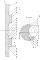
- FIG. 2 a section of a component support according to the invention of a turbomachine is shown.
- the turbomachine is preferably a stationary gas turbine and in particular an aircraft engine.
- the component support is located on the turbine side in the turbomachine and is formed for example by a stator-side annular housing 32 and a stator-side annular intermediate turbine housing.
- the intermediate turbine housing has a plurality of radially outwardly extending projections 34, 36, which serve as bearing sections and by means of which it at a axial support ring surface 38 of the housing 32 is supported.
- the housing 32 and the intermediate turbine housing are oriented in the embodiment shown here rotationally symmetrical and coaxial with the machine axis X of the turbomachine, which extends in the plane, namely orthogonal to the support ring surface 38th
- a plurality of groove-like recesses 40, 42, 44, 46 are introduced into the support ring surface 38.
- the recesses 40, 42, 44, 46 are equally spaced circumferentially and spaced from one another via uncontoured backup ring surface areas 48, 50, 52.
- the term "uncontoured" in the sense of the present invention means that the support ring surface areas 48, 50, 52 essentially continue an original contour of the support ring surface 38. Of course, local depressions are included in the backup ring surface areas 48, 50, 52. Also, the Stauerring vomareale 48, 50, 52 have a production-related surface roughness, which was not smoothed or only partially by subsequent machining. For example, the surfaces of the backup ring surface areas 48, 52 that support the bearing portions 34, 36 may be smoothed by finishing operations, such as finish grinding and / or by coating, while the surface of the intermediate support ring surface area 50 is substantially a production-related original surface roughness having.
- the bearing sections 34, 36 are distributed uniformly over the circumference. They have such a division in the circumferential direction that they each rest against a support ring surface area 48, 52 and are each spaced apart from each other via a support ring surface area 50. Between the respective adjacent bearing sections 34, 36 there is thus always an uncontoured support ring surface area 50.
- the support ring surface areas 48, 52, on which the bearing sections 34, 36 are supported are referred to as support ring surface sections.
- the bearing section-free support ring surface areas 50 are referred to as support ring surface areas.
- bearing portions 34, 36 have such an extent in the circumferential direction or width B that they are with their side edge portions 58, 60 in overlap with a respective recess 40, 42.
- the bearing portions 34, 36 with their side edge portions 58, 60 quasi spaced from the support ring surface 38, so that in a relative movement of the intermediate turbine housing to the housing 32, the side edge portions 58, 60 can not work into the housing or even can not be damaged.
- the bearing portions 34, 36 here have a rectangular cross-section with a flat bearing surface 62, via which it is in contact with the respective support ring surface portion 48, 52 and two radially extending side surfaces 64, 66, each with the contact surface 62, the side edge regions 58, 60 form.
- the recess 40, 42, 44, 46 each have a groove-like profile and extend with respect to the machine axis X in the radial direction. They are thus oriented in the direction of a relative movement of the intermediate turbine housing. In the radial direction, this groove-like contour is constant. They each have a base 68 with a basic radius R1, which in the exemplary embodiment shown here runs directly into the respective support ring surface section 48 and the support ring surface region 50.
- the recesses 40, 42, 44, 46 thus have virtually no side walls or go the side walls of the recesses 40, 42, 44, 46 stepless or flush in the bottom 68 over.
- Transition areas 70, 72 between the recesses 40, 42, 44, 46 and the respective support ring surface portion 48 and support ring surface area 50 are preferably each provided with a transition radius R2, R3.
- the recesses 40, 42, 44, 46 have a depth-to-width ratio d: w of 1: 5 to 1:20, preferably of about 1:10.
- the width w is thereby removed by a radial center plane 74 of the recesses 40, 42, 44, 46.
- the depth is removed from the midplane 74 intersection region with the base 68 to the adjacent support ring surface portion 48 and support ring surface region 50, respectively.
- the recesses 40, 42, 44, 46 have a total width W which is 0.25 times to 2 times the width B of the bearing portions 34, 36.
- the depth-to-width ratio d: w is set in particular via the basic radius R1.
- the base radius R1 can be interrupted in each case by a flat, not shown.
- the transition radii R2, R3 may be the same as in the embodiment shown here. In an alternative, not shown embodiment, the transition radii R2, R3 are different. The transition radii R2, R3 preferably correspond to 0.1 times to 1 times in the basic radius R1. Alternatively, the transition regions 70, 72 may be designed as a chamfer or edge.
- the component support can of course also be used on other stator-side components.
- the components can not be rotationally symmetrical.
- a component support of a turbomachine in particular an aircraft engine with at least two stator-side substantially annular components, which are in axial contact with each other, and are preferably aligned coaxially to the machine axis, wherein the first component has a plurality of radial groove-like recesses with which the second component with its projection-like positioning portions is laterally in overlap, and wherein between the respectively adjacent locating portions an uncontoured support annular surface portion is formed, and a turbomachine.
Landscapes
- Engineering & Computer Science (AREA)
- Mechanical Engineering (AREA)
- General Engineering & Computer Science (AREA)
- Structures Of Non-Positive Displacement Pumps (AREA)
- Turbine Rotor Nozzle Sealing (AREA)
- Mounting Of Bearings Or Others (AREA)
Abstract
Description
- Die Erfindung betrifft eine Bauteilabstützung nach dem Oberbegriff des Patentanspruchs 1 und eine Strömungsmaschine.
- In Strömungsmaschinen wie Dampfturbinen, stationären Gasturbinen oder Flugtriebwerken können zwischen zwei statorseitigen Bauteilen, die sich in Kontakt miteinander befinden, aufgrund von Vibration, unterschiedlichen Wärmeausdehnungen und der gleichen relative Bewegungen auftreten. In
Figur 1 ist eine bekannte Bauteilabstützung zwischen zwei sich in Anlage befindenden statorseitigen Bauteilen skizziert. Die Bauteile sind dabei nur ausschnittsweise und stark vereinfacht skizziert. Das eine Bauteil 1 ist ein Gehäusering, der koaxial zu einer in der Zeichenebene verlaufenden Maschinenachse X ausgerichtet ist. Das zweite Bauteil ist beispielsweise ein Zwischenturbinengehäuse, das ebenfalls koaxial zur Maschinenachse X ausgerichtet ist und über eine Vielzahl von sich radial nach außen erstreckenden Lagerabschnitten 2, 4 an einer Stützringfläche 6 des ersten Bauteils abgestützt ist. Zur Vermeidung von Kanteneffekten zwischen den Lagerabschnitten 2, 4 und der Stützringfläche 6 sind in der Stützringfläche 6 eine Vielzahl von Aussparungen 8, 10, 12 eingebracht, mit denen sich die Lagerabschnitte 2, 4 mit ihren Seitenkantenbereichen 14, 16 in Überlappung befinden. Die Aussparungen 8, 10, 12 sind in Umfangsrichtung gleichmäßig voneinander beabstandet und jeweils über einen unkonturierten und die Lagerabschnitte 2, 4 aufnehmenden Stützringflächenabschnitt 18, 20 voneinander beabstandet. Sie sind radial zur Maschinenachse X und somit in Bewegungsrichtung des Zwischenturbinengehäuses orientiert. Die Aussparungen 8, 10, 12 sind jeweils nutenartig und haben zwei steile Seitenwandungen 22, 24, die über einen flachen Grund 26 miteinander verbunden sind. Übergangsbereiche 28, 30 zwischen den Seitenwandungen 22, 24 und den Stützringflächenabschnitten 18, 20 sind verhältnismäßig scharfkantig ausgebildet. Mittels dieser nutenartigen Aussparungen lassen sich zwar Kanteneffekte zumindest verringern, jedoch führen die nutenartigen Aussparungen zu einer Veränderung der Strukturmechanik des Gehäuserings im Bereich der Stützringfläche. Zudem können beim Einbringen der Aussparungen Spannungen in den Gehäusering eingebracht werden. - In der
JP 59018213 A - Aufgabe der Erfindung ist es, eine alternative Bauteilabstützung einer Strömungsmaschine zu schaffen, die die vorgenannten Nachteile beseitigt und bei der ein Kanteneffekt zwischen zwei sich in Anlage befindenden statorseitigen Bauteilen verhindert wird. Des Weiteren ist es Aufgabe der Erfindung, eine Strömungsmaschine mit einer optimierten Bauteilabstützung zu schaffen.
- Diese Aufgabe wird gelöst durch eine Bauteilabstützung mit den Merkmalen des Patentanspruchs 1 und durch eine Strömungsmaschine mit den Merkmalen des Patentanspruchs 11.
- Eine erfindungsgemäße Bauteilabstützung einer Strömungsmaschine hat zumindest zwei statorseitige im Wesentlichen ringförmige Bauteile, die sich in axialer Anlage miteinander befinden und vorzugsweise koaxial zueinander ausgebildet sind. Das erste Bauteil hat eine Stützringfläche und das zweite Bauteil hat eine Vielzahl von über seinen Umfang verteilten Lagerabschnitten, mit denen es sich in Anlage mit der Stützringfläche befindet. Erfindungsgemäß ist in die Stützringfläche eine Vielzahl von im Wesentlichen radialen, rinnenartigen Aussparungen eingebracht, wobei sich jeder Lagerabschnitt mit seinen beiden Seitenkantenbereichen in Überlappung mit einer Aussparung befindet, und sich zwischen den jeweils benachbarten Lagerabschnitten ein unkonturierter Stützringflächenbereich erstreckt.
- Durch die erfindungsgemäße Abstützung werden Kanteneffekte an der Stützringfläche und an den Lagerabschnitten bei einer Relativbewegung der Bauteile, beispielsweise aufgrund von unterschiedlichen Wärmeausdehnungen, zueinander verhindert. Durch die rinnenartigen Aussparungen in Kombination mit den unkonturierten Stützringflächenbereichen zwischen den Lagerabschnitten erfolgt keine wesentliche bzw. keine Veränderung der Strukturmechanik des ersten Bauteils, sodass durch die rinnenartigen Aussparungen keine zusätzlichen Spannungen in das erste Bauteil eingebracht werden, auch nicht bei deren Einbringung in das erste Bauteil. Zudem lassen sich die rinnenartigen Aussparungen fertigungstechnisch einfach herstellen. Beispielsweise werden die rinnenartigen Aussparungen mittels einer mechanischen Bearbeitung wie Fräsen oder einer elektrochemischen bzw. galvanischen Bearbeitung herausgearbeitet.
- Bei einem bevorzugten Ausführungsbeispiel haben die Aussparungen ein Tiefen-Breiten-Verhältnis von 1: 5 bis 1:20. Die Tiefe wird dabei in axialer Richtung und die Breite in Umfangsrichtung abgetragen. Bei einem besonders günstigen Ausführungsbeispiel beträgt das Tiefen- Breiten-Verhältnis 1:10. Die Breite wird dabei von einer radialen Mittelebene der Aussparungen abgetragen, so dass die Aussparungen ähnlich einem Durchmesser zu einem Radius eine Gesamtbreite haben, die gleich 2mal der Breite ist.
- Bevorzugterweise haben die Aussparungen eine Gesamtbreite, die 0,25mal bis 2mal einer Breite der Lagerabschnitte ist.
- Eine optimale Anpassung des ersten Bauteils an eine aufzunehmende Stützlast kann dadurch erreicht werden, dass die Aussparungen jeweils unterschiedliche Übergangsradien im Übergangsbereich zu den unkonturierten Stützringflächenbereichen und zu Stützringflächenabschnitten aufweisen, an denen die Lagerabschnitte abgestützt sind bzw. die die Lagerabschnitte aufnehmen.
- Bei einem alternativen Ausführungsbeispiel haben die Aussparungen jeweils gleiche Übergangsradien im Übergangsbereich zu den unkonturierten Stützringflächenbereichen und zu den Lagerabschnitten aufnehmenden Stützringflächenabschnitten. Ein derartiges Ausführungsbeispiel ist aufgrund der gleichen Übergangsradien einfacher herzustellen als das vorhergehende Ausführungsbeispiel mit den unterschiedlichen Übergangsradien.
- Aus strukturmechanischer Sicht ist es günstig, wenn die Übergangsradien 0,1mal bis 1mal einem Grundradius der Aussparungen entsprechen.
- Alternativ sind die Übergangsbereiche von den Aussparungen zu den unkonturierten Stützringflächenbereichen und zu den die Lagerabschnitte aufnehmenden Stützringflächenabschnitten als Fasen oder Kanten ausgebildet. Fasen bzw. Kanten sind fertigungstechnisch einfach auszubilden.
- Bei einem Ausführungsbeispiel ist der Grundradius durch eine Flachstelle unterbrochen.
- Vorteilhafterweise sind die zumindest zwei Bauteile koaxial zueinander ausgerichtet.
- Insbesondere können die zumindest zwei Bauteile rotationssymmetrisch ausgebildet sein. Dies erleichtert die Ausrichtung der Bauteile zueinander.
- Eine erfindungsgemäße Strömungsmaschine hat zumindest eine erfindungsgemäße Bauteilabstützung, wodurch Kanteneffekte zwischen sich in Anlage befindenden statorseitigen Bauteilen verhindert werden.
- Sonstige vorteilhafte Ausführungsbeispiele der Erfindung sind Gegenstand weiterer Unteransprüche.
- Im Folgenden wird ein bevorzugtes Ausführungsbeispiel der Erfindung anhand schematischer Darstellungen näher erläutert. Es zeigen:
- Figur 1
- einen Ausschnitt einer bekannten Abstützung von zwei Bauteilen einer Strömungsmaschine,
- Figur 2
- einen Ausschnitt einer erfindungsgemäßen Bauteilabstützung einer Strömungsmaschine, und
- Figur 3
- eine Detaildarstellung aus
Figur 2 . - In
Figur 2 ist ein Ausschnitt einer erfindungsgemäßen Bauteilabstützung einer Strömungsmaschine gezeigt. Die Strömungsmaschine ist bevorzugterweise eine stationäre Gasturbine und insbesondere ein Flugtriebwerk. Die Bauteilabstützung befindet sich turbinenseitig in der Strömungsmaschine und wird beispielsweise von einem statorseitigen ringförmigen Gehäuse 32 und einem statorseitigen ringförmigen Zwischenturbinengehäuse gebildet. Das Zwischenturbinengehäuse hat eine Vielzahl von sich radial nach außen erstreckende Vorsprünge 34, 36, die als Lagerabschnitte dienen und mittels denen es an einer axialen Stützringfläche 38 des Gehäuses 32 abgestützt ist. Das Gehäuse 32 und das Zwischenturbinengehäuse sind in dem hier gezeigten Ausführungsbeispiel rotationssymmetrisch und koaxial zur Maschinenachse X der Strömungsmaschine orientiert, die sich in der Zeichenebene erstreckt, und zwar orthogonal zur Stützringfläche 38. - Zur Vermeidung von Kanteneffekten im Bereich der Lagerabschnitte 34, 36 sind in der Stützringfläche 38 eine Vielzahl von rinnenartigen Aussparungen 40, 42, 44, 46 eingebracht. Die Aussparungen 40, 42, 44, 46 sind in Umfangsrichtung gleichmäßig voneinander beabstandet und über unkonturierte Stützringflächenareale 48, 50, 52 voneinander beabstandet.
- Der Begriff "unkonturiert" bedeutet im Sinne der vorliegenden Erfindung, dass die Stützringflächenareale 48, 50, 52 im Wesentlichen eine ursprüngliche Kontur der Stützringfläche 38 fortführen. Selbstverständlich sind lokale Vertiefungen in den Stützringflächenarealen 48, 50, 52 umfasst. Auch können die Stützringflächenareale 48, 50, 52 eine fertigungsbedingte Oberflächenrauhigkeit aufweisen, welche nicht oder nur abschnittsweise durch Nachbearbearbeitung geglättet wurde. Beispielsweise können die Oberflächen der Stützringflächenareale 48, 52, die die Lagerabschnitte 34, 36 abstützen, durch Feinbearbeitungsschritte, wie zum Beispiel Feinschleifen und/oder durch Beschichten geglättet werden bzw. worden sein, während die Oberfläche des dazwischenliegenden Stützringflächenareals 50 im Wesentlichen eine herstellungsbedingte ursprüngliche Oberflächenrauhigkeit aufweist.
- Die Lagerabschnitte 34, 36 sind gleichmäßig über den Umfang verteilt. Sie haben in Umfangsrichtung eine derartige Teilung, dass sie jeweils an einem Stützringflächenareal 48, 52 anliegen und dabei jeweils über ein Stützringflächenareal 50 voneinander beabstandet sind. Zwischen den jeweils benachbarten Lagerabschnitten 34, 36 befindet sich somit stets ein unkonturiertes Stützringflächenareal 50. Aus Gründen der Übersichtlichkeit werden die Stützringflächenareale 48, 52, an denen die Lagerabschnitte 34, 36 abgestützt sind, als Stützringflächenabschnitte bezeichnet. Die lagerabschnittsfreien Stützringflächenareale 50 werden als Stützringflächenbereiche bezeichnet.
- Aus Gründen der Übersichtlichkeit ist im Folgenden lediglich der in
Figur 2 gezeigte linke Lagerabschnitt 34 entsprechend beziffert. Die Lagerabschnitte 34, 36 haben eine derartige Erstreckung in Umfangsrichtung bzw. Breite B, das sie sich mit ihren Seitenkantenbereichen 58, 60 in Überlappung mit jeweils einer Aussparung 40, 42 befinden. Hierdurch sind die Lagerabschnitte 34, 36 mit ihren Seitenkantenbereichen 58, 60 von der Stützringfläche 38 quasi beabstandet, so dass sich bei einer Relativbewegung des Zwischenturbinengehäuses zum Gehäuse 32 die Seitenkantenbereiche 58, 60 nicht in das Gehäuse einarbeiten können bzw. selbst nicht beschädigt werden können. Die Lagerabschnitte 34, 36 haben hier einen rechteckigen Querschnitt mit einer ebenen Anlagefläche 62, über die sie sich in Kontakt mit dem jeweiligen Stützringflächenabschnitt 48, 52 befindet und zwei sich in radialer Richtung erstreckende Seitenflächen 64, 66, die jeweils mit der Anlagefläche 62 die Seitenkantenbereiche 58, 60 bilden. - Wie in der Detaildarstellung in
Figur 3 anhand der Aussparung 42 stellvertretend für alle Aussparungen 40, 42, 44, 46 verdeutlicht, haben die Aussparungen 40, 42, 44, 46 jeweils ein rinnenartiges Profil und erstrecken sich bezogen auf die Maschinenachse X in Radialrichtung. Sie sind somit in Richtung einer Relativbewegung des Zwischenturbinengehäuses orientiert. In Radialrichtung ist diese rinnenartige Kontur konstant. Sie haben jeweils einen Grund 68 mit einem Grundradius R1, der in dem hier gezeigten Ausführungsbeispiel direkt in den jeweiligen Stützringflächenabschnitt 48 und den Stützringflächenbereich 50 ausläuft. Die Aussparungen 40, 42, 44, 46 weisen somit quasi keine Seitenwandungen auf bzw. gehen die Seitenwandungen der Aussparungen 40, 42, 44, 46 stufenlos bzw. bündig in den Grund 68 über. Übergangsbereiche 70, 72 zwischen den Aussparungen 40, 42, 44, 46 und dem jeweiligen Stützringflächenabschnitt 48 und Stützringflächenbereich 50 sind bevorzugterweise mit jeweils einem Übergangsradius R2, R3 versehen. - Die Aussparungen 40, 42, 44, 46 haben eine Tiefen-Breiten-Verhältnis d:w von 1:5 bis 1: 20, bevorzugterweise von etwa 1:10. Die Breite w wird dabei von einer radialen Mittelebene 74 der Aussparungen 40, 42, 44, 46 abgetragen. Die Tiefe wird vom Schnittbereich der Mittelebene 74 mit dem Grund 68 zum angrenzenden Stützringflächenabschnitt 48 bzw. Stützringflächenbereich 50 abgetragen. Bevorzugterweise haben die Aussparungen 40, 42, 44, 46 eine Gesamtbreite W, die 0,25mal bis 2mal der Breite B der Lagerabschnitte 34, 36 ist. Das Tiefen-Breiten-Verhältnis d:w wird insbesondere über den Grundradius R1 eingestellt.
- Der Grundradius R1 kann dabei jeweils von einer nicht gezeigten Flachstelle unterbrochen sein.
- Die Übergangsradien R2, R3 können wie in dem hier gezeigten Ausführungsbeispiel gleich ausgeführt sein. Bei einem alternativen, nicht gezeigten Ausführungsbeispiel sind die Übergangsradien R2, R3 unterschiedlich. Bevorzugterweise entsprechen die Übergangsradien R2, R3 0,1mal bis 1mal im Grundradius R1. Alternativ können die Übergangsbereiche 70, 72 als Fase oder Kante ausgeführt sein.
- Neben der hier beispielhaft erläuterten Anwendung der erfindungsgemäßen Bauteilabstützung zur Abstützung eines Zwischenturbinengehäuses an einem Gehäusering, kann die Bauteilabstützung selbstverständlich auch an anderen statorseitigen Bauteilen verwendet werden. Insbesondere können die Bauteile nicht rotationssymmetrisch sein.
- Offenbart ist eine Bauteilabstützung einer Strömungsmaschine, insbesondere ein Flugtriebwerk mit zumindest zwei statorseitigen im Wesentlichen ringförmigen Bauteilen, die sich in axialer Anlage miteinander befinden, und vorzugsweise koaxial zur Maschinenachse ausgerichtet sind, wobei das erste Bauteil eine Vielzahl von radialen rinnenartigen Aussparungen aufweist, mit denen sich das zweite Bauteil mit seinen vorsprungartigen Lageabschnitten seitlich in Überlappung befindet, und wobei zwischen den jeweils benachbarten Lageabschnitten ein unkonturierter Stützringflächenabschnitt ausgebildet ist, sowie eine Strömungsmaschine.
-
- 1
- Gehäusering
- 2
- Vorsprung / Lagerabschnitt
- 4
- Vorsprung / Lagerabschnitt
- 6
- Stützringfläche
- 8
- nutenartigen Aussparung
- 10
- nutenartigen Aussparung
- 12
- nutenartigen Aussparung
- 14
- Seitenkantenbereich
- 16
- Seitenkantenbereich
- 18
- Stützringflächenabschnitt
- 20
- Stützringflächenabschnitt
- 22
- Seitenwandung
- 24
- Seitenwandung
- 26
- Grund
- 28
- Übergangsbereich
- 30
- Übergangsbereich
- 32
- Gehäuse
- 34
- Lagerabschnitt
- 36
- Lagerabschnitt
- 38
- Stützringfläche
- 40
- Aussparung
- 42
- Aussparung
- 44
- Aussparung
- 46
- Aussparung
- 48
- Stützringflächenareal / Stützringflächenabschnitt
- 50
- Stützringflächenareal / Stützringflächenbereich
- 52
- Stützringflächenareal / Stützringflächenabschnitt
- 58
- Seitenkantenbereich
- 60
- Seitenkantenbereich
- 62
- Anlagefläche
- 64
- Seitenfläche
- 66
- Seitenfläche
- 68
- Grund
- 70
- Übergangsbereich
- 72
- Übergangsbereich
- 74
- Mittelebene
- R1
- Grundradius
- R2
- Übergangsradius
- R3
- Übergangsradius
- B
- Breite Lagerabschnitt
- d
- Tiefe Aussparung
- w
- Breite Aussparung, abgetragen von Mittellinie
- W
- Gesamtbreite Aussparung
- X
- Maschinenachse
Claims (11)
- Bauteilabstützung einer Strömungsmaschine, mit zumindest zwei statorseitigen, im Wesentlichen ringförmigen Bauteilen (32), die sich in axialer Anlage miteinander befinden, wobei das erste Bauteil (1) eine Stützringfläche (38) hat und das zweite Bauteil eine Vielzahl von über seinen Umfang verteilten Lagerabschnitten (34, 36) hat, mit denen es sich in Anlage mit der Stützringfläche (38) befindet, dadurch gekennzeichnet, dass in die Stützringfläche (38) eine Vielzahl von im Wesentlichen radialen rinnenartigen Aussparungen (40, 42, 44, 46) eingebracht ist, wobei sich jeder Lagerabschnitt (34, 36) mit seinen beiden Seitenkantbereichen (58, 60) in Überlappung mit einer Aussparung (40, 42, 44, 46) befindet und sich zwischen den jeweils benachbarten Lagerabschnitten (34, 36) ein unkonturierter Stützringflächenbereich (50) erstreckt.
- Bauteilabstützung nach Anspruch 1, wobei die Aussparungen (40, 42, 44, 46) ein Tiefenzu Breitenverhältnis (d:w) von 1:5 bis 1:20, bevorzugterweise von etwa 1:10 haben.
- Bauteilabstützung nach Anspruch 1 oder 2, wobei die Aussparungen (40, 42, 44, 46) eine Gesamtbreite (W) haben, die 0,25mal bis 2mal einer Breite (B) der Lagerabschnitte (34, 36) ist.
- Bauteilabstützung nach Anspruch 1, 2 oder 3, wobei die Aussparungen (40, 42, 44, 46) jeweils unterschiedliche Übergangsradien (R2, R3) im Übergangsbereich (70, 72) zu den unkonturierten Stützringflächenbereichen (50) und zu die Lagerabschnitte (34, 36) aufnehmenden Stützringflächenabschnitten (48, 52) haben.
- Bauteilabstützung nach Anspruch 1, 2 oder 3, wobei die Aussparungen (40, 42, 44, 46) jeweils gleiche Übergangsradien (R2, R3) im Übergangsbereich (70, 72) zu den unkonturierten Stützringflächenbereichen (50) und zu die Lagerabschnitte aufnehmenden Stützringflächenabschnitten (48, 52) haben.
- Bauteilabstützung nach Anspruch 4 oder 5, wobei die Übergangsradien (R2, R3) 0,1mal bis 1mal einem Grundradius (R1) der Aussparungen (40, 42, 44, 46) entsprechen.
- Bauteilabstützung nach Anspruch 1, 2 oder 3, wobei Übergangsbereiche (70, 72) von den Aussparungen (40, 42, 44, 46) zu den unkonturierten Stützringflächenbereichen (50) und zu die Lagerabschnitte (34, 36) aufnehmenden Stützringflächenabschnitten (48, 52) als Fasen oder Kanten ausgebildet sind.
- Bauteilabstützung nach einem der vorhergehenden Ansprüche, wobei der Grundradius (R1) durch eine Flachstelle unterbrochen ist.
- Bauteilabstützung nach einem der vorhergehenden Ansprüche, wobei die zumindest zwei statorseitigen Bauteile (32) im Wesentlichen koaxial zueinander ausgerichtet sind.
- Bauteilabstützung nach einem der vorhergehenden Ansprüche, wobei die zumindest zwei statorseitigen Bauteile (32) im Wesentlichen rotationssymmetrisch ausgebildet sind.
- Strömungsmaschine mit einer Bauteilabstützung nach einem der vorhergehenden Ansprüche.
Priority Applications (3)
| Application Number | Priority Date | Filing Date | Title |
|---|---|---|---|
| ES13187698.9T ES2620486T3 (es) | 2013-10-08 | 2013-10-08 | Soporte de componente y turbomáquina |
| EP13187698.9A EP2860361B1 (de) | 2013-10-08 | 2013-10-08 | Bauteilabstützung und Strömungsmaschine |
| US14/508,675 US9752455B2 (en) | 2013-10-08 | 2014-10-07 | Component support and turbomachine |
Applications Claiming Priority (1)
| Application Number | Priority Date | Filing Date | Title |
|---|---|---|---|
| EP13187698.9A EP2860361B1 (de) | 2013-10-08 | 2013-10-08 | Bauteilabstützung und Strömungsmaschine |
Publications (2)
| Publication Number | Publication Date |
|---|---|
| EP2860361A1 true EP2860361A1 (de) | 2015-04-15 |
| EP2860361B1 EP2860361B1 (de) | 2017-03-01 |
Family
ID=49356208
Family Applications (1)
| Application Number | Title | Priority Date | Filing Date |
|---|---|---|---|
| EP13187698.9A Not-in-force EP2860361B1 (de) | 2013-10-08 | 2013-10-08 | Bauteilabstützung und Strömungsmaschine |
Country Status (3)
| Country | Link |
|---|---|
| US (1) | US9752455B2 (de) |
| EP (1) | EP2860361B1 (de) |
| ES (1) | ES2620486T3 (de) |
Citations (4)
| Publication number | Priority date | Publication date | Assignee | Title |
|---|---|---|---|---|
| JPS5918213A (ja) | 1982-07-21 | 1984-01-30 | Toshiba Corp | タ−ビンケ−シング |
| US20050002779A1 (en) * | 2003-07-04 | 2005-01-06 | Ishikawajima-Harima Heavy Industries Co., Ltd. | Turbine shroud segment |
| FR2887920A1 (fr) * | 2005-06-29 | 2007-01-05 | Snecma | Dispositif de fixation de secteurs d'anneau sur un carter de turbine |
| WO2013163505A1 (en) * | 2012-04-27 | 2013-10-31 | General Electric Company | Shroud assembly and seal for a gas turbine engine |
Family Cites Families (15)
| Publication number | Priority date | Publication date | Assignee | Title |
|---|---|---|---|---|
| US2211866A (en) | 1939-03-31 | 1940-08-20 | Westinghouse Electric & Mfg Co | Turbine blade fastening |
| DE1062881B (de) | 1956-08-24 | 1959-08-06 | Krantz H Fa | Axialventilator mit bei Stillstand im Nabenkranz auf verschiedene Anstellwinkel einstellbaren Laufschaufeln |
| US4497612A (en) | 1983-11-25 | 1985-02-05 | General Electric Company | Steam turbine wheel antirotation means |
| JPH0639890B2 (ja) | 1984-01-24 | 1994-05-25 | 株式会社日立製作所 | 焼嵌ロータを有する低圧タービンの起動方法及び装置 |
| US5067877A (en) | 1990-09-11 | 1991-11-26 | United Technologies Corporation | Fan blade axial retention device |
| US5141401A (en) | 1990-09-27 | 1992-08-25 | General Electric Company | Stress-relieved rotor blade attachment slot |
| DE4435268A1 (de) | 1994-10-01 | 1996-04-04 | Abb Management Ag | Beschaufelter Rotor einer Turbomaschine |
| DE4436729A1 (de) | 1994-10-14 | 1996-04-18 | Abb Management Ag | Beschaufelter Rotor |
| DE19728085A1 (de) | 1997-07-02 | 1999-01-07 | Asea Brown Boveri | Fügeverbindung zwischen zwei Fügepartnern sowie deren Verwendung |
| DE10030820A1 (de) | 2000-06-23 | 2002-01-03 | Alstom Power Nv | Labyrinthdichtung für eine rotierende Welle |
| US6352405B1 (en) * | 2000-08-09 | 2002-03-05 | General Electric Company | Interchangeable turbine diaphragm halves and related support system |
| DE10357134A1 (de) | 2003-12-06 | 2005-06-30 | Alstom Technology Ltd | Rotor für einen Verdichter |
| EP2045444B1 (de) | 2007-10-01 | 2015-11-18 | Alstom Technology Ltd | Laufschaufel, Verfahren zur Herstellung einer Laufschaufel, sowie Verdichter mit einer solchen Laufschaufel |
| JP5538569B2 (ja) | 2010-02-19 | 2014-07-02 | ボーグワーナー インコーポレーテッド | タービンホイール、およびタービンホイールを製造するための方法 |
| JP5538337B2 (ja) | 2011-09-29 | 2014-07-02 | 株式会社日立製作所 | 動翼 |
-
2013
- 2013-10-08 EP EP13187698.9A patent/EP2860361B1/de not_active Not-in-force
- 2013-10-08 ES ES13187698.9T patent/ES2620486T3/es active Active
-
2014
- 2014-10-07 US US14/508,675 patent/US9752455B2/en not_active Expired - Fee Related
Patent Citations (4)
| Publication number | Priority date | Publication date | Assignee | Title |
|---|---|---|---|---|
| JPS5918213A (ja) | 1982-07-21 | 1984-01-30 | Toshiba Corp | タ−ビンケ−シング |
| US20050002779A1 (en) * | 2003-07-04 | 2005-01-06 | Ishikawajima-Harima Heavy Industries Co., Ltd. | Turbine shroud segment |
| FR2887920A1 (fr) * | 2005-06-29 | 2007-01-05 | Snecma | Dispositif de fixation de secteurs d'anneau sur un carter de turbine |
| WO2013163505A1 (en) * | 2012-04-27 | 2013-10-31 | General Electric Company | Shroud assembly and seal for a gas turbine engine |
Also Published As
| Publication number | Publication date |
|---|---|
| US20150098799A1 (en) | 2015-04-09 |
| ES2620486T3 (es) | 2017-06-28 |
| US9752455B2 (en) | 2017-09-05 |
| EP2860361B1 (de) | 2017-03-01 |
Similar Documents
| Publication | Publication Date | Title |
|---|---|---|
| DE102013204714A1 (de) | Honverfahren und Honwerkzeug | |
| DE10144649A1 (de) | Verfahren zur drallfreien spanenden Bearbeitung von rotationssymmetrischen Flächen | |
| EP2982470B1 (de) | Verfahren zur herstellung eines rotors einer ladeeinrichtung | |
| EP1963693B1 (de) | Verfahren zur herstellung eines wälzlagerringes | |
| DE102014212941A1 (de) | Honwerkzeug und Honverfahren | |
| DE102016222030A1 (de) | Wälzlageranordnung | |
| EP2814636B1 (de) | Verfahren zum erhöhen der festigkeit von wellen, insbesondere von kurbelwellen | |
| EP3259099B1 (de) | Honverfahren zum formhonen und bearbeitungsanlage | |
| EP3299116B1 (de) | Verfahren zur herstellung oder zur reparatur eines bauteils einer rotationsmaschine sowie bauteil hergestellt oder repariert nach einem solchen verfahren | |
| WO2019052850A1 (de) | Aufrauwerkzeug und verfahren zu dessen herstellung | |
| EP2976174B1 (de) | Reibelement, reibwerkzeug und verfahren zu dessen herstellung | |
| EP2860361B1 (de) | Bauteilabstützung und Strömungsmaschine | |
| DE102013011817A1 (de) | Flexible Führungsbuchse | |
| DE102012224020A1 (de) | Lager | |
| EP3085492B1 (de) | Schleifwerkzeug | |
| EP1798376B1 (de) | Sekundärfluidkanalherstellungsverfahren | |
| EP4054800B1 (de) | Honwerkzeug und verfahren zur bearbeitung eines lagerteils | |
| EP3380739B1 (de) | Verfahren zum fertigen eines massivbauteils sowie ein massivbauteil | |
| DE102014205814B4 (de) | Verfahren zum Herstellen eines Kammteils eines Käfigs, Verfahren zum Erstellen von Steuerdaten für eine Werkzeugmaschine zum Herstellen eines Kammteils eines Käfigs, Programm und Käfig | |
| DE102019107758A1 (de) | Käfig - und walzenbaugruppe | |
| EP3325202A1 (de) | Verfahren und vorrichtung zum feinbearbeiten von vorbearbeiteten lagersitzen der hauptlager und hublager von kurbelwellen | |
| DE102013215967A1 (de) | Schneidwerkzeug, Verfahren und Verwendung des Schneidwerkzeugs zum Bearbeiten eines Lagerrings | |
| DE102010063034B4 (de) | Verfahren zum Bearbeiten eines geteilten Lagerrings | |
| DE102006046162A1 (de) | Axialgleitlager und Verfahren zur Herstellung einer Reibfläche einer Reibpaarung | |
| EP4403794A1 (de) | Einteilige zahnwelle |
Legal Events
| Date | Code | Title | Description |
|---|---|---|---|
| PUAI | Public reference made under article 153(3) epc to a published international application that has entered the european phase |
Free format text: ORIGINAL CODE: 0009012 |
|
| 17P | Request for examination filed |
Effective date: 20131008 |
|
| AK | Designated contracting states |
Kind code of ref document: A1 Designated state(s): AL AT BE BG CH CY CZ DE DK EE ES FI FR GB GR HR HU IE IS IT LI LT LU LV MC MK MT NL NO PL PT RO RS SE SI SK SM TR |
|
| AX | Request for extension of the european patent |
Extension state: BA ME |
|
| R17P | Request for examination filed (corrected) |
Effective date: 20150915 |
|
| RBV | Designated contracting states (corrected) |
Designated state(s): AL AT BE BG CH CY CZ DE DK EE ES FI FR GB GR HR HU IE IS IT LI LT LU LV MC MK MT NL NO PL PT RO RS SE SI SK SM TR |
|
| GRAP | Despatch of communication of intention to grant a patent |
Free format text: ORIGINAL CODE: EPIDOSNIGR1 |
|
| INTG | Intention to grant announced |
Effective date: 20161116 |
|
| GRAS | Grant fee paid |
Free format text: ORIGINAL CODE: EPIDOSNIGR3 |
|
| GRAA | (expected) grant |
Free format text: ORIGINAL CODE: 0009210 |
|
| AK | Designated contracting states |
Kind code of ref document: B1 Designated state(s): AL AT BE BG CH CY CZ DE DK EE ES FI FR GB GR HR HU IE IS IT LI LT LU LV MC MK MT NL NO PL PT RO RS SE SI SK SM TR |
|
| REG | Reference to a national code |
Ref country code: GB Ref legal event code: FG4D Free format text: NOT ENGLISH |
|
| REG | Reference to a national code |
Ref country code: CH Ref legal event code: EP Ref country code: AT Ref legal event code: REF Ref document number: 871619 Country of ref document: AT Kind code of ref document: T Effective date: 20170315 |
|
| REG | Reference to a national code |
Ref country code: IE Ref legal event code: FG4D Free format text: LANGUAGE OF EP DOCUMENT: GERMAN |
|
| REG | Reference to a national code |
Ref country code: DE Ref legal event code: R096 Ref document number: 502013006503 Country of ref document: DE |
|
| REG | Reference to a national code |
Ref country code: ES Ref legal event code: FG2A Ref document number: 2620486 Country of ref document: ES Kind code of ref document: T3 Effective date: 20170628 |
|
| REG | Reference to a national code |
Ref country code: NL Ref legal event code: MP Effective date: 20170301 |
|
| REG | Reference to a national code |
Ref country code: LT Ref legal event code: MG4D |
|
| PG25 | Lapsed in a contracting state [announced via postgrant information from national office to epo] |
Ref country code: LT Free format text: LAPSE BECAUSE OF FAILURE TO SUBMIT A TRANSLATION OF THE DESCRIPTION OR TO PAY THE FEE WITHIN THE PRESCRIBED TIME-LIMIT Effective date: 20170301 Ref country code: NO Free format text: LAPSE BECAUSE OF FAILURE TO SUBMIT A TRANSLATION OF THE DESCRIPTION OR TO PAY THE FEE WITHIN THE PRESCRIBED TIME-LIMIT Effective date: 20170601 Ref country code: GR Free format text: LAPSE BECAUSE OF FAILURE TO SUBMIT A TRANSLATION OF THE DESCRIPTION OR TO PAY THE FEE WITHIN THE PRESCRIBED TIME-LIMIT Effective date: 20170602 Ref country code: FI Free format text: LAPSE BECAUSE OF FAILURE TO SUBMIT A TRANSLATION OF THE DESCRIPTION OR TO PAY THE FEE WITHIN THE PRESCRIBED TIME-LIMIT Effective date: 20170301 Ref country code: HR Free format text: LAPSE BECAUSE OF FAILURE TO SUBMIT A TRANSLATION OF THE DESCRIPTION OR TO PAY THE FEE WITHIN THE PRESCRIBED TIME-LIMIT Effective date: 20170301 |
|
| PG25 | Lapsed in a contracting state [announced via postgrant information from national office to epo] |
Ref country code: SE Free format text: LAPSE BECAUSE OF FAILURE TO SUBMIT A TRANSLATION OF THE DESCRIPTION OR TO PAY THE FEE WITHIN THE PRESCRIBED TIME-LIMIT Effective date: 20170301 Ref country code: BG Free format text: LAPSE BECAUSE OF FAILURE TO SUBMIT A TRANSLATION OF THE DESCRIPTION OR TO PAY THE FEE WITHIN THE PRESCRIBED TIME-LIMIT Effective date: 20170601 Ref country code: RS Free format text: LAPSE BECAUSE OF FAILURE TO SUBMIT A TRANSLATION OF THE DESCRIPTION OR TO PAY THE FEE WITHIN THE PRESCRIBED TIME-LIMIT Effective date: 20170301 Ref country code: LV Free format text: LAPSE BECAUSE OF FAILURE TO SUBMIT A TRANSLATION OF THE DESCRIPTION OR TO PAY THE FEE WITHIN THE PRESCRIBED TIME-LIMIT Effective date: 20170301 |
|
| PG25 | Lapsed in a contracting state [announced via postgrant information from national office to epo] |
Ref country code: NL Free format text: LAPSE BECAUSE OF FAILURE TO SUBMIT A TRANSLATION OF THE DESCRIPTION OR TO PAY THE FEE WITHIN THE PRESCRIBED TIME-LIMIT Effective date: 20170301 |
|
| REG | Reference to a national code |
Ref country code: FR Ref legal event code: PLFP Year of fee payment: 5 |
|
| PG25 | Lapsed in a contracting state [announced via postgrant information from national office to epo] |
Ref country code: EE Free format text: LAPSE BECAUSE OF FAILURE TO SUBMIT A TRANSLATION OF THE DESCRIPTION OR TO PAY THE FEE WITHIN THE PRESCRIBED TIME-LIMIT Effective date: 20170301 Ref country code: RO Free format text: LAPSE BECAUSE OF FAILURE TO SUBMIT A TRANSLATION OF THE DESCRIPTION OR TO PAY THE FEE WITHIN THE PRESCRIBED TIME-LIMIT Effective date: 20170301 Ref country code: IT Free format text: LAPSE BECAUSE OF FAILURE TO SUBMIT A TRANSLATION OF THE DESCRIPTION OR TO PAY THE FEE WITHIN THE PRESCRIBED TIME-LIMIT Effective date: 20170301 Ref country code: CZ Free format text: LAPSE BECAUSE OF FAILURE TO SUBMIT A TRANSLATION OF THE DESCRIPTION OR TO PAY THE FEE WITHIN THE PRESCRIBED TIME-LIMIT Effective date: 20170301 Ref country code: SK Free format text: LAPSE BECAUSE OF FAILURE TO SUBMIT A TRANSLATION OF THE DESCRIPTION OR TO PAY THE FEE WITHIN THE PRESCRIBED TIME-LIMIT Effective date: 20170301 |
|
| PG25 | Lapsed in a contracting state [announced via postgrant information from national office to epo] |
Ref country code: SM Free format text: LAPSE BECAUSE OF FAILURE TO SUBMIT A TRANSLATION OF THE DESCRIPTION OR TO PAY THE FEE WITHIN THE PRESCRIBED TIME-LIMIT Effective date: 20170301 Ref country code: PT Free format text: LAPSE BECAUSE OF FAILURE TO SUBMIT A TRANSLATION OF THE DESCRIPTION OR TO PAY THE FEE WITHIN THE PRESCRIBED TIME-LIMIT Effective date: 20170703 Ref country code: PL Free format text: LAPSE BECAUSE OF FAILURE TO SUBMIT A TRANSLATION OF THE DESCRIPTION OR TO PAY THE FEE WITHIN THE PRESCRIBED TIME-LIMIT Effective date: 20170301 Ref country code: IS Free format text: LAPSE BECAUSE OF FAILURE TO SUBMIT A TRANSLATION OF THE DESCRIPTION OR TO PAY THE FEE WITHIN THE PRESCRIBED TIME-LIMIT Effective date: 20170701 |
|
| REG | Reference to a national code |
Ref country code: DE Ref legal event code: R097 Ref document number: 502013006503 Country of ref document: DE |
|
| PLBE | No opposition filed within time limit |
Free format text: ORIGINAL CODE: 0009261 |
|
| STAA | Information on the status of an ep patent application or granted ep patent |
Free format text: STATUS: NO OPPOSITION FILED WITHIN TIME LIMIT |
|
| PG25 | Lapsed in a contracting state [announced via postgrant information from national office to epo] |
Ref country code: DK Free format text: LAPSE BECAUSE OF FAILURE TO SUBMIT A TRANSLATION OF THE DESCRIPTION OR TO PAY THE FEE WITHIN THE PRESCRIBED TIME-LIMIT Effective date: 20170301 |
|
| 26N | No opposition filed |
Effective date: 20171204 |
|
| PG25 | Lapsed in a contracting state [announced via postgrant information from national office to epo] |
Ref country code: SI Free format text: LAPSE BECAUSE OF FAILURE TO SUBMIT A TRANSLATION OF THE DESCRIPTION OR TO PAY THE FEE WITHIN THE PRESCRIBED TIME-LIMIT Effective date: 20170301 |
|
| PG25 | Lapsed in a contracting state [announced via postgrant information from national office to epo] |
Ref country code: MC Free format text: LAPSE BECAUSE OF FAILURE TO SUBMIT A TRANSLATION OF THE DESCRIPTION OR TO PAY THE FEE WITHIN THE PRESCRIBED TIME-LIMIT Effective date: 20170301 |
|
| REG | Reference to a national code |
Ref country code: CH Ref legal event code: PL |
|
| REG | Reference to a national code |
Ref country code: IE Ref legal event code: MM4A |
|
| PG25 | Lapsed in a contracting state [announced via postgrant information from national office to epo] |
Ref country code: CH Free format text: LAPSE BECAUSE OF NON-PAYMENT OF DUE FEES Effective date: 20171031 Ref country code: LU Free format text: LAPSE BECAUSE OF NON-PAYMENT OF DUE FEES Effective date: 20171008 Ref country code: LI Free format text: LAPSE BECAUSE OF NON-PAYMENT OF DUE FEES Effective date: 20171031 |
|
| REG | Reference to a national code |
Ref country code: BE Ref legal event code: MM Effective date: 20171031 |
|
| PG25 | Lapsed in a contracting state [announced via postgrant information from national office to epo] |
Ref country code: BE Free format text: LAPSE BECAUSE OF NON-PAYMENT OF DUE FEES Effective date: 20171031 |
|
| PG25 | Lapsed in a contracting state [announced via postgrant information from national office to epo] |
Ref country code: MT Free format text: LAPSE BECAUSE OF FAILURE TO SUBMIT A TRANSLATION OF THE DESCRIPTION OR TO PAY THE FEE WITHIN THE PRESCRIBED TIME-LIMIT Effective date: 20170301 |
|
| REG | Reference to a national code |
Ref country code: FR Ref legal event code: PLFP Year of fee payment: 6 |
|
| PG25 | Lapsed in a contracting state [announced via postgrant information from national office to epo] |
Ref country code: IE Free format text: LAPSE BECAUSE OF NON-PAYMENT OF DUE FEES Effective date: 20171008 |
|
| PG25 | Lapsed in a contracting state [announced via postgrant information from national office to epo] |
Ref country code: HU Free format text: LAPSE BECAUSE OF FAILURE TO SUBMIT A TRANSLATION OF THE DESCRIPTION OR TO PAY THE FEE WITHIN THE PRESCRIBED TIME-LIMIT; INVALID AB INITIO Effective date: 20131008 |
|
| PG25 | Lapsed in a contracting state [announced via postgrant information from national office to epo] |
Ref country code: CY Free format text: LAPSE BECAUSE OF FAILURE TO SUBMIT A TRANSLATION OF THE DESCRIPTION OR TO PAY THE FEE WITHIN THE PRESCRIBED TIME-LIMIT Effective date: 20170301 |
|
| PG25 | Lapsed in a contracting state [announced via postgrant information from national office to epo] |
Ref country code: MK Free format text: LAPSE BECAUSE OF FAILURE TO SUBMIT A TRANSLATION OF THE DESCRIPTION OR TO PAY THE FEE WITHIN THE PRESCRIBED TIME-LIMIT Effective date: 20170301 |
|
| REG | Reference to a national code |
Ref country code: AT Ref legal event code: MM01 Ref document number: 871619 Country of ref document: AT Kind code of ref document: T Effective date: 20181008 |
|
| PG25 | Lapsed in a contracting state [announced via postgrant information from national office to epo] |
Ref country code: AT Free format text: LAPSE BECAUSE OF NON-PAYMENT OF DUE FEES Effective date: 20181008 |
|
| PGFP | Annual fee paid to national office [announced via postgrant information from national office to epo] |
Ref country code: DE Payment date: 20191023 Year of fee payment: 7 |
|
| PGFP | Annual fee paid to national office [announced via postgrant information from national office to epo] |
Ref country code: ES Payment date: 20191120 Year of fee payment: 7 Ref country code: FR Payment date: 20191022 Year of fee payment: 7 |
|
| PG25 | Lapsed in a contracting state [announced via postgrant information from national office to epo] |
Ref country code: TR Free format text: LAPSE BECAUSE OF FAILURE TO SUBMIT A TRANSLATION OF THE DESCRIPTION OR TO PAY THE FEE WITHIN THE PRESCRIBED TIME-LIMIT Effective date: 20170301 |
|
| PGFP | Annual fee paid to national office [announced via postgrant information from national office to epo] |
Ref country code: GB Payment date: 20191023 Year of fee payment: 7 |
|
| PG25 | Lapsed in a contracting state [announced via postgrant information from national office to epo] |
Ref country code: AL Free format text: LAPSE BECAUSE OF FAILURE TO SUBMIT A TRANSLATION OF THE DESCRIPTION OR TO PAY THE FEE WITHIN THE PRESCRIBED TIME-LIMIT Effective date: 20170301 |
|
| REG | Reference to a national code |
Ref country code: DE Ref legal event code: R119 Ref document number: 502013006503 Country of ref document: DE |
|
| GBPC | Gb: european patent ceased through non-payment of renewal fee |
Effective date: 20201008 |
|
| PG25 | Lapsed in a contracting state [announced via postgrant information from national office to epo] |
Ref country code: DE Free format text: LAPSE BECAUSE OF NON-PAYMENT OF DUE FEES Effective date: 20210501 Ref country code: FR Free format text: LAPSE BECAUSE OF NON-PAYMENT OF DUE FEES Effective date: 20201031 |
|
| PG25 | Lapsed in a contracting state [announced via postgrant information from national office to epo] |
Ref country code: GB Free format text: LAPSE BECAUSE OF NON-PAYMENT OF DUE FEES Effective date: 20201008 |
|
| REG | Reference to a national code |
Ref country code: ES Ref legal event code: FD2A Effective date: 20220120 |
|
| PG25 | Lapsed in a contracting state [announced via postgrant information from national office to epo] |
Ref country code: ES Free format text: LAPSE BECAUSE OF NON-PAYMENT OF DUE FEES Effective date: 20201009 |