EP2860103B2 - Passiver ausfallsicherer Kupplungsmechanismus - Google Patents
Passiver ausfallsicherer Kupplungsmechanismus Download PDFInfo
- Publication number
- EP2860103B2 EP2860103B2 EP14180617.4A EP14180617A EP2860103B2 EP 2860103 B2 EP2860103 B2 EP 2860103B2 EP 14180617 A EP14180617 A EP 14180617A EP 2860103 B2 EP2860103 B2 EP 2860103B2
- Authority
- EP
- European Patent Office
- Prior art keywords
- wheel
- transmission
- hydraulic
- drive element
- axle
- Prior art date
- Legal status (The legal status is an assumption and is not a legal conclusion. Google has not performed a legal analysis and makes no representation as to the accuracy of the status listed.)
- Active
Links
Images


Classifications
-
- B—PERFORMING OPERATIONS; TRANSPORTING
- B64—AIRCRAFT; AVIATION; COSMONAUTICS
- B64C—AEROPLANES; HELICOPTERS
- B64C25/00—Alighting gear
- B64C25/32—Alighting gear characterised by elements which contact the ground or similar surface
- B64C25/405—Powered wheels, e.g. for taxing
-
- Y—GENERAL TAGGING OF NEW TECHNOLOGICAL DEVELOPMENTS; GENERAL TAGGING OF CROSS-SECTIONAL TECHNOLOGIES SPANNING OVER SEVERAL SECTIONS OF THE IPC; TECHNICAL SUBJECTS COVERED BY FORMER USPC CROSS-REFERENCE ART COLLECTIONS [XRACs] AND DIGESTS
- Y02—TECHNOLOGIES OR APPLICATIONS FOR MITIGATION OR ADAPTATION AGAINST CLIMATE CHANGE
- Y02T—CLIMATE CHANGE MITIGATION TECHNOLOGIES RELATED TO TRANSPORTATION
- Y02T50/00—Aeronautics or air transport
- Y02T50/80—Energy efficient operational measures, e.g. ground operations or mission management
Definitions
- the present invention relates to ground propulsion assemblies for aircraft and more specifically to mechanisms for coupling and decoupling ground propulsion assemblies from aircraft wheels.
- an aircraft is propelled and maneuvered on the ground during taxi either indirectly by a wheel tug pulling on a towbar connected to the front landing gear of the aircraft, or directly using the engines of the aircraft to propel the aircraft on the ground.
- a wheel tug and towbar to move and position the aircraft on the ground is inefficient because the aircraft is dependent on ground support personnel and equipment and often must wait until ground support is available.
- Using the engines on the aircraft to propel the aircraft on the ground is also undesirable as it is an inefficient use of relatively expensive jet engine fuel and poses a safety risk to ground personnel who must remain clear of engine exhaust flows.
- the aircraft cannot use its own engines to push itself backwards out of the gate as the blast created by the reverse thrust of the engines could damage terminal structures and/or kick up dust and debris that could be ingested by the engines and potentially damage the engines.
- an aircraft that uses its own engines to propel itself on the ground may still have to rely on a wheel tug, towbar, and ground personnel to move the aircraft out of the gate and to a safe distance away from the terminal.
- Another alternative that has been used to propel an aircraft on the ground is to use an electric motor mechanically coupled to the wheels of the aircraft to power the wheels.
- the electric motor is mechanically decoupled from the wheels so that the wheels can spin freely without resistance from the electric motor and its accompanying mechanical components.
- a clutch assembly is used to mechanically couple the electric motor with the wheels and propel the aircraft at low speeds on the ground.
- the clutch assembly typically employs a relatively complicated and expensive assembly of electro-mechanical actuators, linkages, and gears to mechanically couple and decouple the electric motor from the wheels.
- the clutch assembly is not sufficiently reliable as it is sensitive shock.
- the aircraft also would typically utilize expensive power electronics to control the speed and direction of the electronic motor.
- US 3,762,670 , WO 2011/073587 and EP 2581306 relate to driving systems of a landing gear of an aircraft.
- a ground propulsion assembly as defined in claim 1 is provided.
- the invention relates to an aircraft ground propulsion assembly that includes a hydraulic transmission to power at least one wheel of the aircraft.
- One or more embodiments of the invention can be configured as follows.
- the transmission is mounted to an axle of the wheel and moves relative the wheel.
- a drive element is mounted on the outside of the transmission and to a rotational output of the transmission.
- a disengagement spring is disposed between the transmission and the axle of the wheel and is configured to urge the transmission away from the wheel.
- An actuator is operatively connected between the transmission and the axle and fluidically connected to the transmission. When the transmission is hydraulically pressurized, the actuator generates a force in opposition to the disengagement spring such that the transmission moves towards the wheel and the drive element operatively engages the wheel to transfer torque to the wheel. When the transmission is deactivated, both the transmission and the actuator are hydraulically depressurized and the disengagement spring urges the transmission and drive element away from the wheel.
- FIG. 1A is a side view of one embodiment of ground propulsion assembly 10 in a disengaged position relative wheel 14 of a vehicle, such as an aircraft, wheel 14 being rotatably connected to axle 12.
- FIG. 1B is a side view of wheel 14 and ground propulsion assembly 10 from FIG. 1A in an engaged position. Portions of ground propulsion assembly 10 hidden by wheel 14 are shown in phantom.
- Ground propulsion assembly 10 is configured to propel the aircraft while on the ground during taxi by rotating wheel 14.
- Suspension element 15 connects axle 12 and wheel 14 to the aircraft.
- tire 16 is disposed around wheel 14 and ground propulsion assembly 10 further includes transmission 18, mounting bar 20, drive element 22, spring 24, and actuator 26.
- Transmission 18 further includes housing 28, pivot joint 30, and motor 32.
- Mounting bar 20 is configured to mechanically connect transmission 18 proximate axle 12.
- Mounting bar 20 extends generally in a horizontal direction from axle 12 and includes first end 20A opposite second end 20B.
- First end 20A of mounting bar 20 is rigidly connected to axle 12.
- Housing 28 of transmission 18 is pivotally connected to second end 20B of mounting bar 20 by pivot joint 30.
- Transmission 18 can be a hydraulic transmission with motor 32 (e.g., an electric motor) serving as a power input that drives the pressurization of transmission 18.
- Motor 32 can be electrically connected to and powered by an auxiliary power unit (not shown) of the aircraft.
- Drive element 22 is disposed at least partially outside of housing 28 of transmission 18 and is operatively connected to motor 32 by way of suitable mechanisms and/or gearing of transmission 18. As shown, drive element 22 is a friction wheel configured to directly engage tire 16 of wheel 14.
- spring 24 which can be operatively disposed between transmission 18 and axle 12, exerts a force between transmission 18 and axle 12 to urge transmission 18 and drive element 22 into a disengaged position away from wheel 14 and tire 16, as shown in FIG. 1A .
- tire 16 and wheel 14 can rotate at high speeds, such as the speeds encountered during take-off and landing, without meeting any resistance from transmission 18 and drive element 22. While in the disengaged position, drive element 22 and transmission 18 are also protected from shocks and bumps encountered by wheel 14 and tire 16 because drive element 22 and transmission 18 are not in direct contact with tire 16 or wheel 14.
- Actuator 26 can be operatively connected between transmission 18 and mounting bar 20. As shown in FIG. 1B , actuator 26 is configured to selectively generate a force in opposition to spring 24 such that drive element 22 pivots with transmission 18 toward wheel 14 to an engaged position where drive element 22 directly engages tire 16 of wheel 14 to transfer torque to wheel 14. As shown by way of example and not by way of limitation in FIG. 1B , spring 24 can be a helical compression spring and actuator 26 can be a hydraulic ram piston that compresses spring 24 to bring drive element 22 and transmission 18 into the engaged position. As described in greater detail below with reference to FIG. 2 , actuator 26 can be fluidically coupled to transmission 18 and can be activated simultaneously with drive element 22 when motor 32 is activated to pressurize transmission 18.
- actuator 26 can be deactivated simultaneously with drive element 22 by deactivating motor 32.
- motor 32 When motor 32 is deactivated, actuator 26 no longer resists and opposes spring 24, thereby allowing spring 24 to passively move transmission 18 and drive element 22 to the disengaged position.
- transmission 18 can be a hydrostatic transmission that can selectively provide torque to wheel 14 and tire 16 in clockwise and counterclockwise directions.
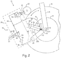
- FIG. 2 is a schematic diagram of ground propulsion assembly 10 from FIG. 1A .
- ground assembly 10 is shown in the engaged position.
- transmission 18 can be a hydrostatic transmission.
- transmission 18 can further include output shaft 34 of motor 32, hydraulic pump 36 with first swash plate 38, hydraulic motor 40 with output shaft 42 and second swash plate 46, and fluid line 48.
- Transmission 18 can also include inlet line 54, reservoir 56, filter 58, and drain 62.
- Hydraulic pump 36 can be disposed within housing 28 of transmission 18 and can be mechanically connected to and powered by output shaft 34 of motor 32. Hydraulic pump 36 can be a pressure compensated variable-displacement pump that uses first swash plate 38 to maintain a pressure output. Hydraulic motor 40 can also be disposed within housing 28 of transmission 18 and can be fluidically connected to hydraulic pump 36 by fluid line 48. Output shaft 42 of hydraulic motor 40 can extend through housing 28 of transmission 18 to mechanically connect with and provide power to drive element 22. Hydraulic motor 40 can be a variable-displacement hydraulic piston motor as shown in FIG. 2 . Second swash plate 46 controls the speed and rotational direction of hydraulic motor 40.
- hydraulic motor 40 can be a variable-displacement hydraulic motor, hydraulic motor 40 can be actuated in both a forward or reverse direction to move drive element 22 in a forward or reverse direction (i.e., clockwise or counterclockwise).
- hydraulic pump 36 can pump hydraulic fluid across hydraulic motor 40 via fluid line 48 to actuate hydraulic motor 40 in a forward direction or a reverse direction depending on the orientation of second swash plate 46. Hydraulic motor 40 then rotates drive element 22 which in turn rotates tire 16 and wheel 14 in the opposite direction of hydraulic motor 40 and drive element 22. While hydraulic motor 40 can operate in both forward and reverse directions, motor 32 and hydraulic pump 36 need only provide output in one direction. Though not shown in FIG.
- rotational reduction means can be mechanically connected between output shaft 42 of hydraulic motor 40 and drive element 22 so as to adjust the rotational speed at which hydraulic motor 40 turns drive element 22.
- the rotational reduction means can be selected from a group of components comprising belts, pulleys, chains, and gears.
- Reservoir 56 can be disposed within housing 28 of transmission 18 and can be fluidically connected to hydraulic pump 36 by inlet line 54 to provide hydraulic fluid to hydraulic pump 36.
- Filter 58 can be fluidically connected on inlet line 54 between hydraulic pump 36 and reservoir 56 to help prevent debris from flowing into hydraulic pump 36 and the fluid circuit between hydraulic pump 36 and hydraulic motor 40.
- Drain 62 can be connected between reservoir 56 and hydraulic motor 40 to direct hydraulic fluid exiting hydraulic motor 40 back to reservoir 56.
- actuator 26 can be configured as a hydraulic ram piston. Actuator 26 extends between first end 68 and second end 70. Along with being a hydraulic ram piston, actuator 26 can be a single-acting cylinder that includes cylindrical tube 72 with inlet 74, piston 75, and piston rod 76. Hose 78 (or another suitable hydraulic connection) extends between transmission 18 and actuator 26 and fluidically connects actuator 26 to transmission 18.
- cylindrical tube 72 is connected to housing 28 of transmission 18.
- Piston 75 is disposed inside cylindrical tube 72, and piston rod 76 extends from piston 75 and at least partially out of cylindrical tube 72.
- piston rod 76 is connected to mounting bar 20 opposite piston 75.
- spring 24 can be disposed around and encircling piston rod 76 and operatively connected between mounting bar 20 and cylindrical tube 72 of actuator 26, with spring 24 exerting a compressive force against mounting bar 20 and cylindrical tube 72.
- spring 24 could be a torsion spring, leaf spring, or a pneumatic spring, and could be arranged in alternate positions on actuator 26 that allow spring 24 to exert a compressive force on or within actuator 26. As shown in FIG.
- inlet 74 is formed in cylindrical tube 72 and hose 78 can be connected between inlet 74 and fluid line 48.
- Hose 78 fluidically connects actuator 26 to the fluid circuit between hydraulic pump 36 and hydraulic motor 40 such that actuator 26 receives hydraulic fluid from hydraulic pump 36 and is pressurized by hydraulic pump 36 during operation.
- motor 32 is activated and drives hydraulic pump 36.
- Hydraulic pump 36 forces pressurized hydraulic fluid across hose 78, through inlet 74, and into cylindrical tube 72.
- piston 75 is pushed towards first end 68 of actuator 26.
- piston 75 pulls piston rod 76 with it towards first end 68 thereby decreasing an overall length of actuator 26.
- actuator 26 compresses spring 24 and causes transmission 18 and drive element 22 to pivot on pivot joint 30 towards wheel 14 and tire 16 such that drive element 22 engages tire 16 and transfers torque to wheel 14.
- hydraulic pump 36 stops and ceases to apply pressure to the hydraulic fluid in actuator 26.
- ground propulsion assembly 10 can be varied and modified without departing the scope of the invention.
- FIGS. 3 and 4 will be discussed concurrently.
- FIGS. 3 is a side view of another example of ground propulsion assembly 10.
- FIG. 4 is a side view of yet another example of ground propulsion assembly 10.
- drive element 22 can be a first gear configured to engage second gear 80 that is mounted coaxial with and rotationally coupled to wheel 14.
- Drive element 22 and second gear 80 can be gears with teeth that mesh, or they can be friction gears that rely on the friction between their two circumferential faces to transfer torque.
- transmission 18 and actuator 24 can function as described above with reference to FIGS. 1A-2 .
- transmission 18 rotates drive element 22 which rotates second gear 80.
- second gear 80 is mounted coaxial with wheel 14, wheel 14 rotates as drive element 22 rotates second gear 80.
- drive element 22 can be a first pulley, and second pulley 82 is mounted coaxial with and rotationally coupled to wheel 14.
- Belt 84 is disposed around drive element 22 and second pulley 82.
- Spring 24 can be a tension spring that pulls transmission 18 and actuator 26 towards wheel 14 and second pulley 82 to a disengagement position such that belt 84 is too slack to transfer torque between drive element 22 and second pulley 82 when electrical motor 32 is deactivated.
- actuator 26 During operation of transmission 18 and electrical motor 32, actuator 26 becomes pressurized and exerts a compressive force that counteracts spring 24 and pushes transmission 18 and drive element 22 away from wheel 14 and second pulley 82, and pushes drive element 22 against belt 84 such that belt 84 is taut and able to transfer torque between drive element 22 and second pulley 82. Because second pulley 82 is mounted coaxial with wheel 14, wheel 14 rotates as drive element 22 rotates second pulley 82.
- Ground propulsion assembly 10 of the present invention can provide numerous advantages and benefits. Some examples of those advantages and benefits are as follows.
- Ground propulsion assembly 10 provides transmission 18, actuator 24, and spring 24, which are configured to function together as a passive, fail-safe coupling mechanism between drive element 22 and wheel 14. Because both actuator 24 and drive element 22 are hydraulically coupled to transmission 18 and are activated and deactivated simultaneously when motor 32 of transmission 18 is activated and deactivated, spring 24 is generally able to passively push drive element 22 out of engagement with wheel 14 whenever transmission 18 and drive element 22 are intentionally deactivated or are deactivated as a result of some kind of unintentional failure.
- ground propulsion assembly 10 minimizes that risk of transmission 18 failing and drive element 22 being stuck in the engaged position where the speeds encountered by wheel 14 during take-off or landing would destroy transmission 18 and possibly create a flying debris hazard. Furthermore, ground propulsion assembly 10 does not utilize expensive power electronics and is relatively simple compared to prior art assemblies that use complex electro-mechanical clutches.
- actuator 26 could also be an electro-mechanical actuator, such as a DC brush motor connected to a ball screw.
- Motor 32 can be an AC motor.
- AC power a rectifier could be utilized to create DC power, which would be directly connected to the brushed dc motor, causing it to produce torque, which would pass through the ball screw, producing force to counteract the disengagement spring.
- actuator 26 can be an induction motor which would use AC power in circuit with motor 32.
- both embodiments of actuator 26 would passively disengage or engage drive element 22, much the same way as a hydraulic ram would, when connected to the hydrostatic transmission.
- many modifications may be made to adapt a particular situation or material to the teachings of the invention without departing from the essential scope thereof. Therefore, it is intended that the invention not be limited to the particular embodiment(s) disclosed, but that the invention will include all embodiments falling within the scope of the appended claims.
Landscapes
- Engineering & Computer Science (AREA)
- Mechanical Engineering (AREA)
- Aviation & Aerospace Engineering (AREA)
- Hydraulic Clutches, Magnetic Clutches, Fluid Clutches, And Fluid Joints (AREA)
- Arrangement And Driving Of Transmission Devices (AREA)
Claims (10)
- Bodenantriebsbaugruppe (10) für ein Luftfahrzeug, wobei die Baugruppe Folgendes umfasst:eine Achse (12);ein Rad (14), das drehbar mit der Achse (12) verbunden ist;ein Getriebe (18), umfassend:ein Gehäuse (28), das in der Nähe der Achse (12) montiert ist; undein Antriebselement (22), das zumindest teilweise außerhalb des Gehäuses (28) angeordnet und mit einer Leistungsaufnahme wirkverbunden ist;eine Befestigungsstange (20), die sich zwischen der Achse (12) und dem Getriebe (18) erstreckt; undeine Ausrückfeder (24), die zwischen dem Getriebe (18) und der Achse (12) angeordnet ist, wobei die Ausrückfeder (24) konfiguriert ist, um das Antriebselement (22) aus einem Eingriff mit dem Rad (14) zu drängen; undeinen Aktor (26), der zwischen dem Getriebe (18) und der Achse (12) wirkverbunden ist, wobei der Aktor (26) konfiguriert ist, um selektiv eine Kraft zu erzeugen, die der Ausrückfeder (24) entgegengesetzt ist, sodass sich das Antriebselement (22) in Bezug auf das Rad (14) bewegt und operativ in das Rad (14) eingreift, um ein Drehmoment auf das Rad (14) zu übertragen,dadurch gekennzeichnet, dassdas erste Ende (20A) der Befestigungsstange (20) starr mit der Achse (12) verbunden ist und das Gehäuse (28) des Getriebes (18) schwenkbar mit dem zweiten Ende (20B) der Befestigungsstange (20) verbunden ist;wobei das Antriebselement (22) ein Reibrad ist, das konfiguriert ist, um direkt in einen Reifen (16) einzugreifen, der um das Rad (14) angeordnet ist.
- Baugruppe nach Anspruch 1, wobei das Antriebselement (22) und das Getriebe (18) konfiguriert sind, um zu dem Rad (14) zu schwenken.
- Baugruppe nach einem der vorhergehenden Ansprüche, wobei das Getriebe ein hydrostatisches Getriebe ist, ferner umfassend:einen Elektromotor (32);eine druckkompensierte Pumpe (36), die mit dem Elektromotor (32) verbunden ist; undeinen Hydraulikmotor (40) mit variabler Verdrängung, der fluidisch mit der druckkompensierten Pumpe (36) verbunden ist.
- Baugruppe nach Anspruch 3, wobei das Antriebselement (22) mit einer Ausgangswelle (34) des Hydraulikmotors (40) mit variabler Verdrängung verbunden ist.
- Baugruppe nach Anspruch 4, wobei der Aktor (26) ein hydraulischer Stößelkolben ist, der sich zwischen dem Getriebe (18) und der Achse (12) erstreckt und fluidisch mit der druckkompensierten Pumpe (36) verbunden ist, und wobei die druckkompensierte Pumpe (36) den hydraulischen Stößelkolben betätigt, um selektiv eine Kraft zu erzeugen, die der Ausrückfeder (24) entgegengesetzt ist, sodass sich das Getriebe (18) dreht und das Antriebselement (22) operativ in das Rad (14) eingreift, um ein Drehmoment auf das Rad (14) zu übertragen.
- Baugruppe nach Anspruch 5, wobei der hydraulische Stößelkolben ein erstes Ende (68), das mit dem Gehäuse des Getriebes (18) verbunden ist und ein zweites Ende (70) aufweist, das mit der Befestigungsstange (20) verbunden ist.
- Baugruppe nach Anspruch 6, wobei der hydraulische Stößelkolben Folgendes umfasst:ein zylindrisches Rohr (72), das mit dem Gehäuse des Getriebes (18) verbunden ist;einen Kolben (75), der in dem zylindrischen Rohr (72) angeordnet ist; undeine Kolbenstange (76), die sich von dem Kolben (75) und zumindest teilweise aus dem zylindrischen Rohr (75) erstreckt, wobei die Kolbenstange (76) mit der Befestigungsstange (20) gegenüber dem Kolben (75) verbunden ist.
- Baugruppe nach Anspruch 7, wobei die Ausrückfeder (24) um die Kolbenstange (76) angeordnet und zwischen der Befestigungsstange (20) und dem zylindrischen Rohr (72) des hydraulischen Stößelkolbens wirkverbunden ist.
- Verfahren zum Betreiben einer Bodenantriebsbaugruppe (10) für ein Luftfahrzeug, wobei das Verfahren Folgendes umfasst:Versorgen eines Elektromotors (32), der mit einem Gehäuse (28) eines Hydraulikgetriebes (18) verbunden ist, mit Strom, wobei das Gehäuse (28) schwenkbar an einem zweiten Ende (20B) einer Befestigungsstange (20) montiert ist, wobei ein erstes Ende (20A) der Befestigungsstange (20) starr mit einer Radachse (12) verbunden ist, wobei das erste Ende (20A) der Befestigungsstange (20) dem zweiten Ende (20B) der Befestigungsstange (20) gegenüberliegt, und wobei sich die Befestigungsstange (20) zwischen der Radachse (12) und dem Getriebe (18) erstreckt;Unter-Druck-Setzen einer Hydraulikleitung in dem Gehäuse, indem der Elektromotor (32) mit einer Hydraulikpumpe (36) wirkverbunden ist;Drehen eines Antriebselements (22), das mit einem Ausgang eines Hydraulikmotors (40) verbunden ist, indem der Hydraulikmotor (40) fluidisch mit der Hydraulikleitung verbunden ist, die durch die Hydraulikpumpe (36) unter Druck gesetzt wird;Unter-Druck-Setzen eines Aktors (26), wobei der Aktor (26) zwischen dem Hydraulikgetriebe (18) und der Achse (12) wirkverbunden und fluidisch mit der Hydraulikleitung verbunden ist, die durch die Hydraulikpumpe (36) unter Druck gesetzt wird, sodass der Aktor (26) eine Kraft erzeugt, die einer Ausrückfeder (24) entgegengesetzt ist, wobei die Ausrückfeder (24) zwischen dem Hydraulikgetriebe (18) und der Achse (12) angeordnet und konfiguriert ist, um das Hydraulikgetriebe (18) aus einem Eingriff mit einem Rad (14) zu drängen, das mit der Achse (12) verbunden ist, sodass sich das Hydraulikgetriebe (18) in Bezug auf das Rad (14) bewegt und das Antriebselement (22) operativ in das Rad (14) eingreift, um ein Drehmoment auf das Rad (14) zu übertragen;wobei das Antriebselement (22) ein Reibrad ist, das konfiguriert ist, um direkt in einen Reifen (16) einzugreifen, der um das Rad (14) angeordnet ist.
- Verfahren nach Anspruch 9, wobei das Verfahren ferner Folgendes umfasst:
operatives Lösen des Antriebselements (22) von dem Rad (14), indem die Stromversorgung des Elektromotors (32) unterbrochen wird, wodurch das Unter-Druck-Setzen der Hydraulikleitung und des Aktors (26) durch die Hydraulikpumpe (36) gestoppt wird, wodurch es der Ausrückfeder (24) ermöglicht wird, das Hydraulikgetriebe (18) und das Antriebselement (22) aus einem Eingriff mit dem Rad (14) zu drängen.
Applications Claiming Priority (2)
| Application Number | Priority Date | Filing Date | Title |
|---|---|---|---|
| US201361888760P | 2013-10-09 | 2013-10-09 | |
| US14/182,174 US9422053B2 (en) | 2013-10-09 | 2014-02-17 | Passive fail safe coupling mechanism |
Publications (3)
| Publication Number | Publication Date |
|---|---|
| EP2860103A1 EP2860103A1 (de) | 2015-04-15 |
| EP2860103B1 EP2860103B1 (de) | 2017-12-06 |
| EP2860103B2 true EP2860103B2 (de) | 2021-04-28 |
Family
ID=51300643
Family Applications (1)
| Application Number | Title | Priority Date | Filing Date |
|---|---|---|---|
| EP14180617.4A Active EP2860103B2 (de) | 2013-10-09 | 2014-08-12 | Passiver ausfallsicherer Kupplungsmechanismus |
Country Status (2)
| Country | Link |
|---|---|
| US (1) | US9422053B2 (de) |
| EP (1) | EP2860103B2 (de) |
Families Citing this family (9)
| Publication number | Priority date | Publication date | Assignee | Title |
|---|---|---|---|---|
| GB2518604A (en) | 2013-09-18 | 2015-04-01 | Airbus Operations Ltd | Drive system for aircraft landing gear |
| GB2528966A (en) | 2014-08-07 | 2016-02-10 | Airbus Operations Ltd | Landing gear drive system |
| FR3031963B1 (fr) * | 2015-01-23 | 2020-02-28 | Safran Landing Systems | Procede d'entrainement en rotation d'une roue d'aeronef. |
| FR3031960B1 (fr) * | 2015-01-23 | 2017-02-10 | Messier Bugatti Dowty | Procede d'entrainement en rotation d'une roue d'aeronef. |
| CN106143876B (zh) * | 2015-04-24 | 2023-11-24 | 空客(北京)工程技术中心有限公司 | 顶推装置、活动机构和飞行器 |
| US9771149B2 (en) * | 2015-10-30 | 2017-09-26 | Honeywell International Inc. | Gate departure system for aircraft |
| FR3082825B1 (fr) * | 2018-06-26 | 2020-09-04 | Safran Landing Systems | Mecanisme de verrouillage d’actionneur de roue |
| US11148789B2 (en) * | 2019-06-14 | 2021-10-19 | The Boeing Company | Taxiing system for an aircraft |
| US11407502B2 (en) * | 2020-02-24 | 2022-08-09 | Safran Landing Systems Canada Inc. | Taxi drive system for aircraft |
Citations (5)
| Publication number | Priority date | Publication date | Assignee | Title |
|---|---|---|---|---|
| WO2011023505A2 (en) † | 2009-08-28 | 2011-03-03 | Airbus Operations Limited | Aircraft landing gear |
| US20120228921A1 (en) † | 2009-12-17 | 2012-09-13 | Michelin Recherche Et Technique S.A. | System for electric motorization of a wheel |
| US20130026284A1 (en) † | 2011-07-27 | 2013-01-31 | Honeywell International Inc. | Aircraft taxi system including drive chain |
| US20130200210A1 (en) † | 2010-04-28 | 2013-08-08 | L-3 Communications Magnet-Motor Gmbh | Drive unit for aircraft running gear |
| WO2014023941A1 (en) † | 2012-08-08 | 2014-02-13 | Airbus Operations Limited | Landing gear drive systems |
Family Cites Families (16)
| Publication number | Priority date | Publication date | Assignee | Title |
|---|---|---|---|---|
| US2399218A (en) | 1943-09-07 | 1946-04-30 | Robert A Felburg | Aircraft landing gear |
| US2507440A (en) | 1946-05-03 | 1950-05-09 | William D Hanson | Power-driven airplane landing gear |
| FR1017435A (fr) | 1950-05-11 | 1952-12-10 | Soc Et Propulsion Par Reaction | Lanceur de roues d'avion |
| US2920845A (en) * | 1955-07-22 | 1960-01-12 | Shepherd Machinery Co | Airplane moving device |
| US3005510A (en) * | 1959-03-09 | 1961-10-24 | Delbert L Phillips | Auxiliary drive unit for vehicles |
| GB961522A (en) | 1963-01-09 | 1964-06-24 | Rolls Royce | Bearing assembly |
| US3762670A (en) | 1971-12-16 | 1973-10-02 | Curtiss Wright Corp | Landing gear wheel drive system for aircraft |
| FR2518650B1 (fr) | 1981-12-22 | 1986-05-30 | Snecma | Dispositif de pilotage des jeux d'un palier inter-arbres de turbomachine multi-corps |
| DE10330805B4 (de) * | 2003-07-08 | 2015-07-30 | Liebherr-Aerospace Lindenberg Gmbh | Luftfahrzeug-Fahrwerksbetätigung |
| US7553248B2 (en) | 2005-09-21 | 2009-06-30 | Exmark Manufacturing Company, Incorporated | Belt drive system incorporating fixed brake member |
| FR2939764B1 (fr) * | 2008-12-16 | 2011-10-21 | Airbus | Train d'atterrissage d'aeronef avec motorisation et transmission |
| FR2954234B1 (fr) | 2009-12-17 | 2012-03-02 | Michelin Soc Tech | Systeme de motorisation d'une roue associee a une suspension |
| US8403257B2 (en) | 2010-12-03 | 2013-03-26 | Bae Systems Controls Inc. | Hydraulic ground propulsion system |
| ES1076258Y (es) | 2011-08-04 | 2012-05-22 | Torres Angel Bartolome | Dispositivo de apoyo al tren de aterrizaje |
| JP5941641B2 (ja) * | 2011-09-15 | 2016-06-29 | 住友精密工業株式会社 | 航空機の脚揚降装置 |
| GB201214198D0 (en) * | 2012-08-08 | 2012-09-19 | Airbus Uk Ltd | Landing gear drive system |
-
2014
- 2014-02-17 US US14/182,174 patent/US9422053B2/en active Active
- 2014-08-12 EP EP14180617.4A patent/EP2860103B2/de active Active
Patent Citations (5)
| Publication number | Priority date | Publication date | Assignee | Title |
|---|---|---|---|---|
| WO2011023505A2 (en) † | 2009-08-28 | 2011-03-03 | Airbus Operations Limited | Aircraft landing gear |
| US20120228921A1 (en) † | 2009-12-17 | 2012-09-13 | Michelin Recherche Et Technique S.A. | System for electric motorization of a wheel |
| US20130200210A1 (en) † | 2010-04-28 | 2013-08-08 | L-3 Communications Magnet-Motor Gmbh | Drive unit for aircraft running gear |
| US20130026284A1 (en) † | 2011-07-27 | 2013-01-31 | Honeywell International Inc. | Aircraft taxi system including drive chain |
| WO2014023941A1 (en) † | 2012-08-08 | 2014-02-13 | Airbus Operations Limited | Landing gear drive systems |
Non-Patent Citations (1)
| Title |
|---|
| "Engineering Essentials: Cylinders", HYDRAULICS AND PNEUMATICS, 1 January 2012 (2012-01-01) † |
Also Published As
| Publication number | Publication date |
|---|---|
| EP2860103B1 (de) | 2017-12-06 |
| US9422053B2 (en) | 2016-08-23 |
| EP2860103A1 (de) | 2015-04-15 |
| US20150097077A1 (en) | 2015-04-09 |
Similar Documents
| Publication | Publication Date | Title |
|---|---|---|
| EP2860103B2 (de) | Passiver ausfallsicherer Kupplungsmechanismus | |
| CN105555662B (zh) | 用于起落架的驱动系统 | |
| US8196855B2 (en) | Helicopter auxiliary anti-torque system | |
| CN104309798B (zh) | 用于飞行器的控制表面的驱动系统 | |
| US8752790B2 (en) | Aircraft landing gear steering system | |
| EP2020379B1 (de) | Fahrwerkanordnung | |
| CN104822590B (zh) | 特别地用于航空器轮子的轮子机动化系统 | |
| EP3116779B1 (de) | Fahrwerksantriebssystem und -verfahren | |
| US8360360B2 (en) | Motorized undercarriage for aircraft | |
| KR20200029053A (ko) | 착륙 장치 구동 시스템 | |
| EP2749494A2 (de) | Fahrwerkradantriebssystem | |
| US8177160B2 (en) | Clutch arrangement | |
| CN104235305A (zh) | 具有离合器套环驱动器机构的差速器组件 | |
| US9221336B1 (en) | Integral power distribution assembly for engine | |
| CN110386247B (zh) | 具有可转向底部的飞行器起落架和简化的转向设备 | |
| GB2274320A (en) | An electromagnetic clutch driven steerable drive axle for a four wheel drive vehicle | |
| EP2117900A1 (de) | Antriebsanordnung für ein regeneratives antriebssystem | |
| US9073530B2 (en) | Systems and methods for reflected inertia parking brake | |
| SE1050176A1 (sv) | Containerlyftok med kollisionsskyddad drivning av teleskoprörelse hos containerlyftokets balkar | |
| EP3116777A1 (de) | Fahrwerksantriebssystem und -verfahren | |
| CN103982615B (zh) | 一种能源驱动转换方法 | |
| EP2765061A1 (de) | Hydraulisches Pumpensystem eines hydraulischen Notservolenkung | |
| CN103994191A (zh) | 一种能源驱动转换机构 |
Legal Events
| Date | Code | Title | Description |
|---|---|---|---|
| PUAI | Public reference made under article 153(3) epc to a published international application that has entered the european phase |
Free format text: ORIGINAL CODE: 0009012 |
|
| 17P | Request for examination filed |
Effective date: 20140812 |
|
| AK | Designated contracting states |
Kind code of ref document: A1 Designated state(s): AL AT BE BG CH CY CZ DE DK EE ES FI FR GB GR HR HU IE IS IT LI LT LU LV MC MK MT NL NO PL PT RO RS SE SI SK SM TR |
|
| AX | Request for extension of the european patent |
Extension state: BA ME |
|
| R17P | Request for examination filed (corrected) |
Effective date: 20150923 |
|
| RBV | Designated contracting states (corrected) |
Designated state(s): AL AT BE BG CH CY CZ DE DK EE ES FI FR GB GR HR HU IE IS IT LI LT LU LV MC MK MT NL NO PL PT RO RS SE SI SK SM TR |
|
| RIC1 | Information provided on ipc code assigned before grant |
Ipc: B64C 25/40 20060101AFI20170511BHEP |
|
| GRAP | Despatch of communication of intention to grant a patent |
Free format text: ORIGINAL CODE: EPIDOSNIGR1 |
|
| STAA | Information on the status of an ep patent application or granted ep patent |
Free format text: STATUS: GRANT OF PATENT IS INTENDED |
|
| INTG | Intention to grant announced |
Effective date: 20170626 |
|
| GRAS | Grant fee paid |
Free format text: ORIGINAL CODE: EPIDOSNIGR3 |
|
| GRAA | (expected) grant |
Free format text: ORIGINAL CODE: 0009210 |
|
| STAA | Information on the status of an ep patent application or granted ep patent |
Free format text: STATUS: THE PATENT HAS BEEN GRANTED |
|
| AK | Designated contracting states |
Kind code of ref document: B1 Designated state(s): AL AT BE BG CH CY CZ DE DK EE ES FI FR GB GR HR HU IE IS IT LI LT LU LV MC MK MT NL NO PL PT RO RS SE SI SK SM TR |
|
| REG | Reference to a national code |
Ref country code: GB Ref legal event code: FG4D |
|
| REG | Reference to a national code |
Ref country code: AT Ref legal event code: REF Ref document number: 952135 Country of ref document: AT Kind code of ref document: T Effective date: 20171215 Ref country code: CH Ref legal event code: EP |
|
| REG | Reference to a national code |
Ref country code: IE Ref legal event code: FG4D |
|
| REG | Reference to a national code |
Ref country code: DE Ref legal event code: R096 Ref document number: 602014018105 Country of ref document: DE |
|
| REG | Reference to a national code |
Ref country code: NL Ref legal event code: MP Effective date: 20171206 |
|
| REG | Reference to a national code |
Ref country code: LT Ref legal event code: MG4D |
|
| PG25 | Lapsed in a contracting state [announced via postgrant information from national office to epo] |
Ref country code: FI Free format text: LAPSE BECAUSE OF FAILURE TO SUBMIT A TRANSLATION OF THE DESCRIPTION OR TO PAY THE FEE WITHIN THE PRESCRIBED TIME-LIMIT Effective date: 20171206 Ref country code: SE Free format text: LAPSE BECAUSE OF FAILURE TO SUBMIT A TRANSLATION OF THE DESCRIPTION OR TO PAY THE FEE WITHIN THE PRESCRIBED TIME-LIMIT Effective date: 20171206 Ref country code: NO Free format text: LAPSE BECAUSE OF FAILURE TO SUBMIT A TRANSLATION OF THE DESCRIPTION OR TO PAY THE FEE WITHIN THE PRESCRIBED TIME-LIMIT Effective date: 20180306 Ref country code: ES Free format text: LAPSE BECAUSE OF FAILURE TO SUBMIT A TRANSLATION OF THE DESCRIPTION OR TO PAY THE FEE WITHIN THE PRESCRIBED TIME-LIMIT Effective date: 20171206 Ref country code: LT Free format text: LAPSE BECAUSE OF FAILURE TO SUBMIT A TRANSLATION OF THE DESCRIPTION OR TO PAY THE FEE WITHIN THE PRESCRIBED TIME-LIMIT Effective date: 20171206 |
|
| REG | Reference to a national code |
Ref country code: AT Ref legal event code: MK05 Ref document number: 952135 Country of ref document: AT Kind code of ref document: T Effective date: 20171206 |
|
| PG25 | Lapsed in a contracting state [announced via postgrant information from national office to epo] |
Ref country code: HR Free format text: LAPSE BECAUSE OF FAILURE TO SUBMIT A TRANSLATION OF THE DESCRIPTION OR TO PAY THE FEE WITHIN THE PRESCRIBED TIME-LIMIT Effective date: 20171206 Ref country code: GR Free format text: LAPSE BECAUSE OF FAILURE TO SUBMIT A TRANSLATION OF THE DESCRIPTION OR TO PAY THE FEE WITHIN THE PRESCRIBED TIME-LIMIT Effective date: 20180307 Ref country code: LV Free format text: LAPSE BECAUSE OF FAILURE TO SUBMIT A TRANSLATION OF THE DESCRIPTION OR TO PAY THE FEE WITHIN THE PRESCRIBED TIME-LIMIT Effective date: 20171206 Ref country code: BG Free format text: LAPSE BECAUSE OF FAILURE TO SUBMIT A TRANSLATION OF THE DESCRIPTION OR TO PAY THE FEE WITHIN THE PRESCRIBED TIME-LIMIT Effective date: 20180306 Ref country code: RS Free format text: LAPSE BECAUSE OF FAILURE TO SUBMIT A TRANSLATION OF THE DESCRIPTION OR TO PAY THE FEE WITHIN THE PRESCRIBED TIME-LIMIT Effective date: 20171206 |
|
| PG25 | Lapsed in a contracting state [announced via postgrant information from national office to epo] |
Ref country code: NL Free format text: LAPSE BECAUSE OF FAILURE TO SUBMIT A TRANSLATION OF THE DESCRIPTION OR TO PAY THE FEE WITHIN THE PRESCRIBED TIME-LIMIT Effective date: 20171206 |
|
| REG | Reference to a national code |
Ref country code: FR Ref legal event code: PLFP Year of fee payment: 5 |
|
| PG25 | Lapsed in a contracting state [announced via postgrant information from national office to epo] |
Ref country code: EE Free format text: LAPSE BECAUSE OF FAILURE TO SUBMIT A TRANSLATION OF THE DESCRIPTION OR TO PAY THE FEE WITHIN THE PRESCRIBED TIME-LIMIT Effective date: 20171206 Ref country code: CZ Free format text: LAPSE BECAUSE OF FAILURE TO SUBMIT A TRANSLATION OF THE DESCRIPTION OR TO PAY THE FEE WITHIN THE PRESCRIBED TIME-LIMIT Effective date: 20171206 Ref country code: SK Free format text: LAPSE BECAUSE OF FAILURE TO SUBMIT A TRANSLATION OF THE DESCRIPTION OR TO PAY THE FEE WITHIN THE PRESCRIBED TIME-LIMIT Effective date: 20171206 |
|
| PG25 | Lapsed in a contracting state [announced via postgrant information from national office to epo] |
Ref country code: AT Free format text: LAPSE BECAUSE OF FAILURE TO SUBMIT A TRANSLATION OF THE DESCRIPTION OR TO PAY THE FEE WITHIN THE PRESCRIBED TIME-LIMIT Effective date: 20171206 Ref country code: SM Free format text: LAPSE BECAUSE OF FAILURE TO SUBMIT A TRANSLATION OF THE DESCRIPTION OR TO PAY THE FEE WITHIN THE PRESCRIBED TIME-LIMIT Effective date: 20171206 Ref country code: IT Free format text: LAPSE BECAUSE OF FAILURE TO SUBMIT A TRANSLATION OF THE DESCRIPTION OR TO PAY THE FEE WITHIN THE PRESCRIBED TIME-LIMIT Effective date: 20171206 Ref country code: RO Free format text: LAPSE BECAUSE OF FAILURE TO SUBMIT A TRANSLATION OF THE DESCRIPTION OR TO PAY THE FEE WITHIN THE PRESCRIBED TIME-LIMIT Effective date: 20171206 Ref country code: PL Free format text: LAPSE BECAUSE OF FAILURE TO SUBMIT A TRANSLATION OF THE DESCRIPTION OR TO PAY THE FEE WITHIN THE PRESCRIBED TIME-LIMIT Effective date: 20171206 |
|
| REG | Reference to a national code |
Ref country code: DE Ref legal event code: R026 Ref document number: 602014018105 Country of ref document: DE |
|
| PLBI | Opposition filed |
Free format text: ORIGINAL CODE: 0009260 |
|
| PLAX | Notice of opposition and request to file observation + time limit sent |
Free format text: ORIGINAL CODE: EPIDOSNOBS2 |
|
| 26 | Opposition filed |
Opponent name: ABITZ & PARTNER PATENTANWAELTE MBB Effective date: 20180905 |
|
| PG25 | Lapsed in a contracting state [announced via postgrant information from national office to epo] |
Ref country code: DK Free format text: LAPSE BECAUSE OF FAILURE TO SUBMIT A TRANSLATION OF THE DESCRIPTION OR TO PAY THE FEE WITHIN THE PRESCRIBED TIME-LIMIT Effective date: 20171206 Ref country code: SI Free format text: LAPSE BECAUSE OF FAILURE TO SUBMIT A TRANSLATION OF THE DESCRIPTION OR TO PAY THE FEE WITHIN THE PRESCRIBED TIME-LIMIT Effective date: 20171206 |
|
| PLBB | Reply of patent proprietor to notice(s) of opposition received |
Free format text: ORIGINAL CODE: EPIDOSNOBS3 |
|
| PG25 | Lapsed in a contracting state [announced via postgrant information from national office to epo] |
Ref country code: MC Free format text: LAPSE BECAUSE OF FAILURE TO SUBMIT A TRANSLATION OF THE DESCRIPTION OR TO PAY THE FEE WITHIN THE PRESCRIBED TIME-LIMIT Effective date: 20171206 |
|
| REG | Reference to a national code |
Ref country code: CH Ref legal event code: PL |
|
| PG25 | Lapsed in a contracting state [announced via postgrant information from national office to epo] |
Ref country code: LU Free format text: LAPSE BECAUSE OF NON-PAYMENT OF DUE FEES Effective date: 20180812 Ref country code: CH Free format text: LAPSE BECAUSE OF NON-PAYMENT OF DUE FEES Effective date: 20180831 Ref country code: LI Free format text: LAPSE BECAUSE OF NON-PAYMENT OF DUE FEES Effective date: 20180831 |
|
| REG | Reference to a national code |
Ref country code: BE Ref legal event code: MM Effective date: 20180831 |
|
| REG | Reference to a national code |
Ref country code: IE Ref legal event code: MM4A |
|
| PG25 | Lapsed in a contracting state [announced via postgrant information from national office to epo] |
Ref country code: IE Free format text: LAPSE BECAUSE OF NON-PAYMENT OF DUE FEES Effective date: 20180812 |
|
| PG25 | Lapsed in a contracting state [announced via postgrant information from national office to epo] |
Ref country code: BE Free format text: LAPSE BECAUSE OF NON-PAYMENT OF DUE FEES Effective date: 20180831 |
|
| PG25 | Lapsed in a contracting state [announced via postgrant information from national office to epo] |
Ref country code: MT Free format text: LAPSE BECAUSE OF NON-PAYMENT OF DUE FEES Effective date: 20180812 |
|
| PLAY | Examination report in opposition despatched + time limit |
Free format text: ORIGINAL CODE: EPIDOSNORE2 |
|
| PG25 | Lapsed in a contracting state [announced via postgrant information from national office to epo] |
Ref country code: TR Free format text: LAPSE BECAUSE OF FAILURE TO SUBMIT A TRANSLATION OF THE DESCRIPTION OR TO PAY THE FEE WITHIN THE PRESCRIBED TIME-LIMIT Effective date: 20171206 |
|
| PLBC | Reply to examination report in opposition received |
Free format text: ORIGINAL CODE: EPIDOSNORE3 |
|
| PG25 | Lapsed in a contracting state [announced via postgrant information from national office to epo] |
Ref country code: HU Free format text: LAPSE BECAUSE OF FAILURE TO SUBMIT A TRANSLATION OF THE DESCRIPTION OR TO PAY THE FEE WITHIN THE PRESCRIBED TIME-LIMIT; INVALID AB INITIO Effective date: 20140812 Ref country code: PT Free format text: LAPSE BECAUSE OF FAILURE TO SUBMIT A TRANSLATION OF THE DESCRIPTION OR TO PAY THE FEE WITHIN THE PRESCRIBED TIME-LIMIT Effective date: 20171206 |
|
| PG25 | Lapsed in a contracting state [announced via postgrant information from national office to epo] |
Ref country code: MK Free format text: LAPSE BECAUSE OF NON-PAYMENT OF DUE FEES Effective date: 20171206 Ref country code: CY Free format text: LAPSE BECAUSE OF FAILURE TO SUBMIT A TRANSLATION OF THE DESCRIPTION OR TO PAY THE FEE WITHIN THE PRESCRIBED TIME-LIMIT Effective date: 20171206 |
|
| PG25 | Lapsed in a contracting state [announced via postgrant information from national office to epo] |
Ref country code: AL Free format text: LAPSE BECAUSE OF FAILURE TO SUBMIT A TRANSLATION OF THE DESCRIPTION OR TO PAY THE FEE WITHIN THE PRESCRIBED TIME-LIMIT Effective date: 20171206 Ref country code: IS Free format text: LAPSE BECAUSE OF FAILURE TO SUBMIT A TRANSLATION OF THE DESCRIPTION OR TO PAY THE FEE WITHIN THE PRESCRIBED TIME-LIMIT Effective date: 20180406 |
|
| PUAH | Patent maintained in amended form |
Free format text: ORIGINAL CODE: 0009272 |
|
| STAA | Information on the status of an ep patent application or granted ep patent |
Free format text: STATUS: PATENT MAINTAINED AS AMENDED |
|
| 27A | Patent maintained in amended form |
Effective date: 20210428 |
|
| AK | Designated contracting states |
Kind code of ref document: B2 Designated state(s): AL AT BE BG CH CY CZ DE DK EE ES FI FR GB GR HR HU IE IS IT LI LT LU LV MC MK MT NL NO PL PT RO RS SE SI SK SM TR |
|
| REG | Reference to a national code |
Ref country code: DE Ref legal event code: R102 Ref document number: 602014018105 Country of ref document: DE |
|
| P01 | Opt-out of the competence of the unified patent court (upc) registered |
Effective date: 20230522 |
|
| PGFP | Annual fee paid to national office [announced via postgrant information from national office to epo] |
Ref country code: DE Payment date: 20250724 Year of fee payment: 12 |
|
| PGFP | Annual fee paid to national office [announced via postgrant information from national office to epo] |
Ref country code: GB Payment date: 20250724 Year of fee payment: 12 |
|
| PGFP | Annual fee paid to national office [announced via postgrant information from national office to epo] |
Ref country code: FR Payment date: 20250725 Year of fee payment: 12 |