EP2860018B1 - Bends in composite panels - Google Patents
Bends in composite panels Download PDFInfo
- Publication number
- EP2860018B1 EP2860018B1 EP14187328.1A EP14187328A EP2860018B1 EP 2860018 B1 EP2860018 B1 EP 2860018B1 EP 14187328 A EP14187328 A EP 14187328A EP 2860018 B1 EP2860018 B1 EP 2860018B1
- Authority
- EP
- European Patent Office
- Prior art keywords
- bend
- slot
- composite panel
- composite
- layer
- Prior art date
- Legal status (The legal status is an assumption and is not a legal conclusion. Google has not performed a legal analysis and makes no representation as to the accuracy of the status listed.)
- Active
Links
- 239000002131 composite material Substances 0.000 title claims description 264
- 238000000034 method Methods 0.000 claims description 63
- 239000000945 filler Substances 0.000 claims description 54
- 238000005452 bending Methods 0.000 claims description 39
- 239000000463 material Substances 0.000 claims description 32
- 239000011152 fibreglass Substances 0.000 claims description 22
- 239000000835 fiber Substances 0.000 claims description 6
- 238000004519 manufacturing process Methods 0.000 description 19
- 230000008569 process Effects 0.000 description 18
- 238000012423 maintenance Methods 0.000 description 8
- 238000010586 diagram Methods 0.000 description 7
- 239000000853 adhesive Substances 0.000 description 6
- 230000001070 adhesive effect Effects 0.000 description 6
- 239000004744 fabric Substances 0.000 description 5
- 239000011347 resin Substances 0.000 description 5
- 229920005989 resin Polymers 0.000 description 5
- 230000010354 integration Effects 0.000 description 4
- 230000004048 modification Effects 0.000 description 3
- 238000012986 modification Methods 0.000 description 3
- 239000004593 Epoxy Substances 0.000 description 2
- 230000008859 change Effects 0.000 description 2
- 239000011159 matrix material Substances 0.000 description 2
- 238000009419 refurbishment Methods 0.000 description 2
- 239000007787 solid Substances 0.000 description 2
- 239000003381 stabilizer Substances 0.000 description 2
- 229920000049 Carbon (fiber) Polymers 0.000 description 1
- 229920000784 Nomex Polymers 0.000 description 1
- 229910000831 Steel Inorganic materials 0.000 description 1
- XAGFODPZIPBFFR-UHFFFAOYSA-N aluminium Chemical compound [Al] XAGFODPZIPBFFR-UHFFFAOYSA-N 0.000 description 1
- 229910052782 aluminium Inorganic materials 0.000 description 1
- 230000015572 biosynthetic process Effects 0.000 description 1
- 239000004917 carbon fiber Substances 0.000 description 1
- 230000015556 catabolic process Effects 0.000 description 1
- 239000003795 chemical substances by application Substances 0.000 description 1
- 238000010276 construction Methods 0.000 description 1
- 230000003247 decreasing effect Effects 0.000 description 1
- 238000006731 degradation reaction Methods 0.000 description 1
- 238000013461 design Methods 0.000 description 1
- 230000007613 environmental effect Effects 0.000 description 1
- 239000011888 foil Substances 0.000 description 1
- 239000000446 fuel Substances 0.000 description 1
- 239000003562 lightweight material Substances 0.000 description 1
- -1 metallic Substances 0.000 description 1
- VNWKTOKETHGBQD-UHFFFAOYSA-N methane Chemical compound C VNWKTOKETHGBQD-UHFFFAOYSA-N 0.000 description 1
- 239000004763 nomex Substances 0.000 description 1
- 230000008520 organization Effects 0.000 description 1
- ISWSIDIOOBJBQZ-UHFFFAOYSA-N phenol group Chemical group C1(=CC=CC=C1)O ISWSIDIOOBJBQZ-UHFFFAOYSA-N 0.000 description 1
- 229920000728 polyester Polymers 0.000 description 1
- 238000012545 processing Methods 0.000 description 1
- 230000002787 reinforcement Effects 0.000 description 1
- 239000012783 reinforcing fiber Substances 0.000 description 1
- 239000012779 reinforcing material Substances 0.000 description 1
- 239000010959 steel Substances 0.000 description 1
- 239000002759 woven fabric Substances 0.000 description 1
Images


Classifications
-
- B—PERFORMING OPERATIONS; TRANSPORTING
- B29—WORKING OF PLASTICS; WORKING OF SUBSTANCES IN A PLASTIC STATE IN GENERAL
- B29C—SHAPING OR JOINING OF PLASTICS; SHAPING OF MATERIAL IN A PLASTIC STATE, NOT OTHERWISE PROVIDED FOR; AFTER-TREATMENT OF THE SHAPED PRODUCTS, e.g. REPAIRING
- B29C53/00—Shaping by bending, folding, twisting, straightening or flattening; Apparatus therefor
- B29C53/02—Bending or folding
- B29C53/04—Bending or folding of plates or sheets
-
- B—PERFORMING OPERATIONS; TRANSPORTING
- B26—HAND CUTTING TOOLS; CUTTING; SEVERING
- B26D—CUTTING; DETAILS COMMON TO MACHINES FOR PERFORATING, PUNCHING, CUTTING-OUT, STAMPING-OUT OR SEVERING
- B26D3/00—Cutting work characterised by the nature of the cut made; Apparatus therefor
- B26D3/06—Grooving involving removal of material from the surface of the work
-
- B—PERFORMING OPERATIONS; TRANSPORTING
- B29—WORKING OF PLASTICS; WORKING OF SUBSTANCES IN A PLASTIC STATE IN GENERAL
- B29C—SHAPING OR JOINING OF PLASTICS; SHAPING OF MATERIAL IN A PLASTIC STATE, NOT OTHERWISE PROVIDED FOR; AFTER-TREATMENT OF THE SHAPED PRODUCTS, e.g. REPAIRING
- B29C53/00—Shaping by bending, folding, twisting, straightening or flattening; Apparatus therefor
- B29C53/02—Bending or folding
- B29C53/04—Bending or folding of plates or sheets
- B29C53/06—Forming folding lines by pressing or scoring
- B29C53/063—Forming folding lines by pressing or scoring combined with folding
-
- B—PERFORMING OPERATIONS; TRANSPORTING
- B29—WORKING OF PLASTICS; WORKING OF SUBSTANCES IN A PLASTIC STATE IN GENERAL
- B29C—SHAPING OR JOINING OF PLASTICS; SHAPING OF MATERIAL IN A PLASTIC STATE, NOT OTHERWISE PROVIDED FOR; AFTER-TREATMENT OF THE SHAPED PRODUCTS, e.g. REPAIRING
- B29C70/00—Shaping composites, i.e. plastics material comprising reinforcements, fillers or preformed parts, e.g. inserts
- B29C70/02—Shaping composites, i.e. plastics material comprising reinforcements, fillers or preformed parts, e.g. inserts comprising combinations of reinforcements, e.g. non-specified reinforcements, fibrous reinforcing inserts and fillers, e.g. particulate fillers, incorporated in matrix material, forming one or more layers and with or without non-reinforced or non-filled layers
-
- B—PERFORMING OPERATIONS; TRANSPORTING
- B29—WORKING OF PLASTICS; WORKING OF SUBSTANCES IN A PLASTIC STATE IN GENERAL
- B29D—PRODUCING PARTICULAR ARTICLES FROM PLASTICS OR FROM SUBSTANCES IN A PLASTIC STATE
- B29D99/00—Subject matter not provided for in other groups of this subclass
- B29D99/001—Producing wall or panel-like structures, e.g. for hulls, fuselages, or buildings
-
- B—PERFORMING OPERATIONS; TRANSPORTING
- B32—LAYERED PRODUCTS
- B32B—LAYERED PRODUCTS, i.e. PRODUCTS BUILT-UP OF STRATA OF FLAT OR NON-FLAT, e.g. CELLULAR OR HONEYCOMB, FORM
- B32B3/00—Layered products comprising a layer with external or internal discontinuities or unevennesses, or a layer of non-planar shape; Layered products comprising a layer having particular features of form
- B32B3/02—Layered products comprising a layer with external or internal discontinuities or unevennesses, or a layer of non-planar shape; Layered products comprising a layer having particular features of form characterised by features of form at particular places, e.g. in edge regions
-
- B—PERFORMING OPERATIONS; TRANSPORTING
- B32—LAYERED PRODUCTS
- B32B—LAYERED PRODUCTS, i.e. PRODUCTS BUILT-UP OF STRATA OF FLAT OR NON-FLAT, e.g. CELLULAR OR HONEYCOMB, FORM
- B32B3/00—Layered products comprising a layer with external or internal discontinuities or unevennesses, or a layer of non-planar shape; Layered products comprising a layer having particular features of form
- B32B3/26—Layered products comprising a layer with external or internal discontinuities or unevennesses, or a layer of non-planar shape; Layered products comprising a layer having particular features of form characterised by a particular shape of the outline of the cross-section of a continuous layer; characterised by a layer with cavities or internal voids ; characterised by an apertured layer
- B32B3/28—Layered products comprising a layer with external or internal discontinuities or unevennesses, or a layer of non-planar shape; Layered products comprising a layer having particular features of form characterised by a particular shape of the outline of the cross-section of a continuous layer; characterised by a layer with cavities or internal voids ; characterised by an apertured layer characterised by a layer comprising a deformed thin sheet, i.e. the layer having its entire thickness deformed out of the plane, e.g. corrugated, crumpled
-
- B—PERFORMING OPERATIONS; TRANSPORTING
- B32—LAYERED PRODUCTS
- B32B—LAYERED PRODUCTS, i.e. PRODUCTS BUILT-UP OF STRATA OF FLAT OR NON-FLAT, e.g. CELLULAR OR HONEYCOMB, FORM
- B32B3/00—Layered products comprising a layer with external or internal discontinuities or unevennesses, or a layer of non-planar shape; Layered products comprising a layer having particular features of form
- B32B3/26—Layered products comprising a layer with external or internal discontinuities or unevennesses, or a layer of non-planar shape; Layered products comprising a layer having particular features of form characterised by a particular shape of the outline of the cross-section of a continuous layer; characterised by a layer with cavities or internal voids ; characterised by an apertured layer
- B32B3/30—Layered products comprising a layer with external or internal discontinuities or unevennesses, or a layer of non-planar shape; Layered products comprising a layer having particular features of form characterised by a particular shape of the outline of the cross-section of a continuous layer; characterised by a layer with cavities or internal voids ; characterised by an apertured layer characterised by a layer formed with recesses or projections, e.g. hollows, grooves, protuberances, ribs
-
- B—PERFORMING OPERATIONS; TRANSPORTING
- B32—LAYERED PRODUCTS
- B32B—LAYERED PRODUCTS, i.e. PRODUCTS BUILT-UP OF STRATA OF FLAT OR NON-FLAT, e.g. CELLULAR OR HONEYCOMB, FORM
- B32B5/00—Layered products characterised by the non- homogeneity or physical structure, i.e. comprising a fibrous, filamentary, particulate or foam layer; Layered products characterised by having a layer differing constitutionally or physically in different parts
- B32B5/22—Layered products characterised by the non- homogeneity or physical structure, i.e. comprising a fibrous, filamentary, particulate or foam layer; Layered products characterised by having a layer differing constitutionally or physically in different parts characterised by the presence of two or more layers which are next to each other and are fibrous, filamentary, formed of particles or foamed
- B32B5/24—Layered products characterised by the non- homogeneity or physical structure, i.e. comprising a fibrous, filamentary, particulate or foam layer; Layered products characterised by having a layer differing constitutionally or physically in different parts characterised by the presence of two or more layers which are next to each other and are fibrous, filamentary, formed of particles or foamed one layer being a fibrous or filamentary layer
- B32B5/26—Layered products characterised by the non- homogeneity or physical structure, i.e. comprising a fibrous, filamentary, particulate or foam layer; Layered products characterised by having a layer differing constitutionally or physically in different parts characterised by the presence of two or more layers which are next to each other and are fibrous, filamentary, formed of particles or foamed one layer being a fibrous or filamentary layer another layer next to it also being fibrous or filamentary
-
- E—FIXED CONSTRUCTIONS
- E04—BUILDING
- E04C—STRUCTURAL ELEMENTS; BUILDING MATERIALS
- E04C2/00—Building elements of relatively thin form for the construction of parts of buildings, e.g. sheet materials, slabs, or panels
-
- E—FIXED CONSTRUCTIONS
- E04—BUILDING
- E04C—STRUCTURAL ELEMENTS; BUILDING MATERIALS
- E04C2/00—Building elements of relatively thin form for the construction of parts of buildings, e.g. sheet materials, slabs, or panels
- E04C2/02—Building elements of relatively thin form for the construction of parts of buildings, e.g. sheet materials, slabs, or panels characterised by specified materials
- E04C2/10—Building elements of relatively thin form for the construction of parts of buildings, e.g. sheet materials, slabs, or panels characterised by specified materials of wood, fibres, chips, vegetable stems, or the like; of plastics; of foamed products
- E04C2/24—Building elements of relatively thin form for the construction of parts of buildings, e.g. sheet materials, slabs, or panels characterised by specified materials of wood, fibres, chips, vegetable stems, or the like; of plastics; of foamed products laminated and composed of materials covered by two or more of groups E04C2/12, E04C2/16, E04C2/20
-
- E—FIXED CONSTRUCTIONS
- E04—BUILDING
- E04C—STRUCTURAL ELEMENTS; BUILDING MATERIALS
- E04C2/00—Building elements of relatively thin form for the construction of parts of buildings, e.g. sheet materials, slabs, or panels
- E04C2/30—Building elements of relatively thin form for the construction of parts of buildings, e.g. sheet materials, slabs, or panels characterised by the shape or structure
- E04C2/34—Building elements of relatively thin form for the construction of parts of buildings, e.g. sheet materials, slabs, or panels characterised by the shape or structure composed of two or more spaced sheet-like parts
- E04C2/36—Building elements of relatively thin form for the construction of parts of buildings, e.g. sheet materials, slabs, or panels characterised by the shape or structure composed of two or more spaced sheet-like parts spaced apart by transversely-placed strip material, e.g. honeycomb panels
- E04C2/365—Building elements of relatively thin form for the construction of parts of buildings, e.g. sheet materials, slabs, or panels characterised by the shape or structure composed of two or more spaced sheet-like parts spaced apart by transversely-placed strip material, e.g. honeycomb panels by honeycomb structures
-
- B—PERFORMING OPERATIONS; TRANSPORTING
- B23—MACHINE TOOLS; METAL-WORKING NOT OTHERWISE PROVIDED FOR
- B23C—MILLING
- B23C3/00—Milling particular work; Special milling operations; Machines therefor
- B23C3/28—Grooving workpieces
- B23C3/34—Milling grooves of other forms, e.g. circumferential
-
- B—PERFORMING OPERATIONS; TRANSPORTING
- B26—HAND CUTTING TOOLS; CUTTING; SEVERING
- B26D—CUTTING; DETAILS COMMON TO MACHINES FOR PERFORATING, PUNCHING, CUTTING-OUT, STAMPING-OUT OR SEVERING
- B26D3/00—Cutting work characterised by the nature of the cut made; Apparatus therefor
- B26D3/06—Grooving involving removal of material from the surface of the work
- B26D3/065—On sheet material
-
- B—PERFORMING OPERATIONS; TRANSPORTING
- B26—HAND CUTTING TOOLS; CUTTING; SEVERING
- B26D—CUTTING; DETAILS COMMON TO MACHINES FOR PERFORATING, PUNCHING, CUTTING-OUT, STAMPING-OUT OR SEVERING
- B26D5/00—Arrangements for operating and controlling machines or devices for cutting, cutting-out, stamping-out, punching, perforating, or severing by means other than cutting
- B26D5/20—Arrangements for operating and controlling machines or devices for cutting, cutting-out, stamping-out, punching, perforating, or severing by means other than cutting with interrelated action between the cutting member and work feed
-
- B—PERFORMING OPERATIONS; TRANSPORTING
- B29—WORKING OF PLASTICS; WORKING OF SUBSTANCES IN A PLASTIC STATE IN GENERAL
- B29C—SHAPING OR JOINING OF PLASTICS; SHAPING OF MATERIAL IN A PLASTIC STATE, NOT OTHERWISE PROVIDED FOR; AFTER-TREATMENT OF THE SHAPED PRODUCTS, e.g. REPAIRING
- B29C2793/00—Shaping techniques involving a cutting or machining operation
- B29C2793/0009—Cutting out
-
- B—PERFORMING OPERATIONS; TRANSPORTING
- B29—WORKING OF PLASTICS; WORKING OF SUBSTANCES IN A PLASTIC STATE IN GENERAL
- B29K—INDEXING SCHEME ASSOCIATED WITH SUBCLASSES B29B, B29C OR B29D, RELATING TO MOULDING MATERIALS OR TO MATERIALS FOR MOULDS, REINFORCEMENTS, FILLERS OR PREFORMED PARTS, e.g. INSERTS
- B29K2105/00—Condition, form or state of moulded material or of the material to be shaped
- B29K2105/06—Condition, form or state of moulded material or of the material to be shaped containing reinforcements, fillers or inserts
-
- B—PERFORMING OPERATIONS; TRANSPORTING
- B29—WORKING OF PLASTICS; WORKING OF SUBSTANCES IN A PLASTIC STATE IN GENERAL
- B29K—INDEXING SCHEME ASSOCIATED WITH SUBCLASSES B29B, B29C OR B29D, RELATING TO MOULDING MATERIALS OR TO MATERIALS FOR MOULDS, REINFORCEMENTS, FILLERS OR PREFORMED PARTS, e.g. INSERTS
- B29K2105/00—Condition, form or state of moulded material or of the material to be shaped
- B29K2105/25—Solid
- B29K2105/253—Preform
- B29K2105/256—Sheets, plates, blanks or films
-
- B—PERFORMING OPERATIONS; TRANSPORTING
- B29—WORKING OF PLASTICS; WORKING OF SUBSTANCES IN A PLASTIC STATE IN GENERAL
- B29L—INDEXING SCHEME ASSOCIATED WITH SUBCLASS B29C, RELATING TO PARTICULAR ARTICLES
- B29L2009/00—Layered products
-
- B—PERFORMING OPERATIONS; TRANSPORTING
- B29—WORKING OF PLASTICS; WORKING OF SUBSTANCES IN A PLASTIC STATE IN GENERAL
- B29L—INDEXING SCHEME ASSOCIATED WITH SUBCLASS B29C, RELATING TO PARTICULAR ARTICLES
- B29L2031/00—Other particular articles
- B29L2031/30—Vehicles, e.g. ships or aircraft, or body parts thereof
- B29L2031/3076—Aircrafts
-
- B—PERFORMING OPERATIONS; TRANSPORTING
- B29—WORKING OF PLASTICS; WORKING OF SUBSTANCES IN A PLASTIC STATE IN GENERAL
- B29L—INDEXING SCHEME ASSOCIATED WITH SUBCLASS B29C, RELATING TO PARTICULAR ARTICLES
- B29L2031/00—Other particular articles
- B29L2031/60—Multitubular or multicompartmented articles, e.g. honeycomb
- B29L2031/608—Honeycomb structures
-
- B—PERFORMING OPERATIONS; TRANSPORTING
- B32—LAYERED PRODUCTS
- B32B—LAYERED PRODUCTS, i.e. PRODUCTS BUILT-UP OF STRATA OF FLAT OR NON-FLAT, e.g. CELLULAR OR HONEYCOMB, FORM
- B32B2260/00—Layered product comprising an impregnated, embedded, or bonded layer wherein the layer comprises an impregnation, embedding, or binder material
- B32B2260/02—Composition of the impregnated, bonded or embedded layer
- B32B2260/021—Fibrous or filamentary layer
- B32B2260/023—Two or more layers
-
- B—PERFORMING OPERATIONS; TRANSPORTING
- B32—LAYERED PRODUCTS
- B32B—LAYERED PRODUCTS, i.e. PRODUCTS BUILT-UP OF STRATA OF FLAT OR NON-FLAT, e.g. CELLULAR OR HONEYCOMB, FORM
- B32B2260/00—Layered product comprising an impregnated, embedded, or bonded layer wherein the layer comprises an impregnation, embedding, or binder material
- B32B2260/04—Impregnation, embedding, or binder material
- B32B2260/046—Synthetic resin
-
- B—PERFORMING OPERATIONS; TRANSPORTING
- B32—LAYERED PRODUCTS
- B32B—LAYERED PRODUCTS, i.e. PRODUCTS BUILT-UP OF STRATA OF FLAT OR NON-FLAT, e.g. CELLULAR OR HONEYCOMB, FORM
- B32B2262/00—Composition or structural features of fibres which form a fibrous or filamentary layer or are present as additives
- B32B2262/10—Inorganic fibres
- B32B2262/101—Glass fibres
-
- B—PERFORMING OPERATIONS; TRANSPORTING
- B32—LAYERED PRODUCTS
- B32B—LAYERED PRODUCTS, i.e. PRODUCTS BUILT-UP OF STRATA OF FLAT OR NON-FLAT, e.g. CELLULAR OR HONEYCOMB, FORM
- B32B2305/00—Condition, form or state of the layers or laminate
- B32B2305/02—Cellular or porous
- B32B2305/024—Honeycomb
-
- B—PERFORMING OPERATIONS; TRANSPORTING
- B32—LAYERED PRODUCTS
- B32B—LAYERED PRODUCTS, i.e. PRODUCTS BUILT-UP OF STRATA OF FLAT OR NON-FLAT, e.g. CELLULAR OR HONEYCOMB, FORM
- B32B2605/00—Vehicles
- B32B2605/18—Aircraft
-
- B—PERFORMING OPERATIONS; TRANSPORTING
- B32—LAYERED PRODUCTS
- B32B—LAYERED PRODUCTS, i.e. PRODUCTS BUILT-UP OF STRATA OF FLAT OR NON-FLAT, e.g. CELLULAR OR HONEYCOMB, FORM
- B32B3/00—Layered products comprising a layer with external or internal discontinuities or unevennesses, or a layer of non-planar shape; Layered products comprising a layer having particular features of form
- B32B3/10—Layered products comprising a layer with external or internal discontinuities or unevennesses, or a layer of non-planar shape; Layered products comprising a layer having particular features of form characterised by a discontinuous layer, i.e. formed of separate pieces of material
- B32B3/12—Layered products comprising a layer with external or internal discontinuities or unevennesses, or a layer of non-planar shape; Layered products comprising a layer having particular features of form characterised by a discontinuous layer, i.e. formed of separate pieces of material characterised by a layer of regularly- arranged cells, e.g. a honeycomb structure
-
- Y—GENERAL TAGGING OF NEW TECHNOLOGICAL DEVELOPMENTS; GENERAL TAGGING OF CROSS-SECTIONAL TECHNOLOGIES SPANNING OVER SEVERAL SECTIONS OF THE IPC; TECHNICAL SUBJECTS COVERED BY FORMER USPC CROSS-REFERENCE ART COLLECTIONS [XRACs] AND DIGESTS
- Y02—TECHNOLOGIES OR APPLICATIONS FOR MITIGATION OR ADAPTATION AGAINST CLIMATE CHANGE
- Y02T—CLIMATE CHANGE MITIGATION TECHNOLOGIES RELATED TO TRANSPORTATION
- Y02T50/00—Aeronautics or air transport
- Y02T50/40—Weight reduction
-
- Y—GENERAL TAGGING OF NEW TECHNOLOGICAL DEVELOPMENTS; GENERAL TAGGING OF CROSS-SECTIONAL TECHNOLOGIES SPANNING OVER SEVERAL SECTIONS OF THE IPC; TECHNICAL SUBJECTS COVERED BY FORMER USPC CROSS-REFERENCE ART COLLECTIONS [XRACs] AND DIGESTS
- Y10—TECHNICAL SUBJECTS COVERED BY FORMER USPC
- Y10T—TECHNICAL SUBJECTS COVERED BY FORMER US CLASSIFICATION
- Y10T156/00—Adhesive bonding and miscellaneous chemical manufacture
- Y10T156/10—Methods of surface bonding and/or assembly therefor
- Y10T156/1002—Methods of surface bonding and/or assembly therefor with permanent bending or reshaping or surface deformation of self sustaining lamina
- Y10T156/1026—Methods of surface bonding and/or assembly therefor with permanent bending or reshaping or surface deformation of self sustaining lamina with slitting or removal of material at reshaping area prior to reshaping
-
- Y—GENERAL TAGGING OF NEW TECHNOLOGICAL DEVELOPMENTS; GENERAL TAGGING OF CROSS-SECTIONAL TECHNOLOGIES SPANNING OVER SEVERAL SECTIONS OF THE IPC; TECHNICAL SUBJECTS COVERED BY FORMER USPC CROSS-REFERENCE ART COLLECTIONS [XRACs] AND DIGESTS
- Y10—TECHNICAL SUBJECTS COVERED BY FORMER USPC
- Y10T—TECHNICAL SUBJECTS COVERED BY FORMER US CLASSIFICATION
- Y10T156/00—Adhesive bonding and miscellaneous chemical manufacture
- Y10T156/10—Methods of surface bonding and/or assembly therefor
- Y10T156/1002—Methods of surface bonding and/or assembly therefor with permanent bending or reshaping or surface deformation of self sustaining lamina
- Y10T156/1043—Subsequent to assembly
- Y10T156/1044—Subsequent to assembly of parallel stacked sheets only
-
- Y—GENERAL TAGGING OF NEW TECHNOLOGICAL DEVELOPMENTS; GENERAL TAGGING OF CROSS-SECTIONAL TECHNOLOGIES SPANNING OVER SEVERAL SECTIONS OF THE IPC; TECHNICAL SUBJECTS COVERED BY FORMER USPC CROSS-REFERENCE ART COLLECTIONS [XRACs] AND DIGESTS
- Y10—TECHNICAL SUBJECTS COVERED BY FORMER USPC
- Y10T—TECHNICAL SUBJECTS COVERED BY FORMER US CLASSIFICATION
- Y10T29/00—Metal working
- Y10T29/49—Method of mechanical manufacture
- Y10T29/49801—Shaping fiber or fibered material
-
- Y—GENERAL TAGGING OF NEW TECHNOLOGICAL DEVELOPMENTS; GENERAL TAGGING OF CROSS-SECTIONAL TECHNOLOGIES SPANNING OVER SEVERAL SECTIONS OF THE IPC; TECHNICAL SUBJECTS COVERED BY FORMER USPC CROSS-REFERENCE ART COLLECTIONS [XRACs] AND DIGESTS
- Y10—TECHNICAL SUBJECTS COVERED BY FORMER USPC
- Y10T—TECHNICAL SUBJECTS COVERED BY FORMER US CLASSIFICATION
- Y10T409/00—Gear cutting, milling, or planing
- Y10T409/30—Milling
-
- Y—GENERAL TAGGING OF NEW TECHNOLOGICAL DEVELOPMENTS; GENERAL TAGGING OF CROSS-SECTIONAL TECHNOLOGIES SPANNING OVER SEVERAL SECTIONS OF THE IPC; TECHNICAL SUBJECTS COVERED BY FORMER USPC CROSS-REFERENCE ART COLLECTIONS [XRACs] AND DIGESTS
- Y10—TECHNICAL SUBJECTS COVERED BY FORMER USPC
- Y10T—TECHNICAL SUBJECTS COVERED BY FORMER US CLASSIFICATION
- Y10T428/00—Stock material or miscellaneous articles
- Y10T428/24—Structurally defined web or sheet [e.g., overall dimension, etc.]
- Y10T428/24479—Structurally defined web or sheet [e.g., overall dimension, etc.] including variation in thickness
- Y10T428/24612—Composite web or sheet
Definitions
- the present disclosure relates generally to aircraft and, in particular, to manufacturing components for an aircraft. Still more particularly, the present disclosure relates to a method and apparatus for creating bends in composite panels for an aircraft.
- Aircraft are being designed and manufactured with greater and greater percentages of composite materials. Some aircraft may have more than fifty percent of its primary structure made from composite materials. Composite materials may be used in an aircraft to decrease the weight of the aircraft. This decreased weight may improve payload capacities and fuel efficiencies. Further, composite materials may provide longer service life for various components in an aircraft.
- Composite materials may be tough, light-weight materials, created by combining two or more dissimilar components.
- a composite may include fibers and resins. The fibers and resins may be combined to form a cured composite material.
- portions of an aircraft may be created in larger pieces or sections.
- a fuselage in an aircraft may be created in cylindrical sections that may be put together to form the fuselage of the aircraft.
- Other examples may include, without limitation, wing sections joined to form a wing or stabilizer sections joined to form a stabilizer.
- interior components of the aircraft also may be made from composite materials.
- composite panels may be used, without limitation, in floor panels, lavatories, walls, closets, dividers between seating sections, and headers above doorways in an aircraft.
- the composite panels may have an angled shape. This angled shape is also referred to as a bend, and may be created by the intersection of two separate composite panels. In other examples, the angled shape may be created from a single panel.
- a composite panel in which an angled shape is desired, may be bent to form the angled shape.
- This angled shape may be, for example, without limitation, an L-shape or about a ninety degree angle.
- the composite panel may be laid up on a mold or other suitable tool in the bent or angled shape.
- This composite material may then be cured to form the composite panel with the angled shape.
- This type of process may require a separate mold or other suitable tool for each particular part.
- Having a mold or other suitable tool for each configuration of a composite panel may be costly and complex. Also, if the location or angle of a bend changes for a composite panel, a new mold or other suitable tool may be used to create the composite panel with the change. This change requires additional time and cost.
- a method for forming a bend in a composite panel wherein the composite panel comprises a filler layer between a first composite layer and a second composite layer
- the method comprising: forming a slot having a curved flange in the composite panel; inserting a sheet into the curved flange; and bending the composite panel with the slot and the sheet within the curved flange about a longitudinal axis of the slot to form the bend, wherein the curved flange has a bend allowance width larger than a bend slot width and wherein the bend slot width is configured such that edges of the first composite layer are prevented from contacting each other after bending the composite panel to form the bend.
- an apparatus comprising: a first composite layer; a filler layer; a second composite layer, in which a slot having a curved flange is present within the first layer and the filler layer, and wherein the first layer, the filler layer, and the second layer form a composite panel; and a sheet positioned in the curved flange of the slot; wherein the slot having the curved flange has a bend allowance width larger than a bend slot width, and wherein the bend slot width is configured such that edges of a first composite layer are prevented from contacting each other after bending the composite panel to form the bend.
- a method for forming a bend in a composite panel comprises forming a slot having a curved flange in the composite panel, inserting a sheet into the curved flange, and bending the composite panel with the slot and the sheet within the curved flange about a longitudinal axis of the slot to form the bend.
- the apparatus comprises a first layer, a filler layer, and a second layer.
- a slot having a curved flange is present within the first layer and the filler layer.
- a sheet is positioned in the curved flange of the slot.
- a method for forming a bend in a composite panel comprises forming a slot having a curved flange in the composite panel, inserting a sheet into the curved flange, and bending the composite panel with the slot and the sheet within the curved flange about a longitudinal axis of the slot to form the bend.
- the composite panel comprises a filler layer between a first composite layer and a second composite layer, the slot having a bend slot width and the curved flange having a bend allowance width larger than the bend slot width, in which forming the slot comprises cutting the slot with a tool, and in which the tool is a cutter having a shape corresponding to the bend allowance width and the bend slot width.
- the sheet comprises cured fiberglass and a decorative material adhered to the cured fiberglass, the decorative material comprising at least one of a desired texture or a desired color.
- the bend slot width is configured such that edges of the first composite layer contact the sheet after bending the composite panel to form the bend.
- an apparatus comprising a first layer, a filler layer, a second layer, a sheet, and a bending tool.
- a slot having a curved flange is present within the first layer and the filler layer, wherein the first layer, the filler layer, and the second layer form a composite panel.
- the slot has a bend slot width and the curved flange has a bend allowance width larger than the bend slot width.
- the sheet is positioned in the curved flange of the slot, the sheet comprising cured fiberglass and a decorative material adhered to the cured fiberglass, the decorative material comprising at least one of a desired texture or a desired color.
- the bending tool is configured to bend the composite panel with the slot having a curved flange to form a bend in the composite panel, in which the bend slot width is configured such that the edges of a first composite layer contact the sheet after bending the composite panel to form the bend.
- a method for forming a bend in a composite panel including forming a slot having a curved flange in the composite panel; inserting a sheet into the curved flange; and bending the composite panel with the slot and the sheet within the curved flange about a longitudinal axis of the slot to form the bend.
- the curved flange has a bend allowance width larger than a bend slot width.
- the forming step includes cutting the slot with a tool, wherein the tool is a cutter having a shape corresponding to the bend allowance width and the bend slot width.
- the sheet comprises a fiber reinforced material.
- the sheet comprises cured fiberglass.
- the sheet further comprises a material adhered to the cured fiberglass comprising at least one of a desired color or a desired texture.
- the bend slot width is: BS > BA - 2K(R - T) wherein BS is the bend slot width, BA is the bend allowance width, R is a corner radius, K is Tan(A/2), A is a bend angle, and T is a thickness of the composite panel.
- the composite panel comprises a filler layer between a first composite layer and a second composite layer.
- the bend slot width is configured such that edges of the first composite layer contact the sheet after bending the composite panel to form the bend.
- the bend slot width is configured such that edges of the first composite layer are prevented from contacting each other after bending the composite panel to form the bend.
- the filler layer is a honeycombed panel.
- the method wherein the composite panel with the bend is a part for an aircraft.
- an apparatus including a first layer; a filler layer; a second layer, in which a slot having a curved flange is present within the first layer and the filler layer; and a sheet positioned in the curved flange of the slot.
- the apparatus wherein the first layer is a first composite layer and the second layer is a second composite layer.
- the apparatus wherein the first layer, the filler layer, and the second layer form a composite panel.
- the apparatus further including a bending tool configured to bend the composite panel with the slot having the curved flange to form a bend in the composite panel.
- the apparatus wherein the slot having the curved flange has a bend allowance width larger than a bend slot width.
- the bend slot width is: BS > BA - 2K(R - T) wherein BS is the bend slot width, BA is the bend allowance width, R is a corner radius, K is Tan(A/2), A is a bend angle, and T is a thickness of the composite panel.
- the bend slot width is configured such that edges of a first composite layer contact the sheet after bending the composite panel to form the bend.
- the bend slot width is configured such that edges of a first composite layer are prevented from contacting each other after bending the composite panel to form the bend.
- a method for forming a bend in a composite panel including forming a slot having a curved flange in the composite panel, in which the composite panel comprises a filler layer between a first composite layer and a second composite layer, the slot having a bend slot width and the curved flange having a bend allowance width larger than the bend slot width, in which forming the slot comprises cutting the slot with a tool, in which the tool is a cutter having a shape corresponding to the bend allowance width and the bend slot width; inserting a sheet into the curved flange, the sheet comprising cured fiberglass and a decorative material adhered to the cured fiberglass, the decorative material comprising at least one of a desired texture or a desired color; and bending the composite panel with the slot and the sheet within the curved flange about a longitudinal axis of the slot to form the bend, in which the bend slot width is configured such that edges of the first composite layer contact the sheet after bending the composite panel to form the bend.
- an apparatus including a first layer; a filler layer; a second layer, in which a slot having a curved flange is present within the first layer and the filler layer, in which the first layer, the filler layer, and the second layer form a composite panel, the slot having a bend slot width and the curved flange having a bend allowance width larger than the bend slot width; a sheet positioned in the curved flange of the slot, the sheet comprising cured fiberglass and a decorative material adhered to the cured fiberglass, the decorative material comprising at least one of a desired texture or a desired color; and a bending tool configured to bend the composite panel with the slot having the curved flange to form a bend in the composite panel, in which the bend slot width is configured such that edges of a first composite layer contact the sheet after bending the composite panel to form the bend.
- the illustrative embodiments recognize and take into account one or more different considerations.
- the illustrative embodiments recognize and take into account that traditional bends may have limitations on bend angles.
- traditional bends may have limitations on bend angles based upon the filler layer and the face sheet thickness.
- the outside bend radius may be limited by the thickness of the filler layer and the face sheet.
- the thickness of a composite panel may be increased to increase the outside bend radius without exposing the filler layer.
- increasing the thickness of a composite panel may undesirably increase the weight of the composite panel.
- the illustrative embodiments recognize and take into account that it may be desirable to cover an exposed filler layer. For example, it may be more aesthetically pleasing to cover an exposed filler layer in a bend.
- the illustrative embodiments also recognize and take into account that securing a cover over the bend of the composite panel may undesirably add weight to a composite panel of an aircraft.
- the illustrative embodiments recognize and take into account that using fasteners or adhesives to secure a cover over the bend of the composite panel may undesirably increase the weight of the composite panel.
- the illustrative embodiments further recognize and take into account that using fasteners or adhesives may result in a bond having undesirable durability.
- the illustrative embodiments provide a method and apparatus for forming a bend in a composite panel.
- the method for forming a bend in a composite panel comprises forming a slot having a curved flange in the composite panel, inserting a sheet into the curved flange, and bending the composite panel with the slot and the sheet, within the curved flange, about a longitudinal axis of the slot to form the bend.
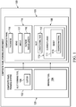
- composite panel forming environment 100 may be used to form composite panel 101 having bend 114.
- composite panel forming environment 100 has composite panel 101, and composite panel forming system 120.
- Composite panel 101 having bend 114 may be formed using composite panel forming system 120.
- composite panel forming system 120 includes slot forming tool 102 and bending tool 104.
- slot forming tool 102 may include cutter 106. Slot forming tool 102, with cutter 106, may be used to cut slot 108 with curved flange 110 in composite panel 101. Sheet 111 may be inserted into curved flange 110. Sheet 111 may be formed of desired material 113. In some illustrative examples, desired material 113 may be flexible enough to be bent into bend 114. Further, desired material 113 may be durable enough to withstand use on an aircraft without significant degradation. In some illustrative examples, sheet 111 may be a fiber reinforced material. In some illustrative examples, sheet 111 may be a composite sheet which is already cured. In one illustrative example, desired material 113 may be cured fiberglass.
- desired material 113 may comprise a polymeric material.
- Composite panel 101 with slot 108 and sheet 111 within curved flange 110 may then be bent about longitudinal axis 112 of slot 108 to form bend 114. Longitudinal axis 112 runs through the length of slot 108. Bend 114 has outside radius length 116 and angle 117. Sheet 111 may enable outside radius length 116 to be larger than an outside radius limited by thickness 118 of composite panel 101.
- Bending tool 104 may not be required, in these examples.
- Composite panel 101 may be bent into the desired shape by hand, without any other tools.
- bending tool 104 may be, for example, without limitation, a computer or human controlled machine that bends composite panel 101 into the desired shape for assembly with other components.
- bending tool 104 may be a mold on which composite panel 101 may be bent for further processing.
- slot forming tool 102 may take various forms.
- slot forming tool 102 may be a computer numerical control (CNC) router.
- CNC computer numerical control
- a non-limiting example of a computer numerical control that may be implemented as slot forming tool 102 may be a Cincinnati Milacron 1-Access Computer Numerical Control Router, which is available from MAG Cincinnati.
- CNC numerical control
- any numerical control (NC) or manual router capable of cutting slot 108 may be used.
- slot forming tool 102 may be implemented using a handheld or hand controlled router.
- slot 108 with curved flange 110 may be formed with cutter 106.
- Cutter 106 may have a shape for slot 108 with curved flange 110 such that movements of cutter 106 through composite panel 101 form slot 108 with curved flange 110.
- composite panel 101 may already be cured.
- composite panel forming environment 100 in Figure 1 is not meant to imply physical or architectural limitations to the manner in which an illustrative embodiment may be implemented. Other components in addition to or in place of the ones illustrated may be used. Some components may be unnecessary. Also, the blocks are presented to illustrate some functional components. One or more of these blocks may be combined, divided, or combined and divided into different blocks when implemented in an illustrative embodiment.
- composite panel forming environment 100 may further include a composite panel manufacturing system. This composite panel manufacturing system may be used to manufacture composite panel 101 prior to bending composite panel 101. Further, although not shown in Figure 1 , composite panel 101 may be formed of a first composite layer, a filler layer, and a second composite layer.
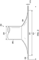
- Cutter 200 may be a physical embodiment of cutter 106 used by slot forming tool 102 in Figure 1 .
- cutter 200 has shaft 202 and flanged end 204.
- Cutter 200 may be used to create a slot, such as slot 108 in Figure 1 .
- Shaft 202 may have thickness 208.
- Flanged end 204 may have width 210. Width 210 of flanged end 204 may be used to form a slot having a desirable width.
- Edge 206 of flanged end 204 may have thickness 212 and width 214.
- the dimensions of cutter 200 may be used to process a composite panel to form a bend as desired.
- Cutter 200 may be made from different materials, such as, for example, without limitation, steel, aluminum composite, or any other suitable material. These and other dimensions provided in the various illustrative embodiments are merely examples of one implementation. Other illustrative embodiments may use other dimensions or parameters.
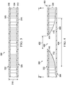
- composite panel 300 may be a physical implementation of composite panel 101 in Figure 1 .
- Composite panel 300 may include composite layer 302, also referred to as a first face sheet, filler layer 304, and composite layer 306 or second face sheet.
- Composite layer 302 may be formed from two composite plies, plies 308 and 310.
- composite layer 306 also may include two composite plies, ply 312 and ply 314.
- the number of plies or sub-layers that form composite layer 302 and composite layer 306 may vary, depending on the particular implementation. For example, without limitation, in some implementations, one ply may be used, while in other implementations three plies may be used. The exact number of plies may vary, depending on at least one of the particular uses or implementations.
- the phrase "at least one of,” when used with a list of items, means different combinations of one or more of the listed items may be used and only one of each item in the list may be needed.
- “at least one of item A, item B, or item C” may include, without limitation, item A, item A and item B, or item B. This example also may include item A, item B, and item C or item B and item C. Of course, any combinations of these items may be present.
- "at least one of” may be, for example, without limitation, two of item A, one of item B, and ten of item C; four of item B and seven of item C; and other suitable combinations.
- the item may be a particular object, thing, or a category. In other words, at least one of means any combination of items and number of items may be used from the list but not all of the items in the list are required.
- Composite layer 302 may be formed of plies having a number of orientations.
- orientations include, for example, without limitation, ply directions of 0 degrees, +/- 45 degrees, and 90 degrees; and ply directions of 0 degrees, +/- 30 degrees, +/- 60 degrees, and 90 degrees.
- the materials that may be used in composite layer 302 and composite layer 306 may take the form of a resin pre-impregnated fabric.
- This type of fabric also may be referred to as a pre-preg fabric.
- These types of reinforcements may take the form of woven fabrics, roving, and unidirectional tape.
- the resin and curing agent may be impregnated into a reinforcing fiber or material prior to layup.
- composite layer 302 and composite layer 306 may be, for example, without limitation, resin pre-impregnated fabrics with polyester and fiberglass, phenolic and fiberglass, epoxy and carbon fiber, epoxy, fiberglass, metallic, foil, screen, or any other suitable material.
- Filler layer 304 may be formed using a number of different materials. For example, without limitation, nomex® fibers, fiberglass, arimid, metallic, or other suitable materials may be used for filler layer 304. In these examples, filler layer 304 also may have a shape of a honeycomb matrix to form a honeycombed panel. Filler layer 304 may provide a structure to create the thickness desired for composite panel 300 without using heavy materials, such as those that may be found in composite layer 302 and composite layer 306. In some illustrative examples, filler layer 304 may also be called a core. In some illustrative examples in which filler layer 304 has a shape of a honeycomb matrix, filler layer 304 may be referred to as a honeycomb core.
- Filler layer 304 may provide composite panel 300 with a strength equivalent to or greater than a solid laminate. Filler layer 304 may provide composite panel 300 with a weight lower than a solid laminate. In some illustrative examples, separating composite layer 302 and composite layer 306 with filler layer 304 provides a desirable strength and a desirable weight. At least one of material of filler layer 304 and shape of filler layer 304 may affect the strength and weight of composite panel 300.
- composite panel 300 has thickness 316.
- Thickness 316 may be about one inch thick.
- Thickness 316 of composite panel 300 may vary, depending on the particular implementation. Examples of ranges include, for example, without limitation, between about 0.375 inches to about 1.5 inches, or any other suitable range.
- Composite panel 300 may be, in other examples, a range from about 0.25 inches to about 2.5 inches thick. In these examples, the radius bend may be up to about 3.4 times the thickness of composite panel 300. With these ranges, composite panel 300 may have a bend radius of up to about 1.7 inches when composite panel 300 is about 0.5 inches thick. When composite panel 300 is about 1 inch thick, this panel may have a bend radius of up to about 3.47 inches when composite panel 300 is about 0.5 inches thick. These examples are merely for purposes of illustration and the dimensions may vary as implementations vary.
- slot 400 may be formed after curing composite panel 300.
- a tool such as cutter 200 in Figure 2 , may be used to form a slot within composite panel 300 in Figure 3 .
- slot 400 may be formed within composite panel 300. Slot 400 may be formed in a single pass of a tool, such as cutter 200 in Figure 2 , through composite panel 300 in Figure 3 . Slot 400 may have bend slot width 402 along section 404. Thereafter, slot 400 widens in width to bend allowance width 406. The widening of the width of slot 400 increases to form curved flange 408. In this particular example, bend allowance width 406 may have a width corresponding to the width of flanged end 204 in cutter 200 in Figure 2 .
- the dimensions of cutter 200 may be selected to form slot 400 having desired dimensions.
- the dimensions of slot 400 may influence dimensions of a bend formed in composite panel 300. Accordingly, the dimensions of cutter 200 may be selected such that a bend in composite panel 300 having at least one of a desired angle and a desired outside radius length.
- Curve 410 of surface 412 may be selected to form a bend in composite panel 300 having at least one of a desired angle and a desired outside radius length in conjunction with bend slot width 402.
- Curve 414 of surface 416 may be selected to form a bend in composite panel 300 having at least one of a desired angle and a desired outside radius length in conjunction with bend slot width 402.
- FIG. 5 an illustration of a top view of a composite panel is depicted in accordance with an illustrative embodiment.
- a top view of composite panel 300 is shown in the direction of line 5-5 in Figure 4 .
- slot 400 may extend from side 500 to side 502 of composite panel 300.
- a cutter tool such as cutter 200 in Figure 2
- Dotted line 504 and dotted line 506 may illustrate the locations of edges of bend allowance width 406, which is not visible in this view.
- Slot 400 has longitudinal axis 508. As depicted, longitudinal axis 508 may run the length of slot 400 from side 500 to side 502.
- composite panel 300 may be bent about the longitudinal axis 508.
- FIG. 6 an illustration of a slot with a sheet is depicted in accordance with an illustrative embodiment. Specifically, a view of composite panel 300 with a sheet within curved flange 408 of slot 400. Sheet 602 may be a physical embodiment of sheet 111 of Figure 1 .
- Figure 6 is a view in the direction of line 6-6, in Figure 5 , which is also the view from Figure 3 and Figure 4 .
- Sheet 602 has thickness 604. As depicted, thickness 604 is less than thickness 606 of slot 400 at the edge of bend allowance width 406. Thickness 606 of slot 400 at the edge of bend allowance width 406 may be formed by thickness of edge 206 of flanged end 204 of Figure 2 .
- Figure 7 is an illustration of a composite panel in a bent configuration in accordance with an illustrative embodiment.
- composite panel 300 and sheet 602 may be bent around longitudinal axis 508 of slot 400.
- a tool such as bending tool 104 in Figure 1 , may be used to bend composite panel 300 and sheet 602.
- composite panel 300 has bend 700.
- Composite panel 300 may have angle 702. This angle may be about ninety degrees, in this example.
- Angle 702 may vary, depending of the particular embodiment. For example, angle 702 may be seventy-five degrees, eighty degrees, one-hundred twenty degrees, or any other suitable angle.
- bend 700 extends from point 704 to point 706. Outside radius length 708 of bend 700 is the distance from point 704 to point 706.
- the dimensions of slot 400 affect at least one of angle 702 and outside radius length 708.
- the dimensions of cutter 200 in Figure 2 affect the dimensions of slot 400. Accordingly, the dimensions of cutter 200 may be selected to form bend 700 having outside radius length 708. The dimensions of cutter 200 may be selected to form angle 702. By changing dimensions of cutter 200, at least one of outside radius length 708 and angle 702 of bend 700 may be changed. As depicted, sheet 602 and composite layer 302 form inner surface 710 of bend 700.
- Bend slot width 402 of slot 400 from Figures 4-6 may be selected to form bend 700.
- Bend slot width 402 may be configured such that edges of composite layer 302 contact sheet 602 after bending composite panel 300 to form bend 700.
- Bend slot width 402 may be configured such that edges of composite layer 302 are prevented from contacting each other after bending composite panel 300 to form bend 700.
- bend slot width 402 may be characterized as follows: BA > 2 ⁇ ⁇ R * _A_ 360
- BA may be bend allowance width 406 and R may be the corner radius.
- A may be a bend angle, such as angle 702.
- bend slot width 402 may be characterized as follows: BS > BA ⁇ 2K R ⁇ T BS may be bend slot width 402, BA may be bend allowance width 406, K may be TAN(A/2), and T may be the thickness of composite panel 300.
- thickness 316 of composite panel 300 may not limit outside radius length 708.
- sheet 602 may be contained within slot 400 without adhesives or fasteners.
- Sheet 602 may cover exposed filler layer 304.
- Sheet 602 may comprise a desired material and a decorative layer.
- the desired material comprises cured fiberglass.
- a decorative layer may be adhered to the cured fiberglass.
- the decorative layer may provide at least one of a desired color or desired texture.
- sheet 602 may include information such as text, a sign, or other graphical indicators.
- the decorative layer may include information such as text, a sign, or other graphical indicators.
- Sheet 602 may contain or form a portion of a flexible organic light emitting diode (OLED) display. In this manner, sheet 602 also may provide light, information, or perform other suitable functions.
- the decorative layer may form inner surface 710 of bend 700.
- FIG. 2-7 The different components shown in Figures 2-7 may be combined with components in Figure 1 , used with components in Figure 1 , or a combination of the two. Additionally, some of the components in Figures 2-7 may be illustrative examples of how components shown in block form in Figure 1 can be implemented as physical structures.
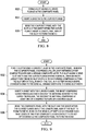
- FIG 8 an illustration of a flowchart of a process for forming a bend in a composite panel is depicted in accordance with an illustrative embodiment.
- the process illustrated in Figure 8 may be implemented in composite panel forming environment 100.
- the process may be implemented using composite panel forming system 120 in composite panel forming environment 100 to form composite panel 101.
- this process may form bend 114 in composite panel 101 in Figure 1 .
- the process may begin by forming a slot having a curved flange in the composite panel (operation 802 ).
- the slot may be slot 108 of Figure 1 .
- the slot may be slot 400 in Figure 4 .
- the forming step comprises cutting slot 400 with a tool, wherein the tool is cutter 200 having a shape corresponding to bend allowance width 406 and bend slot width 402.
- Slot 400 may be formed in composite layer 302 and filler layer 304. Slot 400 may be formed by cutting away a portion of composite layer 302, and portions of filler layer 304 of composite panel 300.
- slot 400 with curved flange 408 may be cut into composite panel 300.
- the process may then insert a sheet into the curved flange (operation 804 ).
- the sheet may be sheet 111 of Figure 1 .
- the sheet may be formed of cured fiberglass.
- the process may bend composite panel 300 with slot 400 and sheet 111 within curved flange 408 about longitudinal axis 508 of slot 400 to form the bend (operation 806 ).
- sheet 111 may be contained within slot 108 without adhesives or fasteners.
- FIG. 9 an illustration of a flowchart of a process for forming a bend in a composite panel is depicted in accordance with an illustrative embodiment.
- the process illustrated in Figure 9 may be implemented to form bend 114 in composite panel 101 in Figure 1 .
- the process may begin by forming a slot 400 having a curved flange 408 in the composite panel 300, in which the composite panel 300 comprises a filler layer 304 between a first composite layer and a second composite layer, the slot 400 having a bend slot width 402 and the curved flange 408 having a bend allowance width 406 larger than the bend slot width 402, in which forming comprises cutting the slot 400 with a tool , in which the tool is a cutter 200 having a shape corresponding to the bend allowance width 406 and the bend slot width 402 (operation 902 ).
- Tool may be slot forming tool 102.
- First composite layer may be composite layer 302.
- Second composite layer may be composite layer 306.
- the slot may be slot 108 in Figure 1 .
- the slot may be formed by removing a portion of the first composite layer and a portion of the filler layer.
- the composite panel may be composite panel 300 having composite layer 302, filler layer 304, and composite layer 306.
- the process may then insert a sheet into the curved flange, the sheet comprising cured fiberglass and a decorative material adhered to the cured fiberglass, the decorative material comprising at least one of a desired texture or a desired color (operation 904 ).
- the sheet may be sheet 602 of Figure 6 .
- the process may then bend the composite panel with the slot and the sheet within the curved flange about the longitudinal axis of the slot to form the bend 700, in which the bend slot width is configured such that edges of the first composite layer contact the sheet after bending the composite panel to form the bend (operation 906 ).
- the sheet may be contained within the slot without adhesives or fasteners. Specifically, contact between the sheet and at least one of the filler layer, the first composite layer, and the second composite layer holds the sheet within the slot. The process terminates thereafter.
- each block in the flowcharts or block diagrams may represent a module, a segment, a function, and/or a portion of an operation or step.
- the function or functions noted in the blocks may occur out of the order noted in the figures.
- two blocks shown in succession may be executed substantially concurrently, or the blocks may sometimes be performed in the reverse order, depending upon the functionality involved.
- other blocks may be added in addition to the illustrated blocks in a flowchart or block diagram.
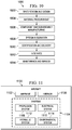
- aircraft manufacturing and service method 1000 may be described in the context of aircraft manufacturing and service method 1000 as shown in Figure 10 and aircraft 1100 as shown in Figure 11 .
- Figure 10 an illustration of a block diagram of an aircraft manufacturing and service method is depicted in accordance with an illustrative embodiment.
- aircraft manufacturing and service method 1000 may include specification and design 1002 of aircraft 1100 in Figure 11 and material procurement 1004.
- aircraft 1100 in Figure 11 During production, component and subassembly manufacturing 1006 and system integration 1008 of aircraft 1100 in Figure 11 takes place. Thereafter, aircraft 1100 in Figure 11 may go through certification and delivery 1010 in order to be placed in service 1012. While in service 1012 by a customer, aircraft 1100 in Figure 11 is scheduled for routine maintenance and service 1014, which may include modification, reconfiguration, refurbishment, and other maintenance or service.
- Each of the processes of aircraft manufacturing and service method 1000 may be performed or carried out by a system integrator, a third party, and/or an operator.
- the operator may be a customer.
- a system integrator may include, without limitation, any number of aircraft manufacturers and major-system subcontractors
- a third party may include, without limitation, any number of vendors, subcontractors, and suppliers
- an operator may be an airline, a leasing company, a military entity, a service organization, and so on.
- aircraft 1100 is produced by aircraft manufacturing and service method 1000 in Figure 10 and may include airframe 1102 with plurality of systems 1104 and interior 1106.
- systems 1104 include one or more of propulsion system 1108, electrical system 1110, hydraulic system 1112, and environmental system 1114. Any number of other systems may be included.
- propulsion system 1108, electrical system 1110, hydraulic system 1112, and environmental system 1114 Any number of other systems may be included.
- an aerospace example is shown, different illustrative embodiments may be applied to other industries, such as the automotive industry.
- Apparatuses and methods embodied herein may be employed during at least one of the stages of aircraft manufacturing and service method 1000 in Figure 10 .
- One or more illustrative embodiments may be used during component and subassembly manufacturing 1006.
- composite panel 101 with bend 114 in Figure 1 may be used during at least one of component and subassembly manufacturing 1006 or system integration 1008.
- composite panel 101 with bend 114 in Figure 1 may be formed during at least one of component and subassembly manufacturing 1006 or system integration 1008.
- Composite panel 101 with bend 114 may be a part for aircraft 1100.
- composite panel 101 with bend 114 in Figure 1 may be a part of interior 1106 of aircraft 1100.
- composite panel 101 with bend 114 in Figure 1 may be joined with other parts during component and subassembly manufacturing 1006. Yet further, composite panel 101 with bend 114 in Figure 1 may also be used to perform replacements and upgrades during maintenance and service 1014. In particular during maintenance and service 1014, bends may be formed in composite panels used during routine maintenance, upgrades, refurbishment, and other operations that may be performed during maintenance and service 1014. For example, aircraft 1100 may be inspected during scheduled maintenance for aircraft 1100.
- one or more apparatus embodiments, method embodiments, or a combination thereof may be utilized during system integration 1008 and certification and delivery 1010, for example, by substantially expediting assembly of or reducing the cost of aircraft 1100.
- one or more of apparatus embodiments, method embodiments, or a combination thereof may be utilized while aircraft 1100 is in service, for example and without limitation, to maintenance and service 1016.
- the illustrative embodiments provide a method and apparatus for forming a bend in a composite panel. Specifically, the illustrative embodiments provide a method and apparatus for forming a bend in a composite panel in which an outside radius length of the bend is not limited by a thickness of the composite panel.
- sheet 602 By inserting sheet 602 into curved flange 408 of slot 400, sheet 602 may form part of inner surface 710 of bend 700. Sheet 602 may cover exposed portions of filler layer 304. Further, sheet 602 may provide at least one of a desired color and a desired texture.
- Bend slot width 402 may be configured such that edges of composite layer 302 contact sheet 602 after bending composite panel 300 to form bend 700. Accordingly, sheet 602 may be held within slot 400 without adhesive or fasteners. Use of sheet 602 may allow for composite panel 300 to have a lower weight than the thickness of composite panel 300 was increased so that edges of composite layer 302 touch each other. Use of sheet 602 may allow for composite panel 300 to have a lower weight than if a cover were fastened or adhered over an exposed filler layer.
Landscapes
- Engineering & Computer Science (AREA)
- Mechanical Engineering (AREA)
- Architecture (AREA)
- Life Sciences & Earth Sciences (AREA)
- Structural Engineering (AREA)
- Civil Engineering (AREA)
- Forests & Forestry (AREA)
- Chemical & Material Sciences (AREA)
- Composite Materials (AREA)
- Wood Science & Technology (AREA)
- Moulding By Coating Moulds (AREA)
- Shaping Of Tube Ends By Bending Or Straightening (AREA)
- Bending Of Plates, Rods, And Pipes (AREA)
- Laminated Bodies (AREA)
Applications Claiming Priority (1)
| Application Number | Priority Date | Filing Date | Title |
|---|---|---|---|
| US14/052,256 US9205616B2 (en) | 2013-10-11 | 2013-10-11 | Bends in composite panels |
Publications (2)
| Publication Number | Publication Date |
|---|---|
| EP2860018A1 EP2860018A1 (en) | 2015-04-15 |
| EP2860018B1 true EP2860018B1 (en) | 2019-03-27 |
Family
ID=51751898
Family Applications (1)
| Application Number | Title | Priority Date | Filing Date |
|---|---|---|---|
| EP14187328.1A Active EP2860018B1 (en) | 2013-10-11 | 2014-10-01 | Bends in composite panels |
Country Status (10)
| Country | Link |
|---|---|
| US (2) | US9205616B2 (zh) |
| EP (1) | EP2860018B1 (zh) |
| JP (2) | JP6272202B2 (zh) |
| KR (1) | KR102211579B1 (zh) |
| CN (1) | CN104552904B (zh) |
| BR (1) | BR102014020632B1 (zh) |
| CA (1) | CA2859486C (zh) |
| ES (1) | ES2732364T3 (zh) |
| PT (1) | PT2860018T (zh) |
| TR (1) | TR201908244T4 (zh) |
Families Citing this family (9)
| Publication number | Priority date | Publication date | Assignee | Title |
|---|---|---|---|---|
| US9205616B2 (en) | 2013-10-11 | 2015-12-08 | The Boeing Company | Bends in composite panels |
| US20170284623A1 (en) * | 2016-03-31 | 2017-10-05 | GM Global Technology Operations LLC | Methods and apparatus for free-form illumination assemblies |
| US11426966B2 (en) | 2018-03-16 | 2022-08-30 | Jetcoat (Shanghai) Co Ltd, China | Bendable panel |
| CN109291471B (zh) * | 2018-09-18 | 2021-05-07 | 株洲时代新材料科技股份有限公司 | 一种厚制件玻璃钢层合板切割打磨加工方法 |
| US11077630B1 (en) | 2020-02-04 | 2021-08-03 | The Boeing Company | Molded laminated structure with negative draft angles and associated methods of manufacturing |
| CN113145908B (zh) * | 2021-05-27 | 2021-09-14 | 中国电子科技集团公司第二十九研究所 | 高温宽带电磁吸收复合材料的曲面薄壳结构的加工方法 |
| US11780021B2 (en) * | 2021-09-10 | 2023-10-10 | Rohr, Inc. | Component with structured panel(s) and methods for forming the component |
| US11925971B2 (en) | 2021-09-10 | 2024-03-12 | Rohr, Inc. | Component with structured panel(s) and methods for forming the component |
| CN114951735B (zh) * | 2022-06-14 | 2023-06-16 | 湖北三江航天红阳机电有限公司 | 一种复合舱段的加工方法 |
Family Cites Families (53)
| Publication number | Priority date | Publication date | Assignee | Title |
|---|---|---|---|---|
| US1602164A (en) | 1921-12-22 | 1926-10-05 | Flintkote Co | Roof |
| US1671084A (en) * | 1927-06-06 | 1928-05-22 | Haskelite Mfg Corp | Joint filler in angle of plymetl wall |
| BE398364A (zh) | 1932-09-13 | |||
| US2026650A (en) * | 1935-01-05 | 1936-01-07 | Rudolph F Onsrud | Wood joint and corner construction |
| US2155969A (en) | 1936-04-13 | 1939-04-25 | Mengel Body Company | Round corner joint |
| US2135000A (en) | 1936-10-13 | 1938-11-01 | Automatic Machinery Corp | Round corner |
| US2505789A (en) | 1945-12-12 | 1950-05-02 | Glenn H Norquist | Grooving laminated plywood |
| US2922561A (en) | 1956-11-01 | 1960-01-26 | Carton Associates Inc | Cartons |
| US3122302A (en) | 1963-01-07 | 1964-02-25 | Mead Corp | Article carrier |
| US3456380A (en) | 1966-08-08 | 1969-07-22 | Margaret M Cameron | Illustrative object forming bookcover |
| US3341908A (en) | 1966-10-21 | 1967-09-19 | Mead Corp | Panel interlocking means |
| US3969868A (en) | 1970-03-02 | 1976-07-20 | Winnebago Industries, Inc. | Insulation structure |
| US4024684A (en) | 1971-06-02 | 1977-05-24 | H. H. Robertson Company | Pre-notched building panel with splice plate and method of preparing the same |
| US3890108A (en) | 1973-02-09 | 1975-06-17 | Hughes Aircraft Co | Structural panel bent from laminated honeycomb |
| US4160052A (en) * | 1977-08-15 | 1979-07-03 | Lof Plastics Inc. | Corner for decorative and protective molding strip |
| FR2409855A1 (fr) | 1977-11-24 | 1979-06-22 | Chollet Jacques | Element prefabrique destine notamment a la construction de gaines |
| US4387128A (en) | 1979-07-12 | 1983-06-07 | Brymitre Limited | Foldable structure |
| US4671470A (en) | 1985-07-15 | 1987-06-09 | Beech Aircraft Corporation | Method for fastening aircraft frame elements to sandwich skin panels covering same using woven fiber connectors |
| US4715592A (en) | 1985-12-06 | 1987-12-29 | Lewis Julie M | Accouchement apparatus |
| AT388704B (de) * | 1986-06-12 | 1989-08-25 | Isovolta | Laminatplatte sowie daraus hergestellter bauteil mit zumindest einem gerundeten oberflaechenbereich |
| DE3738881A1 (de) | 1987-11-16 | 1989-05-24 | Ice Pack Service Ag | Verschluss zum verschliessen von kunststoffbeuteln und dergleichen |
| US4917747A (en) | 1989-02-24 | 1990-04-17 | The Boeing Company | Method of making crushed core molded panels |
| NZ233510A (en) | 1989-05-03 | 1993-09-27 | Robert John Duncanson | Panels joined by tongue and recess formation |
| US5331758A (en) | 1991-07-10 | 1994-07-26 | Romick Jerome M | Single piece transparent label holder |
| US5125133A (en) | 1991-11-25 | 1992-06-30 | Hollister Incorporated | Ostomy pouch clamp with hinge-supplementing guide blade |
| AU5331894A (en) | 1992-10-23 | 1994-05-24 | Dicab Barracuda Pty Ltd | A sandwich panel for angular forming |
| CA2102004C (en) | 1992-10-30 | 2001-05-01 | Donald E. Dahowski | Thermoformable plastic framing/connecting strip |
| US5589016A (en) | 1994-04-29 | 1996-12-31 | The Boeing Company | Prescored foam for panel fabrication |
| US5509212A (en) | 1994-09-12 | 1996-04-23 | Henricksen; Douglas A. | Folding and locking drafting aid apparatus and method |
| GB2306556A (en) | 1995-11-02 | 1997-05-07 | Luke Lo | Air bag clip |
| JPH09131788A (ja) * | 1995-11-13 | 1997-05-20 | Jamco Corp | ハニカムパネルの加工方法 |
| US5755068A (en) | 1995-11-17 | 1998-05-26 | Ormiston; Fred I. | Veneer panels and method of making |
| US5653003A (en) | 1996-04-04 | 1997-08-05 | Freeman; William David | Shoulder harness recoil restraint clip |
| DE59611262D1 (de) | 1996-07-18 | 2005-09-29 | Alcan Tech & Man Ag | Verbundplatte |
| AUPO851497A0 (en) | 1997-08-11 | 1997-09-04 | Lee, John Bartholemew | A building panel and method of forming same |
| US6164477A (en) | 1997-11-20 | 2000-12-26 | The Boeing Company | Combined mortise and tenon joint feature |
| US5940935A (en) | 1998-04-23 | 1999-08-24 | Nice-Pak Products | Hinge connection |
| US6453973B1 (en) | 1998-08-28 | 2002-09-24 | Ralph Russo | Modular panel structure |
| JP3597441B2 (ja) | 2000-03-16 | 2004-12-08 | 株式会社日立製作所 | 積層材の曲げ加工方法 |
| JP2003034354A (ja) | 2001-07-02 | 2003-02-04 | Mead Corp:The | カートンブランク |
| US6685085B2 (en) | 2002-02-08 | 2004-02-03 | Arvco Container Corporation | Tamper-resistant food container |
| US6968971B2 (en) | 2002-08-07 | 2005-11-29 | The Boeing Company | Endcap assembly for a stowage bin |
| AT413228B (de) | 2002-08-19 | 2005-12-15 | Kaindl M | Verkleidungsplatte |
| US7013535B2 (en) | 2003-01-15 | 2006-03-21 | Illinois Tool Works Inc. | Web end |
| US20070144100A1 (en) | 2003-05-14 | 2007-06-28 | Andrade Daniel J | Synthetic resin structures and mountings for such structures |
| RU2263829C2 (ru) | 2004-01-13 | 2005-11-10 | Кузнецова Елна Юрьевна | Узел соединения плоских деталей |
| BRPI0609143A2 (pt) | 2005-03-17 | 2011-09-13 | Ind Origami Llc | folha de material para a formação de uma estrutura estrutural tridimensional, viga oca e armação de exoesqueleto |
| US7302150B2 (en) | 2006-04-27 | 2007-11-27 | The Boeing Company | Illuminated latch indicator assembly |
| US7887249B2 (en) | 2006-06-15 | 2011-02-15 | The Boeing Company | Internal finger joint |
| NL1033895C2 (nl) * | 2007-05-25 | 2008-11-28 | Fits Holding B V | Werkwijze voor het vervaardigen van een voorwerp uit een sandwichstructuur met een verstevigde hoek en een dergelijk voorwerp. |
| US8312754B2 (en) | 2007-10-25 | 2012-11-20 | The Boeing Company | Method for forming bends in composite panels and composite panels made thereby |
| US8234901B2 (en) | 2007-10-25 | 2012-08-07 | The Boeing Company | Method to create bends in composite panels |
| US9205616B2 (en) | 2013-10-11 | 2015-12-08 | The Boeing Company | Bends in composite panels |
-
2013
- 2013-10-11 US US14/052,256 patent/US9205616B2/en active Active
-
2014
- 2014-08-07 KR KR1020140101451A patent/KR102211579B1/ko active IP Right Grant
- 2014-08-15 CA CA2859486A patent/CA2859486C/en active Active
- 2014-08-21 BR BR102014020632-9A patent/BR102014020632B1/pt active IP Right Grant
- 2014-09-30 JP JP2014200909A patent/JP6272202B2/ja active Active
- 2014-09-30 CN CN201410521809.9A patent/CN104552904B/zh active Active
- 2014-10-01 EP EP14187328.1A patent/EP2860018B1/en active Active
- 2014-10-01 PT PT14187328T patent/PT2860018T/pt unknown
- 2014-10-01 TR TR2019/08244T patent/TR201908244T4/tr unknown
- 2014-10-01 ES ES14187328T patent/ES2732364T3/es active Active
-
2015
- 2015-12-07 US US14/961,718 patent/US9908283B2/en active Active
-
2017
- 2017-12-28 JP JP2017253276A patent/JP6466559B2/ja active Active
Non-Patent Citations (1)
| Title |
|---|
| None * |
Also Published As
| Publication number | Publication date |
|---|---|
| PT2860018T (pt) | 2019-05-28 |
| EP2860018A1 (en) | 2015-04-15 |
| BR102014020632A2 (pt) | 2016-08-16 |
| US9205616B2 (en) | 2015-12-08 |
| JP2018094926A (ja) | 2018-06-21 |
| JP2015074229A (ja) | 2015-04-20 |
| ES2732364T3 (es) | 2019-11-22 |
| CA2859486C (en) | 2016-09-20 |
| JP6272202B2 (ja) | 2018-01-31 |
| US9908283B2 (en) | 2018-03-06 |
| US20160158995A1 (en) | 2016-06-09 |
| CA2859486A1 (en) | 2015-04-11 |
| US20150101738A1 (en) | 2015-04-16 |
| KR102211579B1 (ko) | 2021-02-03 |
| CN104552904B (zh) | 2018-05-01 |
| TR201908244T4 (tr) | 2019-06-21 |
| CN104552904A (zh) | 2015-04-29 |
| KR20150042695A (ko) | 2015-04-21 |
| BR102014020632B1 (pt) | 2020-11-24 |
| JP6466559B2 (ja) | 2019-02-06 |
Similar Documents
| Publication | Publication Date | Title |
|---|---|---|
| EP2860018B1 (en) | Bends in composite panels | |
| EP2671707B1 (en) | Optimized cross-ply orientation in aircraft wing skin | |
| US8234901B2 (en) | Method to create bends in composite panels | |
| US8312754B2 (en) | Method for forming bends in composite panels and composite panels made thereby | |
| EP2666622B1 (en) | Skin-stiffener transition assembly, method of manufacture and application of said skin-stiffener transition assembly | |
| EP2406071B1 (en) | Composite structures employing quasi-isotropic laminates | |
| US6676785B2 (en) | Method of clinching the top and bottom ends of Z-axis fibers into the respective top and bottom surfaces of a composite laminate | |
| AU2019202566B2 (en) | Folded composite filler | |
| EP3293104B1 (en) | Open-channel stiffener | |
| EP2502734A1 (en) | Method of fabricating a compound contoured composite beam | |
| EP3144125B1 (en) | Panel and associated closeout method |
Legal Events
| Date | Code | Title | Description |
|---|---|---|---|
| PUAI | Public reference made under article 153(3) epc to a published international application that has entered the european phase |
Free format text: ORIGINAL CODE: 0009012 |
|
| 17P | Request for examination filed |
Effective date: 20141001 |
|
| AK | Designated contracting states |
Kind code of ref document: A1 Designated state(s): AL AT BE BG CH CY CZ DE DK EE ES FI FR GB GR HR HU IE IS IT LI LT LU LV MC MK MT NL NO PL PT RO RS SE SI SK SM TR |
|
| AX | Request for extension of the european patent |
Extension state: BA ME |
|
| RIC1 | Information provided on ipc code assigned before grant |
Ipc: B29C 70/02 20060101ALN20180222BHEP Ipc: B29C 53/06 20060101AFI20180222BHEP Ipc: B32B 3/12 20060101ALN20180222BHEP Ipc: B26D 3/06 20060101ALN20180222BHEP |
|
| GRAP | Despatch of communication of intention to grant a patent |
Free format text: ORIGINAL CODE: EPIDOSNIGR1 |
|
| STAA | Information on the status of an ep patent application or granted ep patent |
Free format text: STATUS: GRANT OF PATENT IS INTENDED |
|
| INTG | Intention to grant announced |
Effective date: 20180418 |
|
| GRAJ | Information related to disapproval of communication of intention to grant by the applicant or resumption of examination proceedings by the epo deleted |
Free format text: ORIGINAL CODE: EPIDOSDIGR1 |
|
| STAA | Information on the status of an ep patent application or granted ep patent |
Free format text: STATUS: REQUEST FOR EXAMINATION WAS MADE |
|
| GRAP | Despatch of communication of intention to grant a patent |
Free format text: ORIGINAL CODE: EPIDOSNIGR1 |
|
| STAA | Information on the status of an ep patent application or granted ep patent |
Free format text: STATUS: GRANT OF PATENT IS INTENDED |
|
| INTC | Intention to grant announced (deleted) | ||
| RIC1 | Information provided on ipc code assigned before grant |
Ipc: B32B 3/12 20060101ALN20180913BHEP Ipc: B26D 3/06 20060101ALN20180913BHEP Ipc: B29C 53/06 20060101AFI20180913BHEP Ipc: B29C 70/02 20060101ALN20180913BHEP |
|
| INTG | Intention to grant announced |
Effective date: 20181005 |
|
| GRAS | Grant fee paid |
Free format text: ORIGINAL CODE: EPIDOSNIGR3 |
|
| GRAA | (expected) grant |
Free format text: ORIGINAL CODE: 0009210 |
|
| STAA | Information on the status of an ep patent application or granted ep patent |
Free format text: STATUS: THE PATENT HAS BEEN GRANTED |
|
| AK | Designated contracting states |
Kind code of ref document: B1 Designated state(s): AL AT BE BG CH CY CZ DE DK EE ES FI FR GB GR HR HU IE IS IT LI LT LU LV MC MK MT NL NO PL PT RO RS SE SI SK SM TR |
|
| REG | Reference to a national code |
Ref country code: GB Ref legal event code: FG4D |
|
| REG | Reference to a national code |
Ref country code: CH Ref legal event code: EP |
|
| REG | Reference to a national code |
Ref country code: AT Ref legal event code: REF Ref document number: 1112546 Country of ref document: AT Kind code of ref document: T Effective date: 20190415 |
|
| REG | Reference to a national code |
Ref country code: IE Ref legal event code: FG4D |
|
| REG | Reference to a national code |
Ref country code: DE Ref legal event code: R096 Ref document number: 602014043535 Country of ref document: DE |
|
| REG | Reference to a national code |
Ref country code: PT Ref legal event code: SC4A Ref document number: 2860018 Country of ref document: PT Date of ref document: 20190528 Kind code of ref document: T Free format text: AVAILABILITY OF NATIONAL TRANSLATION Effective date: 20190502 |
|
| REG | Reference to a national code |
Ref country code: SE Ref legal event code: TRGR |
|
| PG25 | Lapsed in a contracting state [announced via postgrant information from national office to epo] |
Ref country code: NO Free format text: LAPSE BECAUSE OF FAILURE TO SUBMIT A TRANSLATION OF THE DESCRIPTION OR TO PAY THE FEE WITHIN THE PRESCRIBED TIME-LIMIT Effective date: 20190627 Ref country code: FI Free format text: LAPSE BECAUSE OF FAILURE TO SUBMIT A TRANSLATION OF THE DESCRIPTION OR TO PAY THE FEE WITHIN THE PRESCRIBED TIME-LIMIT Effective date: 20190327 Ref country code: LT Free format text: LAPSE BECAUSE OF FAILURE TO SUBMIT A TRANSLATION OF THE DESCRIPTION OR TO PAY THE FEE WITHIN THE PRESCRIBED TIME-LIMIT Effective date: 20190327 |
|
| REG | Reference to a national code |
Ref country code: NL Ref legal event code: MP Effective date: 20190327 |
|
| PG25 | Lapsed in a contracting state [announced via postgrant information from national office to epo] |
Ref country code: GR Free format text: LAPSE BECAUSE OF FAILURE TO SUBMIT A TRANSLATION OF THE DESCRIPTION OR TO PAY THE FEE WITHIN THE PRESCRIBED TIME-LIMIT Effective date: 20190628 Ref country code: HR Free format text: LAPSE BECAUSE OF FAILURE TO SUBMIT A TRANSLATION OF THE DESCRIPTION OR TO PAY THE FEE WITHIN THE PRESCRIBED TIME-LIMIT Effective date: 20190327 Ref country code: NL Free format text: LAPSE BECAUSE OF FAILURE TO SUBMIT A TRANSLATION OF THE DESCRIPTION OR TO PAY THE FEE WITHIN THE PRESCRIBED TIME-LIMIT Effective date: 20190327 Ref country code: LV Free format text: LAPSE BECAUSE OF FAILURE TO SUBMIT A TRANSLATION OF THE DESCRIPTION OR TO PAY THE FEE WITHIN THE PRESCRIBED TIME-LIMIT Effective date: 20190327 Ref country code: BG Free format text: LAPSE BECAUSE OF FAILURE TO SUBMIT A TRANSLATION OF THE DESCRIPTION OR TO PAY THE FEE WITHIN THE PRESCRIBED TIME-LIMIT Effective date: 20190627 Ref country code: RS Free format text: LAPSE BECAUSE OF FAILURE TO SUBMIT A TRANSLATION OF THE DESCRIPTION OR TO PAY THE FEE WITHIN THE PRESCRIBED TIME-LIMIT Effective date: 20190327 |
|
| REG | Reference to a national code |
Ref country code: AT Ref legal event code: MK05 Ref document number: 1112546 Country of ref document: AT Kind code of ref document: T Effective date: 20190327 |
|
| PG25 | Lapsed in a contracting state [announced via postgrant information from national office to epo] |
Ref country code: AL Free format text: LAPSE BECAUSE OF FAILURE TO SUBMIT A TRANSLATION OF THE DESCRIPTION OR TO PAY THE FEE WITHIN THE PRESCRIBED TIME-LIMIT Effective date: 20190327 Ref country code: CZ Free format text: LAPSE BECAUSE OF FAILURE TO SUBMIT A TRANSLATION OF THE DESCRIPTION OR TO PAY THE FEE WITHIN THE PRESCRIBED TIME-LIMIT Effective date: 20190327 Ref country code: RO Free format text: LAPSE BECAUSE OF FAILURE TO SUBMIT A TRANSLATION OF THE DESCRIPTION OR TO PAY THE FEE WITHIN THE PRESCRIBED TIME-LIMIT Effective date: 20190327 Ref country code: EE Free format text: LAPSE BECAUSE OF FAILURE TO SUBMIT A TRANSLATION OF THE DESCRIPTION OR TO PAY THE FEE WITHIN THE PRESCRIBED TIME-LIMIT Effective date: 20190327 Ref country code: SK Free format text: LAPSE BECAUSE OF FAILURE TO SUBMIT A TRANSLATION OF THE DESCRIPTION OR TO PAY THE FEE WITHIN THE PRESCRIBED TIME-LIMIT Effective date: 20190327 |
|
| REG | Reference to a national code |
Ref country code: ES Ref legal event code: FG2A Ref document number: 2732364 Country of ref document: ES Kind code of ref document: T3 Effective date: 20191122 |
|
| PG25 | Lapsed in a contracting state [announced via postgrant information from national office to epo] |
Ref country code: PL Free format text: LAPSE BECAUSE OF FAILURE TO SUBMIT A TRANSLATION OF THE DESCRIPTION OR TO PAY THE FEE WITHIN THE PRESCRIBED TIME-LIMIT Effective date: 20190327 Ref country code: SM Free format text: LAPSE BECAUSE OF FAILURE TO SUBMIT A TRANSLATION OF THE DESCRIPTION OR TO PAY THE FEE WITHIN THE PRESCRIBED TIME-LIMIT Effective date: 20190327 |
|
| PG25 | Lapsed in a contracting state [announced via postgrant information from national office to epo] |
Ref country code: IS Free format text: LAPSE BECAUSE OF FAILURE TO SUBMIT A TRANSLATION OF THE DESCRIPTION OR TO PAY THE FEE WITHIN THE PRESCRIBED TIME-LIMIT Effective date: 20190727 Ref country code: AT Free format text: LAPSE BECAUSE OF FAILURE TO SUBMIT A TRANSLATION OF THE DESCRIPTION OR TO PAY THE FEE WITHIN THE PRESCRIBED TIME-LIMIT Effective date: 20190327 |
|
| REG | Reference to a national code |
Ref country code: DE Ref legal event code: R097 Ref document number: 602014043535 Country of ref document: DE |
|
| REG | Reference to a national code |
Ref country code: DE Ref legal event code: R082 Ref document number: 602014043535 Country of ref document: DE Representative=s name: MAIER, LL.M., MICHAEL C., DE Ref country code: DE Ref legal event code: R082 Ref document number: 602014043535 Country of ref document: DE Representative=s name: BOULT WADE TENNANT LLP, DE |
|
| PG25 | Lapsed in a contracting state [announced via postgrant information from national office to epo] |
Ref country code: DK Free format text: LAPSE BECAUSE OF FAILURE TO SUBMIT A TRANSLATION OF THE DESCRIPTION OR TO PAY THE FEE WITHIN THE PRESCRIBED TIME-LIMIT Effective date: 20190327 |
|
| PLBE | No opposition filed within time limit |
Free format text: ORIGINAL CODE: 0009261 |
|
| STAA | Information on the status of an ep patent application or granted ep patent |
Free format text: STATUS: NO OPPOSITION FILED WITHIN TIME LIMIT |
|
| REG | Reference to a national code |
Ref country code: DE Ref legal event code: R082 Ref document number: 602014043535 Country of ref document: DE Representative=s name: BOULT WADE TENNANT LLP, DE |
|
| PG25 | Lapsed in a contracting state [announced via postgrant information from national office to epo] |
Ref country code: SI Free format text: LAPSE BECAUSE OF FAILURE TO SUBMIT A TRANSLATION OF THE DESCRIPTION OR TO PAY THE FEE WITHIN THE PRESCRIBED TIME-LIMIT Effective date: 20190327 |
|
| 26N | No opposition filed |
Effective date: 20200103 |
|
| PG25 | Lapsed in a contracting state [announced via postgrant information from national office to epo] |
Ref country code: MC Free format text: LAPSE BECAUSE OF FAILURE TO SUBMIT A TRANSLATION OF THE DESCRIPTION OR TO PAY THE FEE WITHIN THE PRESCRIBED TIME-LIMIT Effective date: 20190327 |
|
| REG | Reference to a national code |
Ref country code: CH Ref legal event code: PL |
|
| PG25 | Lapsed in a contracting state [announced via postgrant information from national office to epo] |
Ref country code: LU Free format text: LAPSE BECAUSE OF NON-PAYMENT OF DUE FEES Effective date: 20191001 Ref country code: CH Free format text: LAPSE BECAUSE OF NON-PAYMENT OF DUE FEES Effective date: 20191031 Ref country code: LI Free format text: LAPSE BECAUSE OF NON-PAYMENT OF DUE FEES Effective date: 20191031 |
|
| REG | Reference to a national code |
Ref country code: BE Ref legal event code: MM Effective date: 20191031 |
|
| PG25 | Lapsed in a contracting state [announced via postgrant information from national office to epo] |
Ref country code: BE Free format text: LAPSE BECAUSE OF NON-PAYMENT OF DUE FEES Effective date: 20191031 |
|
| PG25 | Lapsed in a contracting state [announced via postgrant information from national office to epo] |
Ref country code: IE Free format text: LAPSE BECAUSE OF NON-PAYMENT OF DUE FEES Effective date: 20191001 |
|
| PG25 | Lapsed in a contracting state [announced via postgrant information from national office to epo] |
Ref country code: CY Free format text: LAPSE BECAUSE OF FAILURE TO SUBMIT A TRANSLATION OF THE DESCRIPTION OR TO PAY THE FEE WITHIN THE PRESCRIBED TIME-LIMIT Effective date: 20190327 |
|
| PG25 | Lapsed in a contracting state [announced via postgrant information from national office to epo] |
Ref country code: HU Free format text: LAPSE BECAUSE OF FAILURE TO SUBMIT A TRANSLATION OF THE DESCRIPTION OR TO PAY THE FEE WITHIN THE PRESCRIBED TIME-LIMIT; INVALID AB INITIO Effective date: 20141001 Ref country code: MT Free format text: LAPSE BECAUSE OF FAILURE TO SUBMIT A TRANSLATION OF THE DESCRIPTION OR TO PAY THE FEE WITHIN THE PRESCRIBED TIME-LIMIT Effective date: 20190327 |
|
| PG25 | Lapsed in a contracting state [announced via postgrant information from national office to epo] |
Ref country code: MK Free format text: LAPSE BECAUSE OF FAILURE TO SUBMIT A TRANSLATION OF THE DESCRIPTION OR TO PAY THE FEE WITHIN THE PRESCRIBED TIME-LIMIT Effective date: 20190327 |
|
| P01 | Opt-out of the competence of the unified patent court (upc) registered |
Effective date: 20230516 |
|
| PGFP | Annual fee paid to national office [announced via postgrant information from national office to epo] |
Ref country code: TR Payment date: 20230921 Year of fee payment: 10 |
|
| PGFP | Annual fee paid to national office [announced via postgrant information from national office to epo] |
Ref country code: PT Payment date: 20230919 Year of fee payment: 10 |
|
| PGFP | Annual fee paid to national office [announced via postgrant information from national office to epo] |
Ref country code: GB Payment date: 20231027 Year of fee payment: 10 |
|
| PGFP | Annual fee paid to national office [announced via postgrant information from national office to epo] |
Ref country code: ES Payment date: 20231102 Year of fee payment: 10 |
|
| PGFP | Annual fee paid to national office [announced via postgrant information from national office to epo] |
Ref country code: SE Payment date: 20231027 Year of fee payment: 10 Ref country code: IT Payment date: 20231023 Year of fee payment: 10 Ref country code: FR Payment date: 20231025 Year of fee payment: 10 Ref country code: DE Payment date: 20231027 Year of fee payment: 10 |