EP2859657B1 - Capacitive sensor arrangement for switching a door opening on a motor vehicle - Google Patents
Capacitive sensor arrangement for switching a door opening on a motor vehicle Download PDFInfo
- Publication number
- EP2859657B1 EP2859657B1 EP13726749.8A EP13726749A EP2859657B1 EP 2859657 B1 EP2859657 B1 EP 2859657B1 EP 13726749 A EP13726749 A EP 13726749A EP 2859657 B1 EP2859657 B1 EP 2859657B1
- Authority
- EP
- European Patent Office
- Prior art keywords
- electrode
- sections
- sensor
- sensor electrode
- arrangement according
- Prior art date
- Legal status (The legal status is an assumption and is not a legal conclusion. Google has not performed a legal analysis and makes no representation as to the accuracy of the status listed.)
- Active
Links
Images


Classifications
-
- H—ELECTRICITY
- H03—ELECTRONIC CIRCUITRY
- H03K—PULSE TECHNIQUE
- H03K17/00—Electronic switching or gating, i.e. not by contact-making and –breaking
- H03K17/94—Electronic switching or gating, i.e. not by contact-making and –breaking characterised by the way in which the control signals are generated
- H03K17/945—Proximity switches
- H03K17/955—Proximity switches using a capacitive detector
-
- H—ELECTRICITY
- H03—ELECTRONIC CIRCUITRY
- H03K—PULSE TECHNIQUE
- H03K17/00—Electronic switching or gating, i.e. not by contact-making and –breaking
- H03K17/94—Electronic switching or gating, i.e. not by contact-making and –breaking characterised by the way in which the control signals are generated
- H03K17/96—Touch switches
- H03K17/962—Capacitive touch switches
-
- E—FIXED CONSTRUCTIONS
- E05—LOCKS; KEYS; WINDOW OR DOOR FITTINGS; SAFES
- E05F—DEVICES FOR MOVING WINGS INTO OPEN OR CLOSED POSITION; CHECKS FOR WINGS; WING FITTINGS NOT OTHERWISE PROVIDED FOR, CONCERNED WITH THE FUNCTIONING OF THE WING
- E05F15/00—Power-operated mechanisms for wings
- E05F15/70—Power-operated mechanisms for wings with automatic actuation
- E05F15/73—Power-operated mechanisms for wings with automatic actuation responsive to movement or presence of persons or objects
-
- H—ELECTRICITY
- H03—ELECTRONIC CIRCUITRY
- H03K—PULSE TECHNIQUE
- H03K17/00—Electronic switching or gating, i.e. not by contact-making and –breaking
- H03K17/94—Electronic switching or gating, i.e. not by contact-making and –breaking characterised by the way in which the control signals are generated
- H03K17/96—Touch switches
- H03K2017/9602—Touch switches characterised by the type or shape of the sensing electrodes
Definitions
- the invention relates to a capacitive sensor arrangement with a sensor electrode, with the aid of which the penetration of an object into a space in front of the sensor electrode is detected.
- a control and evaluation circuit coupled to the sensor electrode detects a change in the capacitance of the sensor electrode relative to a reference potential by periodically charging and discharging the sensor electrode at a predetermined frequency and at least one parameter of a current or voltage curve dependent on the periodic charging and discharging of the sensor electrode evaluates for recording the capacity change.
- the sensor electrode responds to approaches or contact of objects by a change in capacitance of the capacitor formed from the sensor electrode and the object. This can essentially be attributed to the fact that the capacitance of a capacitor depends on its plate spacing. As a rule, its capacity increases the closer the object of the sensor electrode comes.
- a capacitive sensor arrangement with a sensor electrode, by means of which the approach of an object is to be detected, and with a control and evaluation circuit coupled to the sensor electrode, which detects a change in the capacitance of the sensor electrode relative to ground, by periodically scanning the sensor electrode at a predetermined frequency is repeatedly coupled with an operating voltage and evaluates at least one parameter of a periodically charging and discharging the sensor electrode dependent current or voltage curve for detecting the capacitance change is, for example, from U.S. Patent 5,730,165 or the corresponding patent DE 196 81 725 B4 known.
- the parameter of a current or voltage curve dependent on the periodic charging and discharging of the sensor electrode is a voltage that can be measured across a capacitor, that of the capacitor on the capacitor accumulates accumulated charge, this charge is accumulated in that periodically repeated, the sensor electrode is charged by coupling with the operating voltage and then discharged by coupling with the capacitor via this.
- Another such capacitive sensor is known from the patent EP 1 339 025 B1 known.
- the WO 0108925 A1 discloses a capacitive sensor assembly having a flat electrode to be adhered to the inside of a bumper.
- the electrode has portions of different width, in particular to form the end portions of the electrode more sensitive than the central portion.
- capacitance changes are also determined as variations in the charging and / or discharging time of the capacitance of a sensor electrode.
- the sensor works according to the charge transfer principle.
- An evaluation according to the charge transfer principle requires at least one reference capacitor which is charged at regular intervals, the charging time is determined and is used as a reference period for the evaluation of approximations or touches of an object.
- changes in the charging time of the reference capacitor are evaluated, which are modified by approximations of an object to the sensor electrode.
- sensor electrodes can be used to actuate a door or flap of a motor vehicle, eg the tailgate.
- sensor electrodes can be used which detect the approach of a body part, for example a pivoting movement of a leg under the bumper, and forward it to a command device for opening or closing the tailgate to a control device in the motor vehicle.
- sensor electrodes with ribbon cable for example from the DE 10 2010 027 872 .
- the sensor electrodes are adapted to a variety of vehicle geometries.
- the electrodes must be arranged at any distance as close to the detection area and also have the highest possible sensitivity.
- the object of the invention is therefore to provide an optimized in terms of flexibility sensor arrangement, which reduces the error detections of actuation requirements and which is space-saving and flexible to install on the vehicle.
- the sensor arrangement according to the invention for detecting motion gestures on a motor vehicle has at least one capacitive sensor electrode and at least one control and evaluation device which is coupled to the sensor electrode and detects a change in the capacitance of the sensor electrode.
- the sensor electrode is designed as an elongated flat electrode, with longitudinal, first, broader electrode sections having a first area width alternating with second, less sensitive sections of a second, smaller areal width, so that sectionally continuous, but differently sensitive electrode areas with different dimensions are formed.
- the alternating areas have pairwise uniform dimensions, so that all the wider sections are formed uniformly and all the narrower sections are formed uniformly.
- the second sections of lesser width are shorter in length than the first sections.
- the capacitive sensor arrangement accordingly comprises a first sensor electrode extending along a first coordinate line, with the aid of which the penetration of an object into a space in front of the first sensor electrode is to be detected.
- the coordinate line is, for example, a straight coordinate line of a Cartesian coordinate system; but it can also be curved in space.
- the electrode extends with its greatest extent, the longitudinal extent, in the direction of a z-axis.
- the sensor electrode consists of an electric conductive material or a combination of electrically conductive materials and is formed as a flat electrode.
- the electrode in a spatial orientation (defined here as the x-axis) has a magnitude that is at least an order of magnitude smaller than the maximum extent in the two spatial directions perpendicular thereto (ie the z-axis and the y-axis).
- the electrode expands as a planar electrode in the yz plane, while it has only small thickness in the x direction.
- the flat electrode also has areas of different surface area in the direction of the longitudinal extent. Areas with constricted surface area alternate with areas of increased surface area. The electrode surface along the longitudinal extent is thus different in different sections.
- At least the first sections of the electrode are designed as integral conductor sections.
- the second sections may also be integrally formed as described below.
- the entire electrode may be e.g. be formed by punching or lasers from a conductor plate.
- the second portions may also be formed of other electrically conductive coupling means (e.g., multi-core).
- the areas of lesser area width, ie smaller width transversely to the longitudinal extent, are more easily deformable than the areas with a larger area width.
- the proportions of the dimensions should be determined among each other. It should therefore be said that the first sections are wider than the second sections and the first deformability is less than the second deformability. It is essential that specific areas with greater deformability are formed in the flat electrode, which improve flexibility of the flat electrode and allow the adaptation of the electrode profile to vehicle contours.
- a deformable, flat and electrically insulating sheath of the sensor electrode is formed for enclosing the electrode.
- this type of construction forms a very flat and space-saving electrode.
- the electrode acts with their shape of the continuous conductor similar to an interconnection of capacitor plates of different sizes.
- the tapered sections small capacitor plates
- the areal design also achieves optimized alignment of the electrode.
- the electrode is directed with its flat side in the direction of the detection area. This receiving surface or effective area can then be used more effectively than previous round electrodes, since the capacitor plate (flat side of the flat electrode) is aligned with the detection region.
- the overall sensitivity of the electrode is improved over the hitherto commonly used cable electrodes (e.g., coaxial cables), which is due to the planar design and optimized orientation.
- cable electrodes e.g., coaxial cables
- the flat electrode according to the invention is greatly improved in flexibility due to the tapered or narrower regions.
- the wider areas in turn, can be made wider due to the flexibility afforded by the narrow areas than when using a uniform flat electrode. This overcompensates the sensitivity losses in the narrow areas.
- the electrode according to the invention is both particularly sensitive and particularly flexible.
- the surrounding deformable material protects against environmental influences and contact with electrically conductive components.
- the sheath can cause a force distribution upon deformation of the electrode, which prevents kinking of the electrode or uneven deformations.
- the sheath can be particularly close to the electrode, which, for example, by Encasing, shrinking or coextrusion with the flat electrode as a soul is achieved.
- Corresponding methods and associated materials are known in the art, for example in the field of door seals. This is exemplified in the DE 10 2009 021 225 directed.
- the sheathed electrode is easily adaptable to fitting in various motor vehicles.
- the tapered areas are easily deformed and the electrode is placed along a 3D space line in the rear area.
- the deformable shell material complies with the deformations without breaking or tearing.
- the electrode according to the invention can be manufactured as a semi-finished product and is then in principle be shortened to a desired length.
- a control and evaluation circuit coupled to the sensor electrode detects a change in the capacitance of the sensor electrode relative to a reference potential by periodically charging and discharging the first sensor electrode at a predetermined frequency and evaluating at least one parameter of a current or voltage curve dependent on the periodic charging and discharging of the first sensor electrode for detecting the capacitance change.
- the periodic charging and discharging performs, for example, by the sensor electrode at the predetermined frequency periodically repeatedly coupled with a predetermined potential, for example, the operating voltage potential coupled.
- the voltage profile may be, for example, the voltage curve at the terminal of the first sensor electrode.
- the parameter may be, for example, a voltage measured across a charge accumulating capacitor or a predetermined number of periods of charging and discharging until a switching threshold is exceeded by a voltage measured at the first sensor electrode.
- the flat electrode according to the invention has areas along its extent with different capacitive sensitivity, as described above.
- a body part, which is moved along the sensor electrode, depending on the position generates correspondingly different signals in the evaluation.
- This device therefore permits the detection of an approach and, in addition, a detection of a movement along the electrode arrangement formed according to the invention by repeatedly interrogating this shaped electrode arrangement, for example every 5 ms to 15 ms.
- movements which represent an operating gesture can be distinguished more reliably from other movements.
- a given gesture of a user should lead to an opening or closing process.
- the sensor electrode is queried as to whether the temporal signal pattern is characteristic of such a movement, ie, in the example mentioned, an approximation of the lower leg of a user is detected and leads to rising signal values.
- the length of sections of different widths depends on the application.
- the tapered areas ie the distance between the wider area to a few mm to a few cm are selected.
- the areas with smaller width are significantly less long than the areas with greater width and thus higher sensitivity.
- the insulating and deformable casing has outer markings which mark the position of the wider and tapered regions along the longitudinal extent.
- the electrode produced in long pieces eg by an extrusion process
- the areas of small width are particularly suitable as separation points. At these separation points contacting with terminals or crimped means can be made.
- the sensor electrode regions of the first type are formed with uniform dimensions, so that all the wider sections are formed uniformly.
- all the narrower sections are formed uniformly. This allows a separation of the electrodes in the desired length, without paying attention to the specific nature of the wide section.
- the first electrode sections are formed from a different material than the second electrode sections.
- the choice of a conductive, easily deformable material for the second electrode sections further improves the flexibility of the electrode. Since the capacitive sensitivity is only secondary in these areas, the second sections may be e.g. also be made of conductive plastic or a single or multi-core flat cable which is brought into contact (e.g., laid-up or soldered) along an array of wide sections (e.g., metal plates) and then overmolded, dipped or shrunk.
- the casing has constrictions in some of the sections of smaller electrode width, for example lateral notches or punches.
- These constrictions can be used to advantage to secure the elongated electrodes at these positions with retaining means on the vehicle (eg with straps, clips, clips). Due to the holder in the constrictions, the electrode is secured against displacement along the longitudinal axis.
- the constrictions or punches further enhance the flexibility in these sections.
- the constrictions can occur on all sections with smaller electrode width be executed or only in some of the narrower electrode sections.
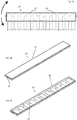
- FIG. 1 the rear of a vehicle 1 is shown. Area of the rear bumper, a sensor electrode assembly 2 according to the invention is mounted. Below the sensor electrode arrangement 2, a further sensor electrode arrangement 3 according to the invention is arranged with a vertical and horizontal offset.
- the sensor electrode assemblies 2 and 3 are connected to a control and evaluation device 4. This is arranged near the electrodes 2 and 3.
- the device 4 is in turn coupled to a central vehicle control unit 5 (see FIG. 2 ).
- the central control device 5 receives from the control and evaluation device 4 a signal for opening the tailgate, wherein the device 4 evaluates the signals of the electrodes.
- the electrodes are also charged via this control and evaluation device 4 and their capacity change in the approach of a body, such as an operator's body part is detected by charge evaluation.
- This principle of a Capacitive sensor is known in the field of automotive technology. The composite of electrodes 2, 3 and control and evaluation thus completed the detection and evaluation of signals independently and provides an opening signal.
- the sensor electrode assembly 3 is substantially parallel to the sensor electrode assembly 2.
- the configuration is such that the sensor electrode assemblies 2 and 3 have areas of changing detection sensitivity in the direction of extension of the bumper.
- the electrodes of the sensor electrode arrangements are formed in sections with different widths of the flat sides. Areas of greater width of the flat sides are conductively connected by areas of lesser width.
- the electrodes are designed as flat conductors and in this example have a uniform thickness over the entire length.
- the flat sides are aligned in the direction of the detection range of the electrodes.
- the electrode 2 is directed with its flat side to the rear, the electrode 3 down or obliquely back-down. In this example, the electrodes 2 and 3 have different distances between the more sensitive areas, and the sensitive areas are longer with electrode 2 than with electrode 3.
- the electrodes are easily adaptable to the body shape of the vehicle and e.g. attachable to the bumper with adhesives or clips.
- the sensor electrode assemblies 2 and 3 can detect both an approximation (by absolute change of the detected signal) and a movement of a body along the portions of different widths. Namely, when a body is located in front of the sensor electrode such that more area or wider portions having higher detection sensitivity are behind bodies than segments having lower detection sensitivity, the detected signal is higher than in the case where the body is positioned in front of the sensor electrode such that it is narrower or tapered Sections with lower detection sensitivity lie behind the body (see below). Does the body move? along the arrangement, this is recognizable by a signal fluctuation, in particular turning points in the signal course, which can be measured with the evaluation device.
- the sections of different widths should be tuned in their longitudinal dimension to the desired detection accuracy and the required flexibility; each have a length of 0.5cm to 30cm.
- an operator may, for example, move his lower leg in a pivoting movement under the bumper. This movement and approach is detected both by the sensor electrode 2 and by the sensor electrode 3, wherein the capacitance change is repeated in time, e.g. with a capacity determination every 5ms-15ms, queried and the change is evaluated.
- an opening command is only generated by the control device 4 if the sensor electrode arrangements 2, 3 do not register a transverse movement, which is above a permissible threshold, in the case of a time query. Namely, only a straight, directed to the vehicle gesture as opening command to be interpreted. Accordingly, the entirety of the detected signals is evaluated to allow a safe interpretation of an opening gesture.
- FIG. 3A shows a first embodiment of a sensor electrode 20 according to the invention.
- an elongated stamped metallic electrode 25 having wider (a) and narrower (b) portions has been formed by an extrusion process and encased in a flexible plastic material 30. It is formed with respect to the environment isolated strip 20, which deform and attach with a flat side to the inside of a bumper.
- this particular embodiment has by the displacement of the web, which connects the wide electrode areas, relative to the central axis a preferred bending direction. In the direction of the longer arrow greater deformation is possible as in the direction of the shorter arrow, since in bending deformations, the adjacent spread areas approach.
- the strip electrode is of course perpendicular to the flat sides facing away from each other (ie perpendicular to the paper plane in the Figure 3a ) Also bendable, in these directions, the electrode does not oppose the deformation anyway large forces.
- the metallic electrode 25 itself is led out on the sides of the plastic material 30 for contacting (see FIG. 3b ).
- any geometry of the electrode are possible, it is not necessary to form angular contours.
- wave-like electrode boundaries or curved electrode boundaries of any type can be selected as long as the electrode sections have a smaller width and a greater width.
- FIG. 3b the strip with the sensor electrode is shown schematically.
- an adhesive or adhesive tape on one side of the electrode assembly a problem-free attachment to the inside of the vehicle is possible because a flat and accessible insulating sheathing surface is available for attachment.
- FIG. 3C The location of the conductive electrode core in the cladding is in FIG. 3C again shown schematically.
- FIG. 4a shows a development of the above-described electrode shape.
- the flexible plastic sheath 40 is notched in the regions (b) of tapered electrode cross-section to allow even better flexibility while forming areas for attachment of the electrode.
- the electrode can be fixed, which is simultaneously secured against longitudinal displacements. Through the recess weight is additionally reduced and by different degrees or deep notches on the opposite sides of the preferential bending direction can be identified.
- a plug contact 50 is also attached to an electrode end exiting on one side, which can be fixed, for example, by means of a crimp connection to the sensor electrode cut by an electrode roller.
- the electrode assembly is produced with a sheath as a roll, shortened to length, so that a separation takes place at a from transition and the narrow electrode piece (b-section) is removed from sheathing and crimped.
- the connector shown here has two coupled clamp connectors, in particular to allow a plug-in control.
- a connector 50 connected to the controller may check whether the connector is properly connected to the electrode by resistance control or voltage control between both contacts.
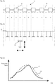
- FIG. 5a a section of a sensor electrode 10 according to the invention is shown.
- a deformable casing 11 made of an elastic material is shown in dashed lines.
- the actual sensor electrode 12 is arranged as a continuous electrical conductor.
- the sensor electrode 12 has regions a with increased width transverse to the longitudinal direction and regions b with reduced width or taper transverse to the longitudinal direction.
- the thickness of the sensor electrode that is to say the extent perpendicular to the plane of the paper, is identical over the entire electrode length in this exemplary embodiment.
- the sensor electrode 12 is created accordingly by punching or lasing of a homogeneous flat conductor material. Alternatively, a flex conductor may be used to form the electrode in the manner of the invention. At one of its ends, the sensor electrode is contacted to be connected to the controller 4.
- FIG. 5b shows along the longitudinal extent a capacitor plate assembly 14 as a model concept, which has interconnected electrically connected capacitor plates with different surface.
- the areas a is assigned a capacitor plate with a larger area and the areas b a capacitor plate with a smaller area.
- the representation in FIG. 5b it will be understood that capacitive coupling of a movable capacitor plate 15, which is movable toward both the fixed capacitor plates and laterally thereof, causes a capacitive change is to cause in the capacitor arrangement.
- the capacitor plate 15 stands for a body part of an operator, z. B. the lower leg, which approximates the electrode assembly 10 and the capacitor plate assembly 14.
- the capacitor plate 15 moves along the longitudinal direction of the electrode, it temporarily faces a smaller area capacitor (in a portion b) or a larger area plate (in section a).
- the capacitor plate 15 moves across the opposite capacitor arrays across from a large area capacitor plate over a smaller area capacitor plate to a large area capacitor plate (ie, from region a over region b to the next region a),
- the signal ie the capacity of a maximum above a minimum will rise again to a maximum.
- a transverse movement to be filtered out often overlaps an approach to or away from the electrode. Recognizable is such a transverse movement in the electrode according to the invention by viewing the waveform.
- FIG. 5c an exemplary waveform.
- the dashed lines shown waveform 17 shows a running exclusively on the sensor electrode in a vertical manner towards movement and return movement, the capacitance change increases to a maximum value (at maximum approximation) and then drops again. If this movement is superimposed on the electrode to form a transverse movement, then a signal curve 18 (shown here in a normalized manner) results, which has a turning point in the signal curve, more precisely in the signal rise itself. This inflection point results from the fact that the movement of the lower leg of a user takes place in such a way that the body is present at different times in different proportions in the respective sections a or b, ie it moves transversely to the electrode arrangement.
- the actuation kick if it is even a targeted attempt at actuation, is carried out laterally.
- the transverse recognition can be detected by means of the electrode formed according to the invention.
- the signal sequence can be discarded as a non-targeted movement.
- further criteria such as absolute signal strength, extreme values, etc., can be taken into account. It is essential that the arrangement according to the invention allows such a differentiated evaluation at all.
Description
Die Erfindung betrifft eine kapazitive Sensoranordnung mit einer Sensorelektrode, mit deren Hilfe das Eindringen eines Objekts in einen Raum vor der Sensorelektrode erfasst wird. Eine mit der Sensorelektrode gekoppelte Steuer- und Auswerteschaltung erfasst eine Änderung der Kapazität der Sensorelektrode gegenüber einem Referenzpotential, indem sie die Sensorelektrode mit einer vorgegebenen Frequenz periodisch auf- und entlädt und wenigstens einen Parameter eines vom periodischen Laden und Entladen der Sensorelektrode abhängigen Strom- oder Spannungsverlaufs zur Erfassung der Kapazitätsänderung auswertet. Die Sensorelektrode reagiert dabei auf Annäherungen bzw. Berührungen von Objekten durch eine Kapazitätsänderung des aus der Sensorelektrode und dem Objekt gebildeten Kondensators. Dies lässt sich im Kern darauf zurückführen, dass die Kapazität eines Kondensators von seinem Plattenabstand abhängt. Im Regelfall erhöht sich dessen Kapazität je näher das Objekt der Sensorelektrode kommt.The invention relates to a capacitive sensor arrangement with a sensor electrode, with the aid of which the penetration of an object into a space in front of the sensor electrode is detected. A control and evaluation circuit coupled to the sensor electrode detects a change in the capacitance of the sensor electrode relative to a reference potential by periodically charging and discharging the sensor electrode at a predetermined frequency and at least one parameter of a current or voltage curve dependent on the periodic charging and discharging of the sensor electrode evaluates for recording the capacity change. The sensor electrode responds to approaches or contact of objects by a change in capacitance of the capacitor formed from the sensor electrode and the object. This can essentially be attributed to the fact that the capacitance of a capacitor depends on its plate spacing. As a rule, its capacity increases the closer the object of the sensor electrode comes.
Eine kapazitive Sensoranordnung mit einer Sensorelektrode, mit deren Hilfe die Annäherung eines Objekts erfasst werden soll, und mit einer mit der Sensorelektrode gekoppelten Steuer- und Auswerteschaltung, die eine Änderung der Kapazität der Sensorelektrode gegenüber Masse erfasst, indem sie die Sensorelektrode mit einer vorgegebenen Frequenz periodisch wiederholt mit einer Betriebsspannung koppelt und wenigstens einen Parameter eines vom periodischen Laden und Entladen der Sensorelektrode abhängigen Strom- oder Spannungsverlaufs zur Erfassung der Kapazitätsänderung auswertet, ist beispielsweise aus dem
Aus der
Die
Bei kapazitiven Sensoren werden Kapazitätsänderungen auch als Variationen der Auflade- und/oder Entladezeit der Kapazität einer Sensorelektrode ermittelt. Beispielsweise arbeitet der Sensor nach dem Ladungstransferprinzip. Eine Auswerteelektronik nach dem Ladungstransferprinzip benötigt dabei wenigstens einen Referenzkondensator welcher turnusmäßig aufgeladen wird, wobei die Aufladezeit bestimmt wird und als Referenzzeitspanne für die Auswertung von Annäherungen oder Berührungen eines Objektes verwendet wird. Es werden also Änderungen der Aufladezeit des Referenzkondensators ausgewertet, die durch Annäherungen eines Objektes an die Sensorelektrode modifiziert werden.In capacitive sensors capacitance changes are also determined as variations in the charging and / or discharging time of the capacitance of a sensor electrode. For example, the sensor works according to the charge transfer principle. An evaluation according to the charge transfer principle requires at least one reference capacitor which is charged at regular intervals, the charging time is determined and is used as a reference period for the evaluation of approximations or touches of an object. Thus, changes in the charging time of the reference capacitor are evaluated, which are modified by approximations of an object to the sensor electrode.
Derartige Sensorelektroden können verwendet werden, um eine Tür oder Klappe eines Kraftfahrzeugs, z.B. die Heckklappe zu betätigen. Dazu können Sensorelektroden verwendet werden, welche die Annäherung eines Körperteils, z.B. eine Schwenkbewegung eines Beines unter den Stoßfänger, detektieren und in ein Kommando zum Öffnen oder Schließen der Heckklappe an eine Steuereinrichtung im Kraftfahrzeug weiterleiten. Es sind auch Sensorelektroden mit Flachbandkabel bekannt, z.B. aus der
Ein Problem mit den bekannten Einrichtungen besteht darin, dass die Sensorelektroden an eine Vielzahl von FahrzeugGeometrien anzupassen sind. Die Elektroden müssen jedoch jederzeit in möglichst geringem Abstand zu dem Detektionsbereich angeordnet werden und außerdem eine möglichst hohe Sensitivität aufweisen.A problem with the known devices is that the sensor electrodes are adapted to a variety of vehicle geometries. However, the electrodes must be arranged at any distance as close to the detection area and also have the highest possible sensitivity.
Aufgabe der Erfindung ist es daher, eine hinsichtlich der Flexibilität optimierte Sensoranordnung bereitzustellen, welche die Fehlerfassungen von Betätigungsanforderungen reduziert und welche raumsparend und flexibel am Fahrzeug anzubringen ist.The object of the invention is therefore to provide an optimized in terms of flexibility sensor arrangement, which reduces the error detections of actuation requirements and which is space-saving and flexible to install on the vehicle.
Erfindungsgemäß wird diese Aufgabe durch eine kapazitive Sensoranordnung mit den Merkmalen des Anspruchs 1 gelöst.According to the invention, this object is achieved by a capacitive sensor arrangement having the features of claim 1.
Die erfindungsgemäße Sensoranordnung zur Erfassung von Bewegungsgesten an einem Kraftfahrzeug hat wenigstens eine kapazitive Sensorelektrode und wenigstens eine mit der Sensorelektrode gekoppelte Steuer- und Auswerteeinrichtung, welche eine Änderung der Kapazität der Sensorelektrode erfasst. Die Sensorelektrode ist als langgestreckte Flachelektrode ausgebildet, wobei sich in Längsrichtung erste, breitere Elektrodenabschnitte mit einer ersten Flächenbreite mit zweiten, weniger sensitiven Abschnitten einer zweiten, geringeren Flächenbreite abwechseln, so dass abschnittsweise durchgehend leitende, jedoch unterschiedlich sensitive Elektrodenflächen mit unterschiedlichen Abmessungen gebildet sind. Die abwechselnden Bereiche weisen paarweise einheitliche Abmessungen auf, so dass alle breiteren Abschnitte einheitlich ausgebildet sind und alle schmaleren Abschnitte einheitlich ausgebildet sind.The sensor arrangement according to the invention for detecting motion gestures on a motor vehicle has at least one capacitive sensor electrode and at least one control and evaluation device which is coupled to the sensor electrode and detects a change in the capacitance of the sensor electrode. The sensor electrode is designed as an elongated flat electrode, with longitudinal, first, broader electrode sections having a first area width alternating with second, less sensitive sections of a second, smaller areal width, so that sectionally continuous, but differently sensitive electrode areas with different dimensions are formed. The alternating areas have pairwise uniform dimensions, so that all the wider sections are formed uniformly and all the narrower sections are formed uniformly.
Die zweiten Abschnitte mit geringerer Breite weisen eine geringere Länge auf als die ersten Abschnitte.The second sections of lesser width are shorter in length than the first sections.
Die erfindungsgemäße kapazitive Sensoranordnung umfasst demnach eine sich entlang einer ersten Koordinatenlinie erstreckende erste Sensorelektrode, mit deren Hilfe das Eindringen eines Objekts in einen Raum vor der ersten Sensorelektrode erfasst werden soll. Die Koordinatenlinie ist beispielsweise eine gerade Koordinatenlinie eines kartesischen Koordinatensystems; sie kann aber auch im Raum gekrümmt sein. Zur Unterscheidung der Raumrichtungen wird im Weiteren davon ausgegangen, dass die Elektrode sich mit ihrer größten Ausdehnung, der Längserstreckung in Richtung einer z-Achse erstreckt. Die Sensorelektrode besteht aus einem elektrisch leitenden Material oder einer Kombination von elektrisch leitenden Materialien und ist als Flachelektrode ausgebildet. Dies bedeutet, dass die Elektrode in einer Raumorientierung (hier als x-Achse definiert) eine Stärke aufweist, die wenigstens eine Größenordnung geringer ist als die maximale Erstreckung in den beiden dazu senkrechten Raumrichtungen (also der z-Achse und der Y-Achse). Entsprechend dieser Definition dehnt sich die Elektrode als flächige Elektrode in der yz-Ebene aus, während sie in der x-Richtung nur geringe Dicke aufweist. Die Flachelektrode weist außerdem Bereiche unterschiedlicher Flächenausdehnung in Richtung der Längserstreckung auf. Bereiche mit eingeschnürter Flächenausdehnung wechseln sich mit Bereichen vergrößerter Flächenausdehnung ab. Die Elektrodenfläche entlang der Längserstreckung ist also in verschiedenen Abschnitten unterschiedlich.The capacitive sensor arrangement according to the invention accordingly comprises a first sensor electrode extending along a first coordinate line, with the aid of which the penetration of an object into a space in front of the first sensor electrode is to be detected. The coordinate line is, for example, a straight coordinate line of a Cartesian coordinate system; but it can also be curved in space. In order to distinguish the spatial directions, it is furthermore assumed that the electrode extends with its greatest extent, the longitudinal extent, in the direction of a z-axis. The sensor electrode consists of an electric conductive material or a combination of electrically conductive materials and is formed as a flat electrode. This means that the electrode in a spatial orientation (defined here as the x-axis) has a magnitude that is at least an order of magnitude smaller than the maximum extent in the two spatial directions perpendicular thereto (ie the z-axis and the y-axis). According to this definition, the electrode expands as a planar electrode in the yz plane, while it has only small thickness in the x direction. The flat electrode also has areas of different surface area in the direction of the longitudinal extent. Areas with constricted surface area alternate with areas of increased surface area. The electrode surface along the longitudinal extent is thus different in different sections.
Zumindest die ersten Abschnitte der Elektrode sind als integrale Leiterabschnitte ausgeführt. Die zweiten Abschnitte können, wie unten beschrieben, ebenfalls integral ausgebildet sein. Dann kann die gesamte Elektrode z.B. durch stanzen oder lasern aus einem Leiterblech gebildet sein. Die zweiten Abschnitte können jedoch auch aus anderen elektrisch leitenden Kopplungsmitteln gebildet sein (z.B. auch mehradrig).At least the first sections of the electrode are designed as integral conductor sections. The second sections may also be integrally formed as described below. Then the entire electrode may be e.g. be formed by punching or lasers from a conductor plate. However, the second portions may also be formed of other electrically conductive coupling means (e.g., multi-core).
Die Bereiche geringerer Flächenbreite, also geringerer Breite quer zur Längserstreckung, sind leichter Verformbar als die Bereiche mit größerer Flächenbreite.The areas of lesser area width, ie smaller width transversely to the longitudinal extent, are more easily deformable than the areas with a larger area width.
Mit den Vergleichsbezeichnungen "größer" und "geringer" oder "kleiner" sollen die Verhältnisse der Abmessungen untereinander bestimmt werden. Es soll also gesagt werden, dass die ersten Abschnitte breiter sind als die zweiten Abschnitte und die erste Verformbarkeit geringer ist als die zweite Verformbarkeit. Wesentlich ist, dass gezielt Bereiche mit größerer Verformbarkeit in der Flachelektrode gebildet sind, welche eine Flexibilität der Flachelektrode verbessern und die Anpassung des Elektrodenverlaufs an Fahrzeugkonturen erlaubt.With the comparison designations "larger" and "smaller" or "smaller" the proportions of the dimensions should be determined among each other. It should therefore be said that the first sections are wider than the second sections and the first deformability is less than the second deformability. It is essential that specific areas with greater deformability are formed in the flat electrode, which improve flexibility of the flat electrode and allow the adaptation of the electrode profile to vehicle contours.
Eine verformbare, flache und elektrisch isolierende Ummantelung der Sensorelektrode ist zum Umschließen der Elektrode gebildet.A deformable, flat and electrically insulating sheath of the sensor electrode is formed for enclosing the electrode.
Durch diese Bauart wird einerseits eine sehr flache und platzsparende Elektrode gebildet. Außerdem wirkt die Elektrode mit ihrer Formgebung des durchgehenden Leiters ähnlich wie eine Zusammenschaltung von Kondensatorplatten unterschiedlicher Größe. Durch die verjüngten Abschnitte (kleinere Kondensatorplatten) werden die Bereiche größerer Flächenausdehnung (größerer Kondensatorplatten) verbunden. Da die Flächenbereiche elektrisch leitend verbunden sind, findet grundsätzlich ein Potenzialausgleich auf der Elektrode und ein Ausgleich der Flächenladung statt. Entsprechend reagieren die Bereiche größerer flächiger Ausdehnung stärker als die verjüngten Bereiche auf Annäherungen.On the one hand, this type of construction forms a very flat and space-saving electrode. In addition, the electrode acts with their shape of the continuous conductor similar to an interconnection of capacitor plates of different sizes. The tapered sections (smaller capacitor plates) connect the areas of larger surface area (larger capacitor plates). Since the areas are electrically connected, there is basically an equipotential bonding on the electrode and a compensation of the surface charge. Accordingly, the areas of larger areal extent react more strongly than the tapered areas on approximations.
Durch die flächige Gestaltung wird außerdem eine optimierte Ausrichtung der Elektrode erreicht. Die Elektrode wird mit ihrer flächigen Seite in Richtung des Detektionsbereiches gerichtet. Diese Empfangsfläche oder Wirkungsfläche ist dann effektiver einsetzbar als bisherige Rundelektroden, da die Kondensatorplatte (Flachseite der Flachelektrode) auf den Detektionsbereich ausgerichtet wird.The areal design also achieves optimized alignment of the electrode. The electrode is directed with its flat side in the direction of the detection area. This receiving surface or effective area can then be used more effectively than previous round electrodes, since the capacitor plate (flat side of the flat electrode) is aligned with the detection region.
Die Gesamtsensitivität der Elektrode wird gegenüber den bisher häufig verwendeten Kabelelektroden (z.B. Koaxialkabel) verbessert, was in der flächigen Ausbildung und optimierten Orientierung begründet ist. Während herkömmliche Flachelektroden jedoch oft nicht flexibel in wenigstens einer Richtung quer zu ihrer Längserstreckung waren, ist die erfindungsgemäße Flachelektrode dank der verjüngten oder schmaleren Bereiche in ihrer Flexibilität stark verbessert.The overall sensitivity of the electrode is improved over the hitherto commonly used cable electrodes (e.g., coaxial cables), which is due to the planar design and optimized orientation. However, while conventional flat electrodes were often not flexible in at least one direction transverse to their longitudinal extension, the flat electrode according to the invention is greatly improved in flexibility due to the tapered or narrower regions.
Die breiteren Bereiche können wiederum dank der durch die schmalen Bereiche vermittelten Flexibilität breiter ausgeführt werden als bei Verwendung einer gleichförmigen Flachelektrode. Dies überkompensiert die Sensitivitätsverluste in den schmalen Bereichen. Die erfindungsgemäße Elektrode ist sowohl besonders sensitiv als auch besonders Flexibel.The wider areas, in turn, can be made wider due to the flexibility afforded by the narrow areas than when using a uniform flat electrode. This overcompensates the sensitivity losses in the narrow areas. The electrode according to the invention is both particularly sensitive and particularly flexible.
Das umgebende verformbare Material schützt vor Umwelteinflüssen und Kontakt mit elektrisch leitenden Bauteilen. Außerdem kann die Ummantelung eine Kraftverteilung bei Verformung der Elektrode bewirken, welche Knicken der Elektrode oder ungleichmäßigen Verformungen vorbeugt. Die Ummantelung kann dafür insbesondere eng an der Elektrode anliegen, was z.B. durch Umspritzen, einschrumpfen oder gemeinsames Extrudieren mit der flachen Elektrode als Seele erreicht wird. Entsprechende Verfahren und zugehörige Materialien sind in der Technik z.B. im Bereich der Türdichtungen bekannt. Hierzu wird beispielhaft auf die
Die ummantelte Elektrode ist einfach an die Einpassung in verschiedenen Kraftfahrzeugen anpassbar. Die verjüngten Bereiche lassen sich leicht Verformen und die Elektrode ist entlang einer 3D-Raumlinie im Heckbereich anzuordnen. Das verformbare Ummantelungsmaterial vollzieht die Verformungen mit, ohne zu brechen oder zu reißen.The sheathed electrode is easily adaptable to fitting in various motor vehicles. The tapered areas are easily deformed and the electrode is placed along a 3D space line in the rear area. The deformable shell material complies with the deformations without breaking or tearing.
Die erfindungsgemäße Elektrode kann als Längenhalbzeug gefertigt werden und ist danach grundsätzlich auf eine gewünschte Länge kürzbar.The electrode according to the invention can be manufactured as a semi-finished product and is then in principle be shortened to a desired length.
Um die funktionalen Vorteile der erfindungsgemäßen Elektrode zu erläutern wird davon ausgegangen, dass eine mit der Sensorelektrode gekoppelte Steuer- und Auswerteschaltung vorhanden ist. Diese erfasst eine Änderung der Kapazität der Sensorelektrode gegenüber einem Referenzpotential, indem sie die erste Sensorelektrode mit einer vorgegebenen Frequenz periodisch auf- und entlädt und wenigstens einen Parameter eines vom periodischen Laden und Entladen der ersten Sensorelektrode abhängigen Strom- oder Spannungsverlaufs zur Erfassung der Kapazitätsänderung auswertet. Das periodische Auf- und Entladen führt sie beispielsweise aus, indem sie die Sensorelektrode mit der vorgegebenen Frequenz periodisch wiederholt mit einem vorgegebenen Potential, beispielsweise dem Betriebsspannungspotenzial, koppelt. Der Spannungsverlauf kann beispielsweise der Spannungsverlauf am Anschluss der ersten Sensorelektrode sein. Der Parameter kann beispielsweise eine Spannung, die über einem Ladung ansammelnden Kondensator gemessen wird, oder eine bestimmte Anzahl von Perioden des Ladens und Entladens bis zum Überschreiten einer Schaltschwelle durch eine an der ersten Sensorelektrode gemessene Spannung sein.In order to explain the functional advantages of the electrode according to the invention, it is assumed that a control and evaluation circuit coupled to the sensor electrode is present. This detects a change in the capacitance of the sensor electrode relative to a reference potential by periodically charging and discharging the first sensor electrode at a predetermined frequency and evaluating at least one parameter of a current or voltage curve dependent on the periodic charging and discharging of the first sensor electrode for detecting the capacitance change. The periodic charging and discharging performs, for example, by the sensor electrode at the predetermined frequency periodically repeatedly coupled with a predetermined potential, for example, the operating voltage potential coupled. The voltage profile may be, for example, the voltage curve at the terminal of the first sensor electrode. The parameter may be, for example, a voltage measured across a charge accumulating capacitor or a predetermined number of periods of charging and discharging until a switching threshold is exceeded by a voltage measured at the first sensor electrode.
Die erfindungsgemäße Flachelektrode weist entlang ihrer Erstreckung Bereiche mit unterschiedlicher kapazitiver Sensitivität auf, wie oben beschrieben. Ein Körperteil, welches entlang der Sensorelektrode bewegt wird, erzeugt je nach Position entsprechend unterschiedliche Signale in der Auswerteeinrichtung. Diese Einrichtung erlaubt daher die Detektion einer Annäherung und außerdem eine Detektion einer Bewegung entlang der erfindungsgemäß geformten Elektrodenanordnung durch wiederholtes Abfragen dieser geformten Elektrodenanordnung, z.B. alle 5ms bis 15ms. Dadurch können Bewegungen, welche eine Bedienungsgeste darstellen von anderen Bewegungen sicherer unterschieden werden. Insbesondere ist zu überwachen, ob die zeitliche Folge von Kapazitätswerten charakteristische Veränderungen aufweist, z.B. Wendepunkte.The flat electrode according to the invention has areas along its extent with different capacitive sensitivity, as described above. A body part, which is moved along the sensor electrode, depending on the position generates correspondingly different signals in the evaluation. This device therefore permits the detection of an approach and, in addition, a detection of a movement along the electrode arrangement formed according to the invention by repeatedly interrogating this shaped electrode arrangement, for example every 5 ms to 15 ms. As a result, movements which represent an operating gesture can be distinguished more reliably from other movements. In particular, it is to be monitored whether the temporal sequence of capacity values has characteristic changes, eg inflection points.
Eine vorgegebene Geste eines Benutzers, z.B. ein angetäuschter Kick unter den Stossfänger, soll zu einem Öffnungs- oder Schließvorgang führen. Dazu wird die Sensorelektrode abgefragt, ob das zeitliche Signalmuster charakteristisch für eines solche Bewegung ist, im genannten Beispiel also eine Annäherung des Unterschenkels eines Benutzers detektiert und zu ansteigenden Signalwerten führt.A given gesture of a user, e.g. a fake kick under the bumper, should lead to an opening or closing process. For this purpose, the sensor electrode is queried as to whether the temporal signal pattern is characteristic of such a movement, ie, in the example mentioned, an approximation of the lower leg of a user is detected and leads to rising signal values.
Die Länge der Abschnitte verschiedener Breite ist von der Anwendung abhängig. Um die gewünschte Flexibilität sicherzustellen werden die verjüngten Bereiche, also der Abstand zwischen den breiteren Bereich zu einigen mm bis einigen cm gewählt. Um die gewünschte Flexibilität zu erreichen, sind die Bereiche mit geringerer Breite deutlich weniger lang als die Bereiche mit größerer Breite und damit höherer Sensitivität.The length of sections of different widths depends on the application. In order to ensure the desired flexibility, the tapered areas, ie the distance between the wider area to a few mm to a few cm are selected. To achieve the desired flexibility, the areas with smaller width are significantly less long than the areas with greater width and thus higher sensitivity.
Die isolierende und verformbare Ummantelung weist in einer bevorzugten Ausführungsform äußere Markierungen auf, welche die Lage der breiteren und der Verjüngten Bereiche entlang der Längserstreckung markieren. Dadurch kann die in langen Stücken produzierte Elektrode (z.B. durch einen Extrusionsvorgang) in passende Abschnitte geteilt werden. Die Bereiche geringer Breite eignen sich dabei insbesondere als Trennstellen. An diesen Trennstellen kann die Kontaktierung mit Klemmen oder gekrimpten Mitteln vorgenommen werden.In one preferred embodiment, the insulating and deformable casing has outer markings which mark the position of the wider and tapered regions along the longitudinal extent. As a result, the electrode produced in long pieces (eg by an extrusion process) can be divided into suitable sections. The areas of small width are particularly suitable as separation points. At these separation points contacting with terminals or crimped means can be made.
In diesem Zusammenhang sind bei der Sensorelektrode Bereiche erster Art mit einheitlichen Abmessungen ausgebildet, so dass alle breiteren Abschnitte einheitlich ausgebildet sind. Vorzugsweise sind auch alle schmaleren Abschnitte einheitlich ausgebildet sind. Dies ermöglicht eine Auftrennung der Elektroden in gewünschter Länge, ohne auf die konkrete Art des Breiten Abschnitts zu achten.In this connection, in the sensor electrode regions of the first type are formed with uniform dimensions, so that all the wider sections are formed uniformly. Preferably, all the narrower sections are formed uniformly. This allows a separation of the electrodes in the desired length, without paying attention to the specific nature of the wide section.
An dieser Stelle ist anzumerken, dass es bei anwendungsspezifisch gefertigten Elektroden auch sein kann, dass breitere Abschnitte verschiedener Längenabmessung realisiert werden, z.B. um die schmaleren Bereiche auf solche Abschnitte zu konzentrieren, welche bei Montage stärkste Biegungen erfahren müssen.It should be noted at this point that, with custom-made electrodes, it may also be the case that wider sections of different length dimensions are realized, e.g. to focus on the narrower areas on those sections which must undergo strongest bends during installation.
In einer Ausführungsform sind die ersten Elektrodenabschnitte aus einem anderen Material gebildet sind als die zweiten Elektrodenabschnitte. Die Wahl eines leitenden, leicht verformbaren Materials für die zweiten Elektrodenabschnitte verbessert die Flexibilität der Elektrode weiter. Da es in diesen Bereichen nur nachgeordnet auf die kapazitive Sensitivität ankommt, können die zweiten Abschnitte z.B. auch aus leitendem Kunststoff oder einem ein- oder mehradrigen Flachkabel bestehen, welches entlang einer Anordnung von breiten Abschnitten (z.B. Metallplatten) in Kontakt mit diesen gebracht wird (z.B. aufgelegt oder gelötet) und anschließend umspritzt, getaucht oder eingeschrumpft wird.In one embodiment, the first electrode sections are formed from a different material than the second electrode sections. The choice of a conductive, easily deformable material for the second electrode sections further improves the flexibility of the electrode. Since the capacitive sensitivity is only secondary in these areas, the second sections may be e.g. also be made of conductive plastic or a single or multi-core flat cable which is brought into contact (e.g., laid-up or soldered) along an array of wide sections (e.g., metal plates) and then overmolded, dipped or shrunk.
Es ist besonders vorteilhaft, wenn die Ummantelung in einigen der Abschnitte geringerer Elektrodenbreite Einschnürungen aufweist, z.B. seitliche Kerbungen oder Stanzungen. Diese Einschnürungen können vorteilhaft genutzt werden, um die länglichen Elektroden an diesen Positionen mit Haltemitteln am Fahrzeug zu befestigen (z.B. mit Halteschlaufen, Klammern, Clips). Durch die Halterung in den Einschnürungen ist die Elektrode gegen Verschiebung entlang der Längsachse gesichert. Die Einschnürungen oder Stanzungen verbessern die Flexibilität in diesen Abschnitten weiter. Die Einschnürungen können bei allen Abschnitten mit geringerer Elektrodenbreite ausgeführt sein oder auch nur bei einigen der schmaleren Elektrodenabschnitte.It is particularly advantageous if the casing has constrictions in some of the sections of smaller electrode width, for example lateral notches or punches. These constrictions can be used to advantage to secure the elongated electrodes at these positions with retaining means on the vehicle (eg with straps, clips, clips). Due to the holder in the constrictions, the electrode is secured against displacement along the longitudinal axis. The constrictions or punches further enhance the flexibility in these sections. The constrictions can occur on all sections with smaller electrode width be executed or only in some of the narrower electrode sections.
Weitere vorteilhafte und/oder bevorzugte Ausführungsformen sind in den Unteransprüchen gekennzeichnet.Further advantageous and / or preferred embodiments are characterized in the subclaims.
Die Erfindung wird nun anhand der beiliegenden Figuren näher erläutert.
-
Figur 1 zeigt die Anordnung einer Ausführungsform der erfindungsgemäßen Sensoranordnung an einem Kraftfahrzeug; -
Figur 2Figur 1 in einer schematischen Aufsicht; -
Figuren 3a-3c zeigen eine erste Ausführungsform einer erfindungsgemäßen Sensorelektrodenanordnung; -
Figuren 4a-4b zeigen eine zweite Ausführungsform einer erfindungsgemäßen Sensorelektrodenanordnung; -
Figur 5a zeigt eine erfindungsgemäße Elektrode zum Einsatz an einem Kraftfahrzeug; -
Figur 5b zeigt ein schematisches Ersatzschaltbild der Elektrode ausFigur 5a ; -
Figur 5b zeigt einen schematischen Signalverlauf bei Detektion einer Betätigungsgeste;
-
FIG. 1 shows the arrangement of an embodiment of the sensor arrangement according to the invention on a motor vehicle; -
FIG. 2 shows the arrangementFIG. 1 in a schematic plan; -
FIGS. 3a-3c show a first embodiment of a sensor electrode assembly according to the invention; -
Figures 4a-4b show a second embodiment of a sensor electrode assembly according to the invention; -
FIG. 5a shows an electrode according to the invention for use on a motor vehicle; -
FIG. 5b shows a schematic equivalent circuit diagram of the electrodeFIG. 5a ; -
FIG. 5b shows a schematic waveform upon detection of an actuation gesture;
In
Die Sensorelektrodenanordnung 3 verläuft im Wesentlichen parallel zu der Sensorelektrodenanordnung 2. Die Ausbildung ist derart, dass die Sensorelektrodenanordnungen 2 und 3 in Richtung der Erstreckung des Stoßfängers Bereiche mit wechselnder Erfassungssensitivität aufweist. Dafür sind die Elektroden der Sensorelektrodenanordnungen abschnittsweise mit verschiedener Breite der Flachseiten ausgebildet. Bereiche größerer Breite der Flachseiten werden durch Bereiche geringerer Breite leitend verbunden. Die Elektroden sind als Flachleiter ausgebildet und weisen in diesem Beispiel über die gesamte Länge eine einheitliche Dicke auf. Die flächigen Seiten sind in Richtung des Erfassungsbereiches der Elektroden ausgerichtet. Die Elektrode 2 ist mit ihrer Flachseite nach hinten, die Elektrode 3 nach unten oder schräg hinten-unten gerichtet. In diesem Beispiel weisen die Elektroden 2 und 3 unterschiedliche Abstände zwischen den sensitiveren Bereichen auf und die sensitiven Bereiche sind außerdem bei Elektrode 2 länger als bei Elektrode 3.The
Dank ihrer Flexibilität sind die Elektroden an die Karosserieform des Fahrzeuges problemlos anpassbar und z.B. innen an den Stossfänger mit Klebemitteln oder Clips befestigbar.Thanks to their flexibility, the electrodes are easily adaptable to the body shape of the vehicle and e.g. attachable to the bumper with adhesives or clips.
Die Sensorelektrodenanordnungen 2 und 3 können sowohl eine Annäherung erfassen (durch absolute Veränderung des erfassten Signals) als auch eine Bewegung eines Körpers entlang der Abschnitte unterschiedlicher Breite. Befindet nämlich ein Körper derart vor der Sensorelektrode, dass mehr Fläche oder breitere Abschnitte mit höherer Erfassungssensitivität hinter Körper liegen als Segmente mit niedrigerer Erfassungssensitivität ist das ermittelte Signal höher als in dem Fall, dass der Körper derart vor der Sensorelektrode angeordnet ist, dass schmalere oder verjüngte Abschnitte mit geringerer Erfassungssensitivität hinter Körper liegen (siehe unten). Bewegt sich der Körper entlang der Anordnung, ist dies durch eine Signalfluktuation, insbesondere Wendepunkte im Signalverlauf erkennbar, welche mit der Auswerteeinrichtung messbar sind.The
Die Abschnitte unterschiedlicher Breite sollten in ihrer Längsabmessung auf die gewünschte Erfassungsgenauigkeit und die erforderliche Flexibilität abgestimmt sein, sie können z.B. jeweils eine Länge von 0,5cm bis 30cm aufweisen.The sections of different widths should be tuned in their longitudinal dimension to the desired detection accuracy and the required flexibility; each have a length of 0.5cm to 30cm.
Bei einem Bedienerwunsch kann ein Bediener bspw. seinen Unterschenkel in einer Schwenkbewegung unter den Stossfänger bewegen. Diese Bewegung und Annäherung wird sowohl durch die Sensorelektrode 2, als auch durch die Sensorelektrode 3 erfasst, wobei die Kapazitätsänderung zeitlich wiederholt, z.B. mit einer Kapazitätsermittlung alle 5ms-15ms, abgefragt und die Veränderung ausgewertet wird.In an operator request, an operator may, for example, move his lower leg in a pivoting movement under the bumper. This movement and approach is detected both by the
Ein Öffnungskommando wird jedoch nur von der Steuereinrichtung 4 generiert, wenn die Sensorelektrodenanordnungen 2, 3 bei zeitlicher Abfrage nicht eine Querbewegung registrieren, welche oberhalb einer zulässigen Schwelle liegt. Es soll nämlich nur eine gerade, auf das Fahrzeug gerichtete Geste als Öffnungskommando interpretiert werden. Demnach wird die Gesamtheit der erfassten Signale ausgewertet, um eine sichere Interpretation einer Öffnungsgeste zu ermöglichen.However, an opening command is only generated by the
Die Streifenelektrode ist selbstverständlich senkrecht zu den einander abgewandten Flachseiten (also senkrecht zur Papierebene in der
Die metallische Elektrode 25 selbst ist an den Seiten aus dem Kunststoffmaterial 30 zur Kontaktierung herausgeführt (siehe
In
Die Lage der leitenden Elektrodenseele in der Ummantelung ist in
Wie in
In
Zur Verdeutlichung der Funktionsweise ist ein Ersatzschaltbild in
In der Praxis überlagert sich einer herauszufilternden Querbewegung oft noch eine Annäherung auf die Elektrode zu oder von dieser weg. Erkennbar wird eine solche Querbewegung bei der erfindungsgemäßen Elektrode durch Betrachtung des Signalverlaufs.In practice, a transverse movement to be filtered out often overlaps an approach to or away from the electrode. Recognizable is such a transverse movement in the electrode according to the invention by viewing the waveform.
Dazu zeigt
Claims (9)
- A sensor arrangement for capacitive detection of approaches on a motor vehicle (1), having a capacitive sensor electrode (2, 3; 25) and at least one control and evaluation device (4) coupled to the sensor electrode, which detects a change in the capacitance of the sensor electrode, the sensor electrode (2, 3; 25) being constructed as an elongated flat electrode,
first electrode sections (a) with a first surface width and first deformability alternating with second sections (b) of a second, lower surface width and second, larger deformability, in the sensor electrode (2, 3; 25) in the longitudinal direction of the sensor electrode, so that in certain sections, continuously conductive and connected, but differently deformable electrode surfaces with different dimensions are formed,
characterized
in that a deformable and electrically insulating jacket (30; 40) of the sensor electrode is constructed, wherein the sensor electrode has alternating regions with uniform dimensions in pairs, so that all wider sections are constructed uniformly and all narrower sections are constructed uniformly and wherein the second sections have a smaller length than the first sections. - The sensor arrangement according to claim 1, wherein the sensor electrode is constructed with a uniform electrode thickness along its longitudinal extent.
- The sensor arrangement according to claim 1, wherein the sensor electrode is constructed from a uniform electrode material along its longitudinal extent.
- The sensor arrangement according to claim 1, wherein the first electrode sections are formed from a different material than the second electrode sections.
- The sensor arrangement according to claim 1, wherein the entire sensor electrode is constructed integrally with first and second sections.
- The sensor arrangement according to claim 4, wherein the second electrode sections are formed from a material with a smaller deformation resistance, preferably from a conductive plastic or textile material.
- The sensor arrangement according to one of the preceding claims, wherein the jacket is formed from an elastic material and wherein markings are arranged on the jacket, which display the more sensitive and less sensitive regions of the internal electrode.
- The sensor arrangement according to one of the preceding claims, wherein the jacket of the sensor electrode has constrictions in at least a few of the second regions, which are constructed for accommodating fastening means.
- The sensor arrangement according to one of the preceding claims, wherein the connecting second electrode sections are arranged between the first electrode sections axially offset along the direction of the longitudinal extent, that is to say perpendicularly to the longitudinal extent and shifted to one of the lateral boundaries of the flat electrodes.
Applications Claiming Priority (2)
| Application Number | Priority Date | Filing Date | Title |
|---|---|---|---|
| DE102012104915A DE102012104915A1 (en) | 2012-06-06 | 2012-06-06 | Capacitive sensor arrangement for switching a door opening on a motor vehicle |
| PCT/EP2013/061082 WO2013182466A1 (en) | 2012-06-06 | 2013-05-29 | Capacitive sensor arrangement for switching a door opening on a motor vehicle |
Publications (2)
| Publication Number | Publication Date |
|---|---|
| EP2859657A1 EP2859657A1 (en) | 2015-04-15 |
| EP2859657B1 true EP2859657B1 (en) | 2019-12-11 |
Family
ID=48576396
Family Applications (1)
| Application Number | Title | Priority Date | Filing Date |
|---|---|---|---|
| EP13726749.8A Active EP2859657B1 (en) | 2012-06-06 | 2013-05-29 | Capacitive sensor arrangement for switching a door opening on a motor vehicle |
Country Status (3)
| Country | Link |
|---|---|
| EP (1) | EP2859657B1 (en) |
| DE (1) | DE102012104915A1 (en) |
| WO (1) | WO2013182466A1 (en) |
Families Citing this family (10)
| Publication number | Priority date | Publication date | Assignee | Title |
|---|---|---|---|---|
| DE102011121775B3 (en) * | 2011-12-21 | 2013-01-31 | Brose Fahrzeugteile Gmbh & Co. Kg, Hallstadt | Control system for controlling e.g. motorized side door of motor car, has distance sensors with dummy portions such that sensors comprise no sensitivity or smaller sensitivity compared to region of each sensor adjacent to dummy portions |
| DE102013110238A1 (en) * | 2013-09-17 | 2015-03-19 | Brose Fahrzeugteile Gmbh & Co. Kommanditgesellschaft, Hallstadt | Electrode strand for a capacitive sensor arrangement of a motor vehicle |
| DE102013114883A1 (en) * | 2013-12-25 | 2015-06-25 | Brose Fahrzeugteile Gmbh & Co. Kommanditgesellschaft, Hallstadt | Control system for a motor-driven closure element arrangement of a motor vehicle |
| DE102014223546A1 (en) * | 2014-11-18 | 2016-05-19 | Brose Fahrzeugteile Gmbh & Co. Kg, Hallstadt | Roll produced electrode component |
| DE102014018924B4 (en) * | 2014-12-22 | 2017-03-16 | Brose Fahrzeugteile Gmbh & Co. Kommanditgesellschaft, Bamberg | Device for the contactless actuation of an adjustable vehicle part |
| DE102014018923B4 (en) | 2014-12-22 | 2017-05-04 | Brose Fahrzeugteile Gmbh & Co. Kommanditgesellschaft, Bamberg | Device for the contactless actuation of an adjustable vehicle part |
| DE102015112589A1 (en) | 2015-07-31 | 2017-02-02 | Brose Fahrzeugteile Gmbh & Co. Kommanditgesellschaft, Bamberg | Control system for a motor-adjustable loading space device of a motor vehicle |
| DE102015119701A1 (en) | 2015-11-15 | 2017-05-18 | Brose Fahrzeugteile Gmbh & Co. Kommanditgesellschaft, Bamberg | Method for operating a capacitive sensor arrangement of a motor vehicle |
| CN110023580B (en) * | 2016-11-30 | 2022-03-22 | 株式会社有信 | Vehicle door opening and closing device |
| DE102017208791A1 (en) | 2017-05-24 | 2018-11-29 | Brose Fahrzeugteile Gmbh & Co. Kommanditgesellschaft, Bamberg | Capacitive proximity sensor |
Citations (1)
| Publication number | Priority date | Publication date | Assignee | Title |
|---|---|---|---|---|
| WO2014032988A1 (en) * | 2012-08-30 | 2014-03-06 | Huf Hülsbeck & Fürst Gmbh & Co. Kg | Safety system for a motor vehicle door, comprising at least two sensors |
Family Cites Families (6)
| Publication number | Priority date | Publication date | Assignee | Title |
|---|---|---|---|---|
| US5730165A (en) | 1995-12-26 | 1998-03-24 | Philipp; Harald | Time domain capacitive field detector |
| JP2003506671A (en) * | 1999-07-29 | 2003-02-18 | エービー・オートモティブ・エレクトロニクス・リミテッド | Capacitive sensor |
| EP1339025B1 (en) | 2002-02-20 | 2007-01-03 | Kiekert Aktiengesellschaft | Vehicle with release trigger |
| JP5283973B2 (en) | 2008-05-29 | 2013-09-04 | アスモ株式会社 | Method for manufacturing sensor support member |
| DE102010002559A1 (en) * | 2010-03-03 | 2011-09-08 | Huf Hülsbeck & Fürst Gmbh & Co. Kg | Capacitive sensor arrangement for detection of e.g. door opening of motor car, has sensing electrode arrangements formed of elongated segments which are arranged in longitudinal direction to enable different capacitive detections |
| DE102010027872A1 (en) | 2010-04-16 | 2011-10-20 | Brose Fahrzeugteile Gmbh & Co. Kommanditgesellschaft, Hallstadt | Capacitive working sensor arrangement for use as capacitive tailgate switch to receive capacitive sensor signal for opening door of car, has connector comprising positioning portion to hold cable at connector and elastic portions |
-
2012
- 2012-06-06 DE DE102012104915A patent/DE102012104915A1/en not_active Ceased
-
2013
- 2013-05-29 WO PCT/EP2013/061082 patent/WO2013182466A1/en active Application Filing
- 2013-05-29 EP EP13726749.8A patent/EP2859657B1/en active Active
Patent Citations (1)
| Publication number | Priority date | Publication date | Assignee | Title |
|---|---|---|---|---|
| WO2014032988A1 (en) * | 2012-08-30 | 2014-03-06 | Huf Hülsbeck & Fürst Gmbh & Co. Kg | Safety system for a motor vehicle door, comprising at least two sensors |
Also Published As
| Publication number | Publication date |
|---|---|
| WO2013182466A1 (en) | 2013-12-12 |
| EP2859657A1 (en) | 2015-04-15 |
| DE102012104915A1 (en) | 2013-12-12 |
Similar Documents
| Publication | Publication Date | Title |
|---|---|---|
| EP2859657B1 (en) | Capacitive sensor arrangement for switching a door opening on a motor vehicle | |
| EP2630011B1 (en) | Capacitive sensor assembly for deciding on opening a door of a vehicle | |
| EP2284999B1 (en) | Sensor module | |
| EP2859658B1 (en) | Capacitive sensor arrangement for switching a door opening on a motor vehicle | |
| DE102006006780B4 (en) | Collision detection sensor for vehicles and apparatus for evaluating obstacles using the same | |
| DE102010002559A1 (en) | Capacitive sensor arrangement for detection of e.g. door opening of motor car, has sensing electrode arrangements formed of elongated segments which are arranged in longitudinal direction to enable different capacitive detections | |
| EP2957034B1 (en) | Simplified capacitive sensor unit | |
| DE102017130379A1 (en) | Sensor device with capacitive sensor for motor vehicles | |
| EP2947773B1 (en) | Variably insertable sensor unit | |
| WO2019072854A1 (en) | Protective device for an industrial robot, and protective element for such a protective device | |
| DE102013100624A1 (en) | Impact sensor with triboelectric effect for a motor vehicle | |
| EP3309967A1 (en) | Capacitive switching device | |
| DE102014018924B4 (en) | Device for the contactless actuation of an adjustable vehicle part | |
| EP3461697A1 (en) | System and method for detecting activation | |
| DE102006047062B4 (en) | Contact sensor with two operating modes for a motor vehicle | |
| EP2602069B1 (en) | Anti-collision device | |
| EP3242400B1 (en) | Electronic sensor unit for detecting a contact-free actuation of a door or hatch on a motor vehicle | |
| EP3802219B1 (en) | Horn module for a vehicle steering wheel and assembly comprising a driver airbag module and a horn module | |
| WO2015078466A1 (en) | Sensor system for capacitive distance measurement | |
| DE102018200604A1 (en) | Impact sensor with at least two spaced apart electrodes and methods for impact detection and triggering of protective devices with such an impact sensor | |
| DE102012105363A1 (en) | Sensor arrangement for detecting movement gestures of operator at motor car, has control and evaluating device actuating time-shifted sensing electrode portion subsections and separately determining capacitance of subsections | |
| DE102022204452A1 (en) | Protective element for a protective device for an industrial robot, protective device for an industrial robot and industrial robot |
Legal Events
| Date | Code | Title | Description |
|---|---|---|---|
| PUAI | Public reference made under article 153(3) epc to a published international application that has entered the european phase |
Free format text: ORIGINAL CODE: 0009012 |
|
| 17P | Request for examination filed |
Effective date: 20150107 |
|
| AK | Designated contracting states |
Kind code of ref document: A1 Designated state(s): AL AT BE BG CH CY CZ DE DK EE ES FI FR GB GR HR HU IE IS IT LI LT LU LV MC MK MT NL NO PL PT RO RS SE SI SK SM TR |
|
| AX | Request for extension of the european patent |
Extension state: BA ME |
|
| DAX | Request for extension of the european patent (deleted) | ||
| STAA | Information on the status of an ep patent application or granted ep patent |
Free format text: STATUS: EXAMINATION IS IN PROGRESS |
|
| 17Q | First examination report despatched |
Effective date: 20171009 |
|
| GRAP | Despatch of communication of intention to grant a patent |
Free format text: ORIGINAL CODE: EPIDOSNIGR1 |
|
| STAA | Information on the status of an ep patent application or granted ep patent |
Free format text: STATUS: GRANT OF PATENT IS INTENDED |
|
| INTG | Intention to grant announced |
Effective date: 20190821 |
|
| GRAS | Grant fee paid |
Free format text: ORIGINAL CODE: EPIDOSNIGR3 |
|
| GRAA | (expected) grant |
Free format text: ORIGINAL CODE: 0009210 |
|
| STAA | Information on the status of an ep patent application or granted ep patent |
Free format text: STATUS: THE PATENT HAS BEEN GRANTED |
|
| AK | Designated contracting states |
Kind code of ref document: B1 Designated state(s): AL AT BE BG CH CY CZ DE DK EE ES FI FR GB GR HR HU IE IS IT LI LT LU LV MC MK MT NL NO PL PT RO RS SE SI SK SM TR |
|
| REG | Reference to a national code |
Ref country code: GB Ref legal event code: FG4D Free format text: NOT ENGLISH |
|
| REG | Reference to a national code |
Ref country code: CH Ref legal event code: EP |
|
| REG | Reference to a national code |
Ref country code: AT Ref legal event code: REF Ref document number: 1213201 Country of ref document: AT Kind code of ref document: T Effective date: 20191215 |
|
| REG | Reference to a national code |
Ref country code: DE Ref legal event code: R096 Ref document number: 502013014055 Country of ref document: DE |
|
| REG | Reference to a national code |
Ref country code: IE Ref legal event code: FG4D Free format text: LANGUAGE OF EP DOCUMENT: GERMAN |
|
| REG | Reference to a national code |
Ref country code: NL Ref legal event code: MP Effective date: 20191211 |
|
| REG | Reference to a national code |
Ref country code: LT Ref legal event code: MG4D |
|
| PG25 | Lapsed in a contracting state [announced via postgrant information from national office to epo] |
Ref country code: ES Free format text: LAPSE BECAUSE OF FAILURE TO SUBMIT A TRANSLATION OF THE DESCRIPTION OR TO PAY THE FEE WITHIN THE PRESCRIBED TIME-LIMIT Effective date: 20191211 Ref country code: LT Free format text: LAPSE BECAUSE OF FAILURE TO SUBMIT A TRANSLATION OF THE DESCRIPTION OR TO PAY THE FEE WITHIN THE PRESCRIBED TIME-LIMIT Effective date: 20191211 Ref country code: BG Free format text: LAPSE BECAUSE OF FAILURE TO SUBMIT A TRANSLATION OF THE DESCRIPTION OR TO PAY THE FEE WITHIN THE PRESCRIBED TIME-LIMIT Effective date: 20200311 Ref country code: FI Free format text: LAPSE BECAUSE OF FAILURE TO SUBMIT A TRANSLATION OF THE DESCRIPTION OR TO PAY THE FEE WITHIN THE PRESCRIBED TIME-LIMIT Effective date: 20191211 Ref country code: GR Free format text: LAPSE BECAUSE OF FAILURE TO SUBMIT A TRANSLATION OF THE DESCRIPTION OR TO PAY THE FEE WITHIN THE PRESCRIBED TIME-LIMIT Effective date: 20200312 Ref country code: NO Free format text: LAPSE BECAUSE OF FAILURE TO SUBMIT A TRANSLATION OF THE DESCRIPTION OR TO PAY THE FEE WITHIN THE PRESCRIBED TIME-LIMIT Effective date: 20200311 Ref country code: SE Free format text: LAPSE BECAUSE OF FAILURE TO SUBMIT A TRANSLATION OF THE DESCRIPTION OR TO PAY THE FEE WITHIN THE PRESCRIBED TIME-LIMIT Effective date: 20191211 Ref country code: LV Free format text: LAPSE BECAUSE OF FAILURE TO SUBMIT A TRANSLATION OF THE DESCRIPTION OR TO PAY THE FEE WITHIN THE PRESCRIBED TIME-LIMIT Effective date: 20191211 |
|
| PG25 | Lapsed in a contracting state [announced via postgrant information from national office to epo] |
Ref country code: RS Free format text: LAPSE BECAUSE OF FAILURE TO SUBMIT A TRANSLATION OF THE DESCRIPTION OR TO PAY THE FEE WITHIN THE PRESCRIBED TIME-LIMIT Effective date: 20191211 Ref country code: HR Free format text: LAPSE BECAUSE OF FAILURE TO SUBMIT A TRANSLATION OF THE DESCRIPTION OR TO PAY THE FEE WITHIN THE PRESCRIBED TIME-LIMIT Effective date: 20191211 |
|
| PG25 | Lapsed in a contracting state [announced via postgrant information from national office to epo] |
Ref country code: AL Free format text: LAPSE BECAUSE OF FAILURE TO SUBMIT A TRANSLATION OF THE DESCRIPTION OR TO PAY THE FEE WITHIN THE PRESCRIBED TIME-LIMIT Effective date: 20191211 |
|
| PG25 | Lapsed in a contracting state [announced via postgrant information from national office to epo] |
Ref country code: RO Free format text: LAPSE BECAUSE OF FAILURE TO SUBMIT A TRANSLATION OF THE DESCRIPTION OR TO PAY THE FEE WITHIN THE PRESCRIBED TIME-LIMIT Effective date: 20191211 Ref country code: CZ Free format text: LAPSE BECAUSE OF FAILURE TO SUBMIT A TRANSLATION OF THE DESCRIPTION OR TO PAY THE FEE WITHIN THE PRESCRIBED TIME-LIMIT Effective date: 20191211 Ref country code: PT Free format text: LAPSE BECAUSE OF FAILURE TO SUBMIT A TRANSLATION OF THE DESCRIPTION OR TO PAY THE FEE WITHIN THE PRESCRIBED TIME-LIMIT Effective date: 20200506 Ref country code: NL Free format text: LAPSE BECAUSE OF FAILURE TO SUBMIT A TRANSLATION OF THE DESCRIPTION OR TO PAY THE FEE WITHIN THE PRESCRIBED TIME-LIMIT Effective date: 20191211 Ref country code: EE Free format text: LAPSE BECAUSE OF FAILURE TO SUBMIT A TRANSLATION OF THE DESCRIPTION OR TO PAY THE FEE WITHIN THE PRESCRIBED TIME-LIMIT Effective date: 20191211 |
|
| PG25 | Lapsed in a contracting state [announced via postgrant information from national office to epo] |
Ref country code: SK Free format text: LAPSE BECAUSE OF FAILURE TO SUBMIT A TRANSLATION OF THE DESCRIPTION OR TO PAY THE FEE WITHIN THE PRESCRIBED TIME-LIMIT Effective date: 20191211 Ref country code: IS Free format text: LAPSE BECAUSE OF FAILURE TO SUBMIT A TRANSLATION OF THE DESCRIPTION OR TO PAY THE FEE WITHIN THE PRESCRIBED TIME-LIMIT Effective date: 20200411 Ref country code: SM Free format text: LAPSE BECAUSE OF FAILURE TO SUBMIT A TRANSLATION OF THE DESCRIPTION OR TO PAY THE FEE WITHIN THE PRESCRIBED TIME-LIMIT Effective date: 20191211 |
|
| REG | Reference to a national code |
Ref country code: DE Ref legal event code: R097 Ref document number: 502013014055 Country of ref document: DE |
|
| PLBE | No opposition filed within time limit |
Free format text: ORIGINAL CODE: 0009261 |
|
| STAA | Information on the status of an ep patent application or granted ep patent |
Free format text: STATUS: NO OPPOSITION FILED WITHIN TIME LIMIT |
|
| PG25 | Lapsed in a contracting state [announced via postgrant information from national office to epo] |
Ref country code: DK Free format text: LAPSE BECAUSE OF FAILURE TO SUBMIT A TRANSLATION OF THE DESCRIPTION OR TO PAY THE FEE WITHIN THE PRESCRIBED TIME-LIMIT Effective date: 20191211 |
|
| 26N | No opposition filed |
Effective date: 20200914 |
|
| PG25 | Lapsed in a contracting state [announced via postgrant information from national office to epo] |
Ref country code: SI Free format text: LAPSE BECAUSE OF FAILURE TO SUBMIT A TRANSLATION OF THE DESCRIPTION OR TO PAY THE FEE WITHIN THE PRESCRIBED TIME-LIMIT Effective date: 20191211 Ref country code: PL Free format text: LAPSE BECAUSE OF FAILURE TO SUBMIT A TRANSLATION OF THE DESCRIPTION OR TO PAY THE FEE WITHIN THE PRESCRIBED TIME-LIMIT Effective date: 20191211 |
|
| PG25 | Lapsed in a contracting state [announced via postgrant information from national office to epo] |
Ref country code: CH Free format text: LAPSE BECAUSE OF NON-PAYMENT OF DUE FEES Effective date: 20200531 Ref country code: MC Free format text: LAPSE BECAUSE OF FAILURE TO SUBMIT A TRANSLATION OF THE DESCRIPTION OR TO PAY THE FEE WITHIN THE PRESCRIBED TIME-LIMIT Effective date: 20191211 Ref country code: IT Free format text: LAPSE BECAUSE OF FAILURE TO SUBMIT A TRANSLATION OF THE DESCRIPTION OR TO PAY THE FEE WITHIN THE PRESCRIBED TIME-LIMIT Effective date: 20191211 Ref country code: LI Free format text: LAPSE BECAUSE OF NON-PAYMENT OF DUE FEES Effective date: 20200531 |
|
| REG | Reference to a national code |
Ref country code: BE Ref legal event code: MM Effective date: 20200531 |
|
| GBPC | Gb: european patent ceased through non-payment of renewal fee |
Effective date: 20200529 |
|
| PG25 | Lapsed in a contracting state [announced via postgrant information from national office to epo] |
Ref country code: LU Free format text: LAPSE BECAUSE OF NON-PAYMENT OF DUE FEES Effective date: 20200529 |
|
| PG25 | Lapsed in a contracting state [announced via postgrant information from national office to epo] |
Ref country code: GB Free format text: LAPSE BECAUSE OF NON-PAYMENT OF DUE FEES Effective date: 20200529 Ref country code: FR Free format text: LAPSE BECAUSE OF NON-PAYMENT OF DUE FEES Effective date: 20200531 Ref country code: IE Free format text: LAPSE BECAUSE OF NON-PAYMENT OF DUE FEES Effective date: 20200529 |
|
| PG25 | Lapsed in a contracting state [announced via postgrant information from national office to epo] |
Ref country code: BE Free format text: LAPSE BECAUSE OF NON-PAYMENT OF DUE FEES Effective date: 20200531 |
|
| REG | Reference to a national code |
Ref country code: AT Ref legal event code: MM01 Ref document number: 1213201 Country of ref document: AT Kind code of ref document: T Effective date: 20200529 |
|
| PG25 | Lapsed in a contracting state [announced via postgrant information from national office to epo] |
Ref country code: AT Free format text: LAPSE BECAUSE OF NON-PAYMENT OF DUE FEES Effective date: 20200529 |
|
| PG25 | Lapsed in a contracting state [announced via postgrant information from national office to epo] |
Ref country code: TR Free format text: LAPSE BECAUSE OF FAILURE TO SUBMIT A TRANSLATION OF THE DESCRIPTION OR TO PAY THE FEE WITHIN THE PRESCRIBED TIME-LIMIT Effective date: 20191211 Ref country code: MT Free format text: LAPSE BECAUSE OF FAILURE TO SUBMIT A TRANSLATION OF THE DESCRIPTION OR TO PAY THE FEE WITHIN THE PRESCRIBED TIME-LIMIT Effective date: 20191211 Ref country code: CY Free format text: LAPSE BECAUSE OF FAILURE TO SUBMIT A TRANSLATION OF THE DESCRIPTION OR TO PAY THE FEE WITHIN THE PRESCRIBED TIME-LIMIT Effective date: 20191211 |
|
| PG25 | Lapsed in a contracting state [announced via postgrant information from national office to epo] |
Ref country code: MK Free format text: LAPSE BECAUSE OF FAILURE TO SUBMIT A TRANSLATION OF THE DESCRIPTION OR TO PAY THE FEE WITHIN THE PRESCRIBED TIME-LIMIT Effective date: 20191211 |
|
| P01 | Opt-out of the competence of the unified patent court (upc) registered |
Effective date: 20230507 |
|
| PGFP | Annual fee paid to national office [announced via postgrant information from national office to epo] |
Ref country code: DE Payment date: 20230531 Year of fee payment: 11 |