EP2859548B1 - Doubly compatible lossless audio bandwidth extension - Google Patents
Doubly compatible lossless audio bandwidth extension Download PDFInfo
- Publication number
- EP2859548B1 EP2859548B1 EP13733412.4A EP13733412A EP2859548B1 EP 2859548 B1 EP2859548 B1 EP 2859548B1 EP 13733412 A EP13733412 A EP 13733412A EP 2859548 B1 EP2859548 B1 EP 2859548B1
- Authority
- EP
- European Patent Office
- Prior art keywords
- output
- signal
- lossless
- input
- decoder
- Prior art date
- Legal status (The legal status is an assumption and is not a legal conclusion. Google has not performed a legal analysis and makes no representation as to the accuracy of the status listed.)
- Active
Links
Images


Classifications
-
- G—PHYSICS
- G10—MUSICAL INSTRUMENTS; ACOUSTICS
- G10L—SPEECH ANALYSIS TECHNIQUES OR SPEECH SYNTHESIS; SPEECH RECOGNITION; SPEECH OR VOICE PROCESSING TECHNIQUES; SPEECH OR AUDIO CODING OR DECODING
- G10L19/00—Speech or audio signals analysis-synthesis techniques for redundancy reduction, e.g. in vocoders; Coding or decoding of speech or audio signals, using source filter models or psychoacoustic analysis
- G10L19/0017—Lossless audio signal coding; Perfect reconstruction of coded audio signal by transmission of coding error
-
- G—PHYSICS
- G10—MUSICAL INSTRUMENTS; ACOUSTICS
- G10L—SPEECH ANALYSIS TECHNIQUES OR SPEECH SYNTHESIS; SPEECH RECOGNITION; SPEECH OR VOICE PROCESSING TECHNIQUES; SPEECH OR AUDIO CODING OR DECODING
- G10L19/00—Speech or audio signals analysis-synthesis techniques for redundancy reduction, e.g. in vocoders; Coding or decoding of speech or audio signals, using source filter models or psychoacoustic analysis
- G10L19/04—Speech or audio signals analysis-synthesis techniques for redundancy reduction, e.g. in vocoders; Coding or decoding of speech or audio signals, using source filter models or psychoacoustic analysis using predictive techniques
- G10L19/16—Vocoder architecture
- G10L19/18—Vocoders using multiple modes
- G10L19/24—Variable rate codecs, e.g. for generating different qualities using a scalable representation such as hierarchical encoding or layered encoding
-
- G—PHYSICS
- G11—INFORMATION STORAGE
- G11B—INFORMATION STORAGE BASED ON RELATIVE MOVEMENT BETWEEN RECORD CARRIER AND TRANSDUCER
- G11B20/00—Signal processing not specific to the method of recording or reproducing; Circuits therefor
- G11B20/10—Digital recording or reproducing
- G11B20/18—Error detection or correction; Testing, e.g. of drop-outs
- G11B20/1806—Pulse code modulation systems for audio signals
Definitions
- the invention relates to digital audio signals, and particularly to lossless bandwidth extension schemes that provide compatibility with standard PCM playback.
- Lossily compressed audio is commonplace in the consumer market, but experience has led many people to be suspicious of lossily compressed audio, even of systems that claim to be 'transparent'.
- An exception is plain nonadaptive noise-shaped dithered requantisation to a constant bit depth. With proper precautions this is equivalent (according to first-order and second-order statistics of the difference between input and output) to the addition of a constant noise (see J. Vanderkooy and S. P. Lipshitz, "Digital Dither: Signal Processing with Resolution Far below the Least Significant Bit” in Proc. AES 7th Int. Conf. on Audio in Digital Times (Toronto, Ont., Canada, 1989), pp. 87-96 .), which is considered 'benign' as a result of decades of experience with both analogue and digital media.
- CD Compact disc
- PCM Pulse Code Modulation
- WO2007/128662A1 describes a method and apparatus for lossless encoding of a source signal using a lossy encoded data stream and a lossless extension data stream.
- a lossless audio encoder is adapted to receive an input digital audio signal at a first sampling rate and to generate therefrom a PCM digital audio output comprising a plurality of samples and having a second sampling rate lower than the first sampling rate, wherein:
- Standard "legacy” PCM playback equipment that was not designed for use with the invention will typically receive or play only the top 16 bits here referred to as the "more significant portions", of each sample of an audio stream sampled at the second sample rate of typically 44.1kHz or 48kHz, and will present the lossy representation to the listener with a bandwidth of approximately 0-20kHz.
- the second decoder allows an extended bandwidth to be reproduced from the same 16-bit 44.1kHz or 48kHz stream.
- the first decoder typically expects to receive a 24-bit stream, and so to have access also to the "less significant portion" of each sample, i.e. to the bits beyond the sixteenth. This additional information allows lossless recovery of an input audio signal presented at a first, higher, sampling rate such as 88kHz or 96kHz, and thereby having a wider audio bandwidth such as 0-40kHz.
- the first lossy representation is an accurate representation of the input audio signal other than the effects of time-invariant filtering, sample rate reduction and requantisation that imposes a time-invariant noise floor. If all quantisations, including those within the sample rate reduction, are performed to a constant bit depth and with appropriate dither, the "lossy" representation can be of a standard equivalent to CD quality and would have been considered “audiophile” reproduction only a few years ago. This is in contrast to traditional "lossy codecs" which dynamically adapt the spectral noise floor and sometimes the bandwidth in response to the input signal.
- the compression unit comprises a lossy compression unit having an output coupled to the lossy compressed output.
- the lossless bandsplitter is key to separate treatment of, typically, two halves of the original signal spectrum, the lower half being conveyed as PCM and the upper half being conveyed in a compressed format.
- each more significant portion comprises sixteen binary bits. In some embodiments each less significant portion comprises eight binary bits.
- the second sampling rate is one half of first sampling rate.
- Particular preferred second sampling rates include 48kHz and 44.1kHz.
- the second decoder may recover an audio bandwidth equal to the Nyquist frequency that corresponds to the first sampling rate.
- the second decoder may recover a bandwidth equal to three quarters of the Nyquist frequency that corresponds to the first sampling rate.
- the term 'Nyquist frequency' is normally understood to mean half the sampling rate of a digital system.
- the first sampling rate is 96kHz
- the second is 48kHz
- the Nyquist frequency that corresponds to the first sampling rate is also 48kHz
- the second decoder will provide lossy reproduction of signals up to that Nyquist frequency, that is 48kHz.
- An alternative configuration allows the second decoder to provide lossy reproduction up to 36kHz, the advantage being a slightly lower noise floor in the range 0-24kHz.
- the compression unit further comprises a lossless compression unit having an input coupled to the lossy compression unit and an output coupled to the touchup output.
- the lossless compressor optimises the use of the bits in the least significant units. Alternatively, if the touchup output is already in compressed or "packed" form, then the separate lossless compressor is not needed.
- the less significant portion may also be derived in dependence on low frequency output of the bandsplitter. This allows a first decoder to recover losslessly an original signal that is quantised more finely than if the low frequency output of the bandsplitter were conveyed entirely within the more significant portion.
- the low frequency output of the lossless ba/ndsplitter is coupled to a splitter having a first output coupled to the more significant portion and a second output coupled to the less significant portion.
- the splitter comprises a noise-shaping filter. The splitter will provide a quantised and preferably noise-shaped representation of the LF output of the bandsplitter to the more significant portion, while its second output allows the first decoder to restore the information that was removed by the quantisation.
- a plurality of bits within the more significant portion are derived in dependence on the output of a subtractor having a first input coupled to the low frequency output of the lossless bandsplitter and a second input coupled to the compressed output of the lossy compression unit.
- the more significant portion must contain the compressed output in order to support the operation of the second decoder; however the compressed output is a data signal not an audio signal and the purpose of the subtractor is to compensate the effect of this data signal on the audio signal recovered by legacy equipment.
- apparatus comprising a noise shaper coupled to a lossless audio encoder according to the first aspect.
- this noise shaper operates at 96kHz and it reduces the wordwidth of the input signal to the encoder in order to allow the input signal to be conveyed losslessy within the constraint of a 24-bit output word at a sampling frequency of 48kHz.
- apparatus comprising a lossless audio encoder according to the first aspect coupled to a losslessly reversible watermarking encoder providing a watermarked output, wherein the apparatus encodes in dependence on configuration parameters and the watermarking encoder buries the configuration parameters in the watermarked output for use by a decoder.
- the apparatus may further comprise a noise shaper providing a quantised signal to the input of the lossless audio encoder wherein the noise shaper quantises to a bit depth and the configuration parameters include the bit depth. Additionally, the apparatus may further comprise a chooser unit that chooses a bit depth of the quantisation in order to maximise audio quality consistent with not exceeding the information carrying capacity of the less significant portions.
- the present invention provides a system whereby a high quality wide bandwidth signal can be conveyed over a baseband PCM transmission channel, also performing well if the transmission channel only conveys the top 16 bits and further providing a reasonable rendition of bandlimited audio when an encoded stream is decoded by legacy equipment interpreting the signal as baseband PCM.
- an audio decoder adapted to receive a PCM input digital audio signal comprising a plurality of input samples at a second sampling rate and to generate therefrom an output digital audio signal having a first sampling rate higher than the second sampling rate, the decoder comprising:
- the bandjoiner and decompression unit are required in order to reverse the operations of bandsplitting and compression performed in a corresponding encoder.
- Full lossless reconstruction requires that the complete input sample be presented to the decoder, but it is also desired to support lossy reconstruction when the less significant portion is missing. For this reason the lossy input to the decompression is fed from the more significant portion of the stream, and it is also desired that the low frequency input to the bandjoiner should be substantially taken from the more significant portion, any dependence on the less significant portion serving merely to improve the resolution of the low frequency signal.
- the low frequency input of the bandjoiner is derived in dependence on all the bits contained in the more significant portion.
- the more significant portion contains bits that will be fed to the decompression unit that provides the high frequency input to the lossless bandjoiner. Therefore, it might seem natural to exclude these bits when deriving the low frequency input. These bits will affect the signal heard by the legacy listener who decodes the more significant portion in a standard PCM decoder. However, it is preferred to allow those bits to contribute to the low frequency input. An encoder is then able to compensate these bits by adjusting other bits according to the principle of "subtractive buried data", in a manner that gives results that are consistent between the decoder of the invention and a standard PCM decoder.
- the low frequency input of the bandjoiner is also dependent on the less significant portion. This allows the resolution of the signal presented to the low frequency input of the bandjoiner to be improved when the less significant portion is available to the decoder.
- the difference between the output digital audio signal and a comparison signal is spectrally shaped noise with stationary statistics, wherein the comparison signal is generated from the PCM input digital audio signal by the operations of filtering and resampling to the first sampling rate.
- the difference between the output digital audio signal and a second output signal is spectrally shaped noise with stationary statistics, wherein the second output signal is produced when the decoder is fed from a signal that is identical to the PCM input digital audio signal apart from the removal of a less significant portion from each sample
- the audio decoder is adapted to receive a signal generated by a corresponding audio encoder, wherein the output digital audio signal is an exact replica of a digital audio input signal that was presented to that corresponding audio encoder.
- the decoder is intended for use with a corresponding encoder, whose output when interpreted as a plain PCM signal can satisfy the audiophile criteria such as a noise floor that may be spectrally shaped but does not vary with time.
- the decoder performs operations of filtering, resampling and quantisation in order to generate the output signal.
- the comparison signal may be generated by mimicking the decoder's operations of filtering and resampling, but at high precision without the decoder's quantisations. The difference between the output digital signal and the comparison signal thereby isolates quantisation artefacts introduced by the decoder.
- the input to the decoder is preferably a signal that satisfies audiophile criteria
- the comparison signal should also satisfy audiophile criteria, hence the difference between the comparison signal and the output signal should contain only quantisation artefacts that satisfy audiophile criteria, and are therefore equivalent to spectrally shaped noise with stationary statistics. This could be tested either by listening or using a spectrum analyser.
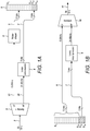
- FIGS 1A and 1B show a PCM-compatible bandwidth extension scheme similar to that proposed by Komamura in the above-cited reference.
- a bandsplitter 3 receives an original signal 2 sampled at a rate of, for example, 96kHz and thus potentially carrying information in the frequency range 0-48kHz.
- the bandsplitter uses known methods (such as Quadrature Mirror Filters) to split the signal 2 into a low-frequency (LF) signal 15 and a highfrequency (HF) signal 28, carrying respectively low frequency 0-24kHz information and high frequency 24-48kHz information; the LF and HF signals each being sampled at 48kHz, i.e. half the original sampling rate.
- LF low-frequency
- HF highfrequency
- the HF stream is then lossily compressed 4 using a known method to data stream 7 having a small number of bits, for example 1, 2 or 3 bits, while the LF stream is truncated or noise shaped 5 to a signal 6 having a larger number of bits, for example 15, 14 or 13 bits.
- Figure 1A shows an example where data stream 7 has 3 bits, while signal 6 has 13 bits. It is then straightforward to pack samples from the two streams into a single composite output stream 8 having sixteen-bit samples, with bits B 1 - B 16 , as shown in figure 1A .
- the 16-bit output stream contains samples at the lower rate, e.g. 48kHz, and can be transmitted and stored using standard consumer devices, which can also play back the stream of samples 8.
- Komamura's proposal uses ADPCM (Adaptive Differential Pulse Code Modulation) as the basis for lossy compression.
- Komamura precedes the ADPCM unit with a downsampler to provide a representation of the HF stream at a rate of 24kHz, this representation then being compressed to two bits per sample and the two bits serialised into a one-bit stream at 48kHz.
- the HF information occupies only one bit of the final 16-bit output, allowing 15 bits of LF resolution.
- Komamura's downsampler and ADPCM unit may be considered together as a lossy compression unit 4.
- a decoder is unable to provide unambiguous reconstruction of frequencies up to 48kHz: the limit is rather 36kHz.
- Figure 1B shows a decoder corresponding to figure 1A , in which the streams 6 and 7 are unpacked from the top thirteen bits B 1 -B 13 and the bottom three bits B 14 -B 16 of the transmitted stream 8, respectively.
- the decompression unit 9 substantially reverses the operation of the compression unit 4, so the bandjoiner 10 is fed with LF and HF signals that are substantially similar to the LF and HF signals 15 and 28 that were produced the bandsplitter 3.
- the bandjoiner 10 recombines these two signals to produce the output signal 11 whose audio quality in the frequency range 0-24 kHz is limited primarily by the noise-shaper 5 and in the ultrasonic range 24-48kHz by artefacts introduced by the combined actions of compression unit 4 and decompression unit 9.
- the least significant bits of the stream 8, containing the compressed HF signal 7 will also contribute to the audio output of the legacy listener's player.
- the output of an ideal compressor is noise-like, for otherwise it contains redundancy, which in principle could be removed to give improved compression. In practice it may be necessary to provide explicit scrambling to remove tonal artefacts and render the compressor's output truly noise-like. We assume in this document that the compressor 4 contains such scrambling internally if necessary to ensure that its output is composed of binary bits that are statistically independent.
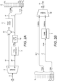
- the output of the lossy compressor 4 is a data signal, but as noted in connection with figure 1A , it is also heard as an audio signal by the legacy listener.
- This dual interpretation is recognised in figure 2A wherein the unit 12 may not exist in practice but is included to emphasise that signal 7 has a dual interpretation as a data signal and as a PCM audio signal, and then when interpreted as an audio signal it is considered as right-justified and to occupy the bottom three bits of a sixteen-bit word, that is bits B 14 through B 16 , the other bits of the word being zero.
- signal 7 interpreted as an audio signal
- the noise shaper 5 receives the signal 7 in antiphase along with the LF signal to produce a modified 13-bit signal 6' which is placed into the top thirteen bits B 1 -B 13 of the output word 8.
- the legacy listener will hear the whole of the output word 8 interpreted as a PCM audio signal, that is the sum of the signals 6' and 7.
- the legacy listener will hear the compressor signal 7 both directly via the bottom three bits of the complete word 8, and also in antiphase via the noise shaper in the top thirteen bits of the word 8, and these two presentations of the compressor signal 7 will cancel.
- the noise shaper 5 contains a 13-bit quantiser and a noise-shaping filter.
- the subtractive buried data provides subtractive dither for the 13-bit quantiser.
- Quantisation artefacts other than additive noise are now at the 16-bit level rather than the 13-bit level.
- the additive noise at the 13-bit level is shaped by the noise-shaping filter, potentially providing two or more bits of perceptual advantage, while the subtractive dither introduces 4.77dB less noise than a conventional TPDF dither.
- the perceived performance may be equivalent to that of a 16-bit system that uses TPDF dither.
- the corresponding decoder is shown in Figure 2B . It is identical to that in Figure 1B except that the LF input to the bandjoiner 10 is fed with the whole of the 16-bit composite signal rather than the top thirteen bits only. This LF signal is therefore the combination of signals 6' and 7, the same as heard by the legacy listener, and enjoys the same advantages of subtractive dither.
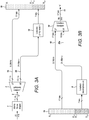
- Figure 3A and figure 3B show the encoder and decoder respectively for a simple lossless bandwidth extension system.
- the structural similarity between figures 3A and 3B and figures 1A and 1B will be obvious, but the requirement for lossless reconstruction imposes additional constraints and requires careful attention to aspects of quantisation that do not arise in the lossy case.
- a lossless system is not allowed to throw away information, so a transmission channel must have an information carrying capacity at least as large as the information in the signal to be conveyed.
- the redundancy in a 96kHz audio signal of 16 bits or higher resolution is typically about eight bits.
- a 16-bit 96kHz signal might be compressed to a data rate of eight bits per sample, and a 24-bit 96khz signal might be compressed to sixteen bits.
- a 16-bit 96kHz signal can usually be transmitted through a 16-bit 48kHz channel.
- an optimally compressed signal will appear as full scale white noise if interpreted as a PCM signal.
- a requirement for PCM compatibility forces redundancy into the PCM signal and thus requires a larger wordwidth.
- a 96kHz noise shaper 1 is shown in figure 3A , requantising a 96kHz input signal of unspecified resolution to, for example, seventeen bits, to furnish a quantised signal 2 identified as "A".
- the bandsplitter 3 is lossless and produces a low frequency output 15 also of seventeen bits and a high frequency output 28 whose resolution is indicated as eighteen bits, though it would be rare for a real audio signal to exercise all eighteen bits.
- the low frequency output thus occupies seventeen bits B 1 -B 17 of the assumed 24-bit output word 16, leaving seven bits B 18 -B 24 for a losslessly compressed version of the high frequency signal 28, produced by the lossless compressor 14.
- lossless decompression unit 9 restores signal 28a as a replica of the high frequency signal 28.
- the lossless bandjoiner 10 thus receives signals identical to the signals 15 and 28 that were produce by the lossless bandsplitter 3, and is thereby able to reconstruct the output signal 11 as a lossless replica of the signal 12.
- Signal 11 is thereby also indentified as "A”.
- the total processing indicated by figure 3A and figure 3B cannot be lossless; what is lossless is the path from the signal 2 in the encoder to the output 11 of the decoder.
- the processing provided by the encoder and decoder of figures 3A and 3B as a whole therefore delivers a noise-shaped version of the input signal, where the noise shaping 1 can be chosen to fulfil audiophile criteria including dither and with a constant bit depth.
- FIG. 3A and 3B requires a lossless band splitter 3 and joiner 10, where by "lossless” we refer to bit-exact reconstruction taking into account quantisation errors in the processing.
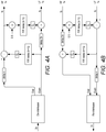
- Lossless bandsplitters and bandjoiners There are several ways to construct such lossless bandsplitters and bandjoiners, those shown in figures 4A and 4B being based on a 'lifting' principle ( Calderbank, Daubechies, Sweldon and Yeo: “Wavelet Transforms That Map Integers to Integers” Applied and Computational Harmonic Analysis, vol. 5, pp 332-369 (1998 ), especially figures 4 and 5 thereof).
- an input stream sampled at a "2x" sampling rate such as 96kHz is de-interleaved to produce separate streams of odd and even samples, each at a "1x” sampling rate such as 48kHz.
- the two streams are almost but not quite co-temporal: an original low-frequency signal in the 2x stream appears as delayed or advanced by half a 1x sample in the odd stream relative to the even stream.
- a filter of length of 10-20 taps may be reasonable to furnish an "HF" stream having good rejection of most of the bottom half of the original spectrum, i.e. of frequencies significantly below 24kHz.
- the first lifting step in figure 4A does not affect the Even sample stream, which thereby carries signals from both the top and bottom halves of the original 2x spectrum in equal measure.
- the purpose of the second lifting step is to remove original high frequency information from the Even stream by subtracting the HF output.
- a "half-sample delay" filter (actually n - 1 ⁇ 2 samples) is needed for time alignment and the multiplication by 0.5 is needed to compensate the doubled amplitude of the HF output.
- Figure 4B shows the corresponding bandjoiner, with signal flow from right to left to emphasise that the lifting steps of figure 4A are inverted in reverse order, the resulting "Odd” and “Even” at the 1x sample rate then being interleaved to reconstitute losslessly the original stream at the 2x sample rate.
- the two lifting operations will furnish a stream pair (LF, HF) in which the precise response of the LF stream near crossover may not be ideal-it may rise slightly before cutting off. If this is considered a problem, it can be avoided using three lifting operations with adjusted filter shapes.
- Each quantisation Q 1 , Q 2 should be to the original step size, for example 2 -16 if the input to the bandsplitter is a 17-bit signal occupying the signal range -1 to +1.
- the LF and HF outputs of the bandsplitter in figure 4A will then also be quantised to that original step size.
- each quantisation Q 1 , Q 2 in the decoder must behave identically to its counterpart in the encoder, for example both rounding up or both rounding down.
- HF signal contains potentially 18 bits of information
- its peak level is lower than the theoretical maximum by 35dB or more, even on 'vigorous' commercial recordings.
- Lossless compression is clearly indicated as a means to reduce the number of bits.
- Lossless compressors intrinsically produce a variable data rate, which in practice needs to be smoothed by buffering, for example, using a FIFO (First In First Out) buffer.
- the HF signals produced by bandsplitting appear typically to be more 'bursty' than standard audio signals, so buffering is even more important.
- the necessary buffers have not been shown on the diagrams here but it is assumed that such a buffer is built in to each lossless compressor and decompressor, as it is in the MLP compression system.
- FIFO buffereing introduces delay and it is necessary to add a fixed delay in any parallel signal path (such as the LF signal path) so as to maintain time alignment. Again such fixed delays have been omitted from the diagrams for clarity.
- trial encodings with different quantisation depths may be used to establish the largest quantisation depth that may be used for each item to be encoded. It can be seen that coarsening the 96kHz quantisation reduces the bitwidth required by the composite information in two ways:
- the composite information will often fit directly into 24 bits, in which case the prequantiser shown in figure 3A may be removed.
- the output 11 of the decoder of figure 3b is a lossless replica of the signal 2 in the encoder also indicated as "A".
- the listener to the decoded output 11 will enjoy the benefit of the 96kHz noise shaper, which may provide a noise density in the range 0-7kHz equivalent to a 20-bit or a 21-bit quantisation, even if quantising to only 16 bits.
- the "legacy" listener without a decoder will hear the output of the encoder interpreted as a PCM signal, thus primarily the LF output of the bandsplitter but potentially also the output of the lossless compressor interpreted as a PCM signal in the bottom bits of a 24-bit word. As already mentioned, this output should be randomised if it is not already a noiselike signal.
- the legacy listener is also exposed to any quantisation artefacts produced by the quantisers Q 1 and Q 2 in figure 4A , since these couple to the LF output of the bandsplitter.
- These artefacts may be rendered benign by the use of dither and reduced perceptually by noise-shaping, but in order to preserve lossless reconstruction the decoder of figure 4B must use identical noise shaping and identical synchronised dither in its quantisers Q 1 and Q 2 .
- the noise shapers have state variables, it may be necessary to initialise these variables identically in the decoder and encoder.
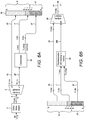
- Figure 5A shows an encoder combining the ideas illustrated in figure 3A and figure 1A , giving three listening options:
- the bandsplitter 3 may also be configured to produce the LF output 15 of thirteen bits which will fit directly into the top thirteen bits B 1 -B 13 of the output word 16.
- the HF output 28 is then lossily compressed 4 and justified 12 to bits fourteen through sixteen, B 14 -B 16 , of the output word 16.
- the more significant portion 8 of the output word 16 provides the same decoding options as did the sixteen-bit word 8 in figure 1A , as given by the two bulleted items above.
- an encoder similar to that of figure 5A could provide lossless compression 14 of the HF signal 28 to furnish a compressed signal 27 that it then places in the less significant portion 17 of the output stream 16, namely B 17 -B 24 .
- An improvement however is for the encoder to incorporate a replica 9' of the lossy decompression unit 9 that will be used in the decoder of figure 5b , and to subtract 18 the output of unit 9' from the uncompressed HF signal 28 to form a "Touchup" signal that is fed to the lossless compression unit 14.
- the subtraction 18 may reduce the data rate of the compressed Touchup signal 27 by an amount nearly equal to the data rate consumed by the lossily compressed signal 7.
- the decoder of figure 5B decompresses 19 the compressed stream 27 to furnish a replica of the Touchup signal which is then added 20 to the output of the lossy decompressor 9 in order to compensate the subtraction 18 in the encoder and furnish a replica 28a of the bandsplitter's output 28.
- the bandjoiner 10 is thus fed with signals 15 and 28a identical to the signals 15 and 28 from the bandsplitter 3, and is thus able to furnish the output 11 an exact replica "A" of the signal 2.
- the decompression, subtraction and lossless compression shown in figure 5A is in general inefficient of data rate, and a more compact representation of a touchup signal can usually be derived by adapting a lossy compressor to provide the touchup signal directly.
- Yu et al show how the lossy MPEG 4 codec may be efficiently extended to lossless operation as MPEG-SLS ( Yu, Geiger, Rahardja, Herre, Lin, and Huang: “MPEG-4 Scalable to Lossless Audio Coding", Audio Eng. Soc. 117th Convention 2004 October 28-31 San Francisco, AES preprint # 6183 ).
- the compression unit 21 may contain the internal subunits shown within the dashed box in figure 5A
- the decompression unit 22 may contain the internal subunits within the dashed box in figure 5B , but this is a suboptimal configuration.
- Figures 6A and 6B also indicate a different relationship between the quantisation depths of the HF and LF signals.
- the 96kHz quantisation is to fifteen bits, yet the LF output 15 of the lossless bandsplitter is quantised at only thirteen bits, while the HF output is quantised to eighteen bits.
- This inequality of quantisation depth can be achieved crudely by removing the two least-significant bits from the LF output of the bandsplitter of figure 5A and appending those bits to the bottom of the HF word.
- the reader is referred to section 2.3 "Different Expansion Factors for the High and Low Pass Channels" of the paper by Calderbank et al. referred to above. This change does not help the 16-bit listener, but the 24-bit listener has the benefit of an extra two bits of resolution, provided that the touchup signal derived from the longer HF word will still compress sufficiently to fit into eight bits.
- 96kHz quantisation bit depths such as 13 bits and 15 bits are for illustration only and are not intended to be limiting. The same applies to the 96kHz frequency itself.
- the 3 bits shown for the lossy compressed output is an example and compression to a smaller number of bits may be used in practice.
- the scheme of figures 6A and 6B provides excellent performance for the 24-bit listener, but for the legacy listener and for the 16-bit listener with a decoder the performance is worse than when using the encoder of figure 2A , because the scheme of figures 6A and 6B loses the advantages of noise shaping the LF signal and of using the compressed HF signal as a subtractive dither for the LF signal provide by the scheme of figures 2A and 2B .
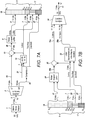
- the encoder of figure 7A restores these advantages and is designed to allow three listening possibilities for the composite word 16:
- the encoder of figure 7A becomes equivalent to the encoder of figure 2A if one deletes the less significant portion 17 of the output word and the signal paths that feed it, and replaces the noise-shaped splitter 5' by a noise shaper 5.
- the explanations that have already been given with reference to the scheme of figures 2A and 2B therefore apply to the 16-bit listener, whether legacy or using the decoder of figure 2B , so correct decoding is assured for those two cases.
- the new feature of figure 7A is the noise-shaped splitter 5' which provides a noise-shaped output 6' plus an "LSBs" signal 23 which contains the information that has been removed in the noise shaping process.
- the signal 23 is routed to some of the bits B 17 -B 20 of the less significant portion 17 of the output word 16, so that in the decoder of figure 7B , the signals 6' and 23 are both available to the noise-shaped joiner 24 which reconstructs the signal 26a as a replica of the signal.
- the signal 7 is then added 25 to the signal 26a in order to furnish signal the LF signal 15a as a replica of signal 15 in the encoder of figure 7A .
- the decompressor 22 in figure 7B functions in the same way as in figure 6B to provide the HF signal 28a, which is a lossless reconstruction of the HF signal 28.
- the bandjoiner 10 is able to reconstruct the output signal 11 as a lossless replica of signal 2.
- Figures 7A and 7B show how the system could be configured for a signal 2 having seventeen bits. For a sixteen-bit signal 2, signal 26 would also have sixteen bits and signal 23 would have three, thus allowing five bits for the "Touchup (packed)" signal 27. For an eighteen-bit signal 2, signal 26 would also have eighteen bits and signal 23 would have five, thus allowing three bits for the "Touchup (packed)” signal 27.
- the noise-shaped splitter 5' and joiner 24 may be implemented in various ways.
- Figure 8A and figure 8B providing respective examples.
- a thirteen-bit quantiser 31 is noise shaped using filter 33 whose impulse response has no zero-delay term and whose transfer function is H(z)-1.
- the joiner 24 receives both the "MSBs" 6' and the "LSBs" 23 outputs from the encoder's splitter 5'. If there were no noise-shaping the joiner would be able to recover the signal 26 by adding together the MSBs and the LSBs (suitably justified). The joiner is also able to reconstruct the input 26 if the signal modification from noise-shaping is a deterministic function of the LSBs.
- H is a finite impulse response filter with quantised coefficients.
- the output of this filter 33 should be quantised 36 to the same bitwidth as the input, i.e. 17 bits as shown, otherwise the bitwidth of the LSBs output will be increased.
- the quantisation to 17 bits should be dithered 36 to avoid undithered quantisation artefacts at the 17-bit level from being introduced into the signal heard by the legacy and 16-bit listeners. This dither must be deterministic and the dither generators 35, 35a synchronised between the encoder and decoder.
- the joiner in figure 8B is able in units 33a, 34a, 35a, 36a to produce from the "LSBs" signal 23 a replica 38a of the noise shaping modification 38 that was produced by units 33, 34, 35 and 36 in the splitter of figure 8A .
- Adder 32a adds the less significant bits 23 that were removed from the signal 37 by the quantiser 3' and adder 30a compensates the effect of the subtractor 30, thus producing a replica 26a of the signal 26.
- the noise shaped splitter 5' may be configured to receive a sixteen-bit input 26, the bottom bits of the sixteen, thereby containing only the corresponding bottom bits compressed signal 7, save for the sign reversal introduced by the subtractor 13.
- these bits are also propagated through the splitter and appear in the signal 23, save that the noise shaping modification 38 has been subtracted.
- a decoder with knowledge of the signal 38 may deduce these bits. Accordingly, these bits are effectively presented twice to the composite word, both in the signal 7 and the signal 23.
- the encoder may therefore be modified to remove the redundant bits from the signal 23, the decoder then restoring them.
- a 15-bit signal 2 there is just one least significant bit removed from the "LSBs" signal 23 by the encoder, and it can be restored as the exclusive-OR of:
- FIG. 9 shows the relevant parts of an encoder that incorporates a splitter, shown within the dashed box, which furnishes a sixteen-bit signal 29 that provides the more significant portion 8 of the output composite word directly. Analysis reveals that, if the figure 9 is substituted for the corresponding elements 12, 13 and 5' in figure 7A , there is no change to the composite word 16. The skilled person will also realise that the quantisations 1 and 31 can be replaced by quantisations whose step sizes are not necessarily related by an exact power-of-two.
- the signals are not binary but n-way choices, and for highest efficiency these signals can be entropy-coded within the composite word.
- the "MSBs" signal 6' should be represented as an integer in standard binary format and not entropy coded.
- references to 16 bits and to 24 bits in this document merely reflect wordwidths popular in current practice, and the invention can equally well be applied with different values for these longer and shorter wordwidths.
Landscapes
- Engineering & Computer Science (AREA)
- Multimedia (AREA)
- Signal Processing (AREA)
- Acoustics & Sound (AREA)
- Computational Linguistics (AREA)
- Health & Medical Sciences (AREA)
- Audiology, Speech & Language Pathology (AREA)
- Human Computer Interaction (AREA)
- Physics & Mathematics (AREA)
- Quality & Reliability (AREA)
- Compression, Expansion, Code Conversion, And Decoders (AREA)
- Reduction Or Emphasis Of Bandwidth Of Signals (AREA)
- Transmission Systems Not Characterized By The Medium Used For Transmission (AREA)
Applications Claiming Priority (2)
| Application Number | Priority Date | Filing Date | Title |
|---|---|---|---|
| GBGB1210373.5A GB201210373D0 (en) | 2012-06-12 | 2012-06-12 | Doubly compatible lossless audio sandwidth extension |
| PCT/GB2013/051548 WO2013186561A2 (en) | 2012-06-12 | 2013-06-12 | Doubly compatible lossless audio bandwidth extension |
Publications (2)
| Publication Number | Publication Date |
|---|---|
| EP2859548A2 EP2859548A2 (en) | 2015-04-15 |
| EP2859548B1 true EP2859548B1 (en) | 2018-01-31 |
Family
ID=46605804
Family Applications (1)
| Application Number | Title | Priority Date | Filing Date |
|---|---|---|---|
| EP13733412.4A Active EP2859548B1 (en) | 2012-06-12 | 2013-06-12 | Doubly compatible lossless audio bandwidth extension |
Country Status (8)
| Country | Link |
|---|---|
| US (1) | US9548055B2 (enExample) |
| EP (1) | EP2859548B1 (enExample) |
| JP (1) | JP6264699B2 (enExample) |
| KR (1) | KR102202833B1 (enExample) |
| CN (1) | CN104508740B (enExample) |
| CA (1) | CA2898923C (enExample) |
| GB (3) | GB201210373D0 (enExample) |
| WO (1) | WO2013186561A2 (enExample) |
Families Citing this family (24)
| Publication number | Priority date | Publication date | Assignee | Title |
|---|---|---|---|---|
| GB2524424B (en) * | 2011-10-24 | 2016-04-27 | Graham Craven Peter | Lossless buried data |
| GB201210373D0 (en) | 2012-06-12 | 2012-07-25 | Meridian Audio Ltd | Doubly compatible lossless audio sandwidth extension |
| EP2980795A1 (en) * | 2014-07-28 | 2016-02-03 | Fraunhofer-Gesellschaft zur Förderung der angewandten Forschung e.V. | Audio encoding and decoding using a frequency domain processor, a time domain processor and a cross processor for initialization of the time domain processor |
| GB2547877B (en) | 2015-12-21 | 2019-08-14 | Graham Craven Peter | Lossless bandsplitting and bandjoining using allpass filters |
| GB2546963B (en) * | 2015-12-23 | 2020-10-21 | Law Malcolm | Transparent lossless audio watermarking enhancement |
| CN108496221B (zh) | 2016-01-26 | 2020-01-21 | 杜比实验室特许公司 | 自适应量化 |
| US12276420B2 (en) | 2016-02-03 | 2025-04-15 | Strong Force Iot Portfolio 2016, Llc | Industrial internet of things smart heating systems and methods that produce and use hydrogen fuel |
| CN106205627B (zh) * | 2016-07-14 | 2019-10-18 | 暨南大学 | 基于边信息预测和直方图平移的数字音频可逆水印算法 |
| CN106528040A (zh) * | 2016-11-02 | 2017-03-22 | 福建星网视易信息系统有限公司 | 改进安卓设备音质的方法及装置 |
| US10354668B2 (en) * | 2017-03-22 | 2019-07-16 | Immersion Networks, Inc. | System and method for processing audio data |
| EP3483883A1 (en) | 2017-11-10 | 2019-05-15 | Fraunhofer-Gesellschaft zur Förderung der angewandten Forschung e.V. | Audio coding and decoding with selective postfiltering |
| EP3483882A1 (en) | 2017-11-10 | 2019-05-15 | Fraunhofer-Gesellschaft zur Förderung der angewandten Forschung e.V. | Controlling bandwidth in encoders and/or decoders |
| EP3483879A1 (en) | 2017-11-10 | 2019-05-15 | Fraunhofer-Gesellschaft zur Förderung der angewandten Forschung e.V. | Analysis/synthesis windowing function for modulated lapped transformation |
| EP3483886A1 (en) | 2017-11-10 | 2019-05-15 | Fraunhofer-Gesellschaft zur Förderung der angewandten Forschung e.V. | Selecting pitch lag |
| EP3483884A1 (en) | 2017-11-10 | 2019-05-15 | Fraunhofer-Gesellschaft zur Förderung der angewandten Forschung e.V. | Signal filtering |
| EP3483878A1 (en) | 2017-11-10 | 2019-05-15 | Fraunhofer-Gesellschaft zur Förderung der angewandten Forschung e.V. | Audio decoder supporting a set of different loss concealment tools |
| WO2019091576A1 (en) | 2017-11-10 | 2019-05-16 | Fraunhofer-Gesellschaft zur Förderung der angewandten Forschung e.V. | Audio encoders, audio decoders, methods and computer programs adapting an encoding and decoding of least significant bits |
| EP3483880A1 (en) | 2017-11-10 | 2019-05-15 | Fraunhofer-Gesellschaft zur Förderung der angewandten Forschung e.V. | Temporal noise shaping |
| WO2019091573A1 (en) | 2017-11-10 | 2019-05-16 | Fraunhofer-Gesellschaft zur Förderung der angewandten Forschung e.V. | Apparatus and method for encoding and decoding an audio signal using downsampling or interpolation of scale parameters |
| US20200133254A1 (en) | 2018-05-07 | 2020-04-30 | Strong Force Iot Portfolio 2016, Llc | Methods and systems for data collection, learning, and streaming of machine signals for part identification and operating characteristics determination using the industrial internet of things |
| EP3909223B1 (en) | 2019-01-13 | 2024-08-21 | Strong Force Iot Portfolio 2016, LLC | Monitoring and managing industrial settings |
| US20210127125A1 (en) * | 2019-10-23 | 2021-04-29 | Facebook Technologies, Llc | Reducing size and power consumption for frame buffers using lossy compression |
| CN115512711B (zh) * | 2021-06-22 | 2025-07-01 | 腾讯科技(深圳)有限公司 | 语音编码、语音解码方法、装置、计算机设备和存储介质 |
| CN116974453B (zh) * | 2023-09-25 | 2023-12-08 | 北京灵汐科技有限公司 | 信号处理方法、信号处理装置、信号处理器、设备及介质 |
Family Cites Families (23)
| Publication number | Priority date | Publication date | Assignee | Title |
|---|---|---|---|---|
| EP0400222A1 (en) * | 1989-06-02 | 1990-12-05 | ETAT FRANCAIS représenté par le Ministère des Postes, des Télécommunications et de l'Espace | Digital transmission system using subband coding of a digital signal |
| US5596647A (en) * | 1993-06-01 | 1997-01-21 | Matsushita Avionics Development Corporation | Integrated video and audio signal distribution system and method for use on commercial aircraft and other vehicles |
| JP3312538B2 (ja) * | 1995-08-18 | 2002-08-12 | 日本ビクター株式会社 | 音響信号処理装置 |
| US5956674A (en) * | 1995-12-01 | 1999-09-21 | Digital Theater Systems, Inc. | Multi-channel predictive subband audio coder using psychoacoustic adaptive bit allocation in frequency, time and over the multiple channels |
| US6226325B1 (en) * | 1996-03-27 | 2001-05-01 | Kabushiki Kaisha Toshiba | Digital data processing system |
| JPH09261068A (ja) * | 1996-03-27 | 1997-10-03 | Toshiba Corp | データ圧縮/復号/伝送/受信/記録/再生の方法と装置 |
| JP3405109B2 (ja) * | 1996-04-17 | 2003-05-12 | 日本ビクター株式会社 | エンコード装置、デコード装置及び記録媒体並びにデジタルオーディオ信号の再生装置 |
| KR100251453B1 (ko) * | 1997-08-26 | 2000-04-15 | 윤종용 | 고음질 오디오 부호화/복호화장치들 및 디지털다기능디스크 |
| US6226616B1 (en) * | 1999-06-21 | 2001-05-01 | Digital Theater Systems, Inc. | Sound quality of established low bit-rate audio coding systems without loss of decoder compatibility |
| JP2003280694A (ja) * | 2002-03-26 | 2003-10-02 | Nec Corp | 階層ロスレス符号化復号方法、階層ロスレス符号化方法、階層ロスレス復号方法及びその装置並びにプログラム |
| US7424434B2 (en) * | 2002-09-04 | 2008-09-09 | Microsoft Corporation | Unified lossy and lossless audio compression |
| US7395210B2 (en) * | 2002-11-21 | 2008-07-01 | Microsoft Corporation | Progressive to lossless embedded audio coder (PLEAC) with multiple factorization reversible transform |
| JP4679049B2 (ja) * | 2003-09-30 | 2011-04-27 | パナソニック株式会社 | スケーラブル復号化装置 |
| KR101207110B1 (ko) * | 2004-03-25 | 2012-12-03 | 디티에스, 인코포레이티드 | 스케일러블 무손실 비트스트림의 인코딩 방법 |
| US7392195B2 (en) * | 2004-03-25 | 2008-06-24 | Dts, Inc. | Lossless multi-channel audio codec |
| US20070078645A1 (en) * | 2005-09-30 | 2007-04-05 | Nokia Corporation | Filterbank-based processing of speech signals |
| EP1852848A1 (en) * | 2006-05-05 | 2007-11-07 | Deutsche Thomson-Brandt GmbH | Method and apparatus for lossless encoding of a source signal using a lossy encoded data stream and a lossless extension data stream |
| EP1852849A1 (en) | 2006-05-05 | 2007-11-07 | Deutsche Thomson-Brandt Gmbh | Method and apparatus for lossless encoding of a source signal, using a lossy encoded data stream and a lossless extension data stream |
| EP1883067A1 (en) * | 2006-07-24 | 2008-01-30 | Deutsche Thomson-Brandt Gmbh | Method and apparatus for lossless encoding of a source signal, using a lossy encoded data stream and a lossless extension data stream |
| PL2352147T3 (pl) * | 2008-07-11 | 2014-02-28 | Fraunhofer Ges Forschung | Urządzenie i sposób kodowania sygnału audio |
| EP2502229B1 (en) * | 2009-11-19 | 2017-08-09 | Telefonaktiebolaget LM Ericsson (publ) | Methods and arrangements for loudness and sharpness compensation in audio codecs |
| US8374858B2 (en) | 2010-03-09 | 2013-02-12 | Dts, Inc. | Scalable lossless audio codec and authoring tool |
| GB201210373D0 (en) | 2012-06-12 | 2012-07-25 | Meridian Audio Ltd | Doubly compatible lossless audio sandwidth extension |
-
2012
- 2012-06-12 GB GBGB1210373.5A patent/GB201210373D0/en not_active Ceased
-
2013
- 2013-06-12 KR KR1020157000750A patent/KR102202833B1/ko active Active
- 2013-06-12 JP JP2015516683A patent/JP6264699B2/ja active Active
- 2013-06-12 WO PCT/GB2013/051548 patent/WO2013186561A2/en not_active Ceased
- 2013-06-12 US US14/406,110 patent/US9548055B2/en active Active
- 2013-06-12 CA CA2898923A patent/CA2898923C/en active Active
- 2013-06-12 CN CN201380038662.1A patent/CN104508740B/zh active Active
- 2013-06-12 EP EP13733412.4A patent/EP2859548B1/en active Active
- 2013-06-12 GB GB1310486.4A patent/GB2503110B/en active Active
- 2013-06-13 GB GBGB1310497.1A patent/GB201310497D0/en not_active Ceased
Also Published As
| Publication number | Publication date |
|---|---|
| GB201210373D0 (en) | 2012-07-25 |
| JP6264699B2 (ja) | 2018-01-24 |
| GB2503110A (en) | 2013-12-18 |
| GB201310497D0 (en) | 2013-07-24 |
| GB2503110B (en) | 2016-06-15 |
| GB201310486D0 (en) | 2013-07-24 |
| CA2898923C (en) | 2021-03-16 |
| WO2013186561A2 (en) | 2013-12-19 |
| JP2015519615A (ja) | 2015-07-09 |
| US20150154969A1 (en) | 2015-06-04 |
| CN104508740B (zh) | 2017-08-11 |
| US9548055B2 (en) | 2017-01-17 |
| CA2898923A1 (en) | 2013-12-19 |
| WO2013186561A3 (en) | 2014-02-27 |
| EP2859548A2 (en) | 2015-04-15 |
| CN104508740A (zh) | 2015-04-08 |
| KR20150032699A (ko) | 2015-03-27 |
| KR102202833B1 (ko) | 2021-01-14 |
Similar Documents
| Publication | Publication Date | Title |
|---|---|---|
| EP2859548B1 (en) | Doubly compatible lossless audio bandwidth extension | |
| JP2015519615A5 (enExample) | ||
| ES2537820T3 (es) | Códec de audio sin pérdidas escalable y herramienta de autoría | |
| CN1639984B (zh) | 数字信号编码方法、解码方法、编码设备、解码设备 | |
| CN1809872B (zh) | 编码音频信号的设备和方法及解码已编码音频信号的设备和方法 | |
| CN1357136A (zh) | 不损失译码器兼容性下低比特率音频编码系统的音质提高 | |
| US20110224991A1 (en) | Scalable lossless audio codec and authoring tool | |
| WO2000079520A9 (en) | Improving sound quality of established low bit-rate audio coding systems without loss of decoder compatibility | |
| Craven et al. | Lossless coding for audio discs | |
| KR20050123396A (ko) | 저비트율 부호화/복호화 방법 및 장치 | |
| JP2009536363A (ja) | ロッシー符号化されたデータ・ストリームおよびロスレス拡張データ・ストリームを使用する、ソース信号のロスレス符号化を行う方法および装置 | |
| JP2007034230A (ja) | 音声符号化装置及び方法、並びに音声復号装置及び方法 | |
| CN106463126A (zh) | 基于对象的音频系统中的残差编码 | |
| KR20070037945A (ko) | 오디오 신호의 부호화/복호화 방법 및 장치 | |
| EP2228791B1 (en) | Scalable lossless audio codec and authoring tool | |
| Yang et al. | A lossless audio compression scheme with random access property | |
| Gerzon et al. | The MLP lossless compression system | |
| WO1994018762A1 (en) | Transmission of digital data words representing a signal waveform | |
| Gerzon et al. | The MLP lossless compression system for PCM audio | |
| US20060212614A1 (en) | Cd playback augmentation for higher resolution and multi-channel sound | |
| JPH0863901A (ja) | 信号記録方法及び装置、信号再生装置、並びに記録媒体 | |
| JP2001337698A (ja) | 符号化装置および符号化方法並びに復号化装置および復号化方法 | |
| HK1156146A1 (en) | Compression of audio scale-factors by two-dimensional transformation | |
| HK1156146B (en) | Compression of audio scale-factors by two-dimensional transformation |
Legal Events
| Date | Code | Title | Description |
|---|---|---|---|
| PUAI | Public reference made under article 153(3) epc to a published international application that has entered the european phase |
Free format text: ORIGINAL CODE: 0009012 |
|
| 17P | Request for examination filed |
Effective date: 20150112 |
|
| AK | Designated contracting states |
Kind code of ref document: A2 Designated state(s): AL AT BE BG CH CY CZ DE DK EE ES FI FR GB GR HR HU IE IS IT LI LT LU LV MC MK MT NL NO PL PT RO RS SE SI SK SM TR |
|
| AX | Request for extension of the european patent |
Extension state: BA ME |
|
| DAX | Request for extension of the european patent (deleted) | ||
| 17Q | First examination report despatched |
Effective date: 20161011 |
|
| GRAP | Despatch of communication of intention to grant a patent |
Free format text: ORIGINAL CODE: EPIDOSNIGR1 |
|
| INTG | Intention to grant announced |
Effective date: 20170714 |
|
| GRAJ | Information related to disapproval of communication of intention to grant by the applicant or resumption of examination proceedings by the epo deleted |
Free format text: ORIGINAL CODE: EPIDOSDIGR1 |
|
| GRAR | Information related to intention to grant a patent recorded |
Free format text: ORIGINAL CODE: EPIDOSNIGR71 |
|
| GRAS | Grant fee paid |
Free format text: ORIGINAL CODE: EPIDOSNIGR3 |
|
| GRAA | (expected) grant |
Free format text: ORIGINAL CODE: 0009210 |
|
| INTC | Intention to grant announced (deleted) | ||
| INTG | Intention to grant announced |
Effective date: 20171214 |
|
| AK | Designated contracting states |
Kind code of ref document: B1 Designated state(s): AL AT BE BG CH CY CZ DE DK EE ES FI FR GB GR HR HU IE IS IT LI LT LU LV MC MK MT NL NO PL PT RO RS SE SI SK SM TR |
|
| REG | Reference to a national code |
Ref country code: GB Ref legal event code: FG4D Ref country code: CH Ref legal event code: EP |
|
| REG | Reference to a national code |
Ref country code: AT Ref legal event code: REF Ref document number: 968028 Country of ref document: AT Kind code of ref document: T Effective date: 20180215 |
|
| REG | Reference to a national code |
Ref country code: IE Ref legal event code: FG4D |
|
| REG | Reference to a national code |
Ref country code: DE Ref legal event code: R096 Ref document number: 602013032602 Country of ref document: DE |
|
| REG | Reference to a national code |
Ref country code: NL Ref legal event code: FP |
|
| REG | Reference to a national code |
Ref country code: FR Ref legal event code: PLFP Year of fee payment: 6 |
|
| REG | Reference to a national code |
Ref country code: CH Ref legal event code: PCOW Free format text: NEW ADDRESS: 29 HILLS ROAD STEYNING, WEST SUSSEX BN44 3QG (GB) $ MERIDIAN AUDIO LIMITED, LATHAM ROAD, HUNTINGDON, CAMBRIDGESHIRE PE29 6YE (GB) $ CRAVEN, PETER G., THE KEEP MIDHURST ROAD HASLEMERE, SURREY GU27 2PT (GB) |
|
| RIN2 | Information on inventor provided after grant (corrected) |
Inventor name: LAW, MALCOLM Inventor name: CRAVEN, PETER GRAHAM Inventor name: STUART, JOHN ROBERT |
|
| RAP2 | Party data changed (patent owner data changed or rights of a patent transferred) |
Owner name: CRAVEN, PETER G. Owner name: LAW, MALCOLM Owner name: MERIDIAN AUDIO LIMITED |
|
| REG | Reference to a national code |
Ref country code: LT Ref legal event code: MG4D |
|
| REG | Reference to a national code |
Ref country code: AT Ref legal event code: MK05 Ref document number: 968028 Country of ref document: AT Kind code of ref document: T Effective date: 20180131 |
|
| PG25 | Lapsed in a contracting state [announced via postgrant information from national office to epo] |
Ref country code: NO Free format text: LAPSE BECAUSE OF FAILURE TO SUBMIT A TRANSLATION OF THE DESCRIPTION OR TO PAY THE FEE WITHIN THE PRESCRIBED TIME-LIMIT Effective date: 20180430 Ref country code: ES Free format text: LAPSE BECAUSE OF FAILURE TO SUBMIT A TRANSLATION OF THE DESCRIPTION OR TO PAY THE FEE WITHIN THE PRESCRIBED TIME-LIMIT Effective date: 20180131 Ref country code: LT Free format text: LAPSE BECAUSE OF FAILURE TO SUBMIT A TRANSLATION OF THE DESCRIPTION OR TO PAY THE FEE WITHIN THE PRESCRIBED TIME-LIMIT Effective date: 20180131 Ref country code: FI Free format text: LAPSE BECAUSE OF FAILURE TO SUBMIT A TRANSLATION OF THE DESCRIPTION OR TO PAY THE FEE WITHIN THE PRESCRIBED TIME-LIMIT Effective date: 20180131 Ref country code: HR Free format text: LAPSE BECAUSE OF FAILURE TO SUBMIT A TRANSLATION OF THE DESCRIPTION OR TO PAY THE FEE WITHIN THE PRESCRIBED TIME-LIMIT Effective date: 20180131 |
|
| PG25 | Lapsed in a contracting state [announced via postgrant information from national office to epo] |
Ref country code: IS Free format text: LAPSE BECAUSE OF FAILURE TO SUBMIT A TRANSLATION OF THE DESCRIPTION OR TO PAY THE FEE WITHIN THE PRESCRIBED TIME-LIMIT Effective date: 20180531 Ref country code: AT Free format text: LAPSE BECAUSE OF FAILURE TO SUBMIT A TRANSLATION OF THE DESCRIPTION OR TO PAY THE FEE WITHIN THE PRESCRIBED TIME-LIMIT Effective date: 20180131 Ref country code: RS Free format text: LAPSE BECAUSE OF FAILURE TO SUBMIT A TRANSLATION OF THE DESCRIPTION OR TO PAY THE FEE WITHIN THE PRESCRIBED TIME-LIMIT Effective date: 20180131 Ref country code: PL Free format text: LAPSE BECAUSE OF FAILURE TO SUBMIT A TRANSLATION OF THE DESCRIPTION OR TO PAY THE FEE WITHIN THE PRESCRIBED TIME-LIMIT Effective date: 20180131 Ref country code: SE Free format text: LAPSE BECAUSE OF FAILURE TO SUBMIT A TRANSLATION OF THE DESCRIPTION OR TO PAY THE FEE WITHIN THE PRESCRIBED TIME-LIMIT Effective date: 20180131 Ref country code: GR Free format text: LAPSE BECAUSE OF FAILURE TO SUBMIT A TRANSLATION OF THE DESCRIPTION OR TO PAY THE FEE WITHIN THE PRESCRIBED TIME-LIMIT Effective date: 20180501 Ref country code: BG Free format text: LAPSE BECAUSE OF FAILURE TO SUBMIT A TRANSLATION OF THE DESCRIPTION OR TO PAY THE FEE WITHIN THE PRESCRIBED TIME-LIMIT Effective date: 20180430 Ref country code: LV Free format text: LAPSE BECAUSE OF FAILURE TO SUBMIT A TRANSLATION OF THE DESCRIPTION OR TO PAY THE FEE WITHIN THE PRESCRIBED TIME-LIMIT Effective date: 20180131 |
|
| PG25 | Lapsed in a contracting state [announced via postgrant information from national office to epo] |
Ref country code: EE Free format text: LAPSE BECAUSE OF FAILURE TO SUBMIT A TRANSLATION OF THE DESCRIPTION OR TO PAY THE FEE WITHIN THE PRESCRIBED TIME-LIMIT Effective date: 20180131 Ref country code: RO Free format text: LAPSE BECAUSE OF FAILURE TO SUBMIT A TRANSLATION OF THE DESCRIPTION OR TO PAY THE FEE WITHIN THE PRESCRIBED TIME-LIMIT Effective date: 20180131 Ref country code: AL Free format text: LAPSE BECAUSE OF FAILURE TO SUBMIT A TRANSLATION OF THE DESCRIPTION OR TO PAY THE FEE WITHIN THE PRESCRIBED TIME-LIMIT Effective date: 20180131 |
|
| REG | Reference to a national code |
Ref country code: DE Ref legal event code: R097 Ref document number: 602013032602 Country of ref document: DE |
|
| PG25 | Lapsed in a contracting state [announced via postgrant information from national office to epo] |
Ref country code: SM Free format text: LAPSE BECAUSE OF FAILURE TO SUBMIT A TRANSLATION OF THE DESCRIPTION OR TO PAY THE FEE WITHIN THE PRESCRIBED TIME-LIMIT Effective date: 20180131 Ref country code: DK Free format text: LAPSE BECAUSE OF FAILURE TO SUBMIT A TRANSLATION OF THE DESCRIPTION OR TO PAY THE FEE WITHIN THE PRESCRIBED TIME-LIMIT Effective date: 20180131 Ref country code: SK Free format text: LAPSE BECAUSE OF FAILURE TO SUBMIT A TRANSLATION OF THE DESCRIPTION OR TO PAY THE FEE WITHIN THE PRESCRIBED TIME-LIMIT Effective date: 20180131 Ref country code: CZ Free format text: LAPSE BECAUSE OF FAILURE TO SUBMIT A TRANSLATION OF THE DESCRIPTION OR TO PAY THE FEE WITHIN THE PRESCRIBED TIME-LIMIT Effective date: 20180131 |
|
| PLBE | No opposition filed within time limit |
Free format text: ORIGINAL CODE: 0009261 |
|
| STAA | Information on the status of an ep patent application or granted ep patent |
Free format text: STATUS: NO OPPOSITION FILED WITHIN TIME LIMIT |
|
| 26N | No opposition filed |
Effective date: 20181102 |
|
| PG25 | Lapsed in a contracting state [announced via postgrant information from national office to epo] |
Ref country code: SI Free format text: LAPSE BECAUSE OF FAILURE TO SUBMIT A TRANSLATION OF THE DESCRIPTION OR TO PAY THE FEE WITHIN THE PRESCRIBED TIME-LIMIT Effective date: 20180131 |
|
| PG25 | Lapsed in a contracting state [announced via postgrant information from national office to epo] |
Ref country code: MC Free format text: LAPSE BECAUSE OF FAILURE TO SUBMIT A TRANSLATION OF THE DESCRIPTION OR TO PAY THE FEE WITHIN THE PRESCRIBED TIME-LIMIT Effective date: 20180131 Ref country code: LU Free format text: LAPSE BECAUSE OF NON-PAYMENT OF DUE FEES Effective date: 20180612 |
|
| PG25 | Lapsed in a contracting state [announced via postgrant information from national office to epo] |
Ref country code: MT Free format text: LAPSE BECAUSE OF NON-PAYMENT OF DUE FEES Effective date: 20180612 |
|
| PG25 | Lapsed in a contracting state [announced via postgrant information from national office to epo] |
Ref country code: TR Free format text: LAPSE BECAUSE OF FAILURE TO SUBMIT A TRANSLATION OF THE DESCRIPTION OR TO PAY THE FEE WITHIN THE PRESCRIBED TIME-LIMIT Effective date: 20180131 |
|
| PG25 | Lapsed in a contracting state [announced via postgrant information from national office to epo] |
Ref country code: PT Free format text: LAPSE BECAUSE OF FAILURE TO SUBMIT A TRANSLATION OF THE DESCRIPTION OR TO PAY THE FEE WITHIN THE PRESCRIBED TIME-LIMIT Effective date: 20180131 |
|
| PG25 | Lapsed in a contracting state [announced via postgrant information from national office to epo] |
Ref country code: HU Free format text: LAPSE BECAUSE OF FAILURE TO SUBMIT A TRANSLATION OF THE DESCRIPTION OR TO PAY THE FEE WITHIN THE PRESCRIBED TIME-LIMIT; INVALID AB INITIO Effective date: 20130612 Ref country code: CY Free format text: LAPSE BECAUSE OF FAILURE TO SUBMIT A TRANSLATION OF THE DESCRIPTION OR TO PAY THE FEE WITHIN THE PRESCRIBED TIME-LIMIT Effective date: 20180131 Ref country code: MK Free format text: LAPSE BECAUSE OF NON-PAYMENT OF DUE FEES Effective date: 20180131 |
|
| REG | Reference to a national code |
Ref country code: FR Ref legal event code: PLFP Year of fee payment: 11 |
|
| PGFP | Annual fee paid to national office [announced via postgrant information from national office to epo] |
Ref country code: NL Payment date: 20240426 Year of fee payment: 12 |
|
| PGFP | Annual fee paid to national office [announced via postgrant information from national office to epo] |
Ref country code: IE Payment date: 20240423 Year of fee payment: 12 |
|
| PGFP | Annual fee paid to national office [announced via postgrant information from national office to epo] |
Ref country code: DE Payment date: 20240416 Year of fee payment: 12 |
|
| PGFP | Annual fee paid to national office [announced via postgrant information from national office to epo] |
Ref country code: IT Payment date: 20240513 Year of fee payment: 12 Ref country code: FR Payment date: 20240422 Year of fee payment: 12 |
|
| PGFP | Annual fee paid to national office [announced via postgrant information from national office to epo] |
Ref country code: BE Payment date: 20240515 Year of fee payment: 12 |
|
| PGFP | Annual fee paid to national office [announced via postgrant information from national office to epo] |
Ref country code: CH Payment date: 20240701 Year of fee payment: 12 |
|
| PGFP | Annual fee paid to national office [announced via postgrant information from national office to epo] |
Ref country code: GB Payment date: 20250717 Year of fee payment: 13 |
|
| REG | Reference to a national code |
Ref country code: DE Ref legal event code: R119 Ref document number: 602013032602 Country of ref document: DE |
|
| REG | Reference to a national code |
Ref country code: CH Ref legal event code: H13 Free format text: ST27 STATUS EVENT CODE: U-0-0-H10-H13 (AS PROVIDED BY THE NATIONAL OFFICE) Effective date: 20260127 |
|
| REG | Reference to a national code |
Ref country code: NL Ref legal event code: MM Effective date: 20250701 |
|
| REG | Reference to a national code |
Ref country code: BE Ref legal event code: MM Effective date: 20250630 |
|
| PG25 | Lapsed in a contracting state [announced via postgrant information from national office to epo] |
Ref country code: NL Free format text: LAPSE BECAUSE OF NON-PAYMENT OF DUE FEES Effective date: 20250701 |
|
| PG25 | Lapsed in a contracting state [announced via postgrant information from national office to epo] |
Ref country code: DE Free format text: LAPSE BECAUSE OF NON-PAYMENT OF DUE FEES Effective date: 20260101 Ref country code: IE Free format text: LAPSE BECAUSE OF NON-PAYMENT OF DUE FEES Effective date: 20250612 |
|
| PG25 | Lapsed in a contracting state [announced via postgrant information from national office to epo] |
Ref country code: BE Free format text: LAPSE BECAUSE OF NON-PAYMENT OF DUE FEES Effective date: 20250630 Ref country code: IT Free format text: LAPSE BECAUSE OF NON-PAYMENT OF DUE FEES Effective date: 20250612 |
|
| PG25 | Lapsed in a contracting state [announced via postgrant information from national office to epo] |
Ref country code: FR Free format text: LAPSE BECAUSE OF NON-PAYMENT OF DUE FEES Effective date: 20250630 |
|
| PG25 | Lapsed in a contracting state [announced via postgrant information from national office to epo] |
Ref country code: CH Free format text: LAPSE BECAUSE OF NON-PAYMENT OF DUE FEES Effective date: 20250630 |