EP2858761B1 - A method for controlling a mineral material processing plant and a mineral material processing plant - Google Patents
A method for controlling a mineral material processing plant and a mineral material processing plant Download PDFInfo
- Publication number
- EP2858761B1 EP2858761B1 EP13733025.4A EP13733025A EP2858761B1 EP 2858761 B1 EP2858761 B1 EP 2858761B1 EP 13733025 A EP13733025 A EP 13733025A EP 2858761 B1 EP2858761 B1 EP 2858761B1
- Authority
- EP
- European Patent Office
- Prior art keywords
- processing plant
- mineral material
- plant
- actuators
- speed
- Prior art date
- Legal status (The legal status is an assumption and is not a legal conclusion. Google has not performed a legal analysis and makes no representation as to the accuracy of the status listed.)
- Active
Links
- 239000000463 material Substances 0.000 title claims description 65
- 238000000034 method Methods 0.000 title claims description 59
- 229910052500 inorganic mineral Inorganic materials 0.000 title claims description 48
- 239000011707 mineral Substances 0.000 title claims description 48
- 238000001514 detection method Methods 0.000 claims description 6
- 238000004590 computer program Methods 0.000 claims description 2
- 238000009826 distribution Methods 0.000 description 8
- 238000005265 energy consumption Methods 0.000 description 4
- 238000010276 construction Methods 0.000 description 2
- 238000010586 diagram Methods 0.000 description 2
- 238000004519 manufacturing process Methods 0.000 description 2
- 239000011435 rock Substances 0.000 description 2
- 239000002699 waste material Substances 0.000 description 2
- 230000005540 biological transmission Effects 0.000 description 1
- 230000000903 blocking effect Effects 0.000 description 1
- 238000001816 cooling Methods 0.000 description 1
- 230000001186 cumulative effect Effects 0.000 description 1
- 230000007423 decrease Effects 0.000 description 1
- 230000001419 dependent effect Effects 0.000 description 1
- 238000005516 engineering process Methods 0.000 description 1
- 230000007613 environmental effect Effects 0.000 description 1
- 239000012530 fluid Substances 0.000 description 1
- 239000010720 hydraulic oil Substances 0.000 description 1
- 239000000314 lubricant Substances 0.000 description 1
- 239000002184 metal Substances 0.000 description 1
- 238000012544 monitoring process Methods 0.000 description 1
- 238000011112 process operation Methods 0.000 description 1
- 230000001172 regenerating effect Effects 0.000 description 1
- 238000010257 thawing Methods 0.000 description 1
- XLYOFNOQVPJJNP-UHFFFAOYSA-N water Substances O XLYOFNOQVPJJNP-UHFFFAOYSA-N 0.000 description 1
Images


Classifications
-
- B—PERFORMING OPERATIONS; TRANSPORTING
- B02—CRUSHING, PULVERISING, OR DISINTEGRATING; PREPARATORY TREATMENT OF GRAIN FOR MILLING
- B02C—CRUSHING, PULVERISING, OR DISINTEGRATING IN GENERAL; MILLING GRAIN
- B02C25/00—Control arrangements specially adapted for crushing or disintegrating
-
- B—PERFORMING OPERATIONS; TRANSPORTING
- B07—SEPARATING SOLIDS FROM SOLIDS; SORTING
- B07B—SEPARATING SOLIDS FROM SOLIDS BY SIEVING, SCREENING, SIFTING OR BY USING GAS CURRENTS; SEPARATING BY OTHER DRY METHODS APPLICABLE TO BULK MATERIAL, e.g. LOOSE ARTICLES FIT TO BE HANDLED LIKE BULK MATERIAL
- B07B1/00—Sieving, screening, sifting, or sorting solid materials using networks, gratings, grids, or the like
- B07B1/42—Drive mechanisms, regulating or controlling devices, or balancing devices, specially adapted for screens
-
- B—PERFORMING OPERATIONS; TRANSPORTING
- B02—CRUSHING, PULVERISING, OR DISINTEGRATING; PREPARATORY TREATMENT OF GRAIN FOR MILLING
- B02C—CRUSHING, PULVERISING, OR DISINTEGRATING IN GENERAL; MILLING GRAIN
- B02C21/00—Disintegrating plant with or without drying of the material
- B02C21/02—Transportable disintegrating plant
- B02C21/026—Transportable disintegrating plant self-propelled
Definitions
- the invention relates to a method for controlling a mineral material processing plant and to a mineral material processing plant.
- the invention relates particularly, though not exclusively, to a mobile mineral material processing plant and to controlling thereof.
- Mineral material for example rock is gained from the earth for crushing by exploding or excavating.
- Mineral material can also be natural and gravel or construction waste.
- Mobile crushers and stationary crushing applications are used in crushing. An excavator or wheeled loader loads the material to be crushed into the crusher's feed hopper from where the material to be crushed may fall into the crusher or a feeder moves the rock material towards the crusher.
- a mineral material processing plant comprises one or more crushers and/or screens and possibly other apparatuses such as conveyors.
- a processing plant may be stationary or mobile. Particularly mobile processing plants are used in urban environment in handling of recyclable material such as construction waste.
- Capacity of a processing plant is aimed to be used economically fully so that the crusher is loaded continuously with a high crushing power and simultaneously the used crushing power is directed for producing the planned product distribution. Interruptions in the crushing event reduce efficiency. Also the starting of a processing plant is a time consuming task that further impedes the efficient exploitation of the plant's capacity.
- Mineral material processing plants are used also in extreme, for instance in very cold, circumstances wherein the processing plant may be required to be kept in operation also when the material to be handled is not fed into the plant.
- Different laws and administrative orders also regulate the use, starting and running of the processing plants.
- the standby mode triggering condition is a detection or a measuring information of the amount of mineral material to be processed in the processing plant.
- the standby speed is selected in accordance with the prevailing circumstances.
- the prevailing circumstances comprise weather conditions and/or an operating location.
- the feeding of mineral material into the processing plant is limited by stopping the actuators participating in the feeding or by reducing the speed thereof sufficiently.
- a command to switch back to a process mode is given to the processing plant
- the command to switch to the process mode is given by operating a switch.
- the command to switch to the process mode is given automatically after a predetermined time has elapsed from fulfilment of a process mode triggering condition.
- the said process mode triggering condition is a detection or a measuring information of the amount of mineral material to be processed in the processing plant.
- the mineral material processing plant comprises a screen.
- the mineral material processing plant is a stationary plant, a track-based plant or a wheel-based plant.
- a control system for controlling a mineral material processing plant according to claim 11.
- Fig. 1 shows a mobile track-mounted mineral material processing plant 100 according to an example embodiment of the invention, of which mineral material processing plant also terms processing plant and crushing plant are used in the following.
- the processing plant 100 comprises a body 101, a track base 102, a feeder 103 and a crusher 200 such as a cone, jaw or gyratory crusher.
- the crushing plant 100 further comprises a motor unit 104 for driving the crusher 200 and a conveyor 105 for conveying crushed material for example to a pile.
- the crusher 200 can be used for example as an intermediate or after crusher. Particularly, the crusher 200 can be used in fine crushing.
- the mobile crushing plant 100 may be movable also by other means such as by wheels, skids or legs.
- the crushing plant 100 may also be stationary.
- the type of the feeder 103 may be a vibratory feeder, or a belt or slat conveyor.
- the crushing plant 100 further comprises a control system 214 and a control unit 110 by which the crushing plant 100 can be run to a standby mode.
- the control unit 110 is for the sake of clarity shown separately from the control system 214 in Fig. 1 but the control unit 110 may be integrated to the control system 214.
- the crushing plant 100 comprises also standby operating switches 111 and 111' that are connected to the control unit 110 either wirelessly or with a fixed connection. Alternatively, there is only one operating switch. According to a preferred embodiment the operating switch 111 and 111' may be arranged so that it can be operated with either a wireless or fixed connection.
- the crushing plant 100 can automatically be run in the standby mode and from the standby mode back to a process mode by the operating switches 111 and 111' with one push or like switching of the switch.
- the control unit 110 or the control system includes an arrangement with which the crushing plant 100 can be run in the standby mode or the process mode also automatically.
- the automatic running of the processing plant 100 to the standby mode or the process mode starts according to a preferred embodiment after a predetermined time has elapsed from fulfilment of a standby mode or process mode triggering condition.
- the standby mode or the process mode triggering condition is according to a preferred embodiment a detection or a measuring information of the amount of mineral material in the processing plant 100, for example a detection that the feeding of the mineral material into the processing plant 100 is interrupted or measuring information based on which the crushing chamber of the crusher 200 is empty.
- the predetermined time may be selected by the operator or be automatically selected by the control unit. It should be appreciated that it is clear to a person skilled in the art that the automatic switching to the standby or process modes may be implemented also by a further known way or by selecting a further conventional triggering condition.
- Fig. 1b shows schematically a power distribution arrangement of a mineral material processing plant 100 according to a preferred embodiment.
- the motor 104 which may be for example a diesel or an electric motor produces operating power for the actuators, e.g. for the crusher 200, the feeder 103, the conveyor 105, the screen and the vibrating chute 130.
- Auxiliary devices such as a cooler 114 may be positioned in connection with the motor 104.
- the power distribution arrangement comprises also an arrangement 150 ensuring that substantially all selected actuators remain operating in the standby mode.
- the actuators are driven by a hydraulic system which gets its driving power from a diesel motor
- the crushing plant 100 comprises an arrangement 150 that also in the standby mode ensures distribution of hydraulic fluid flow to all selected actuators in such a proportion that the actuators remain operating with a reduced speed.
- an arrangement can be used for example a post compensated flow distribution valve arrangement.
- the actuators are operated by an electric motor or electric motors
- the crushing plant 100 includes an arrangement 150 that controls by the electric motor or electric motors the speeds of the selected actuators so that the actuators remain operating with the reduced speed.
- the actuators can be operated by a hydraulic system getting its driving power from an electric motor, or by another known power transmission arrangement.
- the power distribution arrangement of the processing plant 100 may also include other elements that are not shown in Fig. 1b or that in some embodiments the power distribution arrangement includes only part of the elements shown in the Figure. It is also clear that the amount of actuators shown in Fig. 1b is only an example and the amount and type of the actuators varies according to the configuration of the processing plant 100 depending on the situation.
- Fig. 2 shows, with reference to the rotational speed of the motor(s) 104, the operation of the actuators of a mineral material processing plant 100 according to a preferred embodiment of the invention which processing plant is controlled by a method according to a preferred embodiment of the invention.
- Fig. 2 shows using a diagram the controlling of the crushing plant 100 to the process speed after an interruption 500 in operation and the controlling of the crushing plant 100 to the process speed from a standby mode 400 according to a preferred embodiment of the invention.
- the rotational speed of the actuator or actuators is shown on the vertical axis and the time is shown on the horizontal axis of the diagram shown in Fig. 1 .
- the actuators of the crushing plant 100 are stopped and the motor 104 used for driving the plant is also stopped during the interruption in the operation at the time interval 0... T1.
- the motor 104 used for driving the plant may idle whilst, however, the actuators are stopped.
- the motor 104 is a diesel motor or an electric motor.
- each actuator must be started gradually according to a certain sequence when the crushing plant is started. Additionally, each actuator has its own rise time that is required before the actuator reaches its process speed.
- the process speed is meant the speed or function mode which the actuator has during the crushing operation of the crushing plant 100, i.e. when the crushing plant 100 handles material and in which mode the motor 104 of the crushing plant 100 is running with the process speed Rf.
- the crushing plant 100 typically includes more than one actuator and there may be 12 or more actuators depending on the configuration and the intended use of the crushing plant 100.
- Actuators belonging to the configuration of the crushing plant 100 are for example different conveyors such as a main conveyor and a side conveyor, a conveyor equipped with a magnet for separating metal, the screen, a water pump and the crusher.
- the running of the crushing plant 100 to the process speed takes a certain time depending on the configuration of the plant as can be seen on the graph 500 of Fig. 2 .
- the time T1 ...T3 required by the starting may be several minutes.
- the continuous running with the process speed increases energy consumption, noise production and exposes components of the crushing plant 100 to wear.
- the crushing plant 100 can be driven to standby mode instead of an interruption in operation.
- the standby mode is meant a mode in which substantially all selected actuators of the crushing plant 100 remain operating with a reduced standby speed, or standby mode speed, or reduced power. In the following this reduced speed is referred to as the standby speed.
- the standby speed may be different for each actuator and such a speed that each actuator remains operating.
- substantially all selected actuators remain operating with the reduced standby speed is meant here that apparatuses substantially connected with the crushing process, i.e. directly in contact with the processing of the mineral material remain mainly operating so that accelerating thereof to the process speed is speeded up.
- a part of the actuators of the crushing plant 100 are, however stopped in the standby mode, for example the feeder or the feeder conveyor may be stopped entirely in order to prevent the feeding as described hereinafter.
- some actuators for example cooling devices or pumps, must be operated with the process speed also in the standby mode.
- the motor 104 of the crushing plant 100 runs with the standby speed Rsb that can be for instance the idle speed of the motor 104 or other speed deviating therefrom and smaller than the process speed Rf.
- the crushing plant 100 may have several standby speeds deviating from each other, of which the most appropriate can be selected for example according to prevailing circumstances such as the weather condition, comprising for instance temperature, humidity and wind speed, or according to the operating location of the crushing plant.
- the desired actuators that keep operating with the standby speed may be selected by the operator or automatically in advance. In an example embodiment, the selection may also be dependent on the prevailing circumstances and the configuration of the processing plant 100.
- the feeding of the mineral material into the processing plant 100 is limited in the standby mode by stopping a feeder or a feeder conveyor or by selecting the standby speed so that the feeder or the feeder conveyor is not able to feed material into the crushing plant. Damaging or blocking of the actuators of the crushing plant 100, that could result from material ending up in the crushing plant operating with the standby speed, is prevented by limiting, or by completely eliminating, the feeding.
- the energy consumption of the crushing plant 100 is significantly smaller in the standby mode than in the process mode.
- the energy consumption may be for example 50% lower in the standby mode than in the process mode.
- the noise level of the crushing plant 100 decreases in the standby mode.
- the standby mode enables energy saving compared to continuous running with the process speed for example in very cold circumstances in which the crushing plant 100 must be kept continuously running for preventing damaging or function disruptions of the crushing plant 100.
- the standby mode ensures that the processing plant 100 remains warm in cold circumstances even with the reduced standby speed. For instance the used hydraulic oil and different lubricants can be kept in suitable operating temperature also with the standby speed. In said cold circumstances the standby mode can be utilized also in defrosting of the conveyors of the crushing plant 100.
- the lower noise level of the standby mode also enables increasing the effective operating time of the crushing plant 100 for example in circumstances in which the cumulative noise amount generated by the crushing plant 100 is limited for example according to administrative orders. Such operating situations arise increasingly for example in urban environment in crushing of recyclable material such as material of demolished buildings.
- the standby mode is also found to improve safety of the crushing plant 100.
- Moving and rotating actuators are easier to observe and thus avoid getting in contact with.
- some of the actuators of the crushing plant 100 may start suddenly if for example the acoustic signal indicating the starting was ignored, or an actuator in question starts at a late stage of a starting sequence, for example even after several minutes from the acoustic signal or giving of a starting command.
- the standby mode can also be utilized to implement certain adjustment actions of the actuators of the crushing plant 100.
- the jaws of a jaw crusher may be adjusted during the standby mode or regenerating of a possible diesel motor may be implemented during the standby mode instead of an interruption in operation.
- the position of the crushing plant 100 may be fine-tuned in the standby mode.
- Fig. 3 shows a flow chart of a method according to a preferred embodiment of the invention. Initially 300 the crushing plant 100 is run with the process speed Rf.
- the crushing plant 100 is desired to be switched to the standby mode because of insufficiency of the material to be fed or for a further reason.
- the standby mode is started in step 310 for example by operating the switch 111,111'. For example the operator monitoring the crushing plant 100 starts the standby mode. Alternatively, the standby mode may be started automatically when certain conditions are met as described hereinbefore.
- step 320 The feeding of mineral material into the crushing plant 100 is limited in step 320 in the way described hereinbefore by stopping the actuators taking care of the feeding or by reducing the speed thereof so that the material does not end up in the actuators.
- the speed of the motor 104 or motors of the processing plant 100 and following therefrom the speed of the actuators is reduced in step 330 until the desired standby mode speed Rsb is achieved 340. After that the crushing plant 100 remains operating with the reduced speed Rf.
- the standby mode is switched off in step 340 in a corresponding manner to it previously being switched on, i.e. manually or automatically, after which the speed of the motor(s) and the operating speed is increased until the process speed Rf is achieved. Thereafter the feeding of material into the crushing plant 100 is enabled again in step 380 and the operation of the crushing plant 100 continues in the process mode.
- reducing of the energy consumption and the noise production can be considered technical advantages of different embodiments of the invention.
- prolonging the lifetime of components of the mineral material processing plant can be considered a technical advantage of different embodiments of the invention.
- increasing the environmental friendliness of the mineral material processing plant can be considered a technical advantage of different embodiments of the invention.
- improving the safety of the mineral material processing plant can be considered a technical advantage of different embodiments of the invention.
- increasing the effective operating hours of the mineral material processing plant can be considered a technical advantage of different embodiments of the invention.
Description
- The invention relates to a method for controlling a mineral material processing plant and to a mineral material processing plant. The invention relates particularly, though not exclusively, to a mobile mineral material processing plant and to controlling thereof.
- Mineral material, for example rock is gained from the earth for crushing by exploding or excavating. Mineral material can also be natural and gravel or construction waste. Mobile crushers and stationary crushing applications are used in crushing. An excavator or wheeled loader loads the material to be crushed into the crusher's feed hopper from where the material to be crushed may fall into the crusher or a feeder moves the rock material towards the crusher.
- A mineral material processing plant comprises one or more crushers and/or screens and possibly other apparatuses such as conveyors. A processing plant may be stationary or mobile. Particularly mobile processing plants are used in urban environment in handling of recyclable material such as construction waste.
- Capacity of a processing plant is aimed to be used economically fully so that the crusher is loaded continuously with a high crushing power and simultaneously the used crushing power is directed for producing the planned product distribution. Interruptions in the crushing event reduce efficiency. Also the starting of a processing plant is a time consuming task that further impedes the efficient exploitation of the plant's capacity.
- Mineral material processing plants are used also in extreme, for instance in very cold, circumstances wherein the processing plant may be required to be kept in operation also when the material to be handled is not fed into the plant. Different laws and administrative orders also regulate the use, starting and running of the processing plants.
- Previous technologies related to the issues are known from publications
US2009/294560A1 andJP3967497B2 - It is an object of the invention to provide a mineral material processing plant the bringing of which into process operation is quick and safe. It is an object of the invention to provide a processing plant that can be kept in operation energy-efficiently. It is an object of the invention to enable an effective crushing or other processing time as long as possible.
- According to a first aspect of the invention there is provided a method for controlling a mineral material processing plant according to claim 1.
- Preferably the standby mode triggering condition is a detection or a measuring information of the amount of mineral material to be processed in the processing plant.
- Preferably the standby speed is selected in accordance with the prevailing circumstances.
- Preferably the prevailing circumstances comprise weather conditions and/or an operating location.
- According to the invention, the feeding of mineral material into the processing plant is limited by stopping the actuators participating in the feeding or by reducing the speed thereof sufficiently.
- In the method, preferably a command to switch back to a process mode is given to the processing plant;
- speed of the motor or motors of the processing plant is raised from the standby speed to the processing speed in response to said command to switch back to the process mode; and
- the feeding of mineral material into the processing plant is enabled.
- Preferably the command to switch to the process mode is given by operating a switch.
- Preferably the command to switch to the process mode is given automatically after a predetermined time has elapsed from fulfilment of a process mode triggering condition.
- Preferably the said process mode triggering condition is a detection or a measuring information of the amount of mineral material to be processed in the processing plant.
- According to a second aspect of the invention there is provided a mineral material processing plant according to claim 8.
- Preferably the mineral material processing plant comprises a screen.
- Preferably the mineral material processing plant is a stationary plant, a track-based plant or a wheel-based plant.
- According to a third aspect of the invention there is provided a control system for controlling a mineral material processing plant according to
claim 11. - According to a fourth aspect of the invention there is provided a computer program according to claim 12..
- Different embodiments of the present invention will be illustrated or have been illustrated only in connection with some aspects of the invention. A skilled person appreciates that any embodiment of an aspect of the invention may apply to the same aspect of the invention and other aspects alone or in combination with other embodiments as well.
- The invention will now be described, by way of example, with reference to the accompanying drawings, in which:
-
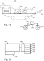
Fig. 1a shows a side view of a mineral material processing plant according to a preferred embodiment of the invention; -
Fig. 1b shows schematically a power distribution arrangement of a mineral material processing plant according to a preferred embodiment of the invention; -
Fig. 2 shows, with reference to rotational speed, the operation of actuators of a mineral material processing plant according to a preferred embodiment of the invention which processing plant is controlled by a method according to a preferred embodiment of the invention; and -
Fig. 3 shows a flow chart of a method according to a preferred embodiment of the invention. - In the following description, like numbers denote like elements. It should be appreciated that the illustrated drawings are not entirely in scale, and that the drawings mainly serve the purpose of illustrating embodiments of the invention.
-
Fig. 1 shows a mobile track-mounted mineralmaterial processing plant 100 according to an example embodiment of the invention, of which mineral material processing plant also terms processing plant and crushing plant are used in the following. Theprocessing plant 100 comprises a body 101, atrack base 102, afeeder 103 and acrusher 200 such as a cone, jaw or gyratory crusher. The crushingplant 100 further comprises amotor unit 104 for driving thecrusher 200 and aconveyor 105 for conveying crushed material for example to a pile. Thecrusher 200 can be used for example as an intermediate or after crusher. Particularly, thecrusher 200 can be used in fine crushing. The mobile crushingplant 100 may be movable also by other means such as by wheels, skids or legs. The crushingplant 100 may also be stationary. The type of thefeeder 103 may be a vibratory feeder, or a belt or slat conveyor. - The crushing
plant 100 further comprises acontrol system 214 and acontrol unit 110 by which the crushingplant 100 can be run to a standby mode. Thecontrol unit 110 is for the sake of clarity shown separately from thecontrol system 214 inFig. 1 but thecontrol unit 110 may be integrated to thecontrol system 214. The crushingplant 100 comprises alsostandby operating switches 111 and 111' that are connected to thecontrol unit 110 either wirelessly or with a fixed connection. Alternatively, there is only one operating switch. According to a preferred embodiment theoperating switch 111 and 111' may be arranged so that it can be operated with either a wireless or fixed connection. The crushingplant 100 can automatically be run in the standby mode and from the standby mode back to a process mode by theoperating switches 111 and 111' with one push or like switching of the switch. According to a preferred embodiment thecontrol unit 110 or the control system includes an arrangement with which the crushingplant 100 can be run in the standby mode or the process mode also automatically. The automatic running of theprocessing plant 100 to the standby mode or the process mode starts according to a preferred embodiment after a predetermined time has elapsed from fulfilment of a standby mode or process mode triggering condition. The standby mode or the process mode triggering condition is according to a preferred embodiment a detection or a measuring information of the amount of mineral material in theprocessing plant 100, for example a detection that the feeding of the mineral material into theprocessing plant 100 is interrupted or measuring information based on which the crushing chamber of thecrusher 200 is empty. The predetermined time may be selected by the operator or be automatically selected by the control unit. It should be appreciated that it is clear to a person skilled in the art that the automatic switching to the standby or process modes may be implemented also by a further known way or by selecting a further conventional triggering condition. -
Fig. 1b shows schematically a power distribution arrangement of a mineralmaterial processing plant 100 according to a preferred embodiment. Themotor 104 which may be for example a diesel or an electric motor produces operating power for the actuators, e.g. for thecrusher 200, thefeeder 103, theconveyor 105, the screen and the vibratingchute 130. Auxiliary devices such as a cooler 114 may be positioned in connection with themotor 104. The power distribution arrangement comprises also anarrangement 150 ensuring that substantially all selected actuators remain operating in the standby mode. According to an exemplary embodiment the actuators are driven by a hydraulic system which gets its driving power from a diesel motor, and the crushingplant 100 comprises anarrangement 150 that also in the standby mode ensures distribution of hydraulic fluid flow to all selected actuators in such a proportion that the actuators remain operating with a reduced speed. According to a preferred embodiment as such an arrangement can be used for example a post compensated flow distribution valve arrangement. According to an example embodiment the actuators are operated by an electric motor or electric motors, and the crushingplant 100 includes anarrangement 150 that controls by the electric motor or electric motors the speeds of the selected actuators so that the actuators remain operating with the reduced speed. Alternatively, the actuators can be operated by a hydraulic system getting its driving power from an electric motor, or by another known power transmission arrangement. It should be appreciated that it is clear to a person skilled in the art that the power distribution arrangement of theprocessing plant 100 may also include other elements that are not shown inFig. 1b or that in some embodiments the power distribution arrangement includes only part of the elements shown in the Figure. It is also clear that the amount of actuators shown inFig. 1b is only an example and the amount and type of the actuators varies according to the configuration of theprocessing plant 100 depending on the situation. -
Fig. 2 shows, with reference to the rotational speed of the motor(s) 104, the operation of the actuators of a mineralmaterial processing plant 100 according to a preferred embodiment of the invention which processing plant is controlled by a method according to a preferred embodiment of the invention.Fig. 2 shows using a diagram the controlling of the crushingplant 100 to the process speed after aninterruption 500 in operation and the controlling of the crushingplant 100 to the process speed from astandby mode 400 according to a preferred embodiment of the invention. The rotational speed of the actuator or actuators is shown on the vertical axis and the time is shown on the horizontal axis of the diagram shown inFig. 1 . - The actuators of the crushing
plant 100 are stopped and themotor 104 used for driving the plant is also stopped during the interruption in the operation at thetime interval 0... T1. Alternatively, themotor 104 used for driving the plant may idle whilst, however, the actuators are stopped. According to an example embodiment themotor 104 is a diesel motor or an electric motor. - The actuators must be started gradually according to a certain sequence when the crushing plant is started. Additionally, each actuator has its own rise time that is required before the actuator reaches its process speed. By the process speed is meant the speed or function mode which the actuator has during the crushing operation of the crushing
plant 100, i.e. when the crushingplant 100 handles material and in which mode themotor 104 of the crushingplant 100 is running with the process speed Rf. - Also administrative orders regulate the starting of the crushing
plant 100. Prior to starting, for example an acoustic signal must be given and a certain waiting time must be reserved before the starting of the actuators for ensuring safety. - The crushing
plant 100 typically includes more than one actuator and there may be 12 or more actuators depending on the configuration and the intended use of the crushingplant 100. Actuators belonging to the configuration of the crushingplant 100 are for example different conveyors such as a main conveyor and a side conveyor, a conveyor equipped with a magnet for separating metal, the screen, a water pump and the crusher. Subject to the amount of the actuators and the starting sequence as described hereinbefore and the matters connected therewith, the running of the crushingplant 100 to the process speed takes a certain time depending on the configuration of the plant as can be seen on thegraph 500 ofFig. 2 . The time T1 ...T3 required by the starting may be several minutes. - The time T1 ...T3 required by the starting results in the crushing
plant 100 typically being run with the process speed also when the material to be handled is not fed into the crushingplant 100, especially if the time during which no material is fed is short. The continuous running with the process speed increases energy consumption, noise production and exposes components of the crushingplant 100 to wear. - According to an embodiment of the invention the crushing
plant 100 can be driven to standby mode instead of an interruption in operation. By the standby mode is meant a mode in which substantially all selected actuators of the crushingplant 100 remain operating with a reduced standby speed, or standby mode speed, or reduced power. In the following this reduced speed is referred to as the standby speed. The standby speed may be different for each actuator and such a speed that each actuator remains operating. By the expression that substantially all selected actuators remain operating with the reduced standby speed is meant here that apparatuses substantially connected with the crushing process, i.e. directly in contact with the processing of the mineral material remain mainly operating so that accelerating thereof to the process speed is speeded up. In some example embodiments, a part of the actuators of the crushingplant 100 are, however stopped in the standby mode, for example the feeder or the feeder conveyor may be stopped entirely in order to prevent the feeding as described hereinafter. Furthermore, in some example embodiments also some actuators, for example cooling devices or pumps, must be operated with the process speed also in the standby mode. In the standby mode themotor 104 of the crushingplant 100 runs with the standby speed Rsb that can be for instance the idle speed of themotor 104 or other speed deviating therefrom and smaller than the process speed Rf. According to a preferred embodiment the crushingplant 100 may have several standby speeds deviating from each other, of which the most appropriate can be selected for example according to prevailing circumstances such as the weather condition, comprising for instance temperature, humidity and wind speed, or according to the operating location of the crushing plant. The desired actuators that keep operating with the standby speed may be selected by the operator or automatically in advance. In an example embodiment, the selection may also be dependent on the prevailing circumstances and the configuration of theprocessing plant 100. - The feeding of the mineral material into the
processing plant 100 is limited in the standby mode by stopping a feeder or a feeder conveyor or by selecting the standby speed so that the feeder or the feeder conveyor is not able to feed material into the crushing plant. Damaging or blocking of the actuators of the crushingplant 100, that could result from material ending up in the crushing plant operating with the standby speed, is prevented by limiting, or by completely eliminating, the feeding. - When the crushing
plant 100 is driven from the standby speed Rsb to the process speed Rf substantially all actuators can be accelerated simultaneously, wherethrough the process speed is reached in a significantly shorter time T1...T2 compared to the starting from an interruption in operation. The switching over from the standby speed Rsb to the process speed Rf may take for example some seconds. It is appreciated that correspondingly also switching from the process speed Rf to the standby speed Rsb requires a significantly shorter time than the switching from the process speed Rf to an interruption in operation. - The energy consumption of the crushing
plant 100 is significantly smaller in the standby mode than in the process mode. The energy consumption may be for example 50% lower in the standby mode than in the process mode. Also the noise level of the crushingplant 100 decreases in the standby mode. The standby mode enables energy saving compared to continuous running with the process speed for example in very cold circumstances in which the crushingplant 100 must be kept continuously running for preventing damaging or function disruptions of the crushingplant 100. The standby mode ensures that theprocessing plant 100 remains warm in cold circumstances even with the reduced standby speed. For instance the used hydraulic oil and different lubricants can be kept in suitable operating temperature also with the standby speed. In said cold circumstances the standby mode can be utilized also in defrosting of the conveyors of the crushingplant 100. - The lower noise level of the standby mode also enables increasing the effective operating time of the crushing
plant 100 for example in circumstances in which the cumulative noise amount generated by the crushingplant 100 is limited for example according to administrative orders. Such operating situations arise increasingly for example in urban environment in crushing of recyclable material such as material of demolished buildings. - Surprisingly the standby mode is also found to improve safety of the crushing
plant 100. Moving and rotating actuators are easier to observe and thus avoid getting in contact with. Particularly, in connection with the starting from an interruption in operation some of the actuators of the crushingplant 100 may start suddenly if for example the acoustic signal indicating the starting was ignored, or an actuator in question starts at a late stage of a starting sequence, for example even after several minutes from the acoustic signal or giving of a starting command. - The standby mode can also be utilized to implement certain adjustment actions of the actuators of the crushing
plant 100. For instance the jaws of a jaw crusher may be adjusted during the standby mode or regenerating of a possible diesel motor may be implemented during the standby mode instead of an interruption in operation. In some embodiments, also the position of the crushingplant 100 may be fine-tuned in the standby mode. -
Fig. 3 shows a flow chart of a method according to a preferred embodiment of the invention. Initially 300 the crushingplant 100 is run with the process speed Rf. - The crushing
plant 100 is desired to be switched to the standby mode because of insufficiency of the material to be fed or for a further reason. The standby mode is started instep 310 for example by operating the switch 111,111'. For example the operator monitoring the crushingplant 100 starts the standby mode. Alternatively, the standby mode may be started automatically when certain conditions are met as described hereinbefore. - The feeding of mineral material into the crushing
plant 100 is limited instep 320 in the way described hereinbefore by stopping the actuators taking care of the feeding or by reducing the speed thereof so that the material does not end up in the actuators. - The speed of the
motor 104 or motors of theprocessing plant 100 and following therefrom the speed of the actuators is reduced instep 330 until the desired standby mode speed Rsb is achieved 340. After that the crushingplant 100 remains operating with the reduced speed Rf. - The standby mode is switched off in
step 340 in a corresponding manner to it previously being switched on, i.e. manually or automatically, after which the speed of the motor(s) and the operating speed is increased until the process speed Rf is achieved. Thereafter the feeding of material into the crushingplant 100 is enabled again instep 380 and the operation of the crushingplant 100 continues in the process mode. - Without in any way limiting the scope, interpretation or possible applications of the invention, reducing of the energy consumption and the noise production can be considered technical advantages of different embodiments of the invention. Further, prolonging the lifetime of components of the mineral material processing plant can be considered a technical advantage of different embodiments of the invention. Further, increasing the environmental friendliness of the mineral material processing plant can be considered a technical advantage of different embodiments of the invention. Further, improving the safety of the mineral material processing plant can be considered a technical advantage of different embodiments of the invention. Further, increasing the effective operating hours of the mineral material processing plant can be considered a technical advantage of different embodiments of the invention.
- The foregoing description provides non-limiting examples of some embodiments of the invention. It is clear to a person skilled in the art that the invention is not restricted to details presented, but that the invention can be implemented in other equivalent ways. Some of the features of the above-disclosed embodiments may be used to advantage without the use of other features.
- As such, the foregoing description shall be considered as merely illustrative of the principles of the invention, and not in limitation thereof. Hence, the scope of the invention is only restricted by the appended claims.
Claims (12)
- A method for controlling a mineral material processing plant, comprisingproducing operating power for actuators with a motor (104) or motors, wherein the actuators comprise a crusher (200), a feeder (103) and a conveyor (105);giving to the processing plant (100) a command to switch to a standby mode, wherein the command to switch to the standby mode is given by an operating switch (111,111') or automatically after a predetermined time has elapsed from fulfilment of a standby mode triggering condition; characterized bylimiting mineral material feeding to the processing plant (100) in response to the said command to switch to the standby mode wherein the feeding of mineral material into the processing plant (100) is limited by stopping the actuators participating in the feeding or by reducing the speed thereof sufficiently so that the actuators participating in the feeding are not able to feed material into the mineral material processing plant;reducing speed of a motor (104) or motors of the processing plant (100) from a processing speed (Rf) to a reduced standby speed (Rsb) in response to the said command to switch to the standby mode; andensuring that actuators directly in contact with the processing of mineral material apart from the actuators participating in the feeding of the processing plant (100) remain operating with a reduced speed.
- The method of claim 1, wherein the standby mode triggering condition is a detection or a measuring information of the amount of mineral material to be processed in the processing plant.
- The method of claim 1 or 2, wherein the standby speed (Rsb) is selected from several standby speeds deviating from each other in accordance with the prevailing circumstances.
- The method of any of claims 1 to 3, comprisinggiving to the processing plant (100) a command to switch back to a process mode;raising speed of the motor (104) or motors of the processing plant (100) from the standby speed (Rsb) to the processing speed (Rf) in response to said command to switch back to the process mode; andenabling the feeding of mineral material into the processing plant (100).
- The method of claim 4, wherein the command to switch to the process mode is given by operating the operating switch (111,111') or another operating switch.
- The method of claim 4, wherein the command to switch to the process mode is given automatically after a predetermined time has elapsed from fulfillment of a process mode triggering condition.
- The method of claim 6, wherein the process mode triggering condition is a detection or a measuring information of the amount of mineral material to be processed in the processing plant.
- A mineral material processing plant which processing plant (100) comprisesactuators, comprising a crusher (200), a feeder (103) and a conveyor (105);at least one motor (104) producing operating power for the actuators;a control system (110,214),wherein the processing plant further comprisesan operating switch (111,111') for switching the processing plant to a standby mode or means for automatically switching the processing plant to a standby mode after a predetermined time has elapsed from fulfilment of a standby mode triggering condition; andan arrangement for keeping actuators directly in contact with the processing of mineral material apart from the actuators participating in the feeding of the processing plant (100) in operation with a reduced standby speed;characterized in thatthe control system is configured to control the processing plant (100) according to a method of any of claims 1 to 7.
- The mineral material processing plant of claim 8, wherein the actuators further comprise a screen.
- The mineral material processing plant of claim 8 or 9, wherein the processing plant is one of the following; a stationary plant, a track-based plant, a wheel-based plant.
- A control system for controlling a mineral material processing plant (100), wherein said control system is configured to control the processing plant (100) according to a method of any of claims 1 to 7.
- A computer program comprising a program code executable on the control system of claim 11, wherein when executed the program code controls the control system to execute a method of any of claims 1 to 7.
Applications Claiming Priority (2)
| Application Number | Priority Date | Filing Date | Title |
|---|---|---|---|
| FI20125628A FI128934B (en) | 2012-06-08 | 2012-06-08 | Method for controlling a mineral material processing plant and a mineral material processing plant |
| PCT/FI2013/050576 WO2013182741A2 (en) | 2012-06-08 | 2013-05-27 | A method for controlling a mineral material processing plant and a mineral material processing plant |
Publications (2)
| Publication Number | Publication Date |
|---|---|
| EP2858761A2 EP2858761A2 (en) | 2015-04-15 |
| EP2858761B1 true EP2858761B1 (en) | 2023-07-26 |
Family
ID=48741212
Family Applications (1)
| Application Number | Title | Priority Date | Filing Date |
|---|---|---|---|
| EP13733025.4A Active EP2858761B1 (en) | 2012-06-08 | 2013-05-27 | A method for controlling a mineral material processing plant and a mineral material processing plant |
Country Status (10)
| Country | Link |
|---|---|
| US (1) | US10730056B2 (en) |
| EP (1) | EP2858761B1 (en) |
| JP (1) | JP6475614B2 (en) |
| CN (1) | CN104768662B (en) |
| AU (1) | AU2013273398B2 (en) |
| BR (1) | BR112014030541B8 (en) |
| FI (1) | FI128934B (en) |
| IN (1) | IN2014KN02958A (en) |
| RU (1) | RU2639541C2 (en) |
| WO (1) | WO2013182741A2 (en) |
Families Citing this family (4)
| Publication number | Priority date | Publication date | Assignee | Title |
|---|---|---|---|---|
| FI128934B (en) * | 2012-06-08 | 2021-03-31 | Metso Minerals Inc | Method for controlling a mineral material processing plant and a mineral material processing plant |
| DE102019204845B3 (en) * | 2019-04-04 | 2020-07-09 | Thyssenkrupp Ag | Device and method for setting and regulating at least one vibration mode by means of the plurality of unbalance excitation units on a screening device |
| CL2019001231A1 (en) * | 2019-05-03 | 2019-08-02 | Lmagne Ingenieria Ltda | System and a process to determine online the characteristics of spent balls and the pieces thereof |
| CN114100826B (en) * | 2021-11-12 | 2022-12-16 | 长沙中联重科环境产业有限公司 | Branch crushing vehicle |
Citations (2)
| Publication number | Priority date | Publication date | Assignee | Title |
|---|---|---|---|---|
| JP3967497B2 (en) * | 1998-08-25 | 2007-08-29 | 日立建機株式会社 | Engine control device for self-propelled crusher |
| US20090294560A1 (en) * | 2008-05-28 | 2009-12-03 | Komatsu Ltd. | Mobile crusher |
Family Cites Families (27)
| Publication number | Priority date | Publication date | Assignee | Title |
|---|---|---|---|---|
| SU737010A1 (en) * | 1977-04-19 | 1980-05-30 | Липецкое Специализированное Конструкторское Бюро Всесоюзного Научно-Производственного Объединения "Союзавтоматстром" | Method of controlling charging of a mill with multicomponent charge |
| US4248019A (en) * | 1977-11-28 | 1981-02-03 | Western Gear Corporation | Workpiece conditioning grinder control system |
| US4597487A (en) * | 1983-07-28 | 1986-07-01 | Creative Technology, Inc. | Method and apparatus for selective scrap metal collections |
| US4573641A (en) * | 1983-11-17 | 1986-03-04 | Environmental Products Corporation | Glass bottle collection and crushing apparatus |
| JP2777773B2 (en) * | 1993-10-25 | 1998-07-23 | 株式会社小松製作所 | Self-propelled crushing machine |
| US7044409B2 (en) * | 2000-11-08 | 2006-05-16 | Vermeer Manufacturing Company | Brush chipper and methods of operating same |
| WO2002070137A1 (en) * | 2001-03-01 | 2002-09-12 | Ab Skf | System and method of monitoring a crushing device |
| JP2002346415A (en) * | 2001-05-22 | 2002-12-03 | Hitachi Constr Mach Co Ltd | Wood crusher |
| US7464889B2 (en) * | 2002-06-06 | 2008-12-16 | Johnson Crushers International | Mobile rock crushing plant |
| US7237109B2 (en) * | 2003-01-28 | 2007-06-26 | Fisher- Rosemount Systems, Inc. | Integrated security in a process plant having a process control system and a safety system |
| JP2004261758A (en) * | 2003-03-04 | 2004-09-24 | Hitachi Constr Mach Co Ltd | Prime mover controller for self-propelled crusher |
| FI5905U1 (en) * | 2003-05-12 | 2003-08-15 | Metso Minerals Tampere Oy | Processing plant for mineral materials |
| US7523879B2 (en) * | 2003-10-29 | 2009-04-28 | Komatsu Ltd. | Crushing apparatus |
| JP2005205365A (en) * | 2004-01-26 | 2005-08-04 | Shin Caterpillar Mitsubishi Ltd | Control apparatus of crusher |
| GB0406494D0 (en) * | 2004-03-23 | 2004-04-28 | Power Technologies Invest Ltd | System and method for pulverizing and extracting moisture |
| JP2006150244A (en) * | 2004-11-30 | 2006-06-15 | Matsushita Electric Ind Co Ltd | Drive control device and drive control method of crusher |
| US7658215B2 (en) | 2005-07-08 | 2010-02-09 | Rayco Manufacturing, Inc. | Method of operating a wood chipper and power transmission system for use therewith |
| JP2007144275A (en) * | 2005-11-25 | 2007-06-14 | Shin Caterpillar Mitsubishi Ltd | Controller for crusher |
| US9328810B2 (en) * | 2006-08-28 | 2016-05-03 | Richard C. Raney | Variable ratio gearmotor with interactive ratio control |
| US8583322B2 (en) * | 2008-05-29 | 2013-11-12 | Komatsu Ltd. | Self-propelled crushing machine and method of controlling the same |
| SE532429C2 (en) * | 2008-05-30 | 2010-01-19 | Sandvik Intellectual Property | Device and means of limiting spinning in a gyratory crusher |
| TWI396960B (en) * | 2008-06-03 | 2013-05-21 | Aopen Inc | Backstop module |
| FI122462B (en) * | 2008-06-27 | 2012-01-31 | Metso Minerals Inc | Method and equipment for controlling the crushing process |
| CN102430475A (en) * | 2011-08-31 | 2012-05-02 | 成都西力投资有限公司 | Mine track type dressing equipment and dressing method thereof |
| EP2596867B1 (en) * | 2011-11-28 | 2015-02-25 | Sandvik Intellectual Property AB | Method of controlling an inertia cone crusher |
| FI128934B (en) * | 2012-06-08 | 2021-03-31 | Metso Minerals Inc | Method for controlling a mineral material processing plant and a mineral material processing plant |
| FI129852B (en) * | 2012-10-02 | 2022-09-30 | Metso Minerals Inc | Method for controlling a mineral material processing plant and mineral material processing plant |
-
2012
- 2012-06-08 FI FI20125628A patent/FI128934B/en active IP Right Grant
-
2013
- 2013-05-27 AU AU2013273398A patent/AU2013273398B2/en active Active
- 2013-05-27 CN CN201380030084.7A patent/CN104768662B/en active Active
- 2013-05-27 BR BR112014030541A patent/BR112014030541B8/en active IP Right Grant
- 2013-05-27 RU RU2014151206A patent/RU2639541C2/en active
- 2013-05-27 US US14/405,952 patent/US10730056B2/en active Active
- 2013-05-27 JP JP2015515558A patent/JP6475614B2/en active Active
- 2013-05-27 EP EP13733025.4A patent/EP2858761B1/en active Active
- 2013-05-27 WO PCT/FI2013/050576 patent/WO2013182741A2/en active Application Filing
- 2013-05-27 IN IN2958KON2014 patent/IN2014KN02958A/en unknown
Patent Citations (2)
| Publication number | Priority date | Publication date | Assignee | Title |
|---|---|---|---|---|
| JP3967497B2 (en) * | 1998-08-25 | 2007-08-29 | 日立建機株式会社 | Engine control device for self-propelled crusher |
| US20090294560A1 (en) * | 2008-05-28 | 2009-12-03 | Komatsu Ltd. | Mobile crusher |
Also Published As
| Publication number | Publication date |
|---|---|
| BR112014030541B8 (en) | 2023-04-25 |
| CN104768662B (en) | 2019-01-29 |
| BR112014030541A2 (en) | 2017-06-27 |
| WO2013182741A3 (en) | 2015-02-19 |
| US10730056B2 (en) | 2020-08-04 |
| AU2013273398A1 (en) | 2015-01-29 |
| WO2013182741A2 (en) | 2013-12-12 |
| IN2014KN02958A (en) | 2015-06-12 |
| FI20125628L (en) | 2013-12-09 |
| AU2013273398B2 (en) | 2018-02-01 |
| EP2858761A2 (en) | 2015-04-15 |
| FI128934B (en) | 2021-03-31 |
| JP6475614B2 (en) | 2019-02-27 |
| US20150122921A1 (en) | 2015-05-07 |
| RU2639541C2 (en) | 2017-12-21 |
| CN104768662A (en) | 2015-07-08 |
| RU2014151206A (en) | 2016-08-10 |
| JP2015521106A (en) | 2015-07-27 |
| BR112014030541B1 (en) | 2020-06-30 |
Similar Documents
| Publication | Publication Date | Title |
|---|---|---|
| EP2858761B1 (en) | A method for controlling a mineral material processing plant and a mineral material processing plant | |
| US9993827B2 (en) | Method for controlling a mineral material processing plant and a mineral material processing plant | |
| CN204602379U (en) | Crawler-type mobile cone crusher station | |
| JP2000136739A5 (en) | ||
| JP6464091B2 (en) | Control method of mineral material processing plant and mineral material processing plant | |
| CN106000605A (en) | Movable cone type crushing station | |
| US7234655B2 (en) | Travel control device for self-propelled recycle machine | |
| JP2005270847A (en) | Crusher and system for crushing material to be crushed | |
| JP2010131573A (en) | Self-propelled treatment machine | |
| JP2012101165A (en) | Self-traveling recycling machine | |
| JP4753652B2 (en) | Tree crusher | |
| JP2012096138A (en) | Crusher | |
| JP2005205365A (en) | Control apparatus of crusher | |
| JP2009101273A (en) | Control apparatus of environmental recycling work machine | |
| JP2009101274A (en) | Control method of environmental recycling work machine |
Legal Events
| Date | Code | Title | Description |
|---|---|---|---|
| PUAI | Public reference made under article 153(3) epc to a published international application that has entered the european phase |
Free format text: ORIGINAL CODE: 0009012 |
|
| 17P | Request for examination filed |
Effective date: 20141229 |
|
| AK | Designated contracting states |
Kind code of ref document: A2 Designated state(s): AL AT BE BG CH CY CZ DE DK EE ES FI FR GB GR HR HU IE IS IT LI LT LU LV MC MK MT NL NO PL PT RO RS SE SI SK SM TR |
|
| AX | Request for extension of the european patent |
Extension state: BA ME |
|
| DAX | Request for extension of the european patent (deleted) | ||
| RAP1 | Party data changed (applicant data changed or rights of an application transferred) |
Owner name: METSO MINERALS, INC. |
|
| STAA | Information on the status of an ep patent application or granted ep patent |
Free format text: STATUS: EXAMINATION IS IN PROGRESS |
|
| RAP1 | Party data changed (applicant data changed or rights of an application transferred) |
Owner name: METSO MINERALS, INC. |
|
| 17Q | First examination report despatched |
Effective date: 20190603 |
|
| STAA | Information on the status of an ep patent application or granted ep patent |
Free format text: STATUS: EXAMINATION IS IN PROGRESS |
|
| RAP3 | Party data changed (applicant data changed or rights of an application transferred) |
Owner name: METSO OUTOTEC FINLAND OY |
|
| STAA | Information on the status of an ep patent application or granted ep patent |
Free format text: STATUS: EXAMINATION IS IN PROGRESS |
|
| REG | Reference to a national code |
Ref country code: DE Ref legal event code: R079 Ref document number: 602013084311 Country of ref document: DE Free format text: PREVIOUS MAIN CLASS: B07B0001000000 Ipc: B02C0021020000 Ref country code: DE Ref legal event code: R079 Free format text: PREVIOUS MAIN CLASS: B07B0001000000 Ipc: B02C0021020000 |
|
| GRAP | Despatch of communication of intention to grant a patent |
Free format text: ORIGINAL CODE: EPIDOSNIGR1 |
|
| STAA | Information on the status of an ep patent application or granted ep patent |
Free format text: STATUS: GRANT OF PATENT IS INTENDED |
|
| RIC1 | Information provided on ipc code assigned before grant |
Ipc: B07B 1/42 20060101ALI20230206BHEP Ipc: B02C 25/00 20060101ALI20230206BHEP Ipc: B02C 21/02 20060101AFI20230206BHEP |
|
| INTG | Intention to grant announced |
Effective date: 20230224 |
|
| GRAS | Grant fee paid |
Free format text: ORIGINAL CODE: EPIDOSNIGR3 |
|
| GRAA | (expected) grant |
Free format text: ORIGINAL CODE: 0009210 |
|
| STAA | Information on the status of an ep patent application or granted ep patent |
Free format text: STATUS: THE PATENT HAS BEEN GRANTED |
|
| AK | Designated contracting states |
Kind code of ref document: B1 Designated state(s): AL AT BE BG CH CY CZ DE DK EE ES FI FR GB GR HR HU IE IS IT LI LT LU LV MC MK MT NL NO PL PT RO RS SE SI SK SM TR |
|
| P01 | Opt-out of the competence of the unified patent court (upc) registered |
Effective date: 20230621 |
|
| REG | Reference to a national code |
Ref country code: CH Ref legal event code: EP |
|
| REG | Reference to a national code |
Ref country code: DE Ref legal event code: R096 Ref document number: 602013084311 Country of ref document: DE |
|
| REG | Reference to a national code |
Ref country code: IE Ref legal event code: FG4D |
|
| REG | Reference to a national code |
Ref country code: NO Ref legal event code: T2 Effective date: 20230726 |
|
| REG | Reference to a national code |
Ref country code: LT Ref legal event code: MG9D |
|
| REG | Reference to a national code |
Ref country code: SE Ref legal event code: TRGR |
|
| REG | Reference to a national code |
Ref country code: NL Ref legal event code: MP Effective date: 20230726 |
|
| PG25 | Lapsed in a contracting state [announced via postgrant information from national office to epo] |
Ref country code: NL Free format text: LAPSE BECAUSE OF FAILURE TO SUBMIT A TRANSLATION OF THE DESCRIPTION OR TO PAY THE FEE WITHIN THE PRESCRIBED TIME-LIMIT Effective date: 20230726 |
|
| PG25 | Lapsed in a contracting state [announced via postgrant information from national office to epo] |
Ref country code: GR Free format text: LAPSE BECAUSE OF FAILURE TO SUBMIT A TRANSLATION OF THE DESCRIPTION OR TO PAY THE FEE WITHIN THE PRESCRIBED TIME-LIMIT Effective date: 20231027 |
|
| PG25 | Lapsed in a contracting state [announced via postgrant information from national office to epo] |
Ref country code: IS Free format text: LAPSE BECAUSE OF FAILURE TO SUBMIT A TRANSLATION OF THE DESCRIPTION OR TO PAY THE FEE WITHIN THE PRESCRIBED TIME-LIMIT Effective date: 20231126 |
|
| PG25 | Lapsed in a contracting state [announced via postgrant information from national office to epo] |
Ref country code: RS Free format text: LAPSE BECAUSE OF FAILURE TO SUBMIT A TRANSLATION OF THE DESCRIPTION OR TO PAY THE FEE WITHIN THE PRESCRIBED TIME-LIMIT Effective date: 20230726 Ref country code: PT Free format text: LAPSE BECAUSE OF FAILURE TO SUBMIT A TRANSLATION OF THE DESCRIPTION OR TO PAY THE FEE WITHIN THE PRESCRIBED TIME-LIMIT Effective date: 20231127 Ref country code: LV Free format text: LAPSE BECAUSE OF FAILURE TO SUBMIT A TRANSLATION OF THE DESCRIPTION OR TO PAY THE FEE WITHIN THE PRESCRIBED TIME-LIMIT Effective date: 20230726 Ref country code: LT Free format text: LAPSE BECAUSE OF FAILURE TO SUBMIT A TRANSLATION OF THE DESCRIPTION OR TO PAY THE FEE WITHIN THE PRESCRIBED TIME-LIMIT Effective date: 20230726 Ref country code: IS Free format text: LAPSE BECAUSE OF FAILURE TO SUBMIT A TRANSLATION OF THE DESCRIPTION OR TO PAY THE FEE WITHIN THE PRESCRIBED TIME-LIMIT Effective date: 20231126 Ref country code: HR Free format text: LAPSE BECAUSE OF FAILURE TO SUBMIT A TRANSLATION OF THE DESCRIPTION OR TO PAY THE FEE WITHIN THE PRESCRIBED TIME-LIMIT Effective date: 20230726 Ref country code: GR Free format text: LAPSE BECAUSE OF FAILURE TO SUBMIT A TRANSLATION OF THE DESCRIPTION OR TO PAY THE FEE WITHIN THE PRESCRIBED TIME-LIMIT Effective date: 20231027 Ref country code: FI Free format text: LAPSE BECAUSE OF FAILURE TO SUBMIT A TRANSLATION OF THE DESCRIPTION OR TO PAY THE FEE WITHIN THE PRESCRIBED TIME-LIMIT Effective date: 20230726 |
|
| PG25 | Lapsed in a contracting state [announced via postgrant information from national office to epo] |
Ref country code: PL Free format text: LAPSE BECAUSE OF FAILURE TO SUBMIT A TRANSLATION OF THE DESCRIPTION OR TO PAY THE FEE WITHIN THE PRESCRIBED TIME-LIMIT Effective date: 20230726 |
|
| REG | Reference to a national code |
Ref country code: AT Ref legal event code: UEP Ref document number: 1591317 Country of ref document: AT Kind code of ref document: T Effective date: 20230726 |