EP2858700B1 - Disposable syringe and push rod for the same - Google Patents
Disposable syringe and push rod for the same Download PDFInfo
- Publication number
- EP2858700B1 EP2858700B1 EP12878586.2A EP12878586A EP2858700B1 EP 2858700 B1 EP2858700 B1 EP 2858700B1 EP 12878586 A EP12878586 A EP 12878586A EP 2858700 B1 EP2858700 B1 EP 2858700B1
- Authority
- EP
- European Patent Office
- Prior art keywords
- push rod
- barrel
- pushing
- disposable syringe
- pressing portion
- Prior art date
- Legal status (The legal status is an assumption and is not a legal conclusion. Google has not performed a legal analysis and makes no representation as to the accuracy of the status listed.)
- Active
Links
- 230000007246 mechanism Effects 0.000 claims description 26
- 238000002347 injection Methods 0.000 claims description 18
- 239000007924 injection Substances 0.000 claims description 18
- 239000007788 liquid Substances 0.000 claims description 8
- 239000013013 elastic material Substances 0.000 claims description 2
- 239000003814 drug Substances 0.000 description 6
- 208000002193 Pain Diseases 0.000 description 3
- 230000036407 pain Effects 0.000 description 3
- 206010011409 Cross infection Diseases 0.000 description 1
- 206010029803 Nosocomial infection Diseases 0.000 description 1
- 238000007599 discharging Methods 0.000 description 1
- 238000001125 extrusion Methods 0.000 description 1
- 239000012530 fluid Substances 0.000 description 1
- 239000000463 material Substances 0.000 description 1
- 238000007789 sealing Methods 0.000 description 1
- 239000002699 waste material Substances 0.000 description 1
- XLYOFNOQVPJJNP-UHFFFAOYSA-N water Substances O XLYOFNOQVPJJNP-UHFFFAOYSA-N 0.000 description 1
Images

Classifications
-
- A—HUMAN NECESSITIES
- A61—MEDICAL OR VETERINARY SCIENCE; HYGIENE
- A61M—DEVICES FOR INTRODUCING MEDIA INTO, OR ONTO, THE BODY; DEVICES FOR TRANSDUCING BODY MEDIA OR FOR TAKING MEDIA FROM THE BODY; DEVICES FOR PRODUCING OR ENDING SLEEP OR STUPOR
- A61M5/00—Devices for bringing media into the body in a subcutaneous, intra-vascular or intramuscular way; Accessories therefor, e.g. filling or cleaning devices, arm-rests
- A61M5/178—Syringes
- A61M5/31—Details
- A61M5/315—Pistons; Piston-rods; Guiding, blocking or restricting the movement of the rod or piston; Appliances on the rod for facilitating dosing ; Dosing mechanisms
- A61M5/31511—Piston or piston-rod constructions, e.g. connection of piston with piston-rod
- A61M5/31515—Connection of piston with piston rod
-
- A—HUMAN NECESSITIES
- A61—MEDICAL OR VETERINARY SCIENCE; HYGIENE
- A61M—DEVICES FOR INTRODUCING MEDIA INTO, OR ONTO, THE BODY; DEVICES FOR TRANSDUCING BODY MEDIA OR FOR TAKING MEDIA FROM THE BODY; DEVICES FOR PRODUCING OR ENDING SLEEP OR STUPOR
- A61M5/00—Devices for bringing media into the body in a subcutaneous, intra-vascular or intramuscular way; Accessories therefor, e.g. filling or cleaning devices, arm-rests
- A61M5/178—Syringes
- A61M5/31—Details
- A61M5/315—Pistons; Piston-rods; Guiding, blocking or restricting the movement of the rod or piston; Appliances on the rod for facilitating dosing ; Dosing mechanisms
- A61M5/31501—Means for blocking or restricting the movement of the rod or piston
-
- A—HUMAN NECESSITIES
- A61—MEDICAL OR VETERINARY SCIENCE; HYGIENE
- A61M—DEVICES FOR INTRODUCING MEDIA INTO, OR ONTO, THE BODY; DEVICES FOR TRANSDUCING BODY MEDIA OR FOR TAKING MEDIA FROM THE BODY; DEVICES FOR PRODUCING OR ENDING SLEEP OR STUPOR
- A61M5/00—Devices for bringing media into the body in a subcutaneous, intra-vascular or intramuscular way; Accessories therefor, e.g. filling or cleaning devices, arm-rests
- A61M5/178—Syringes
- A61M5/31—Details
- A61M5/315—Pistons; Piston-rods; Guiding, blocking or restricting the movement of the rod or piston; Appliances on the rod for facilitating dosing ; Dosing mechanisms
- A61M5/31511—Piston or piston-rod constructions, e.g. connection of piston with piston-rod
-
- A—HUMAN NECESSITIES
- A61—MEDICAL OR VETERINARY SCIENCE; HYGIENE
- A61M—DEVICES FOR INTRODUCING MEDIA INTO, OR ONTO, THE BODY; DEVICES FOR TRANSDUCING BODY MEDIA OR FOR TAKING MEDIA FROM THE BODY; DEVICES FOR PRODUCING OR ENDING SLEEP OR STUPOR
- A61M5/00—Devices for bringing media into the body in a subcutaneous, intra-vascular or intramuscular way; Accessories therefor, e.g. filling or cleaning devices, arm-rests
- A61M5/42—Devices for bringing media into the body in a subcutaneous, intra-vascular or intramuscular way; Accessories therefor, e.g. filling or cleaning devices, arm-rests having means for desensitising skin, for protruding skin to facilitate piercing, or for locating point where body is to be pierced
- A61M5/422—Desensitising skin
-
- A—HUMAN NECESSITIES
- A61—MEDICAL OR VETERINARY SCIENCE; HYGIENE
- A61M—DEVICES FOR INTRODUCING MEDIA INTO, OR ONTO, THE BODY; DEVICES FOR TRANSDUCING BODY MEDIA OR FOR TAKING MEDIA FROM THE BODY; DEVICES FOR PRODUCING OR ENDING SLEEP OR STUPOR
- A61M5/00—Devices for bringing media into the body in a subcutaneous, intra-vascular or intramuscular way; Accessories therefor, e.g. filling or cleaning devices, arm-rests
- A61M5/50—Devices for bringing media into the body in a subcutaneous, intra-vascular or intramuscular way; Accessories therefor, e.g. filling or cleaning devices, arm-rests having means for preventing re-use, or for indicating if defective, used, tampered with or unsterile
- A61M5/5013—Means for blocking the piston or the fluid passageway to prevent illegal refilling of a syringe
- A61M5/502—Means for blocking the piston or the fluid passageway to prevent illegal refilling of a syringe for blocking the piston
-
- A—HUMAN NECESSITIES
- A61—MEDICAL OR VETERINARY SCIENCE; HYGIENE
- A61M—DEVICES FOR INTRODUCING MEDIA INTO, OR ONTO, THE BODY; DEVICES FOR TRANSDUCING BODY MEDIA OR FOR TAKING MEDIA FROM THE BODY; DEVICES FOR PRODUCING OR ENDING SLEEP OR STUPOR
- A61M5/00—Devices for bringing media into the body in a subcutaneous, intra-vascular or intramuscular way; Accessories therefor, e.g. filling or cleaning devices, arm-rests
- A61M5/50—Devices for bringing media into the body in a subcutaneous, intra-vascular or intramuscular way; Accessories therefor, e.g. filling or cleaning devices, arm-rests having means for preventing re-use, or for indicating if defective, used, tampered with or unsterile
- A61M5/5013—Means for blocking the piston or the fluid passageway to prevent illegal refilling of a syringe
- A61M5/504—Means for blocking the piston or the fluid passageway to prevent illegal refilling of a syringe for blocking the fluid passageway
-
- A—HUMAN NECESSITIES
- A61—MEDICAL OR VETERINARY SCIENCE; HYGIENE
- A61M—DEVICES FOR INTRODUCING MEDIA INTO, OR ONTO, THE BODY; DEVICES FOR TRANSDUCING BODY MEDIA OR FOR TAKING MEDIA FROM THE BODY; DEVICES FOR PRODUCING OR ENDING SLEEP OR STUPOR
- A61M5/00—Devices for bringing media into the body in a subcutaneous, intra-vascular or intramuscular way; Accessories therefor, e.g. filling or cleaning devices, arm-rests
- A61M5/178—Syringes
- A61M5/31—Details
- A61M2005/3143—Damping means for syringe components executing relative movements, e.g. retarders or attenuators slowing down or timing syringe mechanisms
-
- A—HUMAN NECESSITIES
- A61—MEDICAL OR VETERINARY SCIENCE; HYGIENE
- A61M—DEVICES FOR INTRODUCING MEDIA INTO, OR ONTO, THE BODY; DEVICES FOR TRANSDUCING BODY MEDIA OR FOR TAKING MEDIA FROM THE BODY; DEVICES FOR PRODUCING OR ENDING SLEEP OR STUPOR
- A61M5/00—Devices for bringing media into the body in a subcutaneous, intra-vascular or intramuscular way; Accessories therefor, e.g. filling or cleaning devices, arm-rests
- A61M5/178—Syringes
- A61M5/31—Details
- A61M5/315—Pistons; Piston-rods; Guiding, blocking or restricting the movement of the rod or piston; Appliances on the rod for facilitating dosing ; Dosing mechanisms
- A61M5/31501—Means for blocking or restricting the movement of the rod or piston
- A61M2005/31508—Means for blocking or restricting the movement of the rod or piston provided on the piston-rod
-
- A—HUMAN NECESSITIES
- A61—MEDICAL OR VETERINARY SCIENCE; HYGIENE
- A61M—DEVICES FOR INTRODUCING MEDIA INTO, OR ONTO, THE BODY; DEVICES FOR TRANSDUCING BODY MEDIA OR FOR TAKING MEDIA FROM THE BODY; DEVICES FOR PRODUCING OR ENDING SLEEP OR STUPOR
- A61M5/00—Devices for bringing media into the body in a subcutaneous, intra-vascular or intramuscular way; Accessories therefor, e.g. filling or cleaning devices, arm-rests
- A61M5/178—Syringes
- A61M5/31—Details
- A61M5/315—Pistons; Piston-rods; Guiding, blocking or restricting the movement of the rod or piston; Appliances on the rod for facilitating dosing ; Dosing mechanisms
- A61M5/31511—Piston or piston-rod constructions, e.g. connection of piston with piston-rod
- A61M2005/31516—Piston or piston-rod constructions, e.g. connection of piston with piston-rod reducing dead-space in the syringe barrel after delivery
-
- A—HUMAN NECESSITIES
- A61—MEDICAL OR VETERINARY SCIENCE; HYGIENE
- A61M—DEVICES FOR INTRODUCING MEDIA INTO, OR ONTO, THE BODY; DEVICES FOR TRANSDUCING BODY MEDIA OR FOR TAKING MEDIA FROM THE BODY; DEVICES FOR PRODUCING OR ENDING SLEEP OR STUPOR
- A61M5/00—Devices for bringing media into the body in a subcutaneous, intra-vascular or intramuscular way; Accessories therefor, e.g. filling or cleaning devices, arm-rests
- A61M5/178—Syringes
- A61M5/31—Details
- A61M5/315—Pistons; Piston-rods; Guiding, blocking or restricting the movement of the rod or piston; Appliances on the rod for facilitating dosing ; Dosing mechanisms
- A61M5/31511—Piston or piston-rod constructions, e.g. connection of piston with piston-rod
- A61M5/31513—Piston constructions to improve sealing or sliding
Definitions
- the present invention relates to a disposable syringe and a push rod for use in a disposable syringe.
- a disposable syringe In order to avoid cross infection caused by repeated use of the syringe, a disposable syringe is extensively used in medical practices.
- a typical disposable syringe comprises a barrel, a push rod reciprocatingly moveable in the barrel and a rubber piston in contact with the inner wall of the barrel.
- a distal end of the push rod and a needle seat mounted at a distal end of the barrel form snap-fitting mechanisms which can be engaged with each other.
- On the push rod is formed a stop flange located at a proximal side of the snap-fitting mechanism, and the rubber piston is mounted between the snap-fitting mechanism of the push rod and the stop flange.
- the stop flange is a boss-shaped structure and approximately rigid as compared with the rubber piston.
- the stop flange pushes and presses the rubber piston so that the rubber piston pushes a liquid medicament out of the syringe.
- the rubber piston is braked.
- the stop flange will presses the rubber piston into deformation so that the push rod can continue to advance distally such that the front end of the push rod is snap-fitted with the needle seat.
- the push rod is pulled proximally, the needle seat is pulled in the barrel via the snap-fitting mechanism to complete self-destruction of the syringe and prevent the syringe from reuse.
- Wo 99/06086 A1 relates to a hypodermic syringe which allows for discharging a small quantity of liquid medicament remained within an outlet tube of the prior art syringes, thereby avoiding waste.
- an auxiliary piston is further provided within a hollow interior of a piston. When the piston contacts an outlet end wall, a piston rod applies further axial pressure to a head of the auxiliary piston, causing a pointed end of a shaft proceed into the interior of the outlet tube expelling the fluid medicine therefrom.
- US 3 669 111 A relates to an automatic retracting hypodermic syringe that allows for one handed operation and automatic retraction of the syringe.
- US 2005/107747 A1 relates to a retractable safe syringe and employs a structure as described in the Background herein.
- a pusher rod continues to push and deform a piston, so that a first engaging portion on a needle engages a second engaging portion at the distal end of the push rod to withdraw the needle set into a cylinder.
- US 2007/073223 A1 relates to a push rod of a syringe, in which an extrusion portion corresponds to the rubber piston as defined herein. It proposes to replace the traversal connecting unit in the prior art with an axial rod and posts to reduce cost.
- US 2006/178625 A1 relates to a single use syringe with an impulse reduction system, wherein a breakable connection is provided in a plunger rod assembly. To reduce the impulse generated when the breakable connection breaks, it is proposed to provide an elastic element or a slidingly engageable braking surface in the plunger rod.
- WO 95/30444 A1 relates to a low drag syringe and cartridge.
- a plunger rod may deform a plunger to pull a radial wall thereof off an inner wall of a barrel, thus reducing the friction between the plunger and the barrel to achieve easy injection.
- a disposable syringe comprising a barrel, comprising a proximal end, a distal end and a hollow interior, the hollow interior being defined by a barrel-shaped inner wall; a push rod located in the interior of the barrel and movable in the barrel, the push rod comprising a proximal end located outside the proximal end of the barrel, a distal end located in the interior of the barrel, and an axis extending through the proximal end and the distal end of the push rod, the distal end of the push rod being provided with a stop flange; a rubber piston mounted on the push rod and located at a distal side of the stop flange and configured to come in contact with the inner wall of the barrel in a liquid tight manner, wherein the stop flange comprises a main body portion formed about the axis of the push rod, and a pushing and pressing portion configured to push and press the rubber piston in a direction of
- the stop flange comprises a main body portion in the middle and a pushing and pressing portion extending outward from the main body portion.
- the pushing and pressing portion forms a cantilever structure which is liable to deformation. Therefore, according to a conventional design, the rubber piston may be braked upon completion of the injection; when the pushing and pressing portion continues to push and press the rubber piston, only the pushing and pressing portion deforms, thereby achieving an additional stroke needed when the distal end of the push rod snap-fits with the needle seat and meanwhile lessening the patient's pains.
- a disposable syringe and a push rod for use in the disposable syringe according to the present invention will be described with reference to the specific embodiments shown in the figures. Those skilled in the art should appreciate that what is shown in the figures is only exemplary and intended to illustrate the present invention, not to limit the present invention.
- distal and proximal used in the following detailed description are relative to medical care personnel such as a nurse for injecting for a patient, and respectively correspond to "up” and “down” of the page of Figs.1-3 .
- the disposable syringe of the present invention comprises a barrel 1, a needle seat 2, a push rod 3 and a rubber piston 4.
- the barrel 1 comprises a proximal end 5, a distal end 6 and a hollow interior 7.
- the hollow interior 7 is defined by a barrel-shaped inner wall 8.
- the rubber piston 4 is mounted on the push rod 3 and comes in contact with the inner wall 8 to achieve liquid sealing and the discharge of a liquid medicine needed by the injection.
- the needle seat 2 is located at the distal end of the barrel 1 and comprises a snap-fitting mechanism (a first snap-fitting mechanism) 9.
- the push rod 3 is mounted in the interior 7 of the barrel 1 and movable in the interior of the barrel 1. Meanwhile, referring to Fig.3 , the push rod 3 comprises a distal end 10 located in the interior 7 of the barrel, a proximal end 11 located outside the proximal end 5 of the barrel, and an axis 12 extending through the proximal end 11 and the distal end 10 of the push rod.
- the distal end 10 of the push rod is provided with a stop flange 13 and a snap-fitting mechanism (a second snap-fitting mechanism) 14 located at the distal side of the stop flange 13.
- the second snap-fitting mechanism 14 is adapted to engage with the first snap-fitting mechanism 9 upon completion of the injection so that when the push rod 3 is pulled proximally, the needle seat 2 snap-fitted with the push rod 3 can be pulled into the interior 7 of the barrel 1, thereby achieving self-destruction of the disposable syringe.
- the snap-fitting mechanisms 9 and 14 of the needle seat and of the push rod may be any suitable mechanism known in the art and used for self-destruction of the syringe after use.
- the present invention does not relate to improvements to the snap-fitting mechanism itself, so the detailed structure of the snap-fitting mechanism will not be descried herein any more.
- the rubber piston 4 is mounted at the distal end 10 of the push rod 3 and located between the second snap-fitting mechanism 14 of the push rod 3 and the stop flange 13.
- the stop flange 13 pushes and presses the rubber piston 4 so that the rubber piston 4 moves distally along with it to discharge the liquid medicament out of the interior 7 of the barrel 1 through a needle on the needle seat 2; after the rubber piston 4 is braked upon completion of the injection, the stop flange 13 continues to push and press the rubber piston 4 to produce an additional stroke needed by the push rod 3 to engage with the needle seat 2.
- the stop flange 13 is preferably made of an elastic material.
- the stop flange 13 comprises a main body portion 15 formed about the axis 12 of the push rod 3 and a pushing and pressing portion 16 extending from the main body portion 15 in a direction away from the axis 12 of the push rod 3. Therefore, the pushing and pressing portion 16 extending out of the main body portion 15 forms a cantilever structure.
- the pushing and pressing portion 16 of the cantilever structure is used to push and press the rubber piston 4.
- the pushing and pressing portion 16 is comprised of a plurality of finger-like portions.
- the pushing and pressing portion 16 has a predetermined rigidity by virtue of customary designs such as selection of a material, a selection of the shape and a selection of the cross-section shape.
- the pushing and pressing portion 16 pushes the rubber piston 4 to move distally, the pushing and pressing portion 16 itself deforms very little or substantially does not deform.
- the rubber piston 4 Upon completion of the injection, the rubber piston 4 is stopped at the distal end 6 (namely, a zero line) of the barrel 1, and an acting force and a counterforce produced by the pushing and pressing portion 16 continuing to push and press the rubber piston 4 will increase, whereupon only the pushing and pressing portion 16 deforms under the counterforce of the rubber piston 4, i.e., only the pushing and pressing portion 16 deforms and the rubber piston 4 does not deform.
- the deformation of the pushing and pressing portion 16 provides an additional stroke which is needed when a front end 11 of the push rod 3 continues to move distally and enables the second snap-fitting mechanism 14 of the push rod 3 to engage with the first snap-fitting mechanism 9 of the needle seat 2.
- the pushing and pressing portion 16 is more likely to deform. Therefore, as compared with the situation in the prior art in which a larger force is needed to deform the rubber piston 4, in the present invention only a smaller force is needed to finish the additional stroke needed by the push rod 3 for engagement of the snap-fitting mechanisms and to reduce the patient's pains.
- the plurality of finger-like portions of the pushing and pressing portion 16 are symmetrically distributed relative to a plane through the axis 12 such as planes 17 and 18, namely, arranged symmetrically relative to the plane.
- the plurality of finger-like portions may be distributed symmetrically about the axis 12, namely, arranged symmetrically about the axis.
- the main body portion 15 in the figure is generally rectangular, four finger-like portions on the upper side and the lower side have the same shape, and two finger-like portions on the left side and the right side have the same shape.
- the finger-like portions on the upper and lower sides and the finger-like portions on the left and right sides are different in length and width. It can be appreciated that the main body portion 15 may be in any shape.
- the plurality of finger-like portions may be the same or different; they may be distributed symmetrically or asymmetrically.
- the stop flange 13 is wholly in a shape of a sheet generally perpendicular to the axis, or at least the plurality of finger-like portions therein are in the shape of sheets generally perpendicular to the axis.
- the pushing and pressing portion 16 may be in any other shape besides the finger shape, for example, a circular shape or a polygonal shape, so long as it can meet the desired deformation.
- a limiting boss 20 may be disposed at a proximal side of the stop flange 13 of the push rod 3.
- a platform e.g., a circular boss
- the limiting boss 20 is a boss formed on the platform 19 and having a shape corresponding to the finger-like portion 16.
- a portion of the push rod 3 closely adjacent to the proximal side of the stop flange 13 is a bendable portion.
- "closely adjacent" means that there not other structures between two portions.
- the bendable portion 21 is located between the stop flange 13 and the circular boss 19.
- the bendable portion 21 is formed to have a smaller diameter or thickness than other portions of the push rod 3, or formed by any structure which is known by those skilled in the art and can produce a bent deformation.
- the push rod upon injection, if a push force is not coincident with the axis of the push rod, the push rod might deflect to bring the rubber piston to deflect so that a water tight function between the rubber piston and the inner wall of the barrel loses, which causes leakage.
- the push rod When the push rod is assembled in the interior of the barrel, if the axis of the push rod deflects relative to the axis of the barrel, it might be difficult to mount the rubber piston in the barrel.
- the existence of the bendable portion can solve the above problem, and thereby facilitates use and assembling of the syringe.
Description
- The present invention relates to a disposable syringe and a push rod for use in a disposable syringe.
- In order to avoid cross infection caused by repeated use of the syringe, a disposable syringe is extensively used in medical practices. A typical disposable syringe comprises a barrel, a push rod reciprocatingly moveable in the barrel and a rubber piston in contact with the inner wall of the barrel. A distal end of the push rod and a needle seat mounted at a distal end of the barrel form snap-fitting mechanisms which can be engaged with each other. On the push rod is formed a stop flange located at a proximal side of the snap-fitting mechanism, and the rubber piston is mounted between the snap-fitting mechanism of the push rod and the stop flange. The stop flange is a boss-shaped structure and approximately rigid as compared with the rubber piston. During injection, the stop flange pushes and presses the rubber piston so that the rubber piston pushes a liquid medicament out of the syringe. When the rubber piston is pushed to a zero line, i.e., when the injection is finished, the rubber piston is braked. At this time, the push rod continues to be pushed and pressed, the stop flange will presses the rubber piston into deformation so that the push rod can continue to advance distally such that the front end of the push rod is snap-fitted with the needle seat. Then, the push rod is pulled proximally, the needle seat is pulled in the barrel via the snap-fitting mechanism to complete self-destruction of the syringe and prevent the syringe from reuse.
- However, in such disposable syringe in the prior art, in order to obtain an additional stroke whereby the distal end of the push rod continues to advance to engage with the needle seat upon completion of the injection, there is a need to apply a larger force to the push rod to cause the rubber piston to produce sufficient deformation. This causes the syringe strenuous in use and increases the patient's pains.
- Wo 99/06086 A1 relates to a hypodermic syringe which allows for discharging a small quantity of liquid medicament remained within an outlet tube of the prior art syringes, thereby avoiding waste. To this end, an auxiliary piston is further provided within a hollow interior of a piston. When the piston contacts an outlet end wall, a piston rod applies further axial pressure to a head of the auxiliary piston, causing a pointed end of a shaft proceed into the interior of the outlet tube expelling the fluid medicine therefrom.
-
US 3 669 111 A relates to an automatic retracting hypodermic syringe that allows for one handed operation and automatic retraction of the syringe. -
US 2005/107747 A1 relates to a retractable safe syringe and employs a structure as described in the Background herein. In particular, after a top surface of a piston contacts a top end wall in the injecting space to complete injection, a pusher rod continues to push and deform a piston, so that a first engaging portion on a needle engages a second engaging portion at the distal end of the push rod to withdraw the needle set into a cylinder. -
US 2007/073223 A1 relates to a push rod of a syringe, in which an extrusion portion corresponds to the rubber piston as defined herein. It proposes to replace the traversal connecting unit in the prior art with an axial rod and posts to reduce cost. -
US 2006/178625 A1 relates to a single use syringe with an impulse reduction system, wherein a breakable connection is provided in a plunger rod assembly. To reduce the impulse generated when the breakable connection breaks, it is proposed to provide an elastic element or a slidingly engageable braking surface in the plunger rod. -
WO 95/30444 A1 - In order to solve the above problems, according to an aspect of the present invention, there is provided a disposable syringe, comprising a barrel, comprising a proximal end, a distal end and a hollow interior, the hollow interior being defined by a barrel-shaped inner wall; a push rod located in the interior of the barrel and movable in the barrel, the push rod comprising a proximal end located outside the proximal end of the barrel, a distal end located in the interior of the barrel, and an axis extending through the proximal end and the distal end of the push rod, the distal end of the push rod being provided with a stop flange; a rubber piston mounted on the push rod and located at a distal side of the stop flange and configured to come in contact with the inner wall of the barrel in a liquid tight manner, wherein the stop flange comprises a main body portion formed about the axis of the push rod, and a pushing and pressing portion configured to push and press the rubber piston in a direction of said axis, the pushing and pressing portion forms a cantilever structure extending from the main body portion in a direction away from the axis of the push rod, wherein the pushing and pressing portion is constructed in a way of being more likely to deform compared with the rubber piston such that when the rubber piston is stopped at the distal end of the barrel, only the pushing and pressing portion deforms as continuing to push and press the rubber piston, wherein the disposable syringe further comprises a needle seat located at the distal end of the barrel and comprising a first snap-fitting mechanism; at the distal end of the push rod is provided with a second snap-fitting mechanism located at the distal side of the rubber piston, the second snap-fitting mechanism is adapted to engage with the first snap-fitting mechanism via deformation of the pushing and pressing portion upon completion of the injection.
- According to the present invention, the stop flange comprises a main body portion in the middle and a pushing and pressing portion extending outward from the main body portion. The pushing and pressing portion forms a cantilever structure which is liable to deformation. Therefore, according to a conventional design, the rubber piston may be braked upon completion of the injection; when the pushing and pressing portion continues to push and press the rubber piston, only the pushing and pressing portion deforms, thereby achieving an additional stroke needed when the distal end of the push rod snap-fits with the needle seat and meanwhile lessening the patient's pains.
-
-
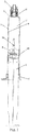
Fig.1 is a cross-sectional view of a disposable syringe according to one embodiment of the present invention, wherein the syringe is in an in-injection state. -
Fig.2 illustrates a state of the syringe ofFig.1 upon completion of the injection. -
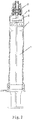
Fig.3 is an elevation view of a push rod for use in a disposable syringe according to an embodiment of the present invention. -
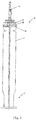
Fig.4 is an enlarged view of a distal portion of the push rod ofFig.3 . -
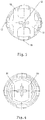
Fig.5 is a cross-sectional view taken along line A-A ofFig.4 . -
Fig.6 is a cross-sectional view taken along line B-B ofFig.4 . - A disposable syringe and a push rod for use in the disposable syringe according to the present invention will be described with reference to the specific embodiments shown in the figures. Those skilled in the art should appreciate that what is shown in the figures is only exemplary and intended to illustrate the present invention, not to limit the present invention.
- The directional terms "distal" and "proximal" used in the following detailed description are relative to medical care personnel such as a nurse for injecting for a patient, and respectively correspond to "up" and "down" of the page of
Figs.1-3 . -
Fig.1 andFig.2 respectively illustrate a disposable syringe according to one embodiment of the present invention in two states, namely, an in-injection state and a state upon completion of injection. As shown in the figures, the disposable syringe of the present invention comprises a barrel 1, a needle seat 2, apush rod 3 and arubber piston 4. The barrel 1 comprises aproximal end 5, adistal end 6 and a hollow interior 7. The hollow interior 7 is defined by a barrel-shapedinner wall 8. Therubber piston 4 is mounted on thepush rod 3 and comes in contact with theinner wall 8 to achieve liquid sealing and the discharge of a liquid medicine needed by the injection. The needle seat 2 is located at the distal end of the barrel 1 and comprises a snap-fitting mechanism (a first snap-fitting mechanism) 9. - The
push rod 3 is mounted in the interior 7 of the barrel 1 and movable in the interior of the barrel 1. Meanwhile, referring toFig.3 , thepush rod 3 comprises adistal end 10 located in the interior 7 of the barrel, aproximal end 11 located outside theproximal end 5 of the barrel, and anaxis 12 extending through theproximal end 11 and thedistal end 10 of the push rod. Thedistal end 10 of the push rod is provided with astop flange 13 and a snap-fitting mechanism (a second snap-fitting mechanism) 14 located at the distal side of thestop flange 13. The second snap-fitting mechanism 14 is adapted to engage with the first snap-fitting mechanism 9 upon completion of the injection so that when thepush rod 3 is pulled proximally, the needle seat 2 snap-fitted with thepush rod 3 can be pulled into the interior 7 of the barrel 1, thereby achieving self-destruction of the disposable syringe. The snap-fitting mechanisms 9 and 14 of the needle seat and of the push rod may be any suitable mechanism known in the art and used for self-destruction of the syringe after use. The present invention does not relate to improvements to the snap-fitting mechanism itself, so the detailed structure of the snap-fitting mechanism will not be descried herein any more. - Referring to
Fig.1 andFig.2 , more specifically, therubber piston 4 is mounted at thedistal end 10 of thepush rod 3 and located between the second snap-fitting mechanism 14 of thepush rod 3 and thestop flange 13. When thepush rod 3 moves distally, thestop flange 13 pushes and presses therubber piston 4 so that therubber piston 4 moves distally along with it to discharge the liquid medicament out of the interior 7 of the barrel 1 through a needle on the needle seat 2; after therubber piston 4 is braked upon completion of the injection, thestop flange 13 continues to push and press therubber piston 4 to produce an additional stroke needed by thepush rod 3 to engage with the needle seat 2. - Referring to
Fig.4 ,Fig.5 and Fig.6 , in thepush rod 3 for use in the disposable syringe according to the present invention, thestop flange 13 is preferably made of an elastic material. Thestop flange 13 comprises amain body portion 15 formed about theaxis 12 of thepush rod 3 and a pushing and pressingportion 16 extending from themain body portion 15 in a direction away from theaxis 12 of thepush rod 3. Therefore, the pushing and pressingportion 16 extending out of themain body portion 15 forms a cantilever structure. In the disposable syringe according to the present invention, the pushing and pressingportion 16 of the cantilever structure is used to push and press therubber piston 4. - In specific embodiment shown in the figure, the pushing and pressing
portion 16 is comprised of a plurality of finger-like portions. Those skilled in the art can readily envisage that the pushing and pressingportion 16 has a predetermined rigidity by virtue of customary designs such as selection of a material, a selection of the shape and a selection of the cross-section shape. During the injection, the sum of a frictional force and a liquid medicament resistance between therubber piston 4 and theinner wall 8 of the barrel 1 is very small. Therefore, when the pushing and pressingportion 16 pushes therubber piston 4 to move distally, the pushing and pressingportion 16 itself deforms very little or substantially does not deform. Upon completion of the injection, therubber piston 4 is stopped at the distal end 6 (namely, a zero line) of the barrel 1, and an acting force and a counterforce produced by the pushing and pressingportion 16 continuing to push and press therubber piston 4 will increase, whereupon only the pushing and pressingportion 16 deforms under the counterforce of therubber piston 4, i.e., only the pushing and pressingportion 16 deforms and therubber piston 4 does not deform. The deformation of the pushing and pressingportion 16 provides an additional stroke which is needed when afront end 11 of thepush rod 3 continues to move distally and enables the second snap-fittingmechanism 14 of thepush rod 3 to engage with the first snap-fitting mechanism 9 of the needle seat 2. As compared with therubber piston 4, the pushing and pressingportion 16 is more likely to deform. Therefore, as compared with the situation in the prior art in which a larger force is needed to deform therubber piston 4, in the present invention only a smaller force is needed to finish the additional stroke needed by thepush rod 3 for engagement of the snap-fitting mechanisms and to reduce the patient's pains. In the embodiment shown inFig.5 and Fig.6 , the plurality of finger-like portions of the pushing and pressingportion 16 are symmetrically distributed relative to a plane through theaxis 12 such asplanes axis 12, namely, arranged symmetrically about the axis. Themain body portion 15 in the figure is generally rectangular, four finger-like portions on the upper side and the lower side have the same shape, and two finger-like portions on the left side and the right side have the same shape. However, the finger-like portions on the upper and lower sides and the finger-like portions on the left and right sides are different in length and width. It can be appreciated that themain body portion 15 may be in any shape. The plurality of finger-like portions may be the same or different; they may be distributed symmetrically or asymmetrically. In the embodiment shown inFig.4 , thestop flange 13 is wholly in a shape of a sheet generally perpendicular to the axis, or at least the plurality of finger-like portions therein are in the shape of sheets generally perpendicular to the axis. - It should be appreciated that the pushing and pressing
portion 16 may be in any other shape besides the finger shape, for example, a circular shape or a polygonal shape, so long as it can meet the desired deformation. - In order to limit the deformation degree of the pushing and pressing
portion 16, or in order to prevent too much deformation of the pushing and pressingportion 16, a limitingboss 20 may be disposed at a proximal side of thestop flange 13 of thepush rod 3. In a specific example shown inFigs.3 and4 , at the distal end of thepush rod 3, a platform (e.g., a circular boss) 19 with ratchets is formed at the proximal side of thestop flange 13. The limitingboss 20 is a boss formed on theplatform 19 and having a shape corresponding to the finger-like portion 16. - In a push rod of a further preferred embodiment not shown, a portion of the
push rod 3 closely adjacent to the proximal side of thestop flange 13 is a bendable portion. In the present invention, "closely adjacent" means that there not other structures between two portions. Referring toFig.3 andFig.4 , in a specific embodiment, thebendable portion 21 is located between thestop flange 13 and thecircular boss 19. Thebendable portion 21 is formed to have a smaller diameter or thickness than other portions of thepush rod 3, or formed by any structure which is known by those skilled in the art and can produce a bent deformation. - In the case that the whole push rod is rigid, upon injection, if a push force is not coincident with the axis of the push rod, the push rod might deflect to bring the rubber piston to deflect so that a water tight function between the rubber piston and the inner wall of the barrel loses, which causes leakage. When the push rod is assembled in the interior of the barrel, if the axis of the push rod deflects relative to the axis of the barrel, it might be difficult to mount the rubber piston in the barrel. The existence of the bendable portion can solve the above problem, and thereby facilitates use and assembling of the syringe.
- Embodiments of the present invention are described in detail with reference to the drawings. Those skilled in the art should appreciate that the drawings and the corresponding depictions are only intended to illustrate the present invention. On this basis, those skilled in the art may make other variations and improvements which fall within the protection scope of the present invention.
Claims (9)
- A disposable syringe, comprising:a barrel (1), comprising a proximal end (5), a distal end (6) and a hollow interior (7), the hollow interior (7) being defined by a barrel-shaped inner wall (8);a push rod (3) located in the interior (7) of the barrel and movable in the barrel (1), the push rod (3) comprising a proximal end (11) located outside the proximal end (5) of the barrel, a distal end (10) located in the interior (7) of the barrel, and an axis (12) extending through the proximal end (11) and the distal end (10) of the push rod, the distal end (10) of the push rod being provided with a stop flange (13);a rubber piston (4) mounted on the push rod and located at a distal side of the stop flange (13) and configured to come in contact with the inner wall (8) of the barrel in a liquid tight manner,characterized in that the stop flange (13) comprises:a main body portion (15) formed about the axis (12) of the push rod, anda pushing and pressing portion (16) configured to push and press the rubber piston in a direction of said axis, the pushing and pressing portion forms a cantilever structure extending from the main body portion (15) in a direction away from the axis (12) of the push rod,wherein the pushing and pressing portion (16) is constructed in a way of being more likely to deform compared with the rubber piston (4) such that when the rubber piston (4) is stopped at the distal end of the barrel, only the pushing and pressing portion (16) deforms as continuing to push and press the rubber piston,wherein the disposable syringe further comprises a needle seat (2) located at the distal end (6) of the barrel and comprising a first snap-fitting mechanism (9); at the distal end (10) of the push rod is provided with a second snap-fitting mechanism (14) located at the distal side of the rubber piston (4), the second snap-fitting mechanism (14) is adapted to engage with the first snap-fitting mechanism (9) via deformation of the pushing and pressing portion (16) upon completion of the injection.
- The disposable syringe according to claim 1, characterized in that the stop flange (13) is made of an elastic material.
- The disposable syringe according to claim 1, characterized in that the pushing and pressing portion (16) is in a shape of a sheet generally perpendicular to the axis (12).
- The disposable syringe according to claim 1, characterized in that the pushing and pressing portion (16) is comprised of a plurality of finger-like portions which are symmetrically distributed relative to a plane (17, 18) through the axis (12).
- The disposable syringe according to claim 1, characterized in that the pushing and pressing portion (16) is comprised of a plurality of finger-like portions which are symmetrically distributed about the axis (12).
- The disposable syringe according to any one of claims 1-5, characterized in that the push rod (3) comprises a bendable portion (21) closely adjacent to the proximal side of the stop flange (13).
- The disposable syringe according to any one of claims 1-5, characterized in that the push rod (3) further comprises a limiting boss (20) located at a proximal side of the stop flange (13) to limit an amount of deformation of the pushing and pressing portion (16).
- The disposable syringe according to claim 7, characterized in that the push rod (3) further comprises a platform (19) located at the proximal side of the stop flange (13), and the limiting boss (20) is a boss formed on the platform (19) and having a shape corresponding to the finger-like portion (16).
- The disposable syringe according to claim 7, characterized in that a portion of the push rod (3) between the platform (19) and the stop flange (13) is a bendable portion (21).
Applications Claiming Priority (2)
| Application Number | Priority Date | Filing Date | Title |
|---|---|---|---|
| CN201210188526.8A CN103463713B (en) | 2012-06-06 | 2012-06-06 | Disposable syringe and push rod for disposable syringe |
| PCT/CN2012/087908 WO2013181919A1 (en) | 2012-06-06 | 2012-12-28 | Disposable syringe and push rod for the same |
Publications (3)
| Publication Number | Publication Date |
|---|---|
| EP2858700A1 EP2858700A1 (en) | 2015-04-15 |
| EP2858700A4 EP2858700A4 (en) | 2016-02-24 |
| EP2858700B1 true EP2858700B1 (en) | 2020-03-04 |
Family
ID=49711326
Family Applications (1)
| Application Number | Title | Priority Date | Filing Date |
|---|---|---|---|
| EP12878586.2A Active EP2858700B1 (en) | 2012-06-06 | 2012-12-28 | Disposable syringe and push rod for the same |
Country Status (21)
| Country | Link |
|---|---|
| US (1) | US9669166B2 (en) |
| EP (1) | EP2858700B1 (en) |
| JP (1) | JP6181165B2 (en) |
| CN (1) | CN103463713B (en) |
| AR (1) | AR091366A1 (en) |
| AU (1) | AU2012381870B2 (en) |
| BR (1) | BR112014030228B1 (en) |
| CA (1) | CA2875896A1 (en) |
| CL (1) | CL2014003313A1 (en) |
| DK (1) | DK2858700T3 (en) |
| ES (1) | ES2795805T3 (en) |
| IN (1) | IN2014DN10169A (en) |
| MA (1) | MA37607B1 (en) |
| MX (1) | MX348695B (en) |
| PT (1) | PT2858700T (en) |
| RU (1) | RU2623125C2 (en) |
| SA (1) | SA113340608B1 (en) |
| TN (1) | TN2014000494A1 (en) |
| TW (1) | TW201350159A (en) |
| WO (1) | WO2013181919A1 (en) |
| ZA (1) | ZA201408946B (en) |
Families Citing this family (5)
| Publication number | Priority date | Publication date | Assignee | Title |
|---|---|---|---|---|
| CN103830807B (en) * | 2014-01-21 | 2016-05-25 | 玉环县正日塑机有限公司 | Safe excitation apparatus in a kind of safe syringe |
| CN104759003A (en) * | 2015-04-21 | 2015-07-08 | 上海康德莱企业发展集团医疗器械有限公司 | Safety injector |
| CN113260398B (en) * | 2019-02-18 | 2023-07-04 | 泰尔茂株式会社 | Liquid medicine feeding device |
| CN110916771A (en) * | 2019-12-11 | 2020-03-27 | 房保军 | Positioning type intraspinal anesthesia needle |
| CN111658895A (en) * | 2020-06-16 | 2020-09-15 | 徐立 | Retractable safety syringe |
Family Cites Families (22)
| Publication number | Priority date | Publication date | Assignee | Title |
|---|---|---|---|---|
| US3669111A (en) | 1970-05-20 | 1972-06-13 | Ben B Dubner | Automatic retracting hypodermic syringe |
| US4346708A (en) * | 1981-04-20 | 1982-08-31 | Leveen Harry H | Syringe |
| RU2065757C1 (en) | 1991-02-20 | 1996-08-27 | Шейко Петр Андреевич | Expendable syringe |
| US5352200A (en) * | 1991-12-05 | 1994-10-04 | Roy Hammett | Non-reusable syringe with needle guard |
| CN1152882A (en) | 1994-05-06 | 1997-06-25 | 尼科梅德成像有限公司 | Low drag syringe and cartridge |
| US6053894A (en) | 1997-08-04 | 2000-04-25 | Shadd, Jr.; Daniel L. | Hypodermic syringe |
| US7798993B2 (en) * | 1998-07-29 | 2010-09-21 | Becton, Dickinson And Company | Single use syringe |
| CA2501933C (en) * | 2002-10-11 | 2013-06-18 | Becton, Dickinson And Company | Flush syringe having compressible plunger |
| TW571750U (en) * | 2002-10-16 | 2004-01-11 | Life Shield Products Inc | Retractable safety syringe with a soft piston |
| US7364569B2 (en) | 2002-11-22 | 2008-04-29 | Life Shield Products Inc | Retractable safe syringe |
| US6976975B2 (en) * | 2003-10-14 | 2005-12-20 | Syriteck Medical Devices Co., Ltd. | Safety syringe |
| US9522237B2 (en) * | 2005-01-07 | 2016-12-20 | Becton, Dickinson And Company | Positive displacement flush syringe |
| US20070073223A1 (en) * | 2005-07-06 | 2007-03-29 | Hung-Chi Huang | Push rod of a syringe |
| TWI270386B (en) * | 2005-10-31 | 2007-01-11 | Fen-Fang Jang | Syringe |
| JP4965582B2 (en) * | 2006-11-22 | 2012-07-04 | マリンクロッド エルエルシー | Universal adapter for syringe plunger |
| CN1961982A (en) * | 2006-12-12 | 2007-05-16 | 李英日 | Disposable syringe |
| DE202007005394U1 (en) | 2007-04-13 | 2007-08-09 | B. Braun Melsungen Ag | Safety nozzle, has piston rod whose release movement is enabled in distal direction relative to nozzle cylinder during attachment of piston to distal front wall of piston rod, in order to release retaining flange |
| EP2554204B1 (en) | 2010-03-29 | 2017-11-08 | Terumo Kabushiki Kaisha | Prefilled syringe |
| CN101862490B (en) * | 2010-06-21 | 2012-07-11 | 温岭市千禧光医疗器械有限公司 | Self-destruction insulin syringe capable of replacing needle |
| EP2593162B1 (en) * | 2010-07-13 | 2015-06-03 | Novo Nordisk A/S | A piston rod foot |
| WO2013153121A2 (en) | 2012-04-10 | 2013-10-17 | Novo Nordisk A/S | Medical injection device with time delay indicator |
| CN202569095U (en) * | 2012-06-06 | 2012-12-05 | 上海萌黎国际贸易有限公司 | Disposable syringe and push rod for same |
-
2012
- 2012-06-06 CN CN201210188526.8A patent/CN103463713B/en active Active
- 2012-12-28 US US14/405,627 patent/US9669166B2/en active Active
- 2012-12-28 BR BR112014030228-6A patent/BR112014030228B1/en active IP Right Grant
- 2012-12-28 WO PCT/CN2012/087908 patent/WO2013181919A1/en active Application Filing
- 2012-12-28 MX MX2014014787A patent/MX348695B/en active IP Right Grant
- 2012-12-28 JP JP2015515369A patent/JP6181165B2/en active Active
- 2012-12-28 PT PT128785862T patent/PT2858700T/en unknown
- 2012-12-28 CA CA2875896A patent/CA2875896A1/en not_active Abandoned
- 2012-12-28 RU RU2014152481A patent/RU2623125C2/en not_active IP Right Cessation
- 2012-12-28 MA MA37607A patent/MA37607B1/en unknown
- 2012-12-28 ES ES12878586T patent/ES2795805T3/en active Active
- 2012-12-28 AU AU2012381870A patent/AU2012381870B2/en not_active Ceased
- 2012-12-28 EP EP12878586.2A patent/EP2858700B1/en active Active
- 2012-12-28 DK DK12878586.2T patent/DK2858700T3/en active
-
2013
- 2013-06-01 SA SA113340608A patent/SA113340608B1/en unknown
- 2013-06-03 AR ARP130101949 patent/AR091366A1/en unknown
- 2013-06-04 TW TW102119797A patent/TW201350159A/en unknown
-
2014
- 2014-11-27 TN TN2014000494A patent/TN2014000494A1/en unknown
- 2014-11-28 IN IN10169DEN2014 patent/IN2014DN10169A/en unknown
- 2014-12-04 CL CL2014003313A patent/CL2014003313A1/en unknown
- 2014-12-05 ZA ZA2014/08946A patent/ZA201408946B/en unknown
Non-Patent Citations (1)
| Title |
|---|
| None * |
Also Published As
| Publication number | Publication date |
|---|---|
| CA2875896A1 (en) | 2013-12-12 |
| ZA201408946B (en) | 2015-10-28 |
| PT2858700T (en) | 2020-06-17 |
| WO2013181919A1 (en) | 2013-12-12 |
| CN103463713A (en) | 2013-12-25 |
| RU2623125C2 (en) | 2017-06-22 |
| BR112014030228A2 (en) | 2017-06-27 |
| MA37607A1 (en) | 2016-10-31 |
| IN2014DN10169A (en) | 2015-08-21 |
| RU2014152481A (en) | 2016-08-10 |
| AU2012381870A1 (en) | 2015-01-15 |
| US20150148743A1 (en) | 2015-05-28 |
| DK2858700T3 (en) | 2020-06-08 |
| EP2858700A4 (en) | 2016-02-24 |
| EP2858700A1 (en) | 2015-04-15 |
| SA113340608B1 (en) | 2016-02-16 |
| MX348695B (en) | 2017-06-26 |
| MA37607B1 (en) | 2017-05-31 |
| TN2014000494A1 (en) | 2016-03-30 |
| JP6181165B2 (en) | 2017-08-16 |
| AR091366A1 (en) | 2015-01-28 |
| US9669166B2 (en) | 2017-06-06 |
| MX2014014787A (en) | 2015-04-10 |
| JP2015518758A (en) | 2015-07-06 |
| ES2795805T3 (en) | 2020-11-24 |
| CN103463713B (en) | 2019-09-13 |
| AU2012381870B2 (en) | 2018-07-05 |
| TW201350159A (en) | 2013-12-16 |
| CL2014003313A1 (en) | 2015-06-12 |
| BR112014030228B1 (en) | 2021-06-01 |
Similar Documents
| Publication | Publication Date | Title |
|---|---|---|
| JP6526141B2 (en) | Dual chamber passive pull-in needle syringe | |
| EP2858700B1 (en) | Disposable syringe and push rod for the same | |
| JP3097951B2 (en) | Continuous motion stopper | |
| EP1758627B1 (en) | Improvements relating to automatic injection devices | |
| TWI597084B (en) | Auto-injector | |
| EP2903663B1 (en) | Injector apparatus | |
| JP5993919B2 (en) | Safety syringe | |
| EP2663352B1 (en) | Auto-disable safety syringe | |
| JP5409614B2 (en) | Syringe assembly including anti-reuse mechanism | |
| EP2885027B1 (en) | A spring-loaded injection device with an injection button | |
| WO2011026932A1 (en) | Cupped piston for a cartridge for drug delivery devices | |
| CN112041008B (en) | Auto-disabling pre-filled syringe with plunger rod spring |
Legal Events
| Date | Code | Title | Description |
|---|---|---|---|
| PUAI | Public reference made under article 153(3) epc to a published international application that has entered the european phase |
Free format text: ORIGINAL CODE: 0009012 |
|
| 17P | Request for examination filed |
Effective date: 20150106 |
|
| AK | Designated contracting states |
Kind code of ref document: A1 Designated state(s): AL AT BE BG CH CY CZ DE DK EE ES FI FR GB GR HR HU IE IS IT LI LT LU LV MC MK MT NL NO PL PT RO RS SE SI SK SM TR |
|
| AX | Request for extension of the european patent |
Extension state: BA ME |
|
| RA4 | Supplementary search report drawn up and despatched (corrected) |
Effective date: 20160125 |
|
| RIC1 | Information provided on ipc code assigned before grant |
Ipc: A61M 5/315 20060101AFI20160119BHEP Ipc: A61M 5/50 20060101ALI20160119BHEP |
|
| RAP1 | Party data changed (applicant data changed or rights of an application transferred) |
Owner name: SOL-MILLENNIUM MEDICAL HK LIMITED |
|
| STAA | Information on the status of an ep patent application or granted ep patent |
Free format text: STATUS: EXAMINATION IS IN PROGRESS |
|
| 17Q | First examination report despatched |
Effective date: 20190607 |
|
| GRAP | Despatch of communication of intention to grant a patent |
Free format text: ORIGINAL CODE: EPIDOSNIGR1 |
|
| STAA | Information on the status of an ep patent application or granted ep patent |
Free format text: STATUS: GRANT OF PATENT IS INTENDED |
|
| INTG | Intention to grant announced |
Effective date: 20191107 |
|
| GRAS | Grant fee paid |
Free format text: ORIGINAL CODE: EPIDOSNIGR3 |
|
| GRAA | (expected) grant |
Free format text: ORIGINAL CODE: 0009210 |
|
| STAA | Information on the status of an ep patent application or granted ep patent |
Free format text: STATUS: THE PATENT HAS BEEN GRANTED |
|
| AK | Designated contracting states |
Kind code of ref document: B1 Designated state(s): AL AT BE BG CH CY CZ DE DK EE ES FI FR GB GR HR HU IE IS IT LI LT LU LV MC MK MT NL NO PL PT RO RS SE SI SK SM TR |
|
| AX | Request for extension of the european patent |
Extension state: BA ME |
|
| REG | Reference to a national code |
Ref country code: GB Ref legal event code: FG4D |
|
| REG | Reference to a national code |
Ref country code: CH Ref legal event code: EP |
|
| REG | Reference to a national code |
Ref country code: AT Ref legal event code: REF Ref document number: 1239663 Country of ref document: AT Kind code of ref document: T Effective date: 20200315 |
|
| REG | Reference to a national code |
Ref country code: DE Ref legal event code: R096 Ref document number: 602012068303 Country of ref document: DE |
|
| REG | Reference to a national code |
Ref country code: IE Ref legal event code: FG4D |
|
| REG | Reference to a national code |
Ref country code: DK Ref legal event code: T3 Effective date: 20200605 Ref country code: FI Ref legal event code: FGE |
|
| REG | Reference to a national code |
Ref country code: PT Ref legal event code: SC4A Ref document number: 2858700 Country of ref document: PT Date of ref document: 20200617 Kind code of ref document: T Free format text: AVAILABILITY OF NATIONAL TRANSLATION Effective date: 20200603 Ref country code: NL Ref legal event code: FP |
|
| REG | Reference to a national code |
Ref country code: SE Ref legal event code: TRGR |
|
| PG25 | Lapsed in a contracting state [announced via postgrant information from national office to epo] |
Ref country code: RS Free format text: LAPSE BECAUSE OF FAILURE TO SUBMIT A TRANSLATION OF THE DESCRIPTION OR TO PAY THE FEE WITHIN THE PRESCRIBED TIME-LIMIT Effective date: 20200304 Ref country code: NO Free format text: LAPSE BECAUSE OF FAILURE TO SUBMIT A TRANSLATION OF THE DESCRIPTION OR TO PAY THE FEE WITHIN THE PRESCRIBED TIME-LIMIT Effective date: 20200604 |
|
| PG25 | Lapsed in a contracting state [announced via postgrant information from national office to epo] |
Ref country code: GR Free format text: LAPSE BECAUSE OF FAILURE TO SUBMIT A TRANSLATION OF THE DESCRIPTION OR TO PAY THE FEE WITHIN THE PRESCRIBED TIME-LIMIT Effective date: 20200605 Ref country code: BG Free format text: LAPSE BECAUSE OF FAILURE TO SUBMIT A TRANSLATION OF THE DESCRIPTION OR TO PAY THE FEE WITHIN THE PRESCRIBED TIME-LIMIT Effective date: 20200604 Ref country code: HR Free format text: LAPSE BECAUSE OF FAILURE TO SUBMIT A TRANSLATION OF THE DESCRIPTION OR TO PAY THE FEE WITHIN THE PRESCRIBED TIME-LIMIT Effective date: 20200304 Ref country code: LV Free format text: LAPSE BECAUSE OF FAILURE TO SUBMIT A TRANSLATION OF THE DESCRIPTION OR TO PAY THE FEE WITHIN THE PRESCRIBED TIME-LIMIT Effective date: 20200304 |
|
| REG | Reference to a national code |
Ref country code: LT Ref legal event code: MG4D |
|
| PG25 | Lapsed in a contracting state [announced via postgrant information from national office to epo] |
Ref country code: IS Free format text: LAPSE BECAUSE OF FAILURE TO SUBMIT A TRANSLATION OF THE DESCRIPTION OR TO PAY THE FEE WITHIN THE PRESCRIBED TIME-LIMIT Effective date: 20200704 Ref country code: SK Free format text: LAPSE BECAUSE OF FAILURE TO SUBMIT A TRANSLATION OF THE DESCRIPTION OR TO PAY THE FEE WITHIN THE PRESCRIBED TIME-LIMIT Effective date: 20200304 Ref country code: RO Free format text: LAPSE BECAUSE OF FAILURE TO SUBMIT A TRANSLATION OF THE DESCRIPTION OR TO PAY THE FEE WITHIN THE PRESCRIBED TIME-LIMIT Effective date: 20200304 Ref country code: EE Free format text: LAPSE BECAUSE OF FAILURE TO SUBMIT A TRANSLATION OF THE DESCRIPTION OR TO PAY THE FEE WITHIN THE PRESCRIBED TIME-LIMIT Effective date: 20200304 Ref country code: CZ Free format text: LAPSE BECAUSE OF FAILURE TO SUBMIT A TRANSLATION OF THE DESCRIPTION OR TO PAY THE FEE WITHIN THE PRESCRIBED TIME-LIMIT Effective date: 20200304 Ref country code: LT Free format text: LAPSE BECAUSE OF FAILURE TO SUBMIT A TRANSLATION OF THE DESCRIPTION OR TO PAY THE FEE WITHIN THE PRESCRIBED TIME-LIMIT Effective date: 20200304 Ref country code: SM Free format text: LAPSE BECAUSE OF FAILURE TO SUBMIT A TRANSLATION OF THE DESCRIPTION OR TO PAY THE FEE WITHIN THE PRESCRIBED TIME-LIMIT Effective date: 20200304 |
|
| REG | Reference to a national code |
Ref country code: ES Ref legal event code: FG2A Ref document number: 2795805 Country of ref document: ES Kind code of ref document: T3 Effective date: 20201124 |
|
| REG | Reference to a national code |
Ref country code: DE Ref legal event code: R097 Ref document number: 602012068303 Country of ref document: DE |
|
| PLBE | No opposition filed within time limit |
Free format text: ORIGINAL CODE: 0009261 |
|
| STAA | Information on the status of an ep patent application or granted ep patent |
Free format text: STATUS: NO OPPOSITION FILED WITHIN TIME LIMIT |
|
| 26N | No opposition filed |
Effective date: 20201207 |
|
| PG25 | Lapsed in a contracting state [announced via postgrant information from national office to epo] |
Ref country code: SI Free format text: LAPSE BECAUSE OF FAILURE TO SUBMIT A TRANSLATION OF THE DESCRIPTION OR TO PAY THE FEE WITHIN THE PRESCRIBED TIME-LIMIT Effective date: 20200304 Ref country code: PL Free format text: LAPSE BECAUSE OF FAILURE TO SUBMIT A TRANSLATION OF THE DESCRIPTION OR TO PAY THE FEE WITHIN THE PRESCRIBED TIME-LIMIT Effective date: 20200304 |
|
| REG | Reference to a national code |
Ref country code: FI Ref legal event code: MAE |
|
| REG | Reference to a national code |
Ref country code: DK Ref legal event code: EBP Effective date: 20201231 |
|
| PG25 | Lapsed in a contracting state [announced via postgrant information from national office to epo] |
Ref country code: FI Free format text: LAPSE BECAUSE OF NON-PAYMENT OF DUE FEES Effective date: 20201228 |
|
| REG | Reference to a national code |
Ref country code: CH Ref legal event code: PL |
|
| PG25 | Lapsed in a contracting state [announced via postgrant information from national office to epo] |
Ref country code: MC Free format text: LAPSE BECAUSE OF FAILURE TO SUBMIT A TRANSLATION OF THE DESCRIPTION OR TO PAY THE FEE WITHIN THE PRESCRIBED TIME-LIMIT Effective date: 20200304 |
|
| PG25 | Lapsed in a contracting state [announced via postgrant information from national office to epo] |
Ref country code: LU Free format text: LAPSE BECAUSE OF NON-PAYMENT OF DUE FEES Effective date: 20201228 Ref country code: IE Free format text: LAPSE BECAUSE OF NON-PAYMENT OF DUE FEES Effective date: 20201228 |
|
| PG25 | Lapsed in a contracting state [announced via postgrant information from national office to epo] |
Ref country code: CH Free format text: LAPSE BECAUSE OF NON-PAYMENT OF DUE FEES Effective date: 20201231 Ref country code: LI Free format text: LAPSE BECAUSE OF NON-PAYMENT OF DUE FEES Effective date: 20201231 |
|
| PG25 | Lapsed in a contracting state [announced via postgrant information from national office to epo] |
Ref country code: DK Free format text: LAPSE BECAUSE OF NON-PAYMENT OF DUE FEES Effective date: 20201231 |
|
| REG | Reference to a national code |
Ref country code: AT Ref legal event code: UEP Ref document number: 1239663 Country of ref document: AT Kind code of ref document: T Effective date: 20200304 |
|
| PG25 | Lapsed in a contracting state [announced via postgrant information from national office to epo] |
Ref country code: MT Free format text: LAPSE BECAUSE OF FAILURE TO SUBMIT A TRANSLATION OF THE DESCRIPTION OR TO PAY THE FEE WITHIN THE PRESCRIBED TIME-LIMIT Effective date: 20200304 Ref country code: CY Free format text: LAPSE BECAUSE OF FAILURE TO SUBMIT A TRANSLATION OF THE DESCRIPTION OR TO PAY THE FEE WITHIN THE PRESCRIBED TIME-LIMIT Effective date: 20200304 |
|
| PG25 | Lapsed in a contracting state [announced via postgrant information from national office to epo] |
Ref country code: MK Free format text: LAPSE BECAUSE OF FAILURE TO SUBMIT A TRANSLATION OF THE DESCRIPTION OR TO PAY THE FEE WITHIN THE PRESCRIBED TIME-LIMIT Effective date: 20200304 Ref country code: AL Free format text: LAPSE BECAUSE OF FAILURE TO SUBMIT A TRANSLATION OF THE DESCRIPTION OR TO PAY THE FEE WITHIN THE PRESCRIBED TIME-LIMIT Effective date: 20200304 |
|
| PGFP | Annual fee paid to national office [announced via postgrant information from national office to epo] |
Ref country code: IT Payment date: 20221129 Year of fee payment: 11 Ref country code: AT Payment date: 20221125 Year of fee payment: 11 |
|
| PGFP | Annual fee paid to national office [announced via postgrant information from national office to epo] |
Ref country code: BE Payment date: 20221118 Year of fee payment: 11 |
|
| PGFP | Annual fee paid to national office [announced via postgrant information from national office to epo] |
Ref country code: TR Payment date: 20221223 Year of fee payment: 11 Ref country code: ES Payment date: 20230109 Year of fee payment: 11 |
|
| P01 | Opt-out of the competence of the unified patent court (upc) registered |
Effective date: 20230608 |
|
| PGFP | Annual fee paid to national office [announced via postgrant information from national office to epo] |
Ref country code: GB Payment date: 20231221 Year of fee payment: 12 |
|
| PGFP | Annual fee paid to national office [announced via postgrant information from national office to epo] |
Ref country code: SE Payment date: 20231219 Year of fee payment: 12 Ref country code: PT Payment date: 20231220 Year of fee payment: 12 Ref country code: DE Payment date: 20231219 Year of fee payment: 12 Ref country code: NL Payment date: 20231218 Year of fee payment: 12 Ref country code: FR Payment date: 20231221 Year of fee payment: 12 |
|
| PGFP | Annual fee paid to national office [announced via postgrant information from national office to epo] |
Ref country code: ES Payment date: 20240118 Year of fee payment: 12 |