EP2858000A1 - Anzeigevorrichtung und Anzeigeverfahren damit - Google Patents
Anzeigevorrichtung und Anzeigeverfahren damit Download PDFInfo
- Publication number
- EP2858000A1 EP2858000A1 EP14187055.0A EP14187055A EP2858000A1 EP 2858000 A1 EP2858000 A1 EP 2858000A1 EP 14187055 A EP14187055 A EP 14187055A EP 2858000 A1 EP2858000 A1 EP 2858000A1
- Authority
- EP
- European Patent Office
- Prior art keywords
- region
- image
- screen
- displayed
- boundary
- Prior art date
- Legal status (The legal status is an assumption and is not a legal conclusion. Google has not performed a legal analysis and makes no representation as to the accuracy of the status listed.)
- Ceased
Links
Images


Classifications
-
- G—PHYSICS
- G16—INFORMATION AND COMMUNICATION TECHNOLOGY [ICT] SPECIALLY ADAPTED FOR SPECIFIC APPLICATION FIELDS
- G16H—HEALTHCARE INFORMATICS, i.e. INFORMATION AND COMMUNICATION TECHNOLOGY [ICT] SPECIALLY ADAPTED FOR THE HANDLING OR PROCESSING OF MEDICAL OR HEALTHCARE DATA
- G16H40/00—ICT specially adapted for the management or administration of healthcare resources or facilities; ICT specially adapted for the management or operation of medical equipment or devices
- G16H40/60—ICT specially adapted for the management or administration of healthcare resources or facilities; ICT specially adapted for the management or operation of medical equipment or devices for the operation of medical equipment or devices
- G16H40/63—ICT specially adapted for the management or administration of healthcare resources or facilities; ICT specially adapted for the management or operation of medical equipment or devices for the operation of medical equipment or devices for local operation
-
- G—PHYSICS
- G06—COMPUTING; CALCULATING OR COUNTING
- G06F—ELECTRIC DIGITAL DATA PROCESSING
- G06F3/00—Input arrangements for transferring data to be processed into a form capable of being handled by the computer; Output arrangements for transferring data from processing unit to output unit, e.g. interface arrangements
- G06F3/01—Input arrangements or combined input and output arrangements for interaction between user and computer
- G06F3/048—Interaction techniques based on graphical user interfaces [GUI]
-
- A—HUMAN NECESSITIES
- A61—MEDICAL OR VETERINARY SCIENCE; HYGIENE
- A61B—DIAGNOSIS; SURGERY; IDENTIFICATION
- A61B5/00—Measuring for diagnostic purposes; Identification of persons
-
- G—PHYSICS
- G06—COMPUTING; CALCULATING OR COUNTING
- G06F—ELECTRIC DIGITAL DATA PROCESSING
- G06F3/00—Input arrangements for transferring data to be processed into a form capable of being handled by the computer; Output arrangements for transferring data from processing unit to output unit, e.g. interface arrangements
- G06F3/01—Input arrangements or combined input and output arrangements for interaction between user and computer
- G06F3/048—Interaction techniques based on graphical user interfaces [GUI]
- G06F3/0487—Interaction techniques based on graphical user interfaces [GUI] using specific features provided by the input device, e.g. functions controlled by the rotation of a mouse with dual sensing arrangements, or of the nature of the input device, e.g. tap gestures based on pressure sensed by a digitiser
- G06F3/0488—Interaction techniques based on graphical user interfaces [GUI] using specific features provided by the input device, e.g. functions controlled by the rotation of a mouse with dual sensing arrangements, or of the nature of the input device, e.g. tap gestures based on pressure sensed by a digitiser using a touch-screen or digitiser, e.g. input of commands through traced gestures
-
- G—PHYSICS
- G06—COMPUTING; CALCULATING OR COUNTING
- G06F—ELECTRIC DIGITAL DATA PROCESSING
- G06F3/00—Input arrangements for transferring data to be processed into a form capable of being handled by the computer; Output arrangements for transferring data from processing unit to output unit, e.g. interface arrangements
- G06F3/14—Digital output to display device ; Cooperation and interconnection of the display device with other functional units
-
- G—PHYSICS
- G06—COMPUTING; CALCULATING OR COUNTING
- G06T—IMAGE DATA PROCESSING OR GENERATION, IN GENERAL
- G06T3/00—Geometric image transformation in the plane of the image
- G06T3/40—Scaling the whole image or part thereof
-
- G—PHYSICS
- G06—COMPUTING; CALCULATING OR COUNTING
- G06T—IMAGE DATA PROCESSING OR GENERATION, IN GENERAL
- G06T7/00—Image analysis
- G06T7/0002—Inspection of images, e.g. flaw detection
- G06T7/0012—Biomedical image inspection
-
- G—PHYSICS
- G09—EDUCATION; CRYPTOGRAPHY; DISPLAY; ADVERTISING; SEALS
- G09G—ARRANGEMENTS OR CIRCUITS FOR CONTROL OF INDICATING DEVICES USING STATIC MEANS TO PRESENT VARIABLE INFORMATION
- G09G5/00—Control arrangements or circuits for visual indicators common to cathode-ray tube indicators and other visual indicators
- G09G5/14—Display of multiple viewports
-
- G—PHYSICS
- G16—INFORMATION AND COMMUNICATION TECHNOLOGY [ICT] SPECIALLY ADAPTED FOR SPECIFIC APPLICATION FIELDS
- G16H—HEALTHCARE INFORMATICS, i.e. INFORMATION AND COMMUNICATION TECHNOLOGY [ICT] SPECIALLY ADAPTED FOR THE HANDLING OR PROCESSING OF MEDICAL OR HEALTHCARE DATA
- G16H30/00—ICT specially adapted for the handling or processing of medical images
- G16H30/20—ICT specially adapted for the handling or processing of medical images for handling medical images, e.g. DICOM, HL7 or PACS
-
- G—PHYSICS
- G16—INFORMATION AND COMMUNICATION TECHNOLOGY [ICT] SPECIALLY ADAPTED FOR SPECIFIC APPLICATION FIELDS
- G16H—HEALTHCARE INFORMATICS, i.e. INFORMATION AND COMMUNICATION TECHNOLOGY [ICT] SPECIALLY ADAPTED FOR THE HANDLING OR PROCESSING OF MEDICAL OR HEALTHCARE DATA
- G16H50/00—ICT specially adapted for medical diagnosis, medical simulation or medical data mining; ICT specially adapted for detecting, monitoring or modelling epidemics or pandemics
- G16H50/20—ICT specially adapted for medical diagnosis, medical simulation or medical data mining; ICT specially adapted for detecting, monitoring or modelling epidemics or pandemics for computer-aided diagnosis, e.g. based on medical expert systems
-
- G—PHYSICS
- G06—COMPUTING; CALCULATING OR COUNTING
- G06T—IMAGE DATA PROCESSING OR GENERATION, IN GENERAL
- G06T2200/00—Indexing scheme for image data processing or generation, in general
- G06T2200/24—Indexing scheme for image data processing or generation, in general involving graphical user interfaces [GUIs]
-
- G—PHYSICS
- G06—COMPUTING; CALCULATING OR COUNTING
- G06T—IMAGE DATA PROCESSING OR GENERATION, IN GENERAL
- G06T2207/00—Indexing scheme for image analysis or image enhancement
- G06T2207/10—Image acquisition modality
- G06T2207/10072—Tomographic images
-
- G—PHYSICS
- G06—COMPUTING; CALCULATING OR COUNTING
- G06T—IMAGE DATA PROCESSING OR GENERATION, IN GENERAL
- G06T2207/00—Indexing scheme for image analysis or image enhancement
- G06T2207/10—Image acquisition modality
- G06T2207/10116—X-ray image
-
- G—PHYSICS
- G09—EDUCATION; CRYPTOGRAPHY; DISPLAY; ADVERTISING; SEALS
- G09G—ARRANGEMENTS OR CIRCUITS FOR CONTROL OF INDICATING DEVICES USING STATIC MEANS TO PRESENT VARIABLE INFORMATION
- G09G2340/00—Aspects of display data processing
- G09G2340/12—Overlay of images, i.e. displayed pixel being the result of switching between the corresponding input pixels
Definitions
- Exemplary embodiments relate to a display apparatus which is usable for displaying images.
- a display apparatus includes a memory configured to store a plurality of different respective types of images of an object, an input device configured to receive an input of a command which relates to simultaneously displaying the different types of images, and a display device configured to display images, wherein, upon receiving the input of the command, the display device is further configured to divide a screen upon which an image of the object is displayable into a first region within which a first image showing one portion of the object is displayed and a second region within which a second image showing a remaining portion of the object is displayed.
- a display apparatus includes a memory configured to store a plurality of different respective types of images of an object, an input device configured to receive an input of one of a division command and a shift command, and a display device configured to display images, wherein the display device is further configured to divide, when the division command is received, a screen upon which an image of the object is displayable into a first region within which a first image showing one portion of the object is displayed and a second region within which a second image showing a remaining portion of the object is displayed, and wherein the display device is further configured to shift, when the shift command is received, a boundary between the first region and the second region based on the shift command, and to change at least one from among relative screen shares of the first region and the second region and a respective proportional amount of the corresponding portion of the object shown in each of the first image and the second image based on the shift command.
- an image display method for displaying a plurality of images showing a specific region of an object includes seamlessly displaying one portion of each of the images on a display device such that the displayed portions of the images showing the specific region of the object are combined to form a combination image of the specific region of the object.
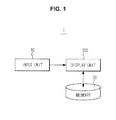
- FIG. 1 is a view which illustrates an exemplary configuration of a display apparatus.
- the display apparatus 1 includes a display unit (also referred to herein as a "display device” and/or as a “display”) 100 configured to display an image, a memory 20 configured to store images of an object which is displayed on the display unit 100, and an input unit (also referred to herein as an "input device") 10 configured to receive an input of a command which relates to a manipulation of the display apparatus 1.
- the display apparatus 1 according to an exemplary embodiment, which refers to a concept which covers any or all of various types of devices which are capable of displaying images, may include any one or more of a desktop computer, a laptop computer, a tablet computer, and a smartphone.
- the display unit 100 which is a constituent of the display apparatus 1 and which includes a screen configured to display an image, may be implemented with any one or more of various kinds of commonly known display techniques.
- the display unit 100 may be implemented using a touchscreen configured to enable a user to input a command by directly touching the display unit 100, as well as via the input unit 10.
- the user is able to input a desired command to the display apparatus 1 by touching the display unit 100 with a finger or a touch pen (e.g., a stylus).
- the input unit 10 may include any one or more of a keyboard, a mouse, a joystick, a track ball, a jog wheel, a voice recognition device, and a motion recognition device.
- the input unit 10 may be integrated with the display apparatus 1 or installed in the display apparatus 1. Alternatively, the input unit may be provided separately from the display apparatus. In the case that the input unit is provided separately from the display apparatus, the input unit 10 may transmit a received command to the display apparatus via wireless communication, or may be connected to the display apparatus via any one or more of various kinds of connectors.
- the user sometimes needs to check images of the same object, and/or to check a specific region of the same object for which a corresponding image has been captured by using different techniques. In particular, this process is often necessary in the field of medicine.
- any one or more of various modalities such as an x-ray apparatus, an ultrasound apparatus, a computed tomography apparatus, a magnetic resonance imaging apparatus, a positron emission tomography apparatus, and a single photon emission computed tomography apparatus, may be used to diagnose a disease.
- Each modality uses one or more of various kinds of imaging techniques to photograph an object.
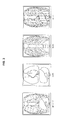
- the x-ray apparatus may obtain any one or more of a general x-ray image which shows all bones and soft tissues such as organs of the object, a bone x-ray image which shows only bones, a soft tissue x-ray image which shows only soft tissues such as organs, and a color x-ray image which provides a sharp contrast of colors.
- the medical staff compares medical images of an object which are captured via various techniques of modalities as described above in order to check a region which is suspected of having a lesion.
- multiple display apparatuses are generally used.
- using a single display apparatus to simultaneously compare various types of medical images may ensure a more intuitive and efficient comparison.
- disclosed exemplary embodiments provide a user interface which facilitates a simultaneous checking and comparison of a plurality of medical images which have been captured by using different techniques on a single display apparatus and a display apparatus which includes such a user interface.
- exemplary embodiments will be described in a context which relates to x-ray images used for medical diagnosis.
- the technical spirit of the exemplary embodiments is not limited to medical images, and is rather applicable to any and all fields for which a comparison and analysis of a plurality of images is useful.
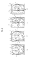
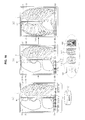
- FIG. 2 illustrates an exemplary process for dividing the screen of a display unit
- FIG. 3 shows a general x-ray image (general), a soft tissue x-ray image (soft), bone x-ray image (bone), and a color x-ray image (color) as examples of x-ray images.
- a captured general x-ray image of the chest region of an object is displayed on the display unit 100, and markers 110 and 111 which are usable for effecting a division of the screen are respectively displayed on the left and right sides of the display unit 100.
- the x-ray image is an example of a medical image.
- Medical images that may be displayed on the display unit 100 are not limited to x-ray images, but include images which may be captured via other kinds of modalities, such as an ultrasound apparatus, a computed tomography apparatus, a magnetic resonance imaging apparatus, a positron emission tomography apparatus, and a single photon emission computed tomography apparatus.
- Drawing (a) of FIG. 2 shows a display region of the display unit 100 prior to an implementation of a screen division.
- a first region 120 in which a first image 121 which correspond to a general x-ray image is displayed, accounts for the entire display region of the display unit 100.
- the first image 121 which is displayed in the first region 120 prior to an implementation of a screen division, may be utilized as a reference image to be compared with other images which have been captured by using different techniques. Accordingly, the general x-ray image shown in FIG. 3 may be displayed as the first image 121.
- exemplary embodiments are not limited thereto.
- Various types of images which may be acquired by capturing images of a specific region of the same body by using different techniques, such as the bone x-ray image, the soft tissue x-ray image, and/or the color x-ray image of the same object shown in FIG. 3 , may be selected and displayed by a user.
- the screen is divided into the first region 120 and a second region 130.
- a vertical boundary line vb1 which passes through the marker 110 is created.
- the vertical boundary line vb1 moves together with the marker 110 in the direction in which the marker 110 is dragged.
- the vertical boundary line vb1 serves as a boundary between the first region 120 and the second region 130.
- the direction in which the marker 110 is movable may be indicated by a symbol, such as, for example, an arrow.
- clicking and dragging of the marker 110 may be performed via the aforementioned input unit 10, which may include any one or more devices, such as a mouse, a keyboard, a track ball, a joystick, jog wheel, a voice recognition device, and a motion recognition device.
- the second image 131 is an x-ray image of the same region or section of the same object.
- the second image 131 is a soft tissue x-ray image which shows soft tissue of the object but does not show bones (see. e.g., the drawing labeled "soft" in FIG. 3 ).
- the soft tissue x-ray image is simply an example, and the second image 131 may include any one or more of various images which may be acquired by photographing the same section of the object as that represented by the first image 121 by using other imaging techniques.
- the screen shares of the first region 120 and the second region 130 vary based on a corresponding movement of the marker 110, and thereby the proportional amounts of the object regions shown in the first image 121 and the second image 131 vary.
- the first image 121 and the second image 131 naturally match with each other at the vertical boundary line vb1.
- the images matching with each other as above represent the entire image of the photographed region of the object, similarly as in the case of the image prior to screen division.
- the user may move the marker 110 near the region of interest, and thus may easily and quickly check the first image 121 and the second image 131 for the region of interest in an alternating manner.
- the user may seamlessly compare different types of images of the region of interest which have been captured by using different techniques, thus displaying unique information on a single display apparatus, rather than on a plurality of separate display apparatuses. Because it is possible to seamlessly check multiple images of the same region on one display apparatus 1 at the same time, an accuracy of diagnosis may be enhanced, and a more intuitive diagnosis may be possible.
- FIG. 4 illustrates an exemplary process for dividing the screen of the display unit by directly touching the display unit.
- the exemplary embodiment illustrated in FIG. 4 differs from the exemplary embodiment of FIG. 2 in that the marker 110 of the display unit 100 is touched using a touch tool, such as, for example, a finger or a touch pen.
- the display unit 100 may use any one or more of various kinds of commonly known touchscreens in order to facilitate input of a command by touch. Other technical details except this difference are the same as those of the exemplary embodiment of FIG. 2 , and thus a description thereof will be omitted.
- FIG. 5 illustrates another exemplary process for dividing the screen of the display unit.
- the exemplary embodiment illustrated in FIG. 5 differs from the embodiment of FIG. 2 in that the right marker 111 is clicked and moved and a bone x-ray image (see the drawing labeled "bone" in FIG. 3 ) is used as a second image 141 to be displayed on a second region 140.
- Other technical details except this difference are the same as those of the exemplary embodiment of FIG. 2 , and thus a description thereof will be omitted.
- the user may divide the screen by dragging the marker 110 displayed on the left side of the display unit 100, as shown in FIG. 2 .
- the user may divide the screen by dragging the marker 111 displayed on the right side of the display unit 100, as shown in FIG. 5 .
- the images displayed in the second regions 130 and 140 of the divided screen may be replaced with a different type of images.
- the image displayed in the first region 120 may also be replaced with a different type of image. This will be described below with reference to FIGS. 16 , 17 , 18 , and 19 .
- FIG. 6 illustrates another exemplary process for dividing the screen by directly touching the display unit.
- the exemplary embodiment illustrated in FIG. 6 differs from the exemplary embodiment of FIG. 5 in that the marker 111 of the display unit 100 is touched by using a touch tool, such as a finger or a touch pen.
- the display unit 100 may use any one or more of various kinds of commonly known touchscreens in order to facilitate input of a command by touch. Other technical details except this difference are the same as those of the exemplary embodiment of FIG. 5 , and thus a description thereof will be omitted.
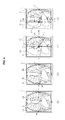
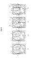
- FIG. 7 illustrates another exemplary process for dividing the screen of the display unit into three regions.
- FIG. 7 Drawings (a), (b), (c), and (d) of FIG. 7 are respectively identical to drawings (a), (b), (c), and (d) of FIG. 2 , and thus a description thereof will be omitted.
- the screen is divided into a first region 120, which is at the center, and a second region 130 and a third region 160, which are separately arranged on the left and right sides, respectively.
- a vertical boundary line vb2 which passes through the marker 111 is created.
- the vertical boundary line vb2 moves together with the marker 111 in the dragging direction of the marker 111.
- the proportional amount of the object on the first image 121 displayed in the first region 120 also correspondingly decreases.
- the first image 121 shows approximately 2/3 of the object.
- the first image 121 shows only approximately 1/3 of the object, and the remaining approximately 1/3 of the object is shown in a third image 161 which is displayed in the newly produced third region 160.
- the combination of the first region 120 displaying the first image 121, the second region 130 displaying the second image 131, and the third region 160 displaying the third image 161 represents the entire chest region of the object.
- the first image 121, the second image 131, and the third image 161 match with each other to seamlessly display the entirety of the chest region of the object.
- a soft tissue x-ray image of the object is displayed in the second region 130 on the left side of the screen
- a general x-ray image of the object is displayed in the first region 120 at the center of the screen
- a bone x-ray image of the object is displayed in the third region 160 on the right side of the screen, as shown in drawing (f) of FIG. 7 .
- the images displayed in the three divided regions shown in drawing (f) of FIG. 7 are x-ray images of the same region of the same object.
- the images are captured by using different imaging techniques, and thus show different respective features of the object.
- the images displayed in different regions may not be captured by using different techniques.
- the images displayed in the second region 130 and the third region 160 in drawing (f) of FIG. 7 may be images which have been captured by using the same technique (e.g., soft tissue x-ray images or bone x-ray images).
- the screen shares of the first region 120, the second region 130, and the third region 160 vary based on corresponding movements of the markers 110 and 111, and thereby the proportional amounts of the object shown in the first image 121, the second image 131, and the third image 161 vary.
- the first image 121, the second image 131, and the third image 161 naturally match with each other at the vertical boundary lines vb1 and vb2. Accordingly, the images in coordination with each other as above represent the entire image of the photographed region of the object, similarly as in the case of the image prior to screen division.
- the user may move the two markers 110 and 111 near the region of interest as shown in FIG. 7 , and thus may easily and quickly check each of the first image 121, the second image 131, and the third image 161 of the region of interest in an alternating manner.
- the user may easily and seamlessly compare different types of images of the region of interest which have been captured by using different respective techniques, thus having unique information on one single display apparatus rather than on a plurality of display apparatuses in an alternating manner.
- FIGS. 2 and 7 respectively illustrate the screen as being divided into two regions and three regions, the screen may be divided into more than three regions. Because it is possible to simultaneously check multiple images of the same region of an object by dividing the screen into multiple regions on one single display apparatus, an accuracy of diagnosis may be enhanced, and a more intuitive diagnosis may be possible.
- FIG. 8 illustrates another exemplary process for dividing the screen of the display unit into three regions.
- the exemplary embodiment illustrated in FIG. 8 differs from the exemplary embodiment of FIG. 7 in that the markers 110 and 111 of the display unit 100 are touched using a touch tool, such as a finger or a touch pen.
- the display unit 100 may use any one or more of various kinds of commonly known touchscreens in order to facilitate input of a command by touch. Other technical details except this difference are the same as those of the exemplary embodiment of FIG. 7 , and thus a description thereof will be omitted.
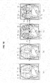
- FIG. 9 illustrates another exemplary process for horizontally dividing the screen of the display unit.
- the display unit 100 displays a general x-ray image which has been obtained by photographing the chest region of an object, and a marker 112 which is usable for indicating a division of the screen is displayed on the upper side of the screen of the display unit 100.
- the screen is divided into a first region 120 and a second region 150.
- a horizontal boundary line hb1 which passes through the marker 112 is created.
- the horizontal boundary line hb1 moves together with the marker 112 in the dragging direction of the marker 112.
- the horizontal boundary line hb1 corresponds to the boundary between the first region 120 and the second region 150.
- the screen share of the first region 120 on the screen of the display unit 100 decreases, while the screen share of the newly produced second region 150 increases.
- the proportional amount of the chest region of the object shown in the first image 121 displayed in the first region 120 also correspondingly decreases.
- the first image 121 shows the entire chest region of the object.
- drawing (c) of FIG. 9 only about a lower half of the chest region of the object is displayed via the first image 121.
- the upper half of the chest region is shown in the second image 151, which is displayed in the second region 150.
- the combination of the first region 120 displaying the first image 121 and the second region 150 displaying the second image 151 represents the entire chest region of the object, and the first image 121 and the second image 131 match with each other, thereby enabling the entire chest region of the object to be seamlessly displayed.
- the second image 151 is an x-ray image of the same region of the same object, but this image is a color x-ray image (see the drawing labeled "color" in FIG. 3 ), not a gray image.
- the color x-ray image is simply an example, and the second image 151 may include any one or more of images which may be acquired by photographing the same region of the object as that shown in the first image 121 by using different respective imaging techniques.
- the respective screen shares of the first region 120 and the second region 150 vary based on a movement of the marker 112, and thereby the proportional amounts of the regions of the object shown in the first image 121 and the second image 151 vary.
- the first image 121 and the second image 151 naturally match with each other at the horizontal boundary line hb1.
- the image obtained through coordination represents the image of the entire photographed region of the object, similarly as the image prior to dividing of the screen.
- FIG. 10 illustrates another exemplary process for horizontally dividing the screen of the display unit.
- the exemplary embodiment illustrated in FIG. 10 differs from the exemplary embodiment of FIG. 9 in that the marker 112 of the display unit 100 is touched by using a touch tool, such as a finger or a touch pen.
- the display unit 100 may use any one or more of various kinds of commonly known touchscreens in order to facilitate input of a command by touch. Other technical details except this difference are the same as those of the exemplary embodiment of FIG. 9 , and thus a description thereof will be omitted.
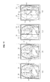
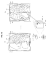
- FIGS. 11 , 12 , 13 , and 14 illustrate another exemplary embodiment for dividing the screen of the display unit.
- the display unit 100 displays a general x-ray image which is obtained by photographing the chest region of the object, and a separate marker which is usable to divide the screen is not shown.
- a vertical boundary line vb1 which passes through the click point cp1 is created, as shown in drawing (c) of FIG. 11 .
- the screen is divided into the first region 120 and the second region 130 by the vertical boundary line vb1 which is created as the boundary. While the boundary line vb1 between the first region 120 and the second region 130 is illustrated as being vertical, the boundary line may be horizontal or diagonal. To enable the user to select a desired boundary line, different manipulations for selection of respective boundary lines may be predetermined and stored.
- manipulations may be predetermined such that a vertical boundary line is created when the click point cp1 is clicked once, and a horizontal boundary line is created when the click point cp1 is clicked twice.
- the images of the object displayed in the first region 120 and the second region 130 which are created by dividing the screen are the same as those described above with reference to FIG. 2 , and thus a description thereof will be omitted.
- the screen shares of the first region 120 and the second region 130 may be adjusted simply by clicking the point cp1 at which creation of a boundary line vb1 is desired, in contrast with the exemplary embodiment of FIG. 2 in which the screen shares of the first region 120 and the second region 130 are adjusted by dragging a marker. More specifically, when a point cp2 which is different from the click point cp1 is clicked, as shown in drawing (d) of FIG. 11 , the vertical boundary line vb1 shown in drawing (c) of FIG. 11 disappears, and a new vertical boundary line vb1 which passes through the click point cp2 is created.
- the screen is divided into the first region 120 and the second region 130 by the new vertical boundary line vb1 which has been created as the boundary.
- the screen share of the first region 120 decreases and the screen share of the second region 130 increases in drawing (d) of FIG. 11 .
- a new vertical boundary line vb1 may be created, as shown in drawing (d) of FIG. 12 , in such a manner that the vertical boundary line vb1 shown in drawing (c) of FIG. 12 shifts to the position of the vertical boundary line vb1 shown in drawing (d) of FIG. 12 along a cursor which is dragged from the click point cp1 shown in drawing (c) of FIG. 12 to the click point cp1 shown in drawing (d) of FIG. 12 .
- a new click point cp2 is not created as in drawing (d) of FIG. 11 , but the click point cp1 shown in drawing (c) of FIG. 12 is shifted to create a boundary line.
- FIGS. 13 and 14 respectively illustrate dividing the screen into the same regions as in FIGS. 11 and 12 , respectively. Unlike FIG. 11 and 12 , dividing is performed by touch.
- the exemplary embodiment illustrated in FIGS. 13 and 14 differs from the exemplary embodiment of FIGS. 11 and 12 in that the display unit 100 is touched using a touch tool, such as a finger or a touch pen.
- the display unit 100 may use any one or more of various kinds of commonly known touchscreens in order to facilitate input of a command by touch. Other technical details except this difference are the same as those of the exemplary embodiment of FIGS. 11 and 12 , and thus a description thereof will be om itted.
- FIGS. 2 through 14 which illustrate that various kinds of images acquired through an x-ray apparatus are displayed in the first region 120 and the second region 130
- images which are acquired by photographing the same region of the same object by using different kinds of modalities may be displayed in the first region 120 and the second region 130.
- CT computed tomography
- PET positron emission tomography
- the image captured via CT may be displayed in the first region 120
- the image captured via PET may be displayed in the second region 130.
- the user is able to seamlessly check several images of the same region of the same object which have been photographed by using different modalities on one single display apparatus, and therefore, a more efficient and accurate diagnosis may be possible.
- FIG. 15 is a view which illustrates an example of displaying a marker and text together on the display unit.
- the text "soft” and the marker 110 are displayed together on the left side of the display unit 100 such that the user is informed that a soft tissue x-ray image is displayed in a region of the screen when the marker 110 is moved.
- the text "bone” and the marker 111 are displayed together on the right side of the display unit 100 such that the user is informed that a bone x-ray image is displayed in a region of the screen when the marker 111 is moved.
- the text "color” and the marker 112 are displayed together on the upper side of the display unit 100 such that the user is informed that a color x-ray image is displayed in a region of the screen when the marker 112 is moved.
- Displaying the texts and the markers 110, 111 and 112 together is simply an example. Alternatively, thumbnails and the markers 110, 111 and 112 may be displayed together. Any type of marking which indicates the types of images displayed in the regions 130, 160 and 150 is within the scope of this exemplary embodiment.
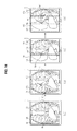
- FIGS. 16 , 17 , 18 , 19 , and 20 are views which illustrate exemplary embodiments of changing a first image and a second image, which are respectively displayed in the first region and the second region that have been divided from each other, to other images.
- windows 123 and 133 which relate to displaying a plurality of thumbnails tn1, tn2, tn3 and tn4 may be respectively formed at the lower ends of the first region 120 and the second region 130.
- the windows 123 and 133 which relate to displaying the thumbnails tn1, tn2, tn3 and tn4 may be formed not only at the lower ends of the regions, but also at other positions, such as the upper ends of the regions, or at other suitable positions.
- the thumbnails tn1, tn2, tn3 and tn4 may include thumbnails of x-ray images of the same region of an object which have captured by using various techniques.
- the x-ray images represented by the thumbnails tn1, tn2, tn3 and tn4 may be pre-stored in the memory 20 (see FIG. 1 ).
- Various thumbnails of the x-ray images such as the thumbnail tn1 of a soft tissue x-ray image, the thumbnail tn2 of a general x-ray image, the thumbnail tn3 of a bone x-ray image, and/or the thumbnail tn4 of a color x-ray image, may be displayed.
- a bone x-ray image is displayed in the first region 120
- a soft tissue x-ray image is displayed in the second region 130.
- the user may click or touch the thumbnail tn2 of the general x-ray image among the thumbnails tn1, tn2, tn3 and tn4 displayed at the lower end of the second region 130.
- the thumbnail tn2 of the general x-ray image is clicked or touched, the soft tissue x-ray image displayed in the second region 130 changes to the general x-ray image.
- the changed general x-ray image and the bone x-ray image in the first region 120 naturally match with each other at the boundary line vb1, and the image produced by the match shows the same region of the same object.
- the user may click or touch the thumbnail tn4 of the color x-ray image among the thumbnails tn1, tn2, tn3 and tn4 displayed at the lower end of the first region 120.
- the thumbnail tn4 of the color x-ray image is clicked or touched, the bone x-ray image displayed in the first region 120 is changed to the color x-ray image.
- the changed color x-ray image and the general x-ray image in the second region 130 naturally match with each other at the boundary line vb1, and the image produced by the coordination shows the same region of the same object.
- windows 124 and 134 which relate to displaying text which indicates the feature of a corresponding x-ray image to be displayed in a corresponding one of the respective regions and an icon for change of the text together may be formed at the lower ends of the first region 120 and the second region 130.
- the windows 124 and 134 which relate to displaying text may be formed not only at the lower ends of the regions, but also at other positions, such as the upper ends of the regions, or any other suitable positions.
- the user touches or clicks an icon for change of text in the window 124, 134 formed at the lower end of the first region 120 as shown in drawing (a) of FIG. 18 , and then touches or clicks text "soft" as shown in drawing (b) of FIG. 18 .
- the first image 121 which is displayed in the first region 120 changes from the bone x-ray image to the soft tissue x-ray image, as shown in drawing (c) of FIG. 18 .
- the changed soft tissue x-ray image and the general x-ray image in the second region 130 naturally match with each other at the boundary line vb1, and the image produced via the match shows the same region of the same object.
- an image may be changed by positioning a mouse in the region where the image is displayed, and then inputting a scroll command via the wheel of the mouse, or inputting a command via manipulation of arrow keys on a keyboard.
- an image may be changed by touching the region within which the image is displayed and dragging up or down the same.
- the second image 131 which is displayed in the second region 130 is sequentially changed to each of the x-ray images stored in the memory 20.
- the user may find the desired image by inputting a scroll-up command by rotating the mouse upward.
- the desired image is displayed in the second region 130 as a result of continuous input of the scroll-down command or scroll-up command until the scrolling is stopped, the image is not changed any more.
- the user may change the image which is displayed in the second region 130 not only by inputting a command via the mouse, but also by manipulating an arrow key indicating the downward direction or the upward direction among the arrow keys on the keyboard in the same manner.
- the image may be changed by manipulating the left arrow and right arrow keys.
- the illustrated mouse and keyboard are exemplary, and the image may be changed using other input methods, as described above.
- the user may change the image which is displayed in the second region 130 by directly touching the screen of the display unit 100 and dragging up or down the same with a finger or a touch pen.
- FIGS. 21 and 22 illustrate an exemplary method of enlarging and dividing an image which is displayed on the display unit.
- the user may input a command which relates to enlarging a region of interest in order to observe the region of interest by enlarging the region.
- an area to be enlarged is specified by clicking a predetermined position near the region of interest and dragging the same.
- a rectangle for which the drag line serves as a diagonal line thereof is generally created in the dragging direction.
- the rectangular area created in this way is specified as the enlargement area.
- the shape and size of the enlargement region may be directly specified by touch rather than by clicking.
- a predetermined position near the region of interest is touched, and the shape of an area to be enlarged is drawn with a finger or a touch pen.
- drawing (b) of FIG. 22 an enlargement area having a circular shape is created.
- the method for specifying an enlargement area which is illustrated in FIGS. 21 and 22 is purely exemplary, and specifying an enlargement area may be implemented by using any one or more of various methods.
- magnification factor may be preset in any one or more of various manners and stored the memory 20, and the user may select a desired magnification factor and determine an extent of enlargement of an image.
- the screen of the enlargement area may also be divided.
- images of the same region of an object which have been captured by using different respective techniques may be respectively displayed in the divided regions.
- drawing (d) of FIG. 21 and drawing (d) of FIG. 22 when any location on the screen is clicked or touched, a vertical boundary line vbe which passes through a click point cpe or a touch point tpe is created, and the screen is divided into a first region 120e and a second region 130e by the created boundary line. While the boundary line vbe between the first region 120e and the second region 130e is illustrated as being vertically created, a horizontal line or a diagonal line may alternatively be created as the boundary line.
- manipulations which correspond to selections of respective boundary lines may be predetermined and stored.
- manipulations may be predetermined such that a vertical boundary line is created when the click point is clicked once, and a horizontal boundary line is created when the click point is clicked twice.
- the enlargement area may also be divided by dragging the markers 110 and 111 which are displayed in the enlargement area, similarly as illustrated in FIG. 2 .
- Images of the same region of an object which are captured by using different respective techniques are respectively displayed in the first region 120e and the second region 130e divided by the boundary.
- a color x-ray image may be displayed in the first region 120e
- a general x-ray image may be displayed in the second region 130e.
- the markers 110 and 111 may be dragged, as illustrated in FIG. 2 , or a point in an enlargement area at which the boundary line vbe is desired to be created may be clicked or touched, as illustrated in FIGS. 11 through 14 .
- the first image 121 and the second image 131e always match with each other at the vertical boundary line vbe, regardless of changes in the respective proportional amounts shown in the first image 121e and the second image 131e.
- the method illustrated in FIGS. 16 through 20 may be applied to the first image 121e and the second image 131e as respectively displayed in the first region 120e and the second region 130e, which regions are created by dividing the enlargement area so as to change the images into different types of images.
- a user can easily and quickly check different images of a certain region of an object in an alternating manner.
- the user can seamlessly display and compare different respective types of images of a certain region of an object, which images are captured by using correspondingly different techniques, thus obtaining unique information respectively on one display apparatus, rather than on multiple display apparatuses by combining the images. Because multiple images of the same object region are simultaneously checked on one display apparatus, a resulting accuracy of diagnosis may be enhanced, and more intuitive diagnosis may be possible.
Priority Applications (3)
| Application Number | Priority Date | Filing Date | Title |
|---|---|---|---|
| EP16160808.8A EP3057017B1 (de) | 2013-10-04 | 2014-09-30 | Anzeigegerät und bildanzeigeverfahren unter verwendung desselben |
| EP17167330.4A EP3217305B1 (de) | 2013-10-04 | 2014-09-30 | Anzeigevorrichtung und anzeigeverfahren dafür |
| EP20175609.5A EP3723099A1 (de) | 2013-10-04 | 2014-09-30 | Anzeigevorrichtung und bildanzeigeverfahren mit verwendung davon |
Applications Claiming Priority (1)
| Application Number | Priority Date | Filing Date | Title |
|---|---|---|---|
| KR1020130118779A KR102244258B1 (ko) | 2013-10-04 | 2013-10-04 | 디스플레이 장치 및 이를 이용한 영상표시방법 |
Related Child Applications (3)
| Application Number | Title | Priority Date | Filing Date |
|---|---|---|---|
| EP20175609.5A Division EP3723099A1 (de) | 2013-10-04 | 2014-09-30 | Anzeigevorrichtung und bildanzeigeverfahren mit verwendung davon |
| EP16160808.8A Division EP3057017B1 (de) | 2013-10-04 | 2014-09-30 | Anzeigegerät und bildanzeigeverfahren unter verwendung desselben |
| EP17167330.4A Division EP3217305B1 (de) | 2013-10-04 | 2014-09-30 | Anzeigevorrichtung und anzeigeverfahren dafür |
Publications (1)
| Publication Number | Publication Date |
|---|---|
| EP2858000A1 true EP2858000A1 (de) | 2015-04-08 |
Family
ID=51702976
Family Applications (4)
| Application Number | Title | Priority Date | Filing Date |
|---|---|---|---|
| EP14187055.0A Ceased EP2858000A1 (de) | 2013-10-04 | 2014-09-30 | Anzeigevorrichtung und Anzeigeverfahren damit |
| EP16160808.8A Active EP3057017B1 (de) | 2013-10-04 | 2014-09-30 | Anzeigegerät und bildanzeigeverfahren unter verwendung desselben |
| EP17167330.4A Active EP3217305B1 (de) | 2013-10-04 | 2014-09-30 | Anzeigevorrichtung und anzeigeverfahren dafür |
| EP20175609.5A Pending EP3723099A1 (de) | 2013-10-04 | 2014-09-30 | Anzeigevorrichtung und bildanzeigeverfahren mit verwendung davon |
Family Applications After (3)
| Application Number | Title | Priority Date | Filing Date |
|---|---|---|---|
| EP16160808.8A Active EP3057017B1 (de) | 2013-10-04 | 2014-09-30 | Anzeigegerät und bildanzeigeverfahren unter verwendung desselben |
| EP17167330.4A Active EP3217305B1 (de) | 2013-10-04 | 2014-09-30 | Anzeigevorrichtung und anzeigeverfahren dafür |
| EP20175609.5A Pending EP3723099A1 (de) | 2013-10-04 | 2014-09-30 | Anzeigevorrichtung und bildanzeigeverfahren mit verwendung davon |
Country Status (6)
| Country | Link |
|---|---|
| US (3) | US10468134B2 (de) |
| EP (4) | EP2858000A1 (de) |
| JP (2) | JP2015076882A (de) |
| KR (1) | KR102244258B1 (de) |
| CN (3) | CN110515513B (de) |
| IN (1) | IN2014DE02767A (de) |
Families Citing this family (21)
| Publication number | Priority date | Publication date | Assignee | Title |
|---|---|---|---|---|
| US10198170B2 (en) * | 2014-02-12 | 2019-02-05 | Lg Electronics Inc. | Mobile terminal and control method therefor |
| WO2015126098A1 (en) * | 2014-02-24 | 2015-08-27 | Samsung Electronics Co., Ltd. | Method and apparatus for displaying content using proximity information |
| USD769278S1 (en) * | 2015-01-13 | 2016-10-18 | Comprehensive Telemedicine | Display screen with graphical user interface for auscultation points |
| CN106560827B (zh) * | 2015-09-30 | 2021-11-26 | 松下知识产权经营株式会社 | 控制方法 |
| CN106236118B (zh) * | 2016-07-18 | 2018-02-27 | 上海联影医疗科技有限公司 | 图像信息显示交互装置及方法 |
| USD844655S1 (en) | 2017-04-18 | 2019-04-02 | Intuitive Surgical Operations, Inc. | Display screen or portion thereof with graphical user interface |
| USD830381S1 (en) * | 2017-04-18 | 2018-10-09 | Intuitive Surgical Operations, Inc. | Display screen or portion thereof with graphical user interface |
| CN107622792B (zh) * | 2017-08-30 | 2021-12-31 | 东软医疗系统股份有限公司 | 一种医学图像显示方法及显示设备 |
| CN108255405B (zh) * | 2018-01-19 | 2019-09-10 | Oppo广东移动通信有限公司 | 用户界面显示方法、装置及终端 |
| CN108366225A (zh) * | 2018-01-26 | 2018-08-03 | 蓝网科技股份有限公司 | 基于多通道内窥镜影像采集的方法、装置、设备及存储介质 |
| KR102107893B1 (ko) * | 2018-02-14 | 2020-05-07 | 가톨릭대학교 산학협력단 | 의료용 영상 정보 판독 장치 및 판독 방법 |
| TWI686742B (zh) | 2018-10-29 | 2020-03-01 | 華碩電腦股份有限公司 | 控制方法、電子裝置及非暫態電腦可讀記錄媒體裝置 |
| CN109544539A (zh) * | 2018-11-27 | 2019-03-29 | 南京巨鲨显示科技有限公司 | 一种自适应集中显示医学影像曲线的系统及方法 |
| KR102273923B1 (ko) * | 2018-12-18 | 2021-07-06 | (주)제노레이 | 의료 영상 데이터 및 치료 데이터 관리 장치 및 방법 |
| CN109766069B (zh) * | 2019-01-15 | 2023-05-12 | 高创(苏州)电子有限公司 | 辅助显示方法、装置、电子设备及计算机可读存储介质 |
| CN111158620B (zh) * | 2019-12-26 | 2020-11-24 | 成都星时代宇航科技有限公司 | 一种图片的显示方法、装置及终端 |
| USD953373S1 (en) * | 2020-07-15 | 2022-05-31 | Vyaire Medical, Inc. | Display screen with graphical icon |
| CN112954441B (zh) * | 2021-03-02 | 2023-06-06 | 北京字节跳动网络技术有限公司 | 视频编辑及播放方法、装置、设备、介质 |
| CN113946261B (zh) * | 2021-08-30 | 2023-12-05 | 福建中红信创科技有限公司 | 一种人机交互展示方法和系统 |
| CN114816115B (zh) * | 2022-04-13 | 2023-01-17 | 安徽宝信信息科技有限公司 | 一种教育教学用屏幕辅助设备 |
| CN115793912B (zh) * | 2023-02-02 | 2023-05-26 | 苏州一目万相科技有限公司 | 图像显示方法、图像显示装置和可读存储介质 |
Citations (6)
| Publication number | Priority date | Publication date | Assignee | Title |
|---|---|---|---|---|
| EP0913807A2 (de) * | 1997-10-31 | 1999-05-06 | Lumisys Inc. | System und Verfahren zur direkten Bildmanipulation |
| US6310631B1 (en) * | 1996-04-26 | 2001-10-30 | International Business Machines Corporation | User interface control for creating split panes in a single window |
| WO2004034910A1 (en) * | 2002-10-21 | 2004-04-29 | Koninklijke Philips Electronics N.V. | System and method for improving the display of diagnostic images |
| WO2010096438A2 (en) * | 2009-02-17 | 2010-08-26 | Virtual Radiologic Corporation | Organizing medical images for display |
| US20110157154A1 (en) * | 2009-12-30 | 2011-06-30 | General Electric Company | Single screen multi-modality imaging displays |
| EP2484275A1 (de) * | 2009-09-30 | 2012-08-08 | FUJIFILM Corporation | Medizinische bildanzeigevorrichtung sowie verfahren und programm dafür |
Family Cites Families (46)
| Publication number | Priority date | Publication date | Assignee | Title |
|---|---|---|---|---|
| US5142275A (en) * | 1984-12-10 | 1992-08-25 | General Electric Company | Method and means for manipulating images in a video display |
| JPS63223968A (ja) * | 1987-03-13 | 1988-09-19 | Jeol Ltd | 画像表示装置 |
| JP2886162B2 (ja) * | 1987-10-13 | 1999-04-26 | 株式会社東芝 | 画像表示装置 |
| US5485371A (en) * | 1990-02-14 | 1996-01-16 | Fuji Photo Film Co., Ltd. | Method for forming energy subtraction radiation images, and method and apparatus for smoothing radiation images |
| JP3639030B2 (ja) * | 1995-02-28 | 2005-04-13 | 株式会社東芝 | 画像表示システム及びそのシステムを用いた画像表示方法 |
| JP3878259B2 (ja) * | 1996-11-13 | 2007-02-07 | 東芝医用システムエンジニアリング株式会社 | 医用画像処理装置 |
| US6239799B1 (en) * | 1998-06-23 | 2001-05-29 | International Business Machines Corporation | Method and system for providing a splitter bar control |
| US6195094B1 (en) * | 1998-09-29 | 2001-02-27 | Netscape Communications Corporation | Window splitter bar system |
| WO2002067039A1 (fr) * | 2001-02-19 | 2002-08-29 | Olympus Optical Co., Ltd. | Dispositif de comparaison d'images, procede de comparaison d'images et programme comportant une comparaison d'images informatisee |
| US6897880B2 (en) | 2001-02-22 | 2005-05-24 | Sony Corporation | User interface for generating parameter values in media presentations based on selected presentation instances |
| US6914958B2 (en) * | 2001-07-06 | 2005-07-05 | Ge Medical Systems Global Technology Company, Llc | Multi-plane acquisition in digital x-ray radiography |
| US7616801B2 (en) * | 2002-11-27 | 2009-11-10 | Hologic, Inc. | Image handling and display in x-ray mammography and tomosynthesis |
| US8090429B2 (en) * | 2004-06-30 | 2012-01-03 | Siemens Medical Solutions Usa, Inc. | Systems and methods for localized image registration and fusion |
| CN100393281C (zh) * | 2004-07-23 | 2008-06-11 | 株式会社东芝 | X射线计算机断层摄像装置 |
| US20060020903A1 (en) | 2004-07-26 | 2006-01-26 | Shih-Yang Wang | Window split system and method |
| JP4891577B2 (ja) * | 2004-08-30 | 2012-03-07 | 株式会社東芝 | 医用画像表示装置 |
| US20060098897A1 (en) * | 2004-11-10 | 2006-05-11 | Agfa-Gevaert | Method of superimposing images |
| EP1657679A1 (de) * | 2004-11-10 | 2006-05-17 | Agfa-Gevaert | Verfahren zur Überlagerung von Bildern |
| US7885443B2 (en) * | 2005-11-14 | 2011-02-08 | Hologic, Inc. | Facilitating temporal comparison of medical images |
| WO2007062392A2 (en) * | 2005-11-23 | 2007-05-31 | Riverain Medical Group, Llc | Computer-aided diagnosis using dual-energy subtraction images |
| JP4989166B2 (ja) * | 2006-09-14 | 2012-08-01 | ジーイー・メディカル・システムズ・グローバル・テクノロジー・カンパニー・エルエルシー | 画像診断装置 |
| US7942829B2 (en) * | 2007-11-06 | 2011-05-17 | Eigen, Inc. | Biopsy planning and display apparatus |
| JP5562525B2 (ja) * | 2008-03-04 | 2014-07-30 | 株式会社東芝 | 医用情報表示装置および医用情報表示プログラム |
| FR2928257B1 (fr) * | 2008-03-04 | 2011-01-14 | Super Sonic Imagine | Systeme electronique de visualisation a double ecran. |
| EP2109080A1 (de) * | 2008-04-09 | 2009-10-14 | IBBT vzw | Verfahren und Vorrichtung zur Bearbeitung und Darstellung von medizinischen Bildern |
| DE102009004898A1 (de) * | 2009-01-16 | 2010-08-19 | Siemens Aktiengesellschaft | Verfahren zur Darstellung zweier unterschiedlicher Bilder eines Fusionsbildes und Vorrichtung hierfür |
| US8627228B2 (en) * | 2009-05-24 | 2014-01-07 | International Business Machines Corporation | Automatic sash configuration in a GUI environment |
| US8218727B2 (en) * | 2009-09-04 | 2012-07-10 | Siemens Medical Solutions Usa, Inc. | System for medical image processing, manipulation and display |
| US8687860B2 (en) * | 2009-11-24 | 2014-04-01 | Penrad Technologies, Inc. | Mammography statistical diagnostic profiler and prediction system |
| KR101430121B1 (ko) * | 2010-04-06 | 2014-08-14 | 삼성전자주식회사 | 멀티-에너지 X-ray 시스템의 영상 처리 장치 및 그 방법 |
| JP2011224086A (ja) * | 2010-04-16 | 2011-11-10 | Morita Mfg Co Ltd | 画像処理装置、x線撮影装置、画像表示方法、画像比較方法、および画像表示プログラム |
| US8971493B2 (en) * | 2010-09-08 | 2015-03-03 | Siemens Medical Solutions Usa, Inc. | System for image scanning and acquisition with low-dose radiation |
| EP2617026A4 (de) * | 2010-09-16 | 2015-03-11 | Omnyx LLC | Bearbeitung digitaler medizinischer bilder |
| WO2012071429A1 (en) * | 2010-11-26 | 2012-05-31 | Hologic, Inc. | User interface for medical image review workstation |
| JP5102888B2 (ja) * | 2011-03-23 | 2012-12-19 | 日立アロカメディカル株式会社 | 骨診断画像表示装置 |
| JP6039203B2 (ja) * | 2011-05-23 | 2016-12-07 | キヤノン株式会社 | 画像出力装置、画像出力装置の制御方法、及び、プログラム |
| JP5628092B2 (ja) * | 2011-05-25 | 2014-11-19 | 富士フイルム株式会社 | 画像処理装置、放射線画像撮影システム、画像処理プログラム、及び画像処理装置の作動方法 |
| JP5306422B2 (ja) * | 2011-07-19 | 2013-10-02 | 株式会社東芝 | 画像表示システム、装置、方法及び医用画像診断装置 |
| JP5844576B2 (ja) * | 2011-08-31 | 2016-01-20 | サイバネットシステム株式会社 | 画像生成装置、方法、およびプログラム |
| KR101337339B1 (ko) * | 2011-10-21 | 2013-12-06 | 삼성전자주식회사 | 엑스선 영상 장치 및 그 제어방법 |
| KR101851239B1 (ko) * | 2011-11-08 | 2018-04-23 | 삼성전자 주식회사 | 휴대단말기의 이미지 표현장치 및 방법 |
| KR101474768B1 (ko) * | 2011-12-21 | 2014-12-19 | 삼성전자 주식회사 | 의료기기 및 이를 이용한 영상표시방법 |
| JP5745444B2 (ja) * | 2012-03-05 | 2015-07-08 | 富士フイルム株式会社 | 医用画像表示装置および医用画像表示方法、並びに、医用画像表示プログラム |
| US9877699B2 (en) * | 2012-03-26 | 2018-01-30 | Teratech Corporation | Tablet ultrasound system |
| KR20140017339A (ko) * | 2012-07-31 | 2014-02-11 | 삼성전자주식회사 | 엑스선 촬영 장치 및 엑스선 촬영 장치의 촬영 영역 설정 방법 |
| KR20150066963A (ko) * | 2013-12-09 | 2015-06-17 | 삼성전자주식회사 | 의료 영상 배치 방법 및 이를 위한 의료 기기 |
-
2013
- 2013-10-04 KR KR1020130118779A patent/KR102244258B1/ko active IP Right Grant
-
2014
- 2014-09-26 IN IN2767DE2014 patent/IN2014DE02767A/en unknown
- 2014-09-26 JP JP2014197324A patent/JP2015076882A/ja active Pending
- 2014-09-30 EP EP14187055.0A patent/EP2858000A1/de not_active Ceased
- 2014-09-30 EP EP16160808.8A patent/EP3057017B1/de active Active
- 2014-09-30 EP EP17167330.4A patent/EP3217305B1/de active Active
- 2014-09-30 EP EP20175609.5A patent/EP3723099A1/de active Pending
- 2014-10-03 US US14/505,686 patent/US10468134B2/en active Active
- 2014-10-08 CN CN201910807347.XA patent/CN110515513B/zh active Active
- 2014-10-08 CN CN201410525012.6A patent/CN104516627B/zh active Active
- 2014-10-08 CN CN201910807427.5A patent/CN110517758A/zh active Pending
-
2015
- 2015-12-11 US US14/966,087 patent/US10622108B2/en active Active
-
2020
- 2020-03-12 US US16/816,894 patent/US10937544B2/en active Active
- 2020-09-25 JP JP2020161359A patent/JP7045432B2/ja active Active
Patent Citations (6)
| Publication number | Priority date | Publication date | Assignee | Title |
|---|---|---|---|---|
| US6310631B1 (en) * | 1996-04-26 | 2001-10-30 | International Business Machines Corporation | User interface control for creating split panes in a single window |
| EP0913807A2 (de) * | 1997-10-31 | 1999-05-06 | Lumisys Inc. | System und Verfahren zur direkten Bildmanipulation |
| WO2004034910A1 (en) * | 2002-10-21 | 2004-04-29 | Koninklijke Philips Electronics N.V. | System and method for improving the display of diagnostic images |
| WO2010096438A2 (en) * | 2009-02-17 | 2010-08-26 | Virtual Radiologic Corporation | Organizing medical images for display |
| EP2484275A1 (de) * | 2009-09-30 | 2012-08-08 | FUJIFILM Corporation | Medizinische bildanzeigevorrichtung sowie verfahren und programm dafür |
| US20110157154A1 (en) * | 2009-12-30 | 2011-06-30 | General Electric Company | Single screen multi-modality imaging displays |
Also Published As
| Publication number | Publication date |
|---|---|
| US10468134B2 (en) | 2019-11-05 |
| CN110515513A (zh) | 2019-11-29 |
| KR102244258B1 (ko) | 2021-04-27 |
| IN2014DE02767A (de) | 2015-06-26 |
| EP3723099A1 (de) | 2020-10-14 |
| EP3217305A1 (de) | 2017-09-13 |
| KR20150041221A (ko) | 2015-04-16 |
| CN104516627A (zh) | 2015-04-15 |
| JP2015076882A (ja) | 2015-04-20 |
| US20200211702A1 (en) | 2020-07-02 |
| CN104516627B (zh) | 2019-09-24 |
| US20150097869A1 (en) | 2015-04-09 |
| JP7045432B2 (ja) | 2022-03-31 |
| CN110517758A (zh) | 2019-11-29 |
| US20160098529A1 (en) | 2016-04-07 |
| JP2021020075A (ja) | 2021-02-18 |
| EP3057017A1 (de) | 2016-08-17 |
| EP3217305B1 (de) | 2020-05-27 |
| US10622108B2 (en) | 2020-04-14 |
| EP3057017B1 (de) | 2021-05-26 |
| US10937544B2 (en) | 2021-03-02 |
| CN110515513B (zh) | 2023-04-18 |
Similar Documents
| Publication | Publication Date | Title |
|---|---|---|
| US10937544B2 (en) | Medical imaging apparatus for displaying x-ray images of different types | |
| US10229753B2 (en) | Systems and user interfaces for dynamic interaction with two-and three-dimensional medical image data using hand gestures | |
| US20130093781A1 (en) | Examination information display device and method | |
| US8131028B2 (en) | Method and apparatus providing flexible measurement functionality for medical images | |
| US11169693B2 (en) | Image navigation | |
| CN112740285A (zh) | 在虚拟环境中对医学图像的叠加和操纵 | |
| US20090037840A1 (en) | Location Determination For Z-Direction Increments While Viewing Medical Images | |
| JP2018175216A (ja) | 医用画像表示装置及びプログラム | |
| CN106445435A (zh) | 医用图像显示装置、系统和方法 | |
| US10185805B2 (en) | Medical image processing apparatus and method | |
| US10324582B2 (en) | Medical image display apparatus, method for controlling the same | |
| US11460990B2 (en) | Precise positioning of a marker on a display | |
| US10531852B2 (en) | Display for converting medical images and method of use | |
| KR101611484B1 (ko) | 의료영상의 제공방법 | |
| JP7172093B2 (ja) | コンピュータプログラム、表示装置、表示システム及び表示方法 | |
| CN108231162B (zh) | 用于显示医学图像的方法和装置 | |
| KR20220026236A (ko) | 의료 영상 분석 보조 시스템, 화면을 갖는 전자 장치에서 수행되는 방법, 화면을 갖는 전자 장치의 그래픽 사용자 인터페이스 | |
| KR20210012492A (ko) | 의료 영상 분석 보조 시스템, 화면을 갖는 전자 장치에서 수행되는 방법, 화면을 갖는 전자 장치의 그래픽 사용자 인터페이스 |
Legal Events
| Date | Code | Title | Description |
|---|---|---|---|
| PUAI | Public reference made under article 153(3) epc to a published international application that has entered the european phase |
Free format text: ORIGINAL CODE: 0009012 |
|
| 17P | Request for examination filed |
Effective date: 20140930 |
|
| AK | Designated contracting states |
Kind code of ref document: A1 Designated state(s): AL AT BE BG CH CY CZ DE DK EE ES FI FR GB GR HR HU IE IS IT LI LT LU LV MC MK MT NL NO PL PT RO RS SE SI SK SM TR |
|
| AX | Request for extension of the european patent |
Extension state: BA ME |
|
| R17P | Request for examination filed (corrected) |
Effective date: 20150515 |
|
| RBV | Designated contracting states (corrected) |
Designated state(s): AL AT BE BG CH CY CZ DE DK EE ES FI FR GB GR HR HU IE IS IT LI LT LU LV MC MK MT NL NO PL PT RO RS SE SI SK SM TR |
|
| 17Q | First examination report despatched |
Effective date: 20151106 |
|
| APBK | Appeal reference recorded |
Free format text: ORIGINAL CODE: EPIDOSNREFNE |
|
| APBN | Date of receipt of notice of appeal recorded |
Free format text: ORIGINAL CODE: EPIDOSNNOA2E |
|
| APAV | Appeal reference deleted |
Free format text: ORIGINAL CODE: EPIDOSDREFNE |
|
| APBT | Appeal procedure closed |
Free format text: ORIGINAL CODE: EPIDOSNNOA9E |
|
| STAA | Information on the status of an ep patent application or granted ep patent |
Free format text: STATUS: THE APPLICATION HAS BEEN REFUSED |
|
| 18R | Application refused |
Effective date: 20170421 |