EP2857907A2 - Antriebsvorrichtung - Google Patents
Antriebsvorrichtung Download PDFInfo
- Publication number
- EP2857907A2 EP2857907A2 EP14186780.4A EP14186780A EP2857907A2 EP 2857907 A2 EP2857907 A2 EP 2857907A2 EP 14186780 A EP14186780 A EP 14186780A EP 2857907 A2 EP2857907 A2 EP 2857907A2
- Authority
- EP
- European Patent Office
- Prior art keywords
- gear
- unit
- cam unit
- conveyance screw
- rotations
- Prior art date
- Legal status (The legal status is an assumption and is not a legal conclusion. Google has not performed a legal analysis and makes no representation as to the accuracy of the status listed.)
- Granted
Links
- 238000006073 displacement reaction Methods 0.000 claims abstract description 30
- 238000004140 cleaning Methods 0.000 description 13
- 238000006243 chemical reaction Methods 0.000 description 3
- 238000010586 diagram Methods 0.000 description 2
- 238000011144 upstream manufacturing Methods 0.000 description 2
- 230000015572 biosynthetic process Effects 0.000 description 1
- 239000004568 cement Substances 0.000 description 1
- 238000003780 insertion Methods 0.000 description 1
- 230000037431 insertion Effects 0.000 description 1
- 239000000463 material Substances 0.000 description 1
- 230000003287 optical effect Effects 0.000 description 1
- 239000011347 resin Substances 0.000 description 1
- 229920005989 resin Polymers 0.000 description 1
Images








Classifications
-
- B—PERFORMING OPERATIONS; TRANSPORTING
- B65—CONVEYING; PACKING; STORING; HANDLING THIN OR FILAMENTARY MATERIAL
- B65G—TRANSPORT OR STORAGE DEVICES, e.g. CONVEYORS FOR LOADING OR TIPPING, SHOP CONVEYOR SYSTEMS OR PNEUMATIC TUBE CONVEYORS
- B65G33/00—Screw or rotary spiral conveyors
- B65G33/24—Details
- B65G33/34—Applications of driving gear
-
- G—PHYSICS
- G03—PHOTOGRAPHY; CINEMATOGRAPHY; ANALOGOUS TECHNIQUES USING WAVES OTHER THAN OPTICAL WAVES; ELECTROGRAPHY; HOLOGRAPHY
- G03G—ELECTROGRAPHY; ELECTROPHOTOGRAPHY; MAGNETOGRAPHY
- G03G21/00—Arrangements not provided for by groups G03G13/00 - G03G19/00, e.g. cleaning, elimination of residual charge
- G03G21/10—Collecting or recycling waste developer
- G03G21/105—Arrangements for conveying toner waste
-
- F—MECHANICAL ENGINEERING; LIGHTING; HEATING; WEAPONS; BLASTING
- F16—ENGINEERING ELEMENTS AND UNITS; GENERAL MEASURES FOR PRODUCING AND MAINTAINING EFFECTIVE FUNCTIONING OF MACHINES OR INSTALLATIONS; THERMAL INSULATION IN GENERAL
- F16H—GEARING
- F16H1/00—Toothed gearings for conveying rotary motion
- F16H1/02—Toothed gearings for conveying rotary motion without gears having orbital motion
- F16H1/04—Toothed gearings for conveying rotary motion without gears having orbital motion involving only two intermeshing members
- F16H1/06—Toothed gearings for conveying rotary motion without gears having orbital motion involving only two intermeshing members with parallel axes
-
- G—PHYSICS
- G03—PHOTOGRAPHY; CINEMATOGRAPHY; ANALOGOUS TECHNIQUES USING WAVES OTHER THAN OPTICAL WAVES; ELECTROGRAPHY; HOLOGRAPHY
- G03G—ELECTROGRAPHY; ELECTROPHOTOGRAPHY; MAGNETOGRAPHY
- G03G21/00—Arrangements not provided for by groups G03G13/00 - G03G19/00, e.g. cleaning, elimination of residual charge
- G03G21/16—Mechanical means for facilitating the maintenance of the apparatus, e.g. modular arrangements
- G03G21/1642—Mechanical means for facilitating the maintenance of the apparatus, e.g. modular arrangements for connecting the different parts of the apparatus
- G03G21/1647—Mechanical connection means
-
- G—PHYSICS
- G03—PHOTOGRAPHY; CINEMATOGRAPHY; ANALOGOUS TECHNIQUES USING WAVES OTHER THAN OPTICAL WAVES; ELECTROGRAPHY; HOLOGRAPHY
- G03G—ELECTROGRAPHY; ELECTROPHOTOGRAPHY; MAGNETOGRAPHY
- G03G2221/00—Processes not provided for by group G03G2215/00, e.g. cleaning or residual charge elimination
- G03G2221/16—Mechanical means for facilitating the maintenance of the apparatus, e.g. modular arrangements and complete machine concepts
- G03G2221/1651—Mechanical means for facilitating the maintenance of the apparatus, e.g. modular arrangements and complete machine concepts for connecting the different parts
- G03G2221/1657—Mechanical means for facilitating the maintenance of the apparatus, e.g. modular arrangements and complete machine concepts for connecting the different parts transmitting mechanical drive power
Definitions
- the technology of the present disclosure relates to a drive apparatus that drives an axial conveyance screw arranged within a case.
- the above-described conveyance screw is driven via a gear mechanism by a motor, for example.
- the gear mechanism has, for example, a drive gear linked to a motor and a driven gear that is fixed to one end of the conveyance screw and meshes with the drive gear.
- a drive apparatus is a drive apparatus that drives an axial conveyance screw arranged within a case.
- the drive apparatus is provided with a first gear, a second gear, a third gear, a first support member, and a second support member.
- the first gear is fixed to the conveyance screw.
- the second gear is arranged in tandem with the first gear in an axial-center direction of the conveyance screw.
- the third gear meshes with the first gear and the second gear to impart a drive power to the both gears.
- the first support member supports the first gear to enable movement in one radial direction.
- the second support member supports the second gear to disable movement in a radial direction.
- the number of teeth of the first gear is different from the number of teeth of the second gear, and a side surface at the second gear side in the first gear is formed with a first cam unit that protrudes toward the second gear side.
- a side surface at the first gear side in the second gear is formed with a second cam unit that protrudes toward the first gear side.
- Fig. 1 is a cross-sectional view showing a schematic configuration of a laser printer 1 as an image forming apparatus in the present embodiment.
- a laser printer 1 is provided with a box-like printer body 2, a manual paper feed unit 6, a cassette paper feed unit 7, an image forming unit 8, a fixing unit 9, and a paper discharge unit 10, as shown in Fig. 1 .
- the laser printer 1 is configured to convey a paper along a conveying path L within the printer body 2 so as to form an image on the paper on the basis of image data transmitted from a terminal not shown or the like.
- the manual paper feed unit 6 includes a manual insertion tray 4, which can be opened and closed, arranged in one side part of the printer body 2, and a paper feed roller 5, for manual feed, rotatably arranged inside the printer body 2.
- the cassette paper feed unit 7 is arranged at the bottom of the printer body 2.
- the cassette paper feed unit 7 includes a paper feeding cassette 11 that houses a plurality of papers placed on top of one another, a pick roller 12 that takes out each paper housed in the paper feeding cassette 11, and a feed roller 13 and a retard roller 14 with which the taken-out papers are separated paper by paper and fed to the conveying path L.
- the image forming unit 8 is arranged above the cassette paper feed unit 7 within the printer body 2.
- the image forming unit 8 is provided with a photosensitive drum 16, as an image carrier, arranged rotatably within the printer body 2, a charger 17 disposed around the photosensitive drum 16, a developing unit 18, a transfer roller 19, a cleaning unit 20, a laser scanning unit (LSU) 30, which is an optical scanner, disposed above the photosensitive drum 16, and a toner hopper 21.
- LSU laser scanning unit
- the conveying path L has a pair of resist rollers 15 that temporarily keeps the fed paper waiting and then supplies the paper to the image forming unit 8 at a predetermined timing.
- the fixing unit 9 is arranged at one side of the image forming unit 8.
- the fixing unit 9 is provided with a fixing roller 22 and a pressing roller 23 which are pressed against each other and rotated.
- the fixing unit 9 is configured to fix a toner image, which is transferred to the paper by the image forming unit 8, to the paper.
- the paper discharge unit 10 is arranged above the fixing unit 9.
- the paper discharge unit 10 is provided with a paper discharge tray 3, a pair of paper discharge rollers 24 used for conveying the paper to the paper discharge tray 3, and a plurality of conveyance guide ribs 25 that guide the paper to the paper discharge rollers 24.
- the paper discharge tray 3 is formed to be recessed at an upper portion of the printer body 2.
- the photosensitive drum 16 is rotationally driven in the image forming unit 8 and the surface of the photosensitive drum 16 is electrically charged by the charger 17.
- laser light is emitted from the laser scanning unit 30 toward the photosensitive drum 16.
- An electrostatic latent image is formed on the surface of the photosensitive drum 16 by the irradiation of the laser light.
- the electrostatic latent image formed on the photosensitive drum 16 is developed by the developing unit 18 into a visible image as a toner image.
- the paper is pressed against the surface of the photosensitive drum 16 by the transfer roller 19.
- the toner image of the photosensitive drum 16 is transferred to the paper.
- the paper to which the toner image is transferred is heated and pressed by the fixing roller 22 and the pressing roller 23 in the fixing unit 9. As a result, the toner image is fixed to the paper.
- the cleaning unit 20 is provided with a cleaning case 20a, a friction roller 20b disposed within the cleaning case 20a, and a cleaning blade 20c. Then, the remaining toner adhering to the surface of the photosensitive drum 16 is dropped by the friction roller 20b and the cleaning blade 20c into the cleaning case 20a. The remaining toner dropped in this way to within the cleaning case 20a is conveyed by the toner conveying device 31 to a toner collection container 26.
- the toner conveying device 31 includes a conveyance case 32 that links the cleaning case 20a and the toner collection container 26, an axial conveyance screw 33 disposed within the conveyance case 32, and a drive apparatus 40 (see Fig. 2 ) used for driving the conveyance screw 33.
- the conveyance case 32 is formed to be a pipe-like form (hollow cylindrical shape).
- One end of the conveyance case 32 is formed with a toner receiving port 32a that opens toward above and receives the toner dropped from the cleaning case 20a.
- the other end of the conveyance case 32 is formed with a toner discharge port 32b which opens toward below and from which the toner is discharged to the toner collection container 26.
- the one end of the conveyance case 32 opens, and the conveyance screw 33 is inserted from one end side of the conveyance case 32 into the case 32.
- the other end side of the conveyance case 32 is closed by a lateral wall 32c.
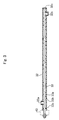
- the conveyance screw 33 includes an axial unit 33a, a spiral blade unit 33b formed along an outer circumferential surface of the axial unit 33a, and a flange unit 33c formed closer to one end of the axial unit 33a.
- the conveyance screw 33 rotates, the toner is conveyed from one end side in the axial-center direction of the conveyance screw 33 toward the other end side.
- One end side of the axial unit 33a (upstream side in a toner conveyance direction) is protruded toward outside the conveyance case 32, and the protruded portion is linked to the drive apparatus 40 for driving the conveyance screw 33.
- the flange unit 33c functions as a regulation unit that regulates the position in an axial direction of the conveyance screw 33 by abutting one end surface within the conveyance case 32, and functions also as a lid portion that closes the one end side of the conveyance case 32.
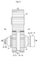
- the drive apparatus 40 includes a first gear 41 fixed to the conveyance screw 33 so as to rotate together with the conveyance screw 33, a second gear 42 arranged in tandem with the first gear 41 in an axial-center direction of the conveyance screw33, and a third gear 43 that meshes with the first gear 41 and the second gear 42 to impart a drive power to the both gears 41 and 42.
- Each gear 41 to 43 is configured by a resin material, for example.
- the first gear 41 includes a first gear body unit 41a, of substantially circular plate shape, where gear teeth are formed along the outer circumferential portion, a first cam unit 41b protruded from a surface at the second gear 42 side in the first gear body unit 41a, and a tubular axis unit 41c protruded from the opposite surface of the second gear 42 side in the first gear body unit 41a.
- a fitting hole 41f of substantially D-lettered shape is formed.
- a D cut unit 33f formed at one end side of the axial unit 33a of the conveyance screw 33 is fitted into the fitting hole 41f.
- the conveyance screw 33 is rotated together with the first gear body unit 41a (first gear 41).
- a surface at the second gear side of the first gear body unit 41a abuts a vertical surface 33g generated by the formation of the D cut unit 33f in the axial unit 33a.
- the first gear body unit 41a is locked to the axial unit 33a by a snap ring (not shown) fit into a ring groove 33h of the axial unit 33a.
- the first cam unit 41b is formed in a cylindrical shape that is coaxial with the first gear body unit 41a.
- An inner circumferential surface of the first cam unit 41b functions as a cam surface that abuts (linearly contacts) an outer circumferential surface of the second cam unit 42b of the second gear 42.
- the tubular axis unit 41c of the first gear 41 is supported rotationally by a first bearing 44 ( a first support member) to enable vertical movement (movement in one radial direction the first gear).
- the first bearing 44 includes a longhole-shaped bearing hole 44f extending vertically (see Fig. 6 and Fig. 7 ), and the tubular axis unit 41c is fitted to enable sliding vertically relative to the bearing hole 44f.
- the first bearing 44 is fixed to a fixing bracket 2a attached to the printer body 2.
- the second gear 42 includes a second gear body unit 42a, of substantially circular plate shape, where gear teeth are formed along the outer circumferential portion, a second cam unit 42b and a tubular frame unit 42c protruded from a surface at the first gear 41 side in the second gear body unit 42a and a tubular axis unit 42d protruded from the opposite surface of the first gear 41 side in the second gear body unit 42a.
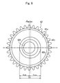
- the second cam unit 42b is formed in a cylindrical shape that is eccentric to the axial center of the second gear body unit 42a.
- An outer circumferential surface of the second cam unit 42b functions as a cam surface that abuts (linearly contacts) an inner circumferential surface of a tubular cam unit 41a of the first gear 41.
- ⁇ in Fig. 9 indicates an amount of eccentricity of the second cam unit 42b.
- the tubular frame unit 42c of the second gear 42 is formed in a cylindrical shape that is coaxial with the second gear body unit 42a.
- the tubular frame unit 42c is disposed concentrically radially outward of the second cam unit 42b, when viewed from the axial-center direction of the second gear body unit 42a.
- the first cam unit 41b of the first gear 41 is positioned between the tubular frame unit 42c and the second cam unit 42b.
- the tubular axis unit 42d of the second gear 42 is supported rotationally by a second bearing 45 ( a second support member) so that the tubular axis unit 42d is not capable of making a radial movement. That is, the second bearing 45 has a cylindrical bearing hole 45f, and the outer circumferential surface of the tubular axis unit 42d is fitted to the inner circumferential surface of the bearing hole 45f.
- the second bearing 45 is fixed to a fixing bracket 2b attached to the printer body 2.
- a hollow hole 42f of the tubular axis unit 42d penetrates through the second gear body unit 42a. Through the hollow hole 42f, the axial unit 33a of the conveyance screw 33 penetrates.
- the inner diameter of the hollow hole 42f is set sufficiently large so as not to interfere with the inner wall surface of the tubular axis unit 42d when the conveyance screw 33 is displaced downward as described below.
- the third gear 43 is linked to a motor (not shown) attached to the printer body 2.
- the third gear 43 is supported rotationally by a shaft (not shown) fixed to the printer body 2. Then, the drive power of the motor is transmitted via the third gear 43 to the first gear 41 and the second gear 42.
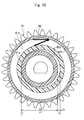
- an energizing spring 50 is arranged between the tubular frame unit 42c of the second gear and the first cam unit 41b of the first gear 41.
- the energizing spring 50 is configured to energize in a direction in which the first cam unit 41b is pressed against the second cam unit 42b.
- the energizing spring 50 is disposed to abut the upper end of the first cam unit 41b when a maximum radial part of the second cam unit 42b abuts the end of a horizontal one side (left side of Fig. 10 ) in the inner circumferential surface of the first cam unit 41b. In this state, the energizing spring 50 is configured to energize the first cam unit 41b downward.
- the number of teeth of the first gear 41 and that of the second gear 42 are different.
- the number of teeth of the first gear 41 is 33 and the number of teeth of the second gear 42 is 32. That is, the number of teeth of the first gear 41 is greater by one than the number of teeth of the second gear 42.
- the number of teeth of the third gear 43 is the same, that is, 33, as that of the first gear 41, for example.
- the number of teeth of the first gear 41 is configured to be greater by one than the number of teeth of the second gear 42, there occurs a circumferential phase difference between the first gear 41 and the second gear 42 along with the rotation of the third gear 43.
- the second gear 42 (number of teeth: 32) advances by one tooth in a circumferential direction relative to the first gear 41 (number of teeth: 33) (see Fig. 11 ). Therefore, when the third gear 43 makes 32 rotations, the second gear 42 advances by 32 teeth relative to the first gear 41, that is, by angle 2n in the circumferential direction.
- the first cam unit 41b and the second cam unit 42b are configured to work together to convert, in a predetermined period, a circumferential relative displacement between the first gear 41 and the second gear 42 generated when the third gear 43 rotates, into a vertical displacement (displacement in one radial direction of the first gear 41) of the first gear 41.
- Fig. 12 are explanatory diagrams each describing the conversion logic.
- Fig. 12A shows an initial state
- Figs. 12B, 12C, and 12D show states where advance angles (phase in a clockwise direction in the figures) of the second gear 42 relative to the first gear 41 are ⁇ /2(rad), ⁇ (rad), and 3 ⁇ /2(rad) relative to the initial state.
- the first cam unit 41b is displaced downward by the energizing force from the energizing spring 50 such that a minimum eccentric part of the second cam unit 42b abuts the inner circumferential surface of the first cam unit 41b (that is, such that no gap K is generated between the second cam unit 42b and the first cam unit 41b).
- a position of the rotation axial center of the first gear 41 is displaced downward.
- Fig. 13 to Fig. 15 each show a change (left-side column of each figure) in a phase position of the teeth of the second gear 42 when the number of rotations of the third gear 43 increases by every four rotations up to 32 rotations and a change (right-side column of each figure) in a contact position of the both cam units 41b and 42b.
- the left-side column of each figure corresponds to a cross-sectional view along line A-A of Fig. 5
- the right-side column of each figure corresponds to an arrow view in a direction B in Fig. 5 .
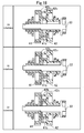
- the first gear 41 and the conveyance screw 33 are linked to make an integrated rotation together, and thus, when the first gear 41 is displaced downward, the conveyance screw 33 also is displaced downward.
- Fig. 16 to Fig. 18 each show a state where the conveyance screw 33 is moved upward and downward along with the displacement of the first gear 41.
- Fig. 19 is a graph showing a relationship between the number of rotations of the third gear 43 and a downward displacement amount of the first gear 41.
- An actual line of the graph is a line obtained by plotting a downward displacement amount of the first gear 41 when the number of rotations of the third gear 43 is 1, 2, 3, ... , that is, the integral number of rotations, and linking each plotted point (not shown) on a curve.
- the graph reveals that a state where the downward displacement amount of the first gear 41 is constant, that is, 0, and a state where the downward displacement amount of the first gear 41 exceeds 0 (state where the first gear 41 is displaced downward relative to the initial state) are repeated alternatingly when the third gear 43 makes 16 rotations.
- the downward displacement amount of the first gear 41 changes periodically in a predetermined period in accordance with the number of rotations of the third gear 43.
- the graph also reveals that a movement profile of the first gear 41 during displacement is very smooth.
- a two-dot chain line of the graph is a line schematically depicting a downward displacement amount of the first gear 41 between respective plots described above (not shown). The reason why no displacement profile is depicted below the horizontal axis of the graph (that is, in a region showing an upward displacement of the first gear 41) is because the upward displacement of the first gear 41 is restricted by the upper end of the bearing hole 44f (see Fig. 7 ).
- the conveyance screw 33 is displaced downward periodically, and therefore, even when a clearance between the conveyance screw 33 and the inner wall surface of the conveyance case 32 is large, it is possible to convey a toner while ensuring that the toner remaining in the lower end within the conveyance case 32 is scratched by the conveyance screw 33. Further, when the clearance is large, it becomes possible to restrain the interference between the outer diameter part of the conveyance screw 33 and the inner wall surface of the conveyance case 32 so that noise is prevented from being generated.
- the drive apparatus 40 is linked to the upstream end in a toner conveyance direction of the conveyance screw 33; however, this is not limiting, and the drive apparatus 40 may be linked to the downstream end in a toner conveyance direction of the conveyance screw 33, for example.
- the circumferential relative displacement, between the first gear 41 and the second gear 42, generated when the third gear 43 rotates, is converted, by the drive apparatus 40, into a vertical displacement (displacement in one radial direction of the first gear 41) of the first gear 41; however, this is not limiting and the circumferential relative displacement may be converted into a displacement in a horizontal direction of the first gear 41, for example.
- the first cam unit 41b is configured by the cylindrical cam unit and the second cam unit 42b is configured by the cylindrical eccentric cam unit; however, the cam shape of each cam unit is not limited thereto. That is, the cam shape may be any shape to enable conversion of a circumferential relative displacement, generated along with rotation of the third gear 43, between the first gear 41 and the second gear 42, into a displacement in one radial direction of the first gear 41.
- the energizing spring 50 is arranged between the tubular frame unit 42c and the first cam unit 41b; however, the energizing spring 50 may not necessarily be needed. That is, the first gear 41 may be displaced downward by its weight, without arranging the energizing spring 50.
- the toner case 32 is formed in a pipe-like shape; however, this is not limiting and the toner case 32 may be in a container-like shape of which the top opens, for example.
- the first gear 41 is different in number of teeth from the second gear 42 by one tooth; however, naturally, the difference may be two or more.
- the number of teeth of the third gear 43 is set equally to the number of teeth of the first gear 41, that is, 33 teeth; however, this is not limiting and the number of teeth may be 32 or less, and naturally, the number of teeth may be 34 or more.
- an item to be conveyed by the conveyance screw 33 is toner; however, the item to be conveyed may be cement, etc., as well as toner.
- the technology of the present disclosure is useful for a drive apparatus that drives an axial conveyance screw arranged in a case, and in particular, is useful when it is applied to a conveyance screw for toner conveyance used in an electrophotographic image forming apparatus.
Landscapes
- Engineering & Computer Science (AREA)
- Physics & Mathematics (AREA)
- General Physics & Mathematics (AREA)
- General Engineering & Computer Science (AREA)
- Mechanical Engineering (AREA)
- Life Sciences & Earth Sciences (AREA)
- Environmental & Geological Engineering (AREA)
- Sustainable Development (AREA)
- Electrophotography Configuration And Component (AREA)
- Cleaning In Electrography (AREA)
- Transmission Devices (AREA)
Applications Claiming Priority (1)
| Application Number | Priority Date | Filing Date | Title |
|---|---|---|---|
| JP2013209502A JP5873060B2 (ja) | 2013-10-04 | 2013-10-04 | 駆動装置 |
Publications (3)
| Publication Number | Publication Date |
|---|---|
| EP2857907A2 true EP2857907A2 (de) | 2015-04-08 |
| EP2857907A3 EP2857907A3 (de) | 2015-04-22 |
| EP2857907B1 EP2857907B1 (de) | 2016-09-28 |
Family
ID=51625913
Family Applications (1)
| Application Number | Title | Priority Date | Filing Date |
|---|---|---|---|
| EP14186780.4A Not-in-force EP2857907B1 (de) | 2013-10-04 | 2014-09-29 | Antriebsvorrichtung |
Country Status (4)
| Country | Link |
|---|---|
| US (1) | US9199798B2 (de) |
| EP (1) | EP2857907B1 (de) |
| JP (1) | JP5873060B2 (de) |
| CN (1) | CN104514844B (de) |
Families Citing this family (4)
| Publication number | Priority date | Publication date | Assignee | Title |
|---|---|---|---|---|
| US20150257338A1 (en) * | 2014-03-14 | 2015-09-17 | Deere & Company | Agricultural harvester with bevel gear drive |
| JP6539514B2 (ja) * | 2015-06-23 | 2019-07-03 | 株式会社三共製作所 | 内接カムと円筒ピニオンを用いた動力伝達装置 |
| JP6692516B2 (ja) * | 2017-03-23 | 2020-05-13 | 京セラドキュメントソリューションズ株式会社 | トナー搬送装置及び該トナー搬送装置を備えた画像形成装置 |
| CN107397233A (zh) * | 2017-08-07 | 2017-11-28 | 宁德职业技术学院 | 一种鲜魔芋打浆成泥机 |
Family Cites Families (14)
| Publication number | Priority date | Publication date | Assignee | Title |
|---|---|---|---|---|
| US2765899A (en) * | 1952-04-29 | 1956-10-09 | Wallace & Tiernan Inc | Dry feeder |
| PT65597B (de) * | 1975-10-11 | 1978-03-28 | Balcke Duerr Ag | Planetengetriebe |
| US4285159A (en) * | 1980-02-25 | 1981-08-25 | Mattel, Inc. | Direction reversing crib toy |
| JPH103239A (ja) * | 1996-06-14 | 1998-01-06 | Ricoh Co Ltd | 画像形成装置のトナー搬出装置 |
| JP3700842B2 (ja) * | 2001-11-28 | 2005-09-28 | 京セラ株式会社 | 画像形成機の残留トナー回収装置 |
| JP2006143406A (ja) * | 2004-11-19 | 2006-06-08 | Kobe Steel Ltd | スクリュー式搬送装置およびその運転制御方法、ならびに移動炉床炉用スクリュー式排出装置の運転制御方法 |
| KR100653086B1 (ko) * | 2005-01-21 | 2006-12-01 | 삼성전자주식회사 | 폐토너 분쇄장치 및 이를 구비한 토너 카트리지 |
| JP4980731B2 (ja) | 2007-01-15 | 2012-07-18 | 京セラドキュメントソリューションズ株式会社 | トナーコンテナ |
| JP5124261B2 (ja) * | 2007-12-26 | 2013-01-23 | 京セラドキュメントソリューションズ株式会社 | 画像形成装置 |
| JP5527010B2 (ja) * | 2009-10-02 | 2014-06-18 | 株式会社リコー | 粉体搬送装置及び画像形成装置 |
| JP5639454B2 (ja) * | 2010-12-03 | 2014-12-10 | キヤノン株式会社 | トナー回収装置及び画像形成装置 |
| JP5323043B2 (ja) * | 2010-12-24 | 2013-10-23 | 京セラドキュメントソリューションズ株式会社 | 画像形成装置 |
| JP5538284B2 (ja) * | 2011-03-29 | 2014-07-02 | 京セラドキュメントソリューションズ株式会社 | 画像形成装置 |
| JP5736919B2 (ja) * | 2011-04-06 | 2015-06-17 | 株式会社リコー | 廃トナー回収容器、及び、画像形成装置 |
-
2013
- 2013-10-04 JP JP2013209502A patent/JP5873060B2/ja not_active Expired - Fee Related
-
2014
- 2014-09-23 US US14/493,698 patent/US9199798B2/en not_active Expired - Fee Related
- 2014-09-28 CN CN201410506691.2A patent/CN104514844B/zh not_active Expired - Fee Related
- 2014-09-29 EP EP14186780.4A patent/EP2857907B1/de not_active Not-in-force
Non-Patent Citations (1)
| Title |
|---|
| None |
Also Published As
| Publication number | Publication date |
|---|---|
| EP2857907B1 (de) | 2016-09-28 |
| JP2015075502A (ja) | 2015-04-20 |
| US20150096868A1 (en) | 2015-04-09 |
| US9199798B2 (en) | 2015-12-01 |
| CN104514844A (zh) | 2015-04-15 |
| EP2857907A3 (de) | 2015-04-22 |
| CN104514844B (zh) | 2017-04-12 |
| JP5873060B2 (ja) | 2016-03-01 |
Similar Documents
| Publication | Publication Date | Title |
|---|---|---|
| JP5745159B2 (ja) | 粉体搬送装置及び画像形成装置 | |
| EP2857907B1 (de) | Antriebsvorrichtung | |
| KR101430535B1 (ko) | 토너 보급 장치 및 화상 형성 장치 | |
| CN112631095B (zh) | 显影盒 | |
| US9008543B2 (en) | Image forming apparatus | |
| US8401435B2 (en) | Developer supplying apparatus | |
| EP2574987B1 (de) | Kraftübertragungs-Körpermontagestruktur und Tonertransportvorrichtung | |
| JP6137029B2 (ja) | カートリッジ | |
| JP2011158507A (ja) | シャッタ開閉機構及びこれを備えた画像形成装置 | |
| US9188938B2 (en) | Developer collection container and image formation apparatus | |
| US9394125B2 (en) | Print medium feed unit and image formation apparatus | |
| US20090042656A1 (en) | Image Forming apparatus | |
| US8879955B2 (en) | Drum unit and image forming apparatus having drum unit | |
| JP6351456B2 (ja) | 画像形成装置 | |
| JP5428827B2 (ja) | クリーニング装置、プロセスカートリッジ、及び画像形成装置 | |
| US9020411B2 (en) | Toner recovery device and image forming apparatus having the toner recovery device | |
| US10739702B2 (en) | Developer accommodating unit, cartridge and image forming apparatus | |
| JP5908330B2 (ja) | トナー補給装置、トナー補給装置本体部、および画像形成装置 | |
| JP5919916B2 (ja) | 駆動伝達構造、現像剤搬送装置及び画像形成装置 | |
| CN107304010A (zh) | 驱动传递机构、片材排出装置以及图像形成装置 | |
| US9091961B2 (en) | Toner container and image forming apparatus provided with the toner container | |
| CN106325030A (zh) | 具有感光鼓的图像形成装置、感光鼓单元和管套构件 | |
| US7689148B2 (en) | Image forming apparatus with drum driving mechanism | |
| JP5880188B2 (ja) | 供給装置および画像形成装置 | |
| JP2009126648A (ja) | 給紙装置及び画像形成装置 |
Legal Events
| Date | Code | Title | Description |
|---|---|---|---|
| PUAL | Search report despatched |
Free format text: ORIGINAL CODE: 0009013 |
|
| PUAI | Public reference made under article 153(3) epc to a published international application that has entered the european phase |
Free format text: ORIGINAL CODE: 0009012 |
|
| 17P | Request for examination filed |
Effective date: 20140929 |
|
| AK | Designated contracting states |
Kind code of ref document: A2 Designated state(s): AL AT BE BG CH CY CZ DE DK EE ES FI FR GB GR HR HU IE IS IT LI LT LU LV MC MK MT NL NO PL PT RO RS SE SI SK SM TR |
|
| AX | Request for extension of the european patent |
Extension state: BA ME |
|
| AK | Designated contracting states |
Kind code of ref document: A3 Designated state(s): AL AT BE BG CH CY CZ DE DK EE ES FI FR GB GR HR HU IE IS IT LI LT LU LV MC MK MT NL NO PL PT RO RS SE SI SK SM TR |
|
| AX | Request for extension of the european patent |
Extension state: BA ME |
|
| RIC1 | Information provided on ipc code assigned before grant |
Ipc: G03G 21/10 20060101AFI20150316BHEP Ipc: G03G 21/16 20060101ALI20150316BHEP |
|
| R17P | Request for examination filed (corrected) |
Effective date: 20151005 |
|
| RBV | Designated contracting states (corrected) |
Designated state(s): AL AT BE BG CH CY CZ DE DK EE ES FI FR GB GR HR HU IE IS IT LI LT LU LV MC MK MT NL NO PL PT RO RS SE SI SK SM TR |
|
| RIN1 | Information on inventor provided before grant (corrected) |
Inventor name: MIZUNO, MASAHIKO |
|
| GRAP | Despatch of communication of intention to grant a patent |
Free format text: ORIGINAL CODE: EPIDOSNIGR1 |
|
| INTG | Intention to grant announced |
Effective date: 20160512 |
|
| GRAS | Grant fee paid |
Free format text: ORIGINAL CODE: EPIDOSNIGR3 |
|
| GRAA | (expected) grant |
Free format text: ORIGINAL CODE: 0009210 |
|
| AK | Designated contracting states |
Kind code of ref document: B1 Designated state(s): AL AT BE BG CH CY CZ DE DK EE ES FI FR GB GR HR HU IE IS IT LI LT LU LV MC MK MT NL NO PL PT RO RS SE SI SK SM TR |
|
| REG | Reference to a national code |
Ref country code: GB Ref legal event code: FG4D |
|
| REG | Reference to a national code |
Ref country code: CH Ref legal event code: EP |
|
| REG | Reference to a national code |
Ref country code: AT Ref legal event code: REF Ref document number: 833267 Country of ref document: AT Kind code of ref document: T Effective date: 20161015 |
|
| REG | Reference to a national code |
Ref country code: IE Ref legal event code: FG4D |
|
| REG | Reference to a national code |
Ref country code: DE Ref legal event code: R096 Ref document number: 602014003950 Country of ref document: DE |
|
| REG | Reference to a national code |
Ref country code: FR Ref legal event code: PLFP Year of fee payment: 3 |
|
| REG | Reference to a national code |
Ref country code: LT Ref legal event code: MG4D |
|
| PG25 | Lapsed in a contracting state [announced via postgrant information from national office to epo] |
Ref country code: LT Free format text: LAPSE BECAUSE OF FAILURE TO SUBMIT A TRANSLATION OF THE DESCRIPTION OR TO PAY THE FEE WITHIN THE PRESCRIBED TIME-LIMIT Effective date: 20160928 Ref country code: RS Free format text: LAPSE BECAUSE OF FAILURE TO SUBMIT A TRANSLATION OF THE DESCRIPTION OR TO PAY THE FEE WITHIN THE PRESCRIBED TIME-LIMIT Effective date: 20160928 Ref country code: FI Free format text: LAPSE BECAUSE OF FAILURE TO SUBMIT A TRANSLATION OF THE DESCRIPTION OR TO PAY THE FEE WITHIN THE PRESCRIBED TIME-LIMIT Effective date: 20160928 Ref country code: NO Free format text: LAPSE BECAUSE OF FAILURE TO SUBMIT A TRANSLATION OF THE DESCRIPTION OR TO PAY THE FEE WITHIN THE PRESCRIBED TIME-LIMIT Effective date: 20161228 Ref country code: HR Free format text: LAPSE BECAUSE OF FAILURE TO SUBMIT A TRANSLATION OF THE DESCRIPTION OR TO PAY THE FEE WITHIN THE PRESCRIBED TIME-LIMIT Effective date: 20160928 |
|
| REG | Reference to a national code |
Ref country code: NL Ref legal event code: MP Effective date: 20160928 |
|
| REG | Reference to a national code |
Ref country code: AT Ref legal event code: MK05 Ref document number: 833267 Country of ref document: AT Kind code of ref document: T Effective date: 20160928 |
|
| PG25 | Lapsed in a contracting state [announced via postgrant information from national office to epo] |
Ref country code: LV Free format text: LAPSE BECAUSE OF FAILURE TO SUBMIT A TRANSLATION OF THE DESCRIPTION OR TO PAY THE FEE WITHIN THE PRESCRIBED TIME-LIMIT Effective date: 20160928 Ref country code: SE Free format text: LAPSE BECAUSE OF FAILURE TO SUBMIT A TRANSLATION OF THE DESCRIPTION OR TO PAY THE FEE WITHIN THE PRESCRIBED TIME-LIMIT Effective date: 20160928 Ref country code: GR Free format text: LAPSE BECAUSE OF FAILURE TO SUBMIT A TRANSLATION OF THE DESCRIPTION OR TO PAY THE FEE WITHIN THE PRESCRIBED TIME-LIMIT Effective date: 20161229 Ref country code: BE Free format text: LAPSE BECAUSE OF NON-PAYMENT OF DUE FEES Effective date: 20160930 Ref country code: NL Free format text: LAPSE BECAUSE OF FAILURE TO SUBMIT A TRANSLATION OF THE DESCRIPTION OR TO PAY THE FEE WITHIN THE PRESCRIBED TIME-LIMIT Effective date: 20160928 |
|
| PG25 | Lapsed in a contracting state [announced via postgrant information from national office to epo] |
Ref country code: RO Free format text: LAPSE BECAUSE OF FAILURE TO SUBMIT A TRANSLATION OF THE DESCRIPTION OR TO PAY THE FEE WITHIN THE PRESCRIBED TIME-LIMIT Effective date: 20160928 Ref country code: EE Free format text: LAPSE BECAUSE OF FAILURE TO SUBMIT A TRANSLATION OF THE DESCRIPTION OR TO PAY THE FEE WITHIN THE PRESCRIBED TIME-LIMIT Effective date: 20160928 |
|
| PG25 | Lapsed in a contracting state [announced via postgrant information from national office to epo] |
Ref country code: PT Free format text: LAPSE BECAUSE OF FAILURE TO SUBMIT A TRANSLATION OF THE DESCRIPTION OR TO PAY THE FEE WITHIN THE PRESCRIBED TIME-LIMIT Effective date: 20170130 Ref country code: SK Free format text: LAPSE BECAUSE OF FAILURE TO SUBMIT A TRANSLATION OF THE DESCRIPTION OR TO PAY THE FEE WITHIN THE PRESCRIBED TIME-LIMIT Effective date: 20160928 Ref country code: PL Free format text: LAPSE BECAUSE OF FAILURE TO SUBMIT A TRANSLATION OF THE DESCRIPTION OR TO PAY THE FEE WITHIN THE PRESCRIBED TIME-LIMIT Effective date: 20160928 Ref country code: SM Free format text: LAPSE BECAUSE OF FAILURE TO SUBMIT A TRANSLATION OF THE DESCRIPTION OR TO PAY THE FEE WITHIN THE PRESCRIBED TIME-LIMIT Effective date: 20160928 Ref country code: BE Free format text: LAPSE BECAUSE OF FAILURE TO SUBMIT A TRANSLATION OF THE DESCRIPTION OR TO PAY THE FEE WITHIN THE PRESCRIBED TIME-LIMIT Effective date: 20160928 Ref country code: ES Free format text: LAPSE BECAUSE OF FAILURE TO SUBMIT A TRANSLATION OF THE DESCRIPTION OR TO PAY THE FEE WITHIN THE PRESCRIBED TIME-LIMIT Effective date: 20160928 Ref country code: AT Free format text: LAPSE BECAUSE OF FAILURE TO SUBMIT A TRANSLATION OF THE DESCRIPTION OR TO PAY THE FEE WITHIN THE PRESCRIBED TIME-LIMIT Effective date: 20160928 Ref country code: CZ Free format text: LAPSE BECAUSE OF FAILURE TO SUBMIT A TRANSLATION OF THE DESCRIPTION OR TO PAY THE FEE WITHIN THE PRESCRIBED TIME-LIMIT Effective date: 20160928 Ref country code: IS Free format text: LAPSE BECAUSE OF FAILURE TO SUBMIT A TRANSLATION OF THE DESCRIPTION OR TO PAY THE FEE WITHIN THE PRESCRIBED TIME-LIMIT Effective date: 20170128 Ref country code: BG Free format text: LAPSE BECAUSE OF FAILURE TO SUBMIT A TRANSLATION OF THE DESCRIPTION OR TO PAY THE FEE WITHIN THE PRESCRIBED TIME-LIMIT Effective date: 20161228 |
|
| REG | Reference to a national code |
Ref country code: IE Ref legal event code: MM4A |
|
| REG | Reference to a national code |
Ref country code: DE Ref legal event code: R097 Ref document number: 602014003950 Country of ref document: DE |
|
| PG25 | Lapsed in a contracting state [announced via postgrant information from national office to epo] |
Ref country code: IT Free format text: LAPSE BECAUSE OF FAILURE TO SUBMIT A TRANSLATION OF THE DESCRIPTION OR TO PAY THE FEE WITHIN THE PRESCRIBED TIME-LIMIT Effective date: 20160928 |
|
| PG25 | Lapsed in a contracting state [announced via postgrant information from national office to epo] |
Ref country code: IE Free format text: LAPSE BECAUSE OF NON-PAYMENT OF DUE FEES Effective date: 20160929 Ref country code: DK Free format text: LAPSE BECAUSE OF FAILURE TO SUBMIT A TRANSLATION OF THE DESCRIPTION OR TO PAY THE FEE WITHIN THE PRESCRIBED TIME-LIMIT Effective date: 20160928 |
|
| PLBE | No opposition filed within time limit |
Free format text: ORIGINAL CODE: 0009261 |
|
| STAA | Information on the status of an ep patent application or granted ep patent |
Free format text: STATUS: NO OPPOSITION FILED WITHIN TIME LIMIT |
|
| REG | Reference to a national code |
Ref country code: FR Ref legal event code: PLFP Year of fee payment: 4 |
|
| PG25 | Lapsed in a contracting state [announced via postgrant information from national office to epo] |
Ref country code: LU Free format text: LAPSE BECAUSE OF NON-PAYMENT OF DUE FEES Effective date: 20160929 |
|
| 26N | No opposition filed |
Effective date: 20170629 |
|
| PG25 | Lapsed in a contracting state [announced via postgrant information from national office to epo] |
Ref country code: SI Free format text: LAPSE BECAUSE OF FAILURE TO SUBMIT A TRANSLATION OF THE DESCRIPTION OR TO PAY THE FEE WITHIN THE PRESCRIBED TIME-LIMIT Effective date: 20160928 |
|
| REG | Reference to a national code |
Ref country code: CH Ref legal event code: PL |
|
| PG25 | Lapsed in a contracting state [announced via postgrant information from national office to epo] |
Ref country code: HU Free format text: LAPSE BECAUSE OF FAILURE TO SUBMIT A TRANSLATION OF THE DESCRIPTION OR TO PAY THE FEE WITHIN THE PRESCRIBED TIME-LIMIT; INVALID AB INITIO Effective date: 20140929 |
|
| PG25 | Lapsed in a contracting state [announced via postgrant information from national office to epo] |
Ref country code: CY Free format text: LAPSE BECAUSE OF FAILURE TO SUBMIT A TRANSLATION OF THE DESCRIPTION OR TO PAY THE FEE WITHIN THE PRESCRIBED TIME-LIMIT Effective date: 20160928 Ref country code: MK Free format text: LAPSE BECAUSE OF FAILURE TO SUBMIT A TRANSLATION OF THE DESCRIPTION OR TO PAY THE FEE WITHIN THE PRESCRIBED TIME-LIMIT Effective date: 20160928 Ref country code: MC Free format text: LAPSE BECAUSE OF FAILURE TO SUBMIT A TRANSLATION OF THE DESCRIPTION OR TO PAY THE FEE WITHIN THE PRESCRIBED TIME-LIMIT Effective date: 20160928 Ref country code: MT Free format text: LAPSE BECAUSE OF NON-PAYMENT OF DUE FEES Effective date: 20160930 |
|
| PG25 | Lapsed in a contracting state [announced via postgrant information from national office to epo] |
Ref country code: LI Free format text: LAPSE BECAUSE OF NON-PAYMENT OF DUE FEES Effective date: 20170930 Ref country code: CH Free format text: LAPSE BECAUSE OF NON-PAYMENT OF DUE FEES Effective date: 20170930 |
|
| REG | Reference to a national code |
Ref country code: FR Ref legal event code: PLFP Year of fee payment: 5 |
|
| PG25 | Lapsed in a contracting state [announced via postgrant information from national office to epo] |
Ref country code: AL Free format text: LAPSE BECAUSE OF FAILURE TO SUBMIT A TRANSLATION OF THE DESCRIPTION OR TO PAY THE FEE WITHIN THE PRESCRIBED TIME-LIMIT Effective date: 20160928 Ref country code: TR Free format text: LAPSE BECAUSE OF FAILURE TO SUBMIT A TRANSLATION OF THE DESCRIPTION OR TO PAY THE FEE WITHIN THE PRESCRIBED TIME-LIMIT Effective date: 20160928 |
|
| PGFP | Annual fee paid to national office [announced via postgrant information from national office to epo] |
Ref country code: FR Payment date: 20210812 Year of fee payment: 8 |
|
| PGFP | Annual fee paid to national office [announced via postgrant information from national office to epo] |
Ref country code: DE Payment date: 20210818 Year of fee payment: 8 Ref country code: GB Payment date: 20210818 Year of fee payment: 8 |
|
| REG | Reference to a national code |
Ref country code: DE Ref legal event code: R119 Ref document number: 602014003950 Country of ref document: DE |
|
| GBPC | Gb: european patent ceased through non-payment of renewal fee |
Effective date: 20220929 |
|
| PG25 | Lapsed in a contracting state [announced via postgrant information from national office to epo] |
Ref country code: FR Free format text: LAPSE BECAUSE OF NON-PAYMENT OF DUE FEES Effective date: 20220930 Ref country code: DE Free format text: LAPSE BECAUSE OF NON-PAYMENT OF DUE FEES Effective date: 20230401 |
|
| PG25 | Lapsed in a contracting state [announced via postgrant information from national office to epo] |
Ref country code: GB Free format text: LAPSE BECAUSE OF NON-PAYMENT OF DUE FEES Effective date: 20220929 |