EP2857877A1 - Clamp mechanism for clamping an optical shape sensing fiber - Google Patents
Clamp mechanism for clamping an optical shape sensing fiber Download PDFInfo
- Publication number
- EP2857877A1 EP2857877A1 EP13187029.7A EP13187029A EP2857877A1 EP 2857877 A1 EP2857877 A1 EP 2857877A1 EP 13187029 A EP13187029 A EP 13187029A EP 2857877 A1 EP2857877 A1 EP 2857877A1
- Authority
- EP
- European Patent Office
- Prior art keywords
- optical fiber
- osf
- straight
- clamp mechanism
- rods
- Prior art date
- Legal status (The legal status is an assumption and is not a legal conclusion. Google has not performed a legal analysis and makes no representation as to the accuracy of the status listed.)
- Withdrawn
Links
- 230000007246 mechanism Effects 0.000 title claims abstract description 62
- 230000003287 optical effect Effects 0.000 title claims abstract description 29
- 239000000835 fiber Substances 0.000 title description 27
- 239000013307 optical fiber Substances 0.000 claims abstract description 213
- 238000000034 method Methods 0.000 claims description 18
- 230000005291 magnetic effect Effects 0.000 claims description 5
- 239000011248 coating agent Substances 0.000 description 14
- 238000000576 coating method Methods 0.000 description 14
- ZQBAKBUEJOMQEX-UHFFFAOYSA-N phenyl salicylate Chemical compound OC1=CC=CC=C1C(=O)OC1=CC=CC=C1 ZQBAKBUEJOMQEX-UHFFFAOYSA-N 0.000 description 12
- 239000000463 material Substances 0.000 description 9
- 238000004026 adhesive bonding Methods 0.000 description 6
- 229960000969 phenyl salicylate Drugs 0.000 description 6
- 230000000694 effects Effects 0.000 description 5
- 238000004519 manufacturing process Methods 0.000 description 5
- 229910052751 metal Inorganic materials 0.000 description 5
- 239000002184 metal Substances 0.000 description 5
- 239000004642 Polyimide Substances 0.000 description 4
- 229910000831 Steel Inorganic materials 0.000 description 4
- 230000008901 benefit Effects 0.000 description 4
- 238000009826 distribution Methods 0.000 description 4
- 230000005294 ferromagnetic effect Effects 0.000 description 4
- 230000010354 integration Effects 0.000 description 4
- 229920001721 polyimide Polymers 0.000 description 4
- 238000003825 pressing Methods 0.000 description 4
- 239000010959 steel Substances 0.000 description 4
- 239000000853 adhesive Substances 0.000 description 3
- 230000001070 adhesive effect Effects 0.000 description 3
- 230000007423 decrease Effects 0.000 description 3
- 230000003247 decreasing effect Effects 0.000 description 3
- 239000003292 glue Substances 0.000 description 3
- -1 steel Chemical class 0.000 description 3
- CSCPPACGZOOCGX-UHFFFAOYSA-N Acetone Chemical compound CC(C)=O CSCPPACGZOOCGX-UHFFFAOYSA-N 0.000 description 2
- 229920001651 Cyanoacrylate Polymers 0.000 description 2
- 239000004696 Poly ether ether ketone Substances 0.000 description 2
- VYPSYNLAJGMNEJ-UHFFFAOYSA-N Silicium dioxide Chemical compound O=[Si]=O VYPSYNLAJGMNEJ-UHFFFAOYSA-N 0.000 description 2
- 230000008859 change Effects 0.000 description 2
- 238000005253 cladding Methods 0.000 description 2
- 239000005350 fused silica glass Substances 0.000 description 2
- 239000000696 magnetic material Substances 0.000 description 2
- 238000002595 magnetic resonance imaging Methods 0.000 description 2
- 150000002739 metals Chemical class 0.000 description 2
- 229920002530 polyetherether ketone Polymers 0.000 description 2
- 230000007704 transition Effects 0.000 description 2
- NIXOWILDQLNWCW-UHFFFAOYSA-M Acrylate Chemical compound [O-]C(=O)C=C NIXOWILDQLNWCW-UHFFFAOYSA-M 0.000 description 1
- 239000004593 Epoxy Substances 0.000 description 1
- MWCLLHOVUTZFKS-UHFFFAOYSA-N Methyl cyanoacrylate Chemical compound COC(=O)C(=C)C#N MWCLLHOVUTZFKS-UHFFFAOYSA-N 0.000 description 1
- NIXOWILDQLNWCW-UHFFFAOYSA-N acrylic acid group Chemical group C(C=C)(=O)O NIXOWILDQLNWCW-UHFFFAOYSA-N 0.000 description 1
- 239000004411 aluminium Substances 0.000 description 1
- 229910052782 aluminium Inorganic materials 0.000 description 1
- XAGFODPZIPBFFR-UHFFFAOYSA-N aluminium Chemical compound [Al] XAGFODPZIPBFFR-UHFFFAOYSA-N 0.000 description 1
- 230000009286 beneficial effect Effects 0.000 description 1
- 239000000919 ceramic Substances 0.000 description 1
- 238000004590 computer program Methods 0.000 description 1
- 230000001419 dependent effect Effects 0.000 description 1
- 239000011888 foil Substances 0.000 description 1
- 239000011521 glass Substances 0.000 description 1
- 238000010438 heat treatment Methods 0.000 description 1
- 238000007373 indentation Methods 0.000 description 1
- 238000002955 isolation Methods 0.000 description 1
- 238000003754 machining Methods 0.000 description 1
- 238000005259 measurement Methods 0.000 description 1
- 238000002844 melting Methods 0.000 description 1
- 230000008018 melting Effects 0.000 description 1
- 239000004033 plastic Substances 0.000 description 1
- 229920000058 polyacrylate Polymers 0.000 description 1
- 229920000642 polymer Polymers 0.000 description 1
- 230000008569 process Effects 0.000 description 1
- KCTAWXVAICEBSD-UHFFFAOYSA-N prop-2-enoyloxy prop-2-eneperoxoate Chemical group C=CC(=O)OOOC(=O)C=C KCTAWXVAICEBSD-UHFFFAOYSA-N 0.000 description 1
- 229910001220 stainless steel Inorganic materials 0.000 description 1
- 239000010935 stainless steel Substances 0.000 description 1
- 238000003860 storage Methods 0.000 description 1
- XLYOFNOQVPJJNP-UHFFFAOYSA-N water Substances O XLYOFNOQVPJJNP-UHFFFAOYSA-N 0.000 description 1
Images


Classifications
-
- G—PHYSICS
- G01—MEASURING; TESTING
- G01B—MEASURING LENGTH, THICKNESS OR SIMILAR LINEAR DIMENSIONS; MEASURING ANGLES; MEASURING AREAS; MEASURING IRREGULARITIES OF SURFACES OR CONTOURS
- G01B11/00—Measuring arrangements characterised by the use of optical techniques
- G01B11/24—Measuring arrangements characterised by the use of optical techniques for measuring contours or curvatures
-
- A—HUMAN NECESSITIES
- A61—MEDICAL OR VETERINARY SCIENCE; HYGIENE
- A61B—DIAGNOSIS; SURGERY; IDENTIFICATION
- A61B34/00—Computer-aided surgery; Manipulators or robots specially adapted for use in surgery
- A61B34/20—Surgical navigation systems; Devices for tracking or guiding surgical instruments, e.g. for frameless stereotaxis
-
- G—PHYSICS
- G01—MEASURING; TESTING
- G01B—MEASURING LENGTH, THICKNESS OR SIMILAR LINEAR DIMENSIONS; MEASURING ANGLES; MEASURING AREAS; MEASURING IRREGULARITIES OF SURFACES OR CONTOURS
- G01B11/00—Measuring arrangements characterised by the use of optical techniques
- G01B11/16—Measuring arrangements characterised by the use of optical techniques for measuring the deformation in a solid, e.g. optical strain gauge
-
- G—PHYSICS
- G01—MEASURING; TESTING
- G01D—MEASURING NOT SPECIALLY ADAPTED FOR A SPECIFIC VARIABLE; ARRANGEMENTS FOR MEASURING TWO OR MORE VARIABLES NOT COVERED IN A SINGLE OTHER SUBCLASS; TARIFF METERING APPARATUS; MEASURING OR TESTING NOT OTHERWISE PROVIDED FOR
- G01D5/00—Mechanical means for transferring the output of a sensing member; Means for converting the output of a sensing member to another variable where the form or nature of the sensing member does not constrain the means for converting; Transducers not specially adapted for a specific variable
- G01D5/26—Mechanical means for transferring the output of a sensing member; Means for converting the output of a sensing member to another variable where the form or nature of the sensing member does not constrain the means for converting; Transducers not specially adapted for a specific variable characterised by optical transfer means, i.e. using infrared, visible, or ultraviolet light
- G01D5/32—Mechanical means for transferring the output of a sensing member; Means for converting the output of a sensing member to another variable where the form or nature of the sensing member does not constrain the means for converting; Transducers not specially adapted for a specific variable characterised by optical transfer means, i.e. using infrared, visible, or ultraviolet light with attenuation or whole or partial obturation of beams of light
- G01D5/34—Mechanical means for transferring the output of a sensing member; Means for converting the output of a sensing member to another variable where the form or nature of the sensing member does not constrain the means for converting; Transducers not specially adapted for a specific variable characterised by optical transfer means, i.e. using infrared, visible, or ultraviolet light with attenuation or whole or partial obturation of beams of light the beams of light being detected by photocells
- G01D5/353—Mechanical means for transferring the output of a sensing member; Means for converting the output of a sensing member to another variable where the form or nature of the sensing member does not constrain the means for converting; Transducers not specially adapted for a specific variable characterised by optical transfer means, i.e. using infrared, visible, or ultraviolet light with attenuation or whole or partial obturation of beams of light the beams of light being detected by photocells influencing the transmission properties of an optical fibre
-
- G—PHYSICS
- G01—MEASURING; TESTING
- G01M—TESTING STATIC OR DYNAMIC BALANCE OF MACHINES OR STRUCTURES; TESTING OF STRUCTURES OR APPARATUS, NOT OTHERWISE PROVIDED FOR
- G01M11/00—Testing of optical apparatus; Testing structures by optical methods not otherwise provided for
- G01M11/30—Testing of optical devices, constituted by fibre optics or optical waveguides
-
- G—PHYSICS
- G02—OPTICS
- G02B—OPTICAL ELEMENTS, SYSTEMS OR APPARATUS
- G02B6/00—Light guides; Structural details of arrangements comprising light guides and other optical elements, e.g. couplings
- G02B6/24—Coupling light guides
- G02B6/36—Mechanical coupling means
- G02B6/3628—Mechanical coupling means for mounting fibres to supporting carriers
- G02B6/3632—Mechanical coupling means for mounting fibres to supporting carriers characterised by the cross-sectional shape of the mechanical coupling means
- G02B6/3636—Mechanical coupling means for mounting fibres to supporting carriers characterised by the cross-sectional shape of the mechanical coupling means the mechanical coupling means being grooves
-
- G—PHYSICS
- G02—OPTICS
- G02B—OPTICAL ELEMENTS, SYSTEMS OR APPARATUS
- G02B6/00—Light guides; Structural details of arrangements comprising light guides and other optical elements, e.g. couplings
- G02B6/44—Mechanical structures for providing tensile strength and external protection for fibres, e.g. optical transmission cables
- G02B6/4439—Auxiliary devices
-
- A—HUMAN NECESSITIES
- A61—MEDICAL OR VETERINARY SCIENCE; HYGIENE
- A61B—DIAGNOSIS; SURGERY; IDENTIFICATION
- A61B34/00—Computer-aided surgery; Manipulators or robots specially adapted for use in surgery
- A61B34/20—Surgical navigation systems; Devices for tracking or guiding surgical instruments, e.g. for frameless stereotaxis
- A61B2034/2046—Tracking techniques
- A61B2034/2061—Tracking techniques using shape-sensors, e.g. fiber shape sensors with Bragg gratings
-
- G—PHYSICS
- G02—OPTICS
- G02B—OPTICAL ELEMENTS, SYSTEMS OR APPARATUS
- G02B6/00—Light guides; Structural details of arrangements comprising light guides and other optical elements, e.g. couplings
- G02B6/24—Coupling light guides
- G02B6/36—Mechanical coupling means
- G02B6/3616—Holders, macro size fixtures for mechanically holding or positioning fibres, e.g. on an optical bench
- G02B6/3624—Fibre head, e.g. fibre probe termination
-
- G—PHYSICS
- G02—OPTICS
- G02B—OPTICAL ELEMENTS, SYSTEMS OR APPARATUS
- G02B6/00—Light guides; Structural details of arrangements comprising light guides and other optical elements, e.g. couplings
- G02B6/24—Coupling light guides
- G02B6/36—Mechanical coupling means
- G02B6/3628—Mechanical coupling means for mounting fibres to supporting carriers
- G02B6/3632—Mechanical coupling means for mounting fibres to supporting carriers characterised by the cross-sectional shape of the mechanical coupling means
Definitions
- the present invention relates to the field of optical shape sensing (OSS), especially the invention provides a clamp mechanism for clamping an OSS fiber in an OSS device, e.g. for clamping in a launch fixture or for other clamping purposes, e.g. for registration purposes.
- OSS optical shape sensing
- the clamp mechanism can be easily manufactured, and that it is easy to use for practical applications where an OSS optical fiber is integrated in a device or instrument, e.g. a medical instrument.
- Such clamp mechanism is advantageous, since it allows manufacturing of a rather simple clamp mechanism which can clamp or fix an optical fiber for OSS in general, e.g. for registration at a given position in space.
- the clamp mechanism can also function as a launch fixture, since it can comply with all of the above-mentioned restrictions 1)-4).
- the clamp mechanism is even possible to implement with rather simple single elements which are easy to assemble around the optical fiber (and be taken apart again), and which are based on simple geometrical shapes which can easily be manufactured, e.g. in metal, with a high accuracy and with a size precisely matching a given size of optical fiber for optimal clamping.
- the invention is based on the insight that the fixing element and the additional fixing arrangement can be constituted by elements with simple shapes and still provide the required accuracy with respect to straightness and freedom of stress and twisting of the optical fiber without the need for gluing etc.
- a cross sectional area of the fixing element in the straight longitudinal portion may be larger than a cross sectional area of the associated optical fiber.
- the diameter of a cross section of the fixing element is a factor of 5-8, such as a factor of 6-7, such as a factor of 6.3-6.6, times a cross sectional diameter of the optical fiber (including any optional coating or covering).
- the cross sectional area of the rods are preferably matched with the cross sectional area of the optical fiber in order to obtain a fixation effect without squeezing the optical fiber.
- the selection of diameter will be described later.
- Such 3-rod embodiments mentioned above can be easily manufactured, e.g. in lengths of such as 10-50 mm and such rods can form the basis for a clamp mechanism which can serve as a launch fixture.
- the clamp mechanism may comprise an element or member arranged to press the three rods together.
- a base block with an opening may serve to accommodate two of the rods with a tight fit, i.e. with a width of exactly two times the diameter of the two rods, and with an element fixed to the base block, and with a member arranged to press the top rod against the two rods positioned in the opening section of the base block.
- this may be obtained with a screw and thread arrangement, where the thread is provided in the base block.
- Embodiments with a spherical body may not provide the same requirement to straightening of the optical fiber as a rod as required for a launch fixture, however for some applications, e.g. clamping for registration purposes, the fixing effect may suffice.
- the fixing element comprises a plurality of spherical body elements, e.g. 2-10 spherical elements, in combination with an additional fixing arrangement comprising two straight rods, a sufficient straightening of the optical fiber may obtained.
- the associated optical fiber may especially have optical shape sensing properties comprising backscattering properties used for optical shape sensing.
- the optical fiber may comprise at least one of the properties: Rayleigh scattering and fiber Bragg gratings.
- the optical fiber may be a multi-core optical fiber with a plurality of single-mode cores. More specifically, the optical fiber may comprise a coating or cover.
- the invention provides an optical shape sensing system comprising:
- the elongated device may be a medical device, e.g. in the form of a catheter, a guide wire, an endoscope etc.
- a medical device e.g. in the form of a catheter, a guide wire, an endoscope etc.
- the invention is applicable also for non-medical use.
- first, second and third aspects may be combined and coupled in any way possible within the scope of the invention.
- This continuum of points creates greater friction between the fiber and the rods and provides greater resistance to rotational and translational forces.
- the surface of the rods R1, R2, R3 can be varied to increase or decrease the frictional force on the optical fiber OSF, and may vary depending on the coating of the optical fiber OSF.
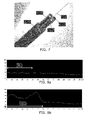
- Figs. 8a and 8b show graphs obtained with the LUNA G3 OSS system to monitor the axial strain on the launch region for two three rod embodiments of the invention.
- Axial strain on the launch region for a 205 micron coated optical fiber was measured.
- Fig. 13 shows a cross sectional sketch of another clamp mechanism embodiment.
- a body crossed area
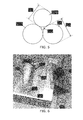
- a straight groove with an opening angle i.e. a V shaped groove.
- the straight groove is arranged to accommodate a section of the optical fiber OSF, and to fix the optical fiber OSF in a straight position in cooperation with a fixing element R1, here illustrated as a straight rod with circular cross section.
- a fixing element R1 here illustrated as a straight rod with circular cross section.
- the opening angle of the groove is 60°, it can be shown that the diameter of the rod should preferably be 3.0 times the diameter of the optical fiber OSF, in order to be able to fix the optical fiber OSF in the straight position without unnecessary strain.
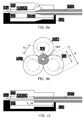
- Figs. 14-16 show illustrations of three different clamp mechanism embodiments where the fixing element comprises a spherical body cooperating with different types of additional fixing arrangements.
- the fixing element comprises a spherical body cooperating with different types of additional fixing arrangements.
- 3D line sketches are shown to the left, while 3D images of the same embodiments are shown to the right.
- the straight rod R1 could in principle be replaced by one or a plurality of spheres to serve as fixing elements instead of the rod R1.
Landscapes
- Physics & Mathematics (AREA)
- General Physics & Mathematics (AREA)
- Optics & Photonics (AREA)
- Health & Medical Sciences (AREA)
- Life Sciences & Earth Sciences (AREA)
- Surgery (AREA)
- Engineering & Computer Science (AREA)
- Veterinary Medicine (AREA)
- Robotics (AREA)
- Molecular Biology (AREA)
- Animal Behavior & Ethology (AREA)
- General Health & Medical Sciences (AREA)
- Public Health (AREA)
- Heart & Thoracic Surgery (AREA)
- Medical Informatics (AREA)
- Nuclear Medicine, Radiotherapy & Molecular Imaging (AREA)
- Biomedical Technology (AREA)
- Analytical Chemistry (AREA)
- Chemical & Material Sciences (AREA)
- Mechanical Coupling Of Light Guides (AREA)
- Light Guides In General And Applications Therefor (AREA)
- Length Measuring Devices By Optical Means (AREA)
Priority Applications (6)
| Application Number | Priority Date | Filing Date | Title |
|---|---|---|---|
| EP13187029.7A EP2857877A1 (en) | 2013-10-02 | 2013-10-02 | Clamp mechanism for clamping an optical shape sensing fiber |
| US15/025,403 US9593943B2 (en) | 2013-10-02 | 2014-09-30 | Clamp mechanism for clamping an optical shape sensing fiber |
| PCT/EP2014/070982 WO2015049256A1 (en) | 2013-10-02 | 2014-09-30 | Clamp mechanism for clamping an optical shape sensing fiber |
| JP2016517473A JP6200077B2 (ja) | 2013-10-02 | 2014-09-30 | 光学形状検知ファイバをクランプするクランプ機構 |
| CN201480054519.6A CN105593732B (zh) | 2013-10-02 | 2014-09-30 | 用于夹持光学形状感测纤维的夹持机构 |
| EP14777364.2A EP3052977B1 (en) | 2013-10-02 | 2014-09-30 | Clamp mechanism for clamping an optical shape sensing fiber |
Applications Claiming Priority (1)
| Application Number | Priority Date | Filing Date | Title |
|---|---|---|---|
| EP13187029.7A EP2857877A1 (en) | 2013-10-02 | 2013-10-02 | Clamp mechanism for clamping an optical shape sensing fiber |
Publications (1)
| Publication Number | Publication Date |
|---|---|
| EP2857877A1 true EP2857877A1 (en) | 2015-04-08 |
Family
ID=49293526
Family Applications (2)
| Application Number | Title | Priority Date | Filing Date |
|---|---|---|---|
| EP13187029.7A Withdrawn EP2857877A1 (en) | 2013-10-02 | 2013-10-02 | Clamp mechanism for clamping an optical shape sensing fiber |
| EP14777364.2A Active EP3052977B1 (en) | 2013-10-02 | 2014-09-30 | Clamp mechanism for clamping an optical shape sensing fiber |
Family Applications After (1)
| Application Number | Title | Priority Date | Filing Date |
|---|---|---|---|
| EP14777364.2A Active EP3052977B1 (en) | 2013-10-02 | 2014-09-30 | Clamp mechanism for clamping an optical shape sensing fiber |
Country Status (5)
| Country | Link |
|---|---|
| US (1) | US9593943B2 (enExample) |
| EP (2) | EP2857877A1 (enExample) |
| JP (1) | JP6200077B2 (enExample) |
| CN (1) | CN105593732B (enExample) |
| WO (1) | WO2015049256A1 (enExample) |
Cited By (1)
| Publication number | Priority date | Publication date | Assignee | Title |
|---|---|---|---|---|
| CN111405864A (zh) * | 2017-09-28 | 2020-07-10 | 皇家飞利浦有限公司 | 光学连接设备和方法 |
Families Citing this family (6)
| Publication number | Priority date | Publication date | Assignee | Title |
|---|---|---|---|---|
| EP3675721B1 (en) * | 2017-08-31 | 2022-04-20 | Koninklijke Philips N.V. | Sensing guidewire with integrated proximal locking feature |
| JP6483786B1 (ja) * | 2017-11-02 | 2019-03-13 | 株式会社フジクラ | 把持部材 |
| EP3518010A1 (en) * | 2018-01-30 | 2019-07-31 | Koninklijke Philips N.V. | Optical shape sensor, optical shape sensing console and system, and optical shape sensing method |
| CN109225757B (zh) * | 2018-10-15 | 2019-12-31 | 中南大学 | 一种磁吸装夹式光电探测器自动耦合点胶固化系统及方法 |
| CN110471146B (zh) * | 2019-08-29 | 2024-08-02 | 广州奥鑫通讯设备有限公司 | 一种光纤耦合器测试用工装结构件 |
| CN113108692A (zh) * | 2021-03-18 | 2021-07-13 | 众瑞速联(武汉)科技有限公司 | 一种用于二次元测试仪的mux组件测量装置及测量方法 |
Citations (4)
| Publication number | Priority date | Publication date | Assignee | Title |
|---|---|---|---|---|
| FR2282650A1 (fr) * | 1974-08-19 | 1976-03-19 | Corning Glass Works | Connecteur pour guides d'ondes optiques |
| US4201444A (en) * | 1976-04-26 | 1980-05-06 | International Telephone And Telegraph Corporation | Single optical fiber connector |
| FR2446496A1 (fr) * | 1977-11-24 | 1980-08-08 | Comp Generale Electricite | Fiche de connecteur fibre a fibre pour cable optique multifibre |
| EP0044953A1 (en) * | 1978-09-20 | 1982-02-03 | Nippon Telegraph And Telephone Corporation | Optical fiber alignment mechanism and connectors using the same |
Family Cites Families (9)
| Publication number | Priority date | Publication date | Assignee | Title |
|---|---|---|---|---|
| JPS5598711A (en) * | 1979-01-22 | 1980-07-28 | Nippon Telegr & Teleph Corp <Ntt> | Fabricating method of connector plug for optical fiber |
| JPS63148209A (ja) * | 1986-12-12 | 1988-06-21 | Sumitomo Electric Ind Ltd | 光コネクタ |
| JPH08262274A (ja) * | 1995-03-20 | 1996-10-11 | Japan Aviation Electron Ind Ltd | 光ファイバの整列構造 |
| WO2008131303A2 (en) | 2007-04-20 | 2008-10-30 | Hansen Medical, Inc. | Optical fiber shape sensing systems |
| US8347738B2 (en) | 2007-05-09 | 2013-01-08 | The Board Of Trustees Of The Leland Stanford Junior University | Sensors and control for an interventional catheter |
| US7815376B2 (en) | 2008-06-30 | 2010-10-19 | Intuitive Surgical Operations, Inc. | Fixture for shape-sensing optical fiber in a kinematic chain |
| CN102401939A (zh) | 2010-09-07 | 2012-04-04 | 西安金和光学科技有限公司 | 一种光纤对接装置 |
| KR101306935B1 (ko) | 2011-08-30 | 2013-09-10 | 주식회사 이제이텍 | 2열 광섬유센서를 이용한 터널의 형상 및 응력측정 방법 |
| CN102364362A (zh) * | 2011-11-01 | 2012-02-29 | 南京普天天纪楼宇智能有限公司 | 用于光纤冷接续子中的对接装置 |
-
2013
- 2013-10-02 EP EP13187029.7A patent/EP2857877A1/en not_active Withdrawn
-
2014
- 2014-09-30 JP JP2016517473A patent/JP6200077B2/ja active Active
- 2014-09-30 US US15/025,403 patent/US9593943B2/en active Active
- 2014-09-30 EP EP14777364.2A patent/EP3052977B1/en active Active
- 2014-09-30 WO PCT/EP2014/070982 patent/WO2015049256A1/en not_active Ceased
- 2014-09-30 CN CN201480054519.6A patent/CN105593732B/zh active Active
Patent Citations (4)
| Publication number | Priority date | Publication date | Assignee | Title |
|---|---|---|---|---|
| FR2282650A1 (fr) * | 1974-08-19 | 1976-03-19 | Corning Glass Works | Connecteur pour guides d'ondes optiques |
| US4201444A (en) * | 1976-04-26 | 1980-05-06 | International Telephone And Telegraph Corporation | Single optical fiber connector |
| FR2446496A1 (fr) * | 1977-11-24 | 1980-08-08 | Comp Generale Electricite | Fiche de connecteur fibre a fibre pour cable optique multifibre |
| EP0044953A1 (en) * | 1978-09-20 | 1982-02-03 | Nippon Telegraph And Telephone Corporation | Optical fiber alignment mechanism and connectors using the same |
Cited By (2)
| Publication number | Priority date | Publication date | Assignee | Title |
|---|---|---|---|---|
| CN111405864A (zh) * | 2017-09-28 | 2020-07-10 | 皇家飞利浦有限公司 | 光学连接设备和方法 |
| CN111405864B (zh) * | 2017-09-28 | 2023-08-29 | 皇家飞利浦有限公司 | 光学连接设备和方法 |
Also Published As
| Publication number | Publication date |
|---|---|
| WO2015049256A1 (en) | 2015-04-09 |
| EP3052977B1 (en) | 2017-08-02 |
| US20160231104A1 (en) | 2016-08-11 |
| CN105593732B (zh) | 2018-05-15 |
| JP6200077B2 (ja) | 2017-09-20 |
| EP3052977A1 (en) | 2016-08-10 |
| US9593943B2 (en) | 2017-03-14 |
| JP2016533478A (ja) | 2016-10-27 |
| CN105593732A (zh) | 2016-05-18 |
Similar Documents
| Publication | Publication Date | Title |
|---|---|---|
| US9593943B2 (en) | Clamp mechanism for clamping an optical shape sensing fiber | |
| US20190192124A1 (en) | Steerable Shape Sensing Biopsy Needle | |
| US9820632B2 (en) | Optical imaging probe having a handle with a cleaning mechanism | |
| JP7346393B2 (ja) | 光接続デバイスおよび方法 | |
| US11000265B1 (en) | Steerable biopsy needle with fiber-activated shape memory alloy | |
| US9987462B2 (en) | Elongated interventional device with variable stiffness | |
| US20180078317A1 (en) | Systems, methods and devices for tracking and calibration of flexible instruments | |
| US20150190123A1 (en) | Steerable Shape Sensing Biopsy Needle | |
| US6960028B2 (en) | Optical fiber connection utilizing fiber containing ferrules | |
| CN109974900B (zh) | 消融针固定装置及消融针热场检测实验设备 | |
| US9658406B2 (en) | Aligning a fiber in an optical fiber connector | |
| Ha et al. | Development of a multi-core fiber-Bragg-grating-based axial tip force sensor for left-atrial appendage closure procedure | |
| TW442676B (en) | Cylindrical optics assembly and method marking the same | |
| Carvalho et al. | Fabry-Perot cavity hydrostatic pressure sensors | |
| JP2005292540A (ja) | 光ファイバ用アダプタ | |
| JP6320232B2 (ja) | 出力測定装置用アダプタ | |
| US20210181431A1 (en) | Optical connecting component | |
| Issatayeva et al. | Fiber-optic based shape reconstruction of the medical needle for minimally invasive surgeries | |
| CN107484071B (zh) | 一种光纤拾音器及其制备方法和制备装置 | |
| Kumar et al. | Estimating needle-tissue interaction forces for hollow needles using fiber Bragg grating sensors | |
| Poeggel et al. | Low drift and high resolution miniature optical fiber combined pressure-and temperature sensor for cardio-vascular and urodynamic applications | |
| JPH0996733A (ja) | 光ファイバ接続器 | |
| Schneider et al. | Cantilevers orthodontics forces measured by fiber sensors | |
| US20110085765A1 (en) | Optical fiber coupler | |
| TW201503919A (zh) | 醫療機器 |
Legal Events
| Date | Code | Title | Description |
|---|---|---|---|
| PUAI | Public reference made under article 153(3) epc to a published international application that has entered the european phase |
Free format text: ORIGINAL CODE: 0009012 |
|
| 17P | Request for examination filed |
Effective date: 20131002 |
|
| AK | Designated contracting states |
Kind code of ref document: A1 Designated state(s): AL AT BE BG CH CY CZ DE DK EE ES FI FR GB GR HR HU IE IS IT LI LT LU LV MC MK MT NL NO PL PT RO RS SE SI SK SM TR |
|
| AX | Request for extension of the european patent |
Extension state: BA ME |
|
| STAA | Information on the status of an ep patent application or granted ep patent |
Free format text: STATUS: THE APPLICATION HAS BEEN WITHDRAWN |
|
| 18W | Application withdrawn |
Effective date: 20150507 |