EP2857834A2 - Ultrasonic pipe measurement apparatus - Google Patents
Ultrasonic pipe measurement apparatus Download PDFInfo
- Publication number
- EP2857834A2 EP2857834A2 EP14183922.5A EP14183922A EP2857834A2 EP 2857834 A2 EP2857834 A2 EP 2857834A2 EP 14183922 A EP14183922 A EP 14183922A EP 2857834 A2 EP2857834 A2 EP 2857834A2
- Authority
- EP
- European Patent Office
- Prior art keywords
- ultrasonic
- pipe
- damage
- measurement apparatus
- mode
- Prior art date
- Legal status (The legal status is an assumption and is not a legal conclusion. Google has not performed a legal analysis and makes no representation as to the accuracy of the status listed.)
- Granted
Links
Images




Classifications
-
- G—PHYSICS
- G01—MEASURING; TESTING
- G01N—INVESTIGATING OR ANALYSING MATERIALS BY DETERMINING THEIR CHEMICAL OR PHYSICAL PROPERTIES
- G01N29/00—Investigating or analysing materials by the use of ultrasonic, sonic or infrasonic waves; Visualisation of the interior of objects by transmitting ultrasonic or sonic waves through the object
- G01N29/04—Analysing solids
-
- G—PHYSICS
- G01—MEASURING; TESTING
- G01B—MEASURING LENGTH, THICKNESS OR SIMILAR LINEAR DIMENSIONS; MEASURING ANGLES; MEASURING AREAS; MEASURING IRREGULARITIES OF SURFACES OR CONTOURS
- G01B17/00—Measuring arrangements characterised by the use of infrasonic, sonic or ultrasonic vibrations
- G01B17/02—Measuring arrangements characterised by the use of infrasonic, sonic or ultrasonic vibrations for measuring thickness
-
- G—PHYSICS
- G01—MEASURING; TESTING
- G01N—INVESTIGATING OR ANALYSING MATERIALS BY DETERMINING THEIR CHEMICAL OR PHYSICAL PROPERTIES
- G01N17/00—Investigating resistance of materials to the weather, to corrosion, or to light
-
- G—PHYSICS
- G01—MEASURING; TESTING
- G01N—INVESTIGATING OR ANALYSING MATERIALS BY DETERMINING THEIR CHEMICAL OR PHYSICAL PROPERTIES
- G01N29/00—Investigating or analysing materials by the use of ultrasonic, sonic or infrasonic waves; Visualisation of the interior of objects by transmitting ultrasonic or sonic waves through the object
- G01N29/04—Analysing solids
- G01N29/043—Analysing solids in the interior, e.g. by shear waves
-
- G—PHYSICS
- G01—MEASURING; TESTING
- G01N—INVESTIGATING OR ANALYSING MATERIALS BY DETERMINING THEIR CHEMICAL OR PHYSICAL PROPERTIES
- G01N29/00—Investigating or analysing materials by the use of ultrasonic, sonic or infrasonic waves; Visualisation of the interior of objects by transmitting ultrasonic or sonic waves through the object
- G01N29/04—Analysing solids
- G01N29/07—Analysing solids by measuring propagation velocity or propagation time of acoustic waves
-
- G—PHYSICS
- G01—MEASURING; TESTING
- G01N—INVESTIGATING OR ANALYSING MATERIALS BY DETERMINING THEIR CHEMICAL OR PHYSICAL PROPERTIES
- G01N29/00—Investigating or analysing materials by the use of ultrasonic, sonic or infrasonic waves; Visualisation of the interior of objects by transmitting ultrasonic or sonic waves through the object
- G01N29/04—Analysing solids
- G01N29/11—Analysing solids by measuring attenuation of acoustic waves
-
- G—PHYSICS
- G01—MEASURING; TESTING
- G01N—INVESTIGATING OR ANALYSING MATERIALS BY DETERMINING THEIR CHEMICAL OR PHYSICAL PROPERTIES
- G01N2291/00—Indexing codes associated with group G01N29/00
- G01N2291/01—Indexing codes associated with the measuring variable
- G01N2291/015—Attenuation, scattering
-
- G—PHYSICS
- G01—MEASURING; TESTING
- G01N—INVESTIGATING OR ANALYSING MATERIALS BY DETERMINING THEIR CHEMICAL OR PHYSICAL PROPERTIES
- G01N2291/00—Indexing codes associated with group G01N29/00
- G01N2291/02—Indexing codes associated with the analysed material
- G01N2291/023—Solids
-
- G—PHYSICS
- G01—MEASURING; TESTING
- G01N—INVESTIGATING OR ANALYSING MATERIALS BY DETERMINING THEIR CHEMICAL OR PHYSICAL PROPERTIES
- G01N2291/00—Indexing codes associated with group G01N29/00
- G01N2291/02—Indexing codes associated with the analysed material
- G01N2291/028—Material parameters
- G01N2291/02854—Length, thickness
-
- G—PHYSICS
- G01—MEASURING; TESTING
- G01N—INVESTIGATING OR ANALYSING MATERIALS BY DETERMINING THEIR CHEMICAL OR PHYSICAL PROPERTIES
- G01N2291/00—Indexing codes associated with group G01N29/00
- G01N2291/02—Indexing codes associated with the analysed material
- G01N2291/028—Material parameters
- G01N2291/0289—Internal structure, e.g. defects, grain size, texture
-
- G—PHYSICS
- G01—MEASURING; TESTING
- G01N—INVESTIGATING OR ANALYSING MATERIALS BY DETERMINING THEIR CHEMICAL OR PHYSICAL PROPERTIES
- G01N2291/00—Indexing codes associated with group G01N29/00
- G01N2291/26—Scanned objects
- G01N2291/263—Surfaces
- G01N2291/2634—Surfaces cylindrical from outside
Definitions
- the present disclosure relates to an ultrasonic pipe measurement apparatus.
- An ultrasonic pipe measurement apparatus is an apparatus employs an ultrasonic wave to measure a generation point and size or amount of such as the damage occurred by corrosion or erosion in the pipe and scale attached to the inside of the pipe (that is, the conditions of a pipe).
- an ultrasonic thickness meter As an apparatus for detecting and measuring corrosion and erosion in a pipe, an ultrasonic thickness meter has been known. The ultrasonic thickness meter measures the wall thickness of a pipe using the propagation time of ultrasonic waves to measure the thickness loss due to corrosion or erosion.
- FIG. 8 is a diagram illustrating an exemplary structure of the ultrasonic thickness meter ( JP-A-2000-329751 ). As illustrated in FIG. 8 , this ultrasonic thickness meter includes a piezoelectric ultrasonic transducer 1, an ultrasonic transceiver 2, a signal processing device 3, and an ultrasonic waveform display device 4 such as an oscilloscope.
- the signal processing device 3 performs, for example, the calculation of the attenuation rate of the ultrasonic multiple echoes, the calculation of the amplification ratio between the incident ultrasonic echo and the reflection ultrasonic echo, and the signal processing for improving the SN ratio of a multiple reflection echo signal.
- the pipe to be inspected has a pipe main body 5 made of iron or stainless steel.
- the inner surface of the pipe main body 5 is provided with a plastic or rubber lining 6.
- a fluid (couplant) 10 suppresses the reflection of the ultrasonic wave on the surface of the pipe main body 5.
- an ultrasonic echo 7 is introduced into the pipe main body 5 through the outer surface thereof to detect an ultrasonic echo 8 from the lining 6 and the inner surface of the pipe main body 5.
- an ultrasonic echo 8 is introduced into the pipe main body 5 through the outer surface thereof to detect an ultrasonic echo 8 from the lining 6 and the inner surface of the pipe main body 5.
- FIG. 9 is a diagram illustrating an exemplary structure of an apparatus for detecting the corrosion and erosion of the pipe by using a guide wave ( JP-A-2005-10055 ).
- a guide wave transceiver 11 is a device that generates a guide wave 18 in a pipe 19 and includes, for example, a piezoelectric element.
- the guide wave transceiver 11 is disposed in contact with the pipe 19, and is electrically connected to a guide wave transceiver unit 13 through a coaxial cable.
- a transceiver ring 12 is a jig for annularly holding a plurality of guide wave transceivers 11 around the pipe.
- the transceiver ring 12 preferably includes a structure configured to house the guide wave transceivers 11 at equal intervals in a circumferential direction and a structure detachable from the pipe.
- the transceiver ring 12 has a ring-shaped frame with a structure that can be divided into two. In other words, the ring-shaped frame can be assembled by cutting a ring-shaped component into two divided pieces along the diameter of the ring and connecting the ends of the respective divided pieces together using a screw. Thus, as the divided pieces are connected together to surround the outer periphery of the pipe 19, the transceiver ring 12 can be attached around the outer periphery of the pipe 19.
- the plurality of guide wave transceivers 11 are housed on the inside of the ring-shaped frame of the transceiver ring 12. Moreover, the inside of the ring-shaped frame is supported by a spring that extends or contracts relative to the outer peripheral surface of the pipe 19. Therefore, upon the attachment of the transceiver ring 12 to the outer peripheral surface of the pipe 19, the spring presses the plurality of guide wave transceivers 11 are against the outer peripheral surface of the pipe 19. Thus, the guide wave transceivers 11 can easily generate the guide wave 18 to the pipe 19.
- the guide wave transceiver unit 13 applies a transmission waveform to the guide wave transceiver 11 to transmit the guide wave 18. Moreover, the guide wave transceiver unit 13 amplifies the reception waveform from the guide wave transceiver 11.
- the guide wave transceiver unit 13 is connected to a waveform generation/analysis unit 15 to enable the communication of digital data.
- the guide wave transceiver unit 13 is connected to an A/D converter 14 through the coaxial cable for transmitting a reception waveform to the A/D converter 14.
- the A/D converter 14 has a function to convert an analogue signal into a digital signal.
- the A/D converter 14 is connected to the guide wave transceiver unit 13 and the waveform generation/analysis unit 15.
- the A/D converter 14 is able to convert the reception waveform of the guide wave 18 output from the guide wave transceiver unit 13 into the digital waveform to communicate with the waveform generation/analysis unit 15.
- the waveform generation/analysis unit 15 generates the transmission waveform and analyzes the reception waveform, while controlling the entire operation of a pipe inspection apparatus.
- the waveform generation/analysis unit 15 includes a computer or the like.
- the waveform generation/analysis unit 15 is connected to an input unit 16 such as a keyboard that accepts the instruction from a user, and to a display unit 17 such as a CRT.
- the thickness, the material, and the sound velocity of the pipe, a region R to be inspected, and the reference waveform are input to the waveform generation/analysis unit 15.
- the waveform of the reception wave (reception waveform) when the guide wave according to the reference waveform is reflected on a defect Do at the center of the region R to be inspected and is received at the guide wave transceiver 11 is calculated based on the thickness and the material. Transmission waveforms are generated so that the calculated reception waveforms can be transmitted in order from the late reception time.
- the guide wave transceiver unit 13 applies a signal based on the transmission waveform to the guide wave transceiver 11 to generate the guide wave 18.
- the guide wave transceiver unit 13 receives the reception waveform of the guide wave 18 from the guide wave transceiver 11.
- the A/D converter 14 converts the signal into a digital signal.
- the waveform generation/analysis unit 15 displays the digital signal on the display unit 17 as an inspection result.
- the pipe corrosion can be roughly divided into two types.
- One is called general corrosion, in which the inside of the pipe is uniformly corroded due to the flowing fluid and the wall of a pipe (hereinafter, also referred to as a pipe wall) is reduced in thickness uniformly. This corrosion often appears in a carbon steel pipe or the like.
- an ultrasonic thickness meter is set at any point on the tube. The appropriate countermeasure can be taken by recognizing the thickness measured with the ultrasonic thickness meter as the thickness of the entire pipe wall.
- the other type of the pipe corrosion is called localized corrosion in which the thickness reduction (pitting) or damage progresses locally.
- the corrosion often appears in a stainless steel pipe or the like.
- the localized corrosion can be detected when the corrosion has occurred in the place where the ultrasonic thickness meter is set. However, it is impossible to detect the localized corrosion that has occurred in a generation place different from the place where the ultrasonic thickness meter is set.
- An ultrasonic pipe measurement apparatus includes: a plurality of ultrasonic transceivers discretely disposed on a pipe wall of a pipe; and a control unit configured to control the plurality of ultrasonic transceivers and detect a generation point of damage caused in the pipe based on an ultrasonic signal exchanged between the ultrasonic transceivers.
- the major problem of localized corrosion in a pipe is that the generation point thereof cannot be predicted.
- the pipe may be covered with ultrasonic thickness meters. This method, however, is not practical from the economical point of view.
- the use of a guide wave enables the detection of a damage due to localized corrosion at a relatively far point in the pipe.
- the wall thickness of the pipe serves as a limiting factor.
- it is difficult to measure the size of corrosion for example, the diameter of a pitting, which is one kind of localized corrosion. In the case where the size of the localized corrosion cannot be detected, it is difficult to take an appropriate countermeasure.
- One of the objects of the present disclosure is to provide an ultrasonic pipe measurement apparatus that can detect localized corrosion and scale attached to the inside of the pipe, measure the generation point and the size or amount of each of them, and take an appropriate countermeasure as necessary without covering the pipe with the ultrasonic transceivers.
- An ultrasonic pipe measurement apparatus includes: a plurality of ultrasonic transceivers discretely disposed on a pipe wall of a pipe; and a control unit configured to control the plurality of ultrasonic transceivers and detect a generation point of damage caused in the pipe based on an ultrasonic signal exchanged between the ultrasonic transceivers.
- the number of ultrasonic transceivers may be three or more.
- the control unit may be configured to detect a generation point of the damage caused in the pipe based on time after the ultrasonic wave is output from one ultrasonic transceiver and before a reflection wave from the damage is received by each ultrasonic transceiver.
- the control unit may be configured to measure a size of the damage caused in the pipe based on the ultrasonic signal exchanged between the ultrasonic transceivers.
- the control unit may be configured to measure the size of the damage caused in the pipe based on an amplitude of the reflection wave from the damage received by the ultrasonic transceiver.
- the control unit may have operation modes including a search mode wherein an interval of transmitting an ultrasonic pulse is set relatively long, the search mode being, the search mode being adapted to detect a point of the damage and the approximate size of the damage, and a measurement mode adapted to accurately measure the size of the damage, the measurement mode allowing an ultrasonic pulse with an amplitude and a transmission interval sufficient for required accuracy to be transmitted; and the control unit may be configured to maintain the operation mode to be the search mode when the size of the damage measured in the search mode is less than or equal to a predetermined threshold.
- the control unit may be configured to switch the operation mode from the search mode to the measurement mode when the size of the damage measured in the search mode is greater than the predetermined threshold.
- the control unit may be configured to switch the operation mode from the measurement mode to the search mode when the size of the damage measured in the measurement mode is less than or equal to the predetermined threshold.
- the control unit may be configured to execute both the search mode and the measurement mode when a plurality of damages with different sizes is detected.
- the control unit may be configured to sequentially switch the ultrasonic transceivers that transmit the ultrasonic waves.
- the plurality of ultrasonic transceivers may be configured to transmit the ultrasonic waves with different frequencies.
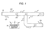
- FIG. 1 is a block diagram illustrating an embodiment of the present disclosure.
- a plurality of ultrasonic transceivers US1 to USn is attached to an outer wall of a pipe 20 discretely in the direction of the pipe 20.
- the number of ultrasonic transceivers US1 to USn may be three or more.
- the outer diameter of the pipe 20 is set to approximately 100 mm
- the distance between the adjacent ultrasonic transceivers is set to approximately 1000 mm
- the frequency of the ultrasonic wave is set to approximately 50 kHz to 5 MHz.
- the ultrasonic transceivers US1 to USn are connected to a measurement apparatus main body (control unit) 30 in a wired or wireless manner, and transmit and receive ultrasonic signals to and from the pipe 20 according to the control from the measurement apparatus main body 30.
- the ultrasonic transceivers US1 to USn are disposed evenly throughout the pipe 20 in some cases while the ultrasonic transceivers US1 to USn are concentrated on important points in other cases.
- the ultrasonic transceivers US1 to USn are not operated individually. Two or more of them can be operated in cooperation.
- the measurement apparatus main body 30 has functions of generation, calculation, and the like with respect to an ultrasonic signal transmitted and output to the ultrasonic transceivers US1 to US2.
- the calculation function is a function of subjecting reception signals from at least three of the ultrasonic transceiver US1 to USn to arithmetic processing to determine the point, outer diameter, depth (thickness of pipe wall), and the like of the damage of the pipe 20 caused by the corrosion or erosion.
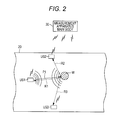
- FIG. 2 is a diagram illustrating the operation for detecting the point of damage W of the pipe 20 caused by the corrosion or erosion.
- an ultrasonic pulse is output from the ultrasonic transceiver US1.
- the output ultrasonic pulse (ultrasonic signal) propagates along the pipe wall of the pipe 20 and reaches the damage W caused by the corrosion or erosion.
- the measurement apparatus main body 30 calculates the point of the damage W based on the propagation time T1 to T3 of the reflection waves R1 to R3 from the damage W by, for example, the triangulation method. Note that the reflection wave is not generated when the damage is not present in the measurement region.
- the propagation time T1 to T3 of the reflection waves R1 to R3 refers to the time required from when the ultrasonic pulse is output (transmitted) from the ultrasonic transceiver US1 to when the reflection waves R1 to R3 from the damage W are received by the ultrasonic transceivers US1 to US3.
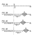
- FIGS. 3A to 3C are diagrams illustrating examples of the waveforms in each portion in the structure of FIG. 2 .
- FIG. 3A illustrates the driving waveform of the ultrasonic transceiver US1.
- FIG. 3B illustrates the waveform of the reflection wave R1 received by the ultrasonic transceiver US1.
- FIG. 3C illustrates the reception waveform of the reflection wave R2 received by the ultrasonic transceiver US2.
- FIG. 3D illustrates the reception waveform of the reflection wave R3 received by the ultrasonic transceiver US3.
- the operation mode with a main purpose of detecting the point of the damage W caused by the corrosion or the erosion is referred to as a search mode.
- this search mode the corrosion velocity predicted from the nature and flow rate of the fluid and the material of the pipe is taken into consideration.
- the intervals of transmitting the ultrasonic pulses are set relatively long from the viewpoint of lower energy consumption (for example, once a day or once in several days or weeks).
- the measurement apparatus main body 30 identifies the point of the damage at the transmission intervals. Then, the measurement apparatus main body 30 obtains the rough values of the outer diameter and depth of the detected damage.
- the search mode is the operation mode wherein the interval of transmitting the ultrasonic is set relatively long, the search mode being adapted to detect the point of the damage and the approximate size of the damage.
- FIG. 4 is a diagram illustrating the operation for measuring the outer diameter of the damage W of the pipe 20 caused by the corrosion or erosion.
- the measurement apparatus main body 30 measures the end face around the damage by using the ultrasonic signals output from the ultrasonic transceivers including US2 and US3, which are the transceivers other than the transceiver US1.
- FIG. 5 is a diagram illustrating the operation for measuring the depth of the damage W of the pipe 20 caused by the corrosion or erosion.
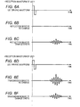
- FIGS. 6A to 6F are diagrams illustrating examples of the waveforms in each portion in the structure of FIG. 5 .
- FIG. 6A and FIG. 6D illustrate the driving waveform of the ultrasonic transceiver US1.
- FIG. 6B and FIG. 6C illustrate the reception waveform of the ultrasonic transceiver US1.
- FIG. 6E and FIG. 6F illustrate the reception waveform of the ultrasonic transceiver US2.
- the amplitude of the reception waveform in the ultrasonic transceiver US1 does not appear as illustrated in FIG. 6B .
- the reflection wave R1 is generated. Therefore, the amplitude of the reception waveform in the ultrasonic transceiver US1 appears as illustrated in FIG. 6C .
- the magnitude of the amplitude depends on the depth of the damage W.
- the measurement apparatus main body 30 can measure the size of the damage W in the pipe 20 based on the amplitudes of the reflection waves from the damage W that are received by the ultrasonic transceivers US1 to USn.
- the ultrasonic transceiver US2 substantially directly receives the transmission wave PI of the ultrasonic transceiver US1 as illustrated in FIG. 6E .
- the amplitude of the reception waveform of the ultrasonic transceiver US2 becomes sufficiently large.
- the amplitude of the reception waveform of the ultrasonic transceiver US2 is reduced depending on the depth of the damage W as illustrated in FIG. 6F .
- the measurement apparatus main body 30 can measure the depth of the damage W based on the magnitude of the amplitude of the reception waveform in the ultrasonic transceiver US1 and/or US2. Specifically, when the size of the damage W detected in the search mode is less than or equal to a predetermined threshold, the measurement apparatus main body 30 sets the operation mode to the search mode (maintains the search mode). On the other hand, when the size of the damage W detected in the search mode is greater than the predetermined threshold, the measurement apparatus main body 30 transits the operation mode from the search mode to the measurement mode.
- the measurement apparatus main body 30 controls the plurality of ultrasonic transceivers provided around the damage W so as to transmit the ultrasonic pulses with the amplitudes and transmission intervals enough for the required accuracy.
- the measurement mode is the operation mode adapted to accurately measure the size of the damage, in which the ultrasonic pulses with the amplitudes and transmission intervals enough for the required accuracy are transmitted.
- the measurement apparatus main body 30 In the measurement mode, the measurement apparatus main body 30 accurately measures the size of the damage W that is greater than the predetermined threshold. Moreover, the measurement apparatus main body 30 accurately measures the change in size of the damage W over time, i.e., the progressing velocity of the damage W. For increasing the accuracy, the ultrasonic transceivers US1 to USn apply the pulse signals with higher energy in this measurement mode than in the search mode.
- the amplitude may be increased and the number of pulses may be increased to form burst waves, for example.
- the measurement method is basically the same as the method in the search mode.
- the fast-progressing damage W can be dealt with.
- these can be used as the indicator for the next action of a user.
- the next action corresponds to, for example, the exchange of pipes and the injection of an anticorrosive.
- the outer diameter of the damage W measured roughly in the search mode is measured with high accuracy in the measurement mode.
- the diameter of the damage W may be less than or equal to the threshold.
- the measurement apparatus main body 30 may set the operation mode back to the search mode from the measurement mode. In other words, in this case, the measurement apparatus main body 30 may switch the operation mode from the measurement mode to the search mode.
- the measurement apparatus main body 30 switches the ultrasonic transceivers US1 to USn in order and operates the transceivers as the transmitters.
- the measurement apparatus main body 30 causes the ultrasonic transceivers US1 to USn to transmit the ultrasonic signals in order while deviating the transmission timing.
- the amount of time deviation is set to, for example, the amount enough to avoid the interference.
- the measurement apparatus main body 30 manages the amount of time deviation.
- the frequency of the pulse transmitted may be changed for every one of the ultrasonic transceivers US1 to USn.
- the ultrasonic transceivers US1 to USn may be configured to transmit the ultrasonic pulses with different frequencies.
- the reception side distinguishes between the ultrasonic signals from the ultrasonic transceivers US1 to USn (transmitters) through a band pass filter or the like.
- the measurement apparatus main body 30 also manages the selection of the transmission frequency and the band pass filter. According to this method, the plurality of ultrasonic transceivers can transmit the ultrasonic signals at the same time.
- the measurement apparatus main body 30 may execute both the search mode and the measurement mode when it has been determined that a plurality of damages with different sizes exists in the search mode or the measurement mode (when the plurality of damages with different sizes have been detected).
- the measurement apparatus main body 30 may operate the ultrasonic transceivers US1 to USn in the measurement mode relative to the damage with the size greater than the threshold.
- the measurement apparatus main body 30 may operate the ultrasonic transceivers US1 to USn in the search mode relative to the other damages.
- the search mode and the measurement mode coexist in the entire ultrasonic pipe measurement apparatus.
- the damage can be detected by the coexistence of the search mode and the measurement mode.
- a method of the coexistence for example, there are a method of repeating the search mode and the measurement mode by time division and a method of identifying the point of the damage while the measurement mode is maintained.
- the measurement apparatus main body 30 is set so that, for example, the detection of the damage and the measurement of the point of the damage are possible even in the measurement mode.
- FIG. 7 is a flowchart of the operation of the apparatus.
- the measurement apparatus main body 30 detects the presence or absence of, and the point of the damage caused by the corrosion or erosion in the pipe 20 (Step S1). Subsequently, the measurement apparatus main body 30 measures the size of the damage (Step S2). The measurement apparatus main body 30 determines whether the measured size of the damage is greater than a predetermined threshold (Step S3). The aforementioned operation steps are in the search mode.
- the measurement apparatus main body 30 transits the operation mode from the search mode to the measurement mode.
- the measurement apparatus main body 30 adjusts the measurement time intervals (Step S4) and measures the size of the damage with high accuracy (Step S5).
- the measurement apparatus main body 30 determines whether the accurate measurement result on the size of the damage is greater than a predetermined threshold (Step S6).
- the measurement apparatus main body 30 calculates the damage growth velocity (Step S7) by dividing the change in size of the damage by the measurement time intervals, and displays the calculation result (Step S8). Note that the measurement apparatus main body 30 repeats the process from Step S4 to Step S8 in the measurement mode while adjusting the measurement time intervals as appropriate.
- the measurement apparatus main body 30 returns to Step S1 and repeats the process from the search mode to the measurement mode.
- the signal parameter used in the detection of the damage is not limited to the propagation time and the amplitude.
- the measurement apparatus main body 30 can obtain various pieces of information by focusing on other signal parameters (using other signal parameters).
- the measurement apparatus main body 30 may use, for example, the frequency spectrum.
- the frequency spectrum of the reception wave includes the clear peak at the frequency according to the pipe wall thickness. Therefore, by observing the frequency spectrum of the reception signal, the measurement apparatus main body 30 can measure the state of the damage in the pipe and the pipe wall thickness (detect the general corrosion and detect the localized corrosion such as pitting right under the ultrasonic transceivers US1 to USn).
- the measurement apparatus main body 30 can measure the size of the damage more accurately by using the phase shift amount when the frequency spectrum is used.
- the measurement apparatus main body 30 may use the cepstrum used in the audio signal processing, etc. Through the cepstrum analysis of the signal distortion due to the damage, the measurement apparatus main body 30 can extract the distortion of the signal, i.e., the feature data of the damage (such as the size). Thus, the measurement apparatus main body 30 can perform various signal processes on the signals from the plurality of ultrasonic transceivers US1 to USn disposed in the pipe. This enables the measurement apparatus main body 30 to detect the generation point of the damage and measure the size of the damage.
- the above embodiment has described the ultrasonic transceivers US1 to USn as a single device.
- the directions where the ultrasonic waves are transmitted from the ultrasonic transceivers US1 to USn can be controlled arbitrarily.
- the measurement apparatus main body 30 may drive the ultrasonic transceivers US1 to USn at the same time by applying the phase difference to the ultrasonic waves transmitted from the ultrasonic transceivers US1 to USn. This enables the ultrasonic transceivers US1 to USn to operate similar to the phased array as a whole.
- the measurement apparatus main body 30 detects the generation point of the damage caused by the corrosion or erosion in the pipe and measures the size of the damage.
- the measurement apparatus main body 30 can similarly detect and measure the scale attached to the inner wall of the pipe.
- the ultrasonic pipe measurement apparatus that can achieve the following can be provided: the measurement of the state of the pipe including the generation point and the size of the damage in the pipe caused by the corrosion or erosion and the scale attached to the inside of the pipe without covering the pipe with the ultrasonic transceivers; and the necessary appropriate countermeasure.
- the measurement apparatus main body 30 may set the operation mode to the measurement mode when the detected size of the damage W is greater than a predetermined threshold and set the operation mode to the search mode when the detected size of the damage W is less than or equal to the predetermined threshold.
- the localized corrosion can be detected without covering the pipe with the ultrasonic transceivers, whereby the generation point and the size of the corrosion and the scale attached to the inside of the pipe can be measured and the appropriate countermeasure can be taken as necessary.
- the interval of transmitting the ultrasonic pulses is set relatively long, for example, once a day or once in several days or weeks to identify the generation point of the damage. Then, in regard to the detected outer diameter and depth of the damage, the rough values may be measured.
- FIGS. 6A to 6F attention is paid to the reception waveform of the ultrasonic transceiver US1.
- the reflection wave R1 is not generated; thus, the amplitude of the reception waveform is not observed as illustrated in FIG. 6B .
- the reflection wave R1 is generated as illustrated in FIG. 6C and the magnitude of the amplitude depends on the depth of the damage W.
- the amplitude is large because the transmission wave P1 of the ultrasonic transceiver US1 is received substantially directly as illustrated in FIG. 6B .
- the amplitude of the reception waveform is attenuated depending on the depth of the damage W as illustrated in FIG. 6C .
- the operation similar to that of the ultrasonic transceiver US1 may be applied to the ultrasonic transceivers in the order of US2 ⁇ US3 ⁇ ... so that the ultrasonic transceivers operate as the transmitter.
- the ultrasonic transceivers may transmit the signals in order while deviating the timing in order to distinguish the ultrasonic signals transmitted from the ultrasonic transceivers.
- the amount of time deviation may be set to the amount enough to avoid the interference.
- the entire ultrasonic pipe measurement apparatus may allow the coexistence of the search mode and the measurement mode by conducting the measurement mode for the damages with the size greater than the threshold and the search mode for the other damages. Even in the occurrence of another damage in the pipe 20 during the operation in the measurement mode, the damage can be detected by the coexistence of the search mode and the measurement mode.
- a method of the coexistence for example, there are a method of repeating the search mode and the measurement mode by time division and a method of identifying the point of the damage while the measurement mode is maintained.
- the detection of the damage and the measurement of the point may be enabled in the measurement mode.
- the direction where the ultrasonic wave is transmitted may be controlled arbitrarily by the use of the phased array.
- the ultrasonic pipe measurement apparatus may be any of the following first to fourth ultrasonic pipe measurement apparatus.
- a first ultrasonic pipe measurement apparatus is an ultrasonic pipe measurement apparatus that measures a state of a pipe by using an ultrasonic wave, wherein: at least three ultrasonic transceivers are provided discretely on a pipe wall of the pipe; and the generation point of damage caused in the pipe and the size thereof are measured based on an ultrasonic signal exchanged between the ultrasonic transceivers.
- a second ultrasonic pipe measurement apparatus is the first ultrasonic pipe measurement apparatus wherein: the operation mode includes a search mode and a measurement mode; the search mode is employed when the size of the damage is less than a predetermined threshold; the measurement mode is employed when the size of the damage is greater than the predetermined threshold; and the two modes coexist when a plurality of damages with different sizes exists.
- a third ultrasonic pipe measurement apparatus is the second ultrasonic pipe measurement apparatus wherein: the operation mode is switched from the search mode to the measurement mode when the size of the damage from low-accurate measurement in the search mode has exceeded the predetermined threshold.
- a fourth ultrasonic pipe measurement apparatus is the second or third ultrasonic pipe measurement apparatus wherein: in the search mode, the point of the damage is detected while suppressing the output by setting the interval of transmitting ultrasonic pulses relatively long; and in the measurement mode, the ultrasonic pulses with an amplitude and transmission interval sufficient for required accuracy is transmitted.
Landscapes
- Physics & Mathematics (AREA)
- Life Sciences & Earth Sciences (AREA)
- General Physics & Mathematics (AREA)
- Chemical & Material Sciences (AREA)
- Pathology (AREA)
- Analytical Chemistry (AREA)
- Biochemistry (AREA)
- General Health & Medical Sciences (AREA)
- Health & Medical Sciences (AREA)
- Immunology (AREA)
- Acoustics & Sound (AREA)
- Biodiversity & Conservation Biology (AREA)
- Ecology (AREA)
- Environmental & Geological Engineering (AREA)
- Environmental Sciences (AREA)
- Investigating Or Analyzing Materials By The Use Of Ultrasonic Waves (AREA)
- Length Measuring Devices Characterised By Use Of Acoustic Means (AREA)
Abstract
Description
- This application claims priority from Japanese Patent Application No.
2013-189360 - The present disclosure relates to an ultrasonic pipe measurement apparatus.
- An ultrasonic pipe measurement apparatus is an apparatus employs an ultrasonic wave to measure a generation point and size or amount of such as the damage occurred by corrosion or erosion in the pipe and scale attached to the inside of the pipe (that is, the conditions of a pipe). As an apparatus for detecting and measuring corrosion and erosion in a pipe, an ultrasonic thickness meter has been known. The ultrasonic thickness meter measures the wall thickness of a pipe using the propagation time of ultrasonic waves to measure the thickness loss due to corrosion or erosion.
-
FIG. 8 is a diagram illustrating an exemplary structure of the ultrasonic thickness meter (JP-A-2000-329751 FIG. 8 , this ultrasonic thickness meter includes a piezoelectric ultrasonic transducer 1, anultrasonic transceiver 2, asignal processing device 3, and an ultrasonicwaveform display device 4 such as an oscilloscope. - The
signal processing device 3 performs, for example, the calculation of the attenuation rate of the ultrasonic multiple echoes, the calculation of the amplification ratio between the incident ultrasonic echo and the reflection ultrasonic echo, and the signal processing for improving the SN ratio of a multiple reflection echo signal. Note that the pipe to be inspected has a pipemain body 5 made of iron or stainless steel. The inner surface of the pipemain body 5 is provided with a plastic orrubber lining 6. A fluid (couplant) 10 suppresses the reflection of the ultrasonic wave on the surface of the pipemain body 5. - In such a structure, an
ultrasonic echo 7 is introduced into the pipemain body 5 through the outer surface thereof to detect anultrasonic echo 8 from thelining 6 and the inner surface of the pipemain body 5. Thus, the separation between the pipemain body 5 and thelining 6 can be detected. -
FIG. 9 is a diagram illustrating an exemplary structure of an apparatus for detecting the corrosion and erosion of the pipe by using a guide wave (JP-A-2005-10055 FIG. 9 , aguide wave transceiver 11 is a device that generates aguide wave 18 in apipe 19 and includes, for example, a piezoelectric element. Theguide wave transceiver 11 is disposed in contact with thepipe 19, and is electrically connected to a guidewave transceiver unit 13 through a coaxial cable. - A
transceiver ring 12 is a jig for annularly holding a plurality ofguide wave transceivers 11 around the pipe. Thetransceiver ring 12 preferably includes a structure configured to house theguide wave transceivers 11 at equal intervals in a circumferential direction and a structure detachable from the pipe. Thetransceiver ring 12 has a ring-shaped frame with a structure that can be divided into two. In other words, the ring-shaped frame can be assembled by cutting a ring-shaped component into two divided pieces along the diameter of the ring and connecting the ends of the respective divided pieces together using a screw. Thus, as the divided pieces are connected together to surround the outer periphery of thepipe 19, thetransceiver ring 12 can be attached around the outer periphery of thepipe 19. - On the inside of the ring-shaped frame of the
transceiver ring 12, the plurality ofguide wave transceivers 11 are housed. Moreover, the inside of the ring-shaped frame is supported by a spring that extends or contracts relative to the outer peripheral surface of thepipe 19. Therefore, upon the attachment of thetransceiver ring 12 to the outer peripheral surface of thepipe 19, the spring presses the plurality ofguide wave transceivers 11 are against the outer peripheral surface of thepipe 19. Thus, theguide wave transceivers 11 can easily generate theguide wave 18 to thepipe 19. - The guide
wave transceiver unit 13 applies a transmission waveform to theguide wave transceiver 11 to transmit theguide wave 18. Moreover, the guidewave transceiver unit 13 amplifies the reception waveform from theguide wave transceiver 11. The guidewave transceiver unit 13 is connected to a waveform generation/analysis unit 15 to enable the communication of digital data. The guidewave transceiver unit 13 is connected to an A/D converter 14 through the coaxial cable for transmitting a reception waveform to the A/D converter 14. - The A/
D converter 14 has a function to convert an analogue signal into a digital signal. The A/D converter 14 is connected to the guidewave transceiver unit 13 and the waveform generation/analysis unit 15. Thus, the A/D converter 14 is able to convert the reception waveform of theguide wave 18 output from the guidewave transceiver unit 13 into the digital waveform to communicate with the waveform generation/analysis unit 15. - The waveform generation/
analysis unit 15 generates the transmission waveform and analyzes the reception waveform, while controlling the entire operation of a pipe inspection apparatus. The waveform generation/analysis unit 15 includes a computer or the like. The waveform generation/analysis unit 15 is connected to aninput unit 16 such as a keyboard that accepts the instruction from a user, and to adisplay unit 17 such as a CRT. - In such a structure, the thickness, the material, and the sound velocity of the pipe, a region R to be inspected, and the reference waveform are input to the waveform generation/
analysis unit 15. The waveform of the reception wave (reception waveform) when the guide wave according to the reference waveform is reflected on a defect Do at the center of the region R to be inspected and is received at theguide wave transceiver 11 is calculated based on the thickness and the material. Transmission waveforms are generated so that the calculated reception waveforms can be transmitted in order from the late reception time. - The guide
wave transceiver unit 13 applies a signal based on the transmission waveform to theguide wave transceiver 11 to generate theguide wave 18. The guidewave transceiver unit 13 receives the reception waveform of theguide wave 18 from theguide wave transceiver 11. The A/D converter 14 converts the signal into a digital signal. The waveform generation/analysis unit 15 displays the digital signal on thedisplay unit 17 as an inspection result. - The pipe corrosion can be roughly divided into two types. One is called general corrosion, in which the inside of the pipe is uniformly corroded due to the flowing fluid and the wall of a pipe (hereinafter, also referred to as a pipe wall) is reduced in thickness uniformly. This corrosion often appears in a carbon steel pipe or the like. For the general corrosion, for example, an ultrasonic thickness meter is set at any point on the tube. The appropriate countermeasure can be taken by recognizing the thickness measured with the ultrasonic thickness meter as the thickness of the entire pipe wall.
- The other type of the pipe corrosion is called localized corrosion in which the thickness reduction (pitting) or damage progresses locally. The corrosion often appears in a stainless steel pipe or the like. The localized corrosion can be detected when the corrosion has occurred in the place where the ultrasonic thickness meter is set. However, it is impossible to detect the localized corrosion that has occurred in a generation place different from the place where the ultrasonic thickness meter is set.
- An ultrasonic pipe measurement apparatus includes: a plurality of ultrasonic transceivers discretely disposed on a pipe wall of a pipe; and a control unit configured to control the plurality of ultrasonic transceivers and detect a generation point of damage caused in the pipe based on an ultrasonic signal exchanged between the ultrasonic transceivers.
-
-
FIG. 1 is a block diagram illustrating an embodiment of the present disclosure; -
FIG. 2 is an explanatory diagram of the operation for detecting the point of damage in a pipe caused by corrosion or erosion; -
FIGS. 3A to 3D are diagrams illustrating examples of the waveforms in each portion in the structure ofFIG. 2 ; -
FIG. 4 is an explanatory diagram of the operation for measuring the outer diameter of damage in a pipe caused by corrosion or erosion; -
FIG. 5 is an explanatory diagram of the operation for measuring the depth of damage in a pipe caused by corrosion or erosion; -
FIGS. 6A to 6F are diagrams illustrating examples of the waveforms in each portion in the structure ofFIG. 5 ; -
FIG. 7 is a flowchart of the operation of the entire apparatus; -
FIG. 8 is an explanatory diagram illustrating an example of an ultrasonic thickness meter; and -
FIG. 9 is an explanatory diagram illustrating an example of an apparatus that detects the corrosion or erosion in a pipe by using a guide wave. - In the following detailed description, for purpose of explanation, numerous specific details are set forth in order to provide a thorough understanding of the disclosed embodiments. It will be apparent, however, that one or more embodiments may be practiced without these specific details. In other instances, well-known structures and devices are schematically shown in order to simplify the drawing.
- The major problem of localized corrosion in a pipe is that the generation point thereof cannot be predicted. In view of this, the pipe may be covered with ultrasonic thickness meters. This method, however, is not practical from the economical point of view. Here, the use of a guide wave enables the detection of a damage due to localized corrosion at a relatively far point in the pipe. However, for propagating the guide wave, the wall thickness of the pipe serves as a limiting factor. Moreover, it is difficult to measure the size of corrosion, for example, the diameter of a pitting, which is one kind of localized corrosion. In the case where the size of the localized corrosion cannot be detected, it is difficult to take an appropriate countermeasure.
- One of the objects of the present disclosure is to provide an ultrasonic pipe measurement apparatus that can detect localized corrosion and scale attached to the inside of the pipe, measure the generation point and the size or amount of each of them, and take an appropriate countermeasure as necessary without covering the pipe with the ultrasonic transceivers.
- An ultrasonic pipe measurement apparatus according to an embodiment of the present disclosure includes: a plurality of ultrasonic transceivers discretely disposed on a pipe wall of a pipe; and a control unit configured to control the plurality of ultrasonic transceivers and detect a generation point of damage caused in the pipe based on an ultrasonic signal exchanged between the ultrasonic transceivers.
- The number of ultrasonic transceivers may be three or more.
- The control unit may be configured to detect a generation point of the damage caused in the pipe based on time after the ultrasonic wave is output from one ultrasonic transceiver and before a reflection wave from the damage is received by each ultrasonic transceiver.
- The control unit may be configured to measure a size of the damage caused in the pipe based on the ultrasonic signal exchanged between the ultrasonic transceivers.
- The control unit may be configured to measure the size of the damage caused in the pipe based on an amplitude of the reflection wave from the damage received by the ultrasonic transceiver.
- The control unit may have operation modes including a search mode wherein an interval of transmitting an ultrasonic pulse is set relatively long, the search mode being, the search mode being adapted to detect a point of the damage and the approximate size of the damage, and a measurement mode adapted to accurately measure the size of the damage, the measurement mode allowing an ultrasonic pulse with an amplitude and a transmission interval sufficient for required accuracy to be transmitted; and the control unit may be configured to maintain the operation mode to be the search mode when the size of the damage measured in the search mode is less than or equal to a predetermined threshold.
- The control unit may be configured to switch the operation mode from the search mode to the measurement mode when the size of the damage measured in the search mode is greater than the predetermined threshold.
- The control unit may be configured to switch the operation mode from the measurement mode to the search mode when the size of the damage measured in the measurement mode is less than or equal to the predetermined threshold.
- The control unit may be configured to execute both the search mode and the measurement mode when a plurality of damages with different sizes is detected.
- The control unit may be configured to sequentially switch the ultrasonic transceivers that transmit the ultrasonic waves.
- The plurality of ultrasonic transceivers may be configured to transmit the ultrasonic waves with different frequencies.
- This enables the following without covering the pipe with the ultrasonic transceivers: the detection of localized corrosion and scale attached to the inside of the pipe; the measurement of the generation point and the size or amount of each of them; and an appropriate countermeasure when needed.
- An embodiment of the present disclosure is described below with reference to the drawings.
FIG. 1 is a block diagram illustrating an embodiment of the present disclosure. As illustrated inFIG. 1 , a plurality of ultrasonic transceivers US1 to USn is attached to an outer wall of apipe 20 discretely in the direction of thepipe 20. The number of ultrasonic transceivers US1 to USn may be three or more. In the description below, for example, the outer diameter of thepipe 20 is set to approximately 100 mm, the distance between the adjacent ultrasonic transceivers is set to approximately 1000 mm, and the frequency of the ultrasonic wave is set to approximately 50 kHz to 5 MHz. - The ultrasonic transceivers US1 to USn are connected to a measurement apparatus main body (control unit) 30 in a wired or wireless manner, and transmit and receive ultrasonic signals to and from the
pipe 20 according to the control from the measurement apparatusmain body 30. Note that the ultrasonic transceivers US1 to USn are disposed evenly throughout thepipe 20 in some cases while the ultrasonic transceivers US1 to USn are concentrated on important points in other cases. The ultrasonic transceivers US1 to USn are not operated individually. Two or more of them can be operated in cooperation. - The measurement apparatus
main body 30 has functions of generation, calculation, and the like with respect to an ultrasonic signal transmitted and output to the ultrasonic transceivers US1 to US2. The calculation function is a function of subjecting reception signals from at least three of the ultrasonic transceiver US1 to USn to arithmetic processing to determine the point, outer diameter, depth (thickness of pipe wall), and the like of the damage of thepipe 20 caused by the corrosion or erosion. -
FIG. 2 is a diagram illustrating the operation for detecting the point of damage W of thepipe 20 caused by the corrosion or erosion. As illustrated inFIG. 2 , first, an ultrasonic pulse is output from the ultrasonic transceiver US1. The output ultrasonic pulse (ultrasonic signal) propagates along the pipe wall of thepipe 20 and reaches the damage W caused by the corrosion or erosion. - Part of the ultrasonic signal (transmission wave P1) is reflected on this damage W and part of the reflection wave (reflection wave R1) returns to the ultrasonic transceiver US1. Parts of the reflection wave, reflection waves R2 and R3, are received by other ultrasonic transceivers US2 and US3, respectively. The measurement apparatus
main body 30 calculates the point of the damage W based on the propagation time T1 to T3 of the reflection waves R1 to R3 from the damage W by, for example, the triangulation method. Note that the reflection wave is not generated when the damage is not present in the measurement region. The propagation time T1 to T3 of the reflection waves R1 to R3 refers to the time required from when the ultrasonic pulse is output (transmitted) from the ultrasonic transceiver US1 to when the reflection waves R1 to R3 from the damage W are received by the ultrasonic transceivers US1 to US3. -
FIGS. 3A to 3C are diagrams illustrating examples of the waveforms in each portion in the structure ofFIG. 2 .FIG. 3A illustrates the driving waveform of the ultrasonic transceiver US1.FIG. 3B illustrates the waveform of the reflection wave R1 received by the ultrasonic transceiver US1.FIG. 3C illustrates the reception waveform of the reflection wave R2 received by the ultrasonic transceiver US2.FIG. 3D illustrates the reception waveform of the reflection wave R3 received by the ultrasonic transceiver US3. - The operation mode with a main purpose of detecting the point of the damage W caused by the corrosion or the erosion is referred to as a search mode. In this search mode, the corrosion velocity predicted from the nature and flow rate of the fluid and the material of the pipe is taken into consideration. For example, the intervals of transmitting the ultrasonic pulses (transmission intervals, the output intervals) are set relatively long from the viewpoint of lower energy consumption (for example, once a day or once in several days or weeks). The measurement apparatus
main body 30 identifies the point of the damage at the transmission intervals. Then, the measurement apparatusmain body 30 obtains the rough values of the outer diameter and depth of the detected damage. In other words, the search mode is the operation mode wherein the interval of transmitting the ultrasonic is set relatively long, the search mode being adapted to detect the point of the damage and the approximate size of the damage. -
FIG. 4 is a diagram illustrating the operation for measuring the outer diameter of the damage W of thepipe 20 caused by the corrosion or erosion. For measuring the outer diameter of the damage W, the measurement apparatusmain body 30 measures the end face around the damage by using the ultrasonic signals output from the ultrasonic transceivers including US2 and US3, which are the transceivers other than the transceiver US1. -
FIG. 5 is a diagram illustrating the operation for measuring the depth of the damage W of thepipe 20 caused by the corrosion or erosion.FIGS. 6A to 6F are diagrams illustrating examples of the waveforms in each portion in the structure ofFIG. 5 .FIG. 6A and FIG. 6D illustrate the driving waveform of the ultrasonic transceiver US1.FIG. 6B and FIG. 6C illustrate the reception waveform of the ultrasonic transceiver US1.FIG. 6E and FIG. 6F illustrate the reception waveform of the ultrasonic transceiver US2. First, attention is paid to the reception waveform of the ultrasonic transceiver US1. In the absence of the damage W, the reflection wave R from the damage W is not generated. Therefore, the amplitude of the reception waveform in the ultrasonic transceiver US1 does not appear as illustrated inFIG. 6B . In the presence of the damage W, the reflection wave R1 is generated. Therefore, the amplitude of the reception waveform in the ultrasonic transceiver US1 appears as illustrated inFIG. 6C . The magnitude of the amplitude depends on the depth of the damage W. In other words, the measurement apparatusmain body 30 can measure the size of the damage W in thepipe 20 based on the amplitudes of the reflection waves from the damage W that are received by the ultrasonic transceivers US1 to USn. - Next, attention is paid to the reception waveform of the ultrasonic transceiver US2. In the absence of the damage W, the ultrasonic transceiver US2 substantially directly receives the transmission wave PI of the ultrasonic transceiver US1 as illustrated in
FIG. 6E . Thus, the amplitude of the reception waveform of the ultrasonic transceiver US2 becomes sufficiently large. In the presence of the damage W, the amplitude of the reception waveform of the ultrasonic transceiver US2 is reduced depending on the depth of the damage W as illustrated inFIG. 6F . - Accordingly, the measurement apparatus
main body 30 can measure the depth of the damage W based on the magnitude of the amplitude of the reception waveform in the ultrasonic transceiver US1 and/or US2. Specifically, when the size of the damage W detected in the search mode is less than or equal to a predetermined threshold, the measurement apparatusmain body 30 sets the operation mode to the search mode (maintains the search mode). On the other hand, when the size of the damage W detected in the search mode is greater than the predetermined threshold, the measurement apparatusmain body 30 transits the operation mode from the search mode to the measurement mode. In the measurement mode, the measurement apparatusmain body 30 controls the plurality of ultrasonic transceivers provided around the damage W so as to transmit the ultrasonic pulses with the amplitudes and transmission intervals enough for the required accuracy. In other words, the measurement mode is the operation mode adapted to accurately measure the size of the damage, in which the ultrasonic pulses with the amplitudes and transmission intervals enough for the required accuracy are transmitted. - In the measurement mode, the measurement apparatus
main body 30 accurately measures the size of the damage W that is greater than the predetermined threshold. Moreover, the measurement apparatusmain body 30 accurately measures the change in size of the damage W over time, i.e., the progressing velocity of the damage W. For increasing the accuracy, the ultrasonic transceivers US1 to USn apply the pulse signals with higher energy in this measurement mode than in the search mode. - As a method of increasing the energy of the signal, the amplitude may be increased and the number of pulses may be increased to form burst waves, for example. The measurement method is basically the same as the method in the search mode.
- By shortening the intervals of measurement as necessary, the fast-progressing damage W can be dealt with. By accurately measuring the size and progressing velocity of the damage W, these can be used as the indicator for the next action of a user. The next action corresponds to, for example, the exchange of pipes and the injection of an anticorrosive.
- The outer diameter of the damage W measured roughly in the search mode is measured with high accuracy in the measurement mode. As a result, in fact, the diameter of the damage W may be less than or equal to the threshold. In this case, the measurement apparatus
main body 30 may set the operation mode back to the search mode from the measurement mode. In other words, in this case, the measurement apparatusmain body 30 may switch the operation mode from the measurement mode to the search mode. - The above embodiment has described the case of driving the ultrasonic transceiver US1 (the case in which the ultrasonic transceiver US1 transmits the ultrasonic signal). In fact, however, the other ultrasonic transceivers US2 to USn may carry out the operation similar to the ultrasonic transceiver US1 in the order of US2 → US3 → .... In this case, the measurement apparatus
main body 30 switches the ultrasonic transceivers US1 to USn in order and operates the transceivers as the transmitters. For distinguishing the ultrasonic signals transmitted from the ultrasonic transceivers US1 to USn, the measurement apparatusmain body 30 causes the ultrasonic transceivers US1 to USn to transmit the ultrasonic signals in order while deviating the transmission timing. The amount of time deviation is set to, for example, the amount enough to avoid the interference. The measurement apparatusmain body 30 manages the amount of time deviation. - As another method of distinguishing the ultrasonic signals transmitted from the ultrasonic transceivers US1 to USn, the frequency of the pulse transmitted may be changed for every one of the ultrasonic transceivers US1 to USn. In other words, the ultrasonic transceivers US1 to USn may be configured to transmit the ultrasonic pulses with different frequencies. In this case, the reception side (measurement apparatus main body 30) distinguishes between the ultrasonic signals from the ultrasonic transceivers US1 to USn (transmitters) through a band pass filter or the like. The measurement apparatus
main body 30 also manages the selection of the transmission frequency and the band pass filter. According to this method, the plurality of ultrasonic transceivers can transmit the ultrasonic signals at the same time. - Description is made of the coexistence of the search mode and the measurement mode. For example, some damages in the measurement target region of the
pipe 20 have a size of greater than a threshold while others have a size of less than or equal to the threshold. In this case, the measurement apparatusmain body 30 may execute both the search mode and the measurement mode when it has been determined that a plurality of damages with different sizes exists in the search mode or the measurement mode (when the plurality of damages with different sizes have been detected). In other words, the measurement apparatusmain body 30 may operate the ultrasonic transceivers US1 to USn in the measurement mode relative to the damage with the size greater than the threshold. The measurement apparatusmain body 30 may operate the ultrasonic transceivers US1 to USn in the search mode relative to the other damages. Thus, the search mode and the measurement mode coexist in the entire ultrasonic pipe measurement apparatus. - Even in the occurrence of another damage in the
pipe 20 during the operation in the measurement mode, the damage can be detected by the coexistence of the search mode and the measurement mode. As a method of the coexistence, for example, there are a method of repeating the search mode and the measurement mode by time division and a method of identifying the point of the damage while the measurement mode is maintained. In this case, the measurement apparatusmain body 30 is set so that, for example, the detection of the damage and the measurement of the point of the damage are possible even in the measurement mode. -
FIG. 7 is a flowchart of the operation of the apparatus. First, the measurement apparatusmain body 30 detects the presence or absence of, and the point of the damage caused by the corrosion or erosion in the pipe 20 (Step S1). Subsequently, the measurement apparatusmain body 30 measures the size of the damage (Step S2). The measurement apparatusmain body 30 determines whether the measured size of the damage is greater than a predetermined threshold (Step S3). The aforementioned operation steps are in the search mode. - When the measured size of the damage is greater than the predetermined threshold, the measurement apparatus
main body 30 transits the operation mode from the search mode to the measurement mode. The measurement apparatusmain body 30 adjusts the measurement time intervals (Step S4) and measures the size of the damage with high accuracy (Step S5). The measurement apparatusmain body 30 determines whether the accurate measurement result on the size of the damage is greater than a predetermined threshold (Step S6). - When the accurate measurement result on the size of the damage is greater than the predetermined threshold, the measurement apparatus
main body 30 calculates the damage growth velocity (Step S7) by dividing the change in size of the damage by the measurement time intervals, and displays the calculation result (Step S8). Note that the measurement apparatusmain body 30 repeats the process from Step S4 to Step S8 in the measurement mode while adjusting the measurement time intervals as appropriate. - When the measurement result on the size of the damage is not greater than the threshold in Step S3 and Step S6 and the time has reached the mode switch time in Step S9, the measurement apparatus
main body 30 returns to Step S1 and repeats the process from the search mode to the measurement mode. - In the above embodiment, as an example, attention is paid to the propagation time of the ultrasonic wave and the amplitude of the signal in the detection of the damage caused by the corrosion or erosion in the pipe. However, the signal parameter used in the detection of the damage is not limited to the propagation time and the amplitude. The measurement apparatus
main body 30 can obtain various pieces of information by focusing on other signal parameters (using other signal parameters). - The measurement apparatus
main body 30 may use, for example, the frequency spectrum. By the nonlinear phenomenon generated when the ultrasonic wave is reflected on the damage, the high-order harmonic wave and/or the 1/2 harmonic wave may be produced. The reflection wave from the opposite surface of the pipe wall propagates the most efficiently when the pipe wall thickness is the integral multiple of the half wavelength by a resonance phenomenon. Thus, the frequency spectrum of the reception wave includes the clear peak at the frequency according to the pipe wall thickness. Therefore, by observing the frequency spectrum of the reception signal, the measurement apparatusmain body 30 can measure the state of the damage in the pipe and the pipe wall thickness (detect the general corrosion and detect the localized corrosion such as pitting right under the ultrasonic transceivers US1 to USn). - Further, the measurement apparatus
main body 30 can measure the size of the damage more accurately by using the phase shift amount when the frequency spectrum is used. - Alternatively, the measurement apparatus
main body 30 may use the cepstrum used in the audio signal processing, etc. Through the cepstrum analysis of the signal distortion due to the damage, the measurement apparatusmain body 30 can extract the distortion of the signal, i.e., the feature data of the damage (such as the size). Thus, the measurement apparatusmain body 30 can perform various signal processes on the signals from the plurality of ultrasonic transceivers US1 to USn disposed in the pipe. This enables the measurement apparatusmain body 30 to detect the generation point of the damage and measure the size of the damage. - The above embodiment has described the ultrasonic transceivers US1 to USn as a single device. By the use of a phased array, the directions where the ultrasonic waves are transmitted from the ultrasonic transceivers US1 to USn can be controlled arbitrarily.
- In each embodiment, the measurement apparatus
main body 30 may drive the ultrasonic transceivers US1 to USn at the same time by applying the phase difference to the ultrasonic waves transmitted from the ultrasonic transceivers US1 to USn. This enables the ultrasonic transceivers US1 to USn to operate similar to the phased array as a whole. - In the above embodiment, as an example, the measurement apparatus
main body 30 detects the generation point of the damage caused by the corrosion or erosion in the pipe and measures the size of the damage. The measurement apparatusmain body 30 can similarly detect and measure the scale attached to the inner wall of the pipe. - As described above, according to the embodiment of the present disclosure, the ultrasonic pipe measurement apparatus that can achieve the following can be provided: the measurement of the state of the pipe including the generation point and the size of the damage in the pipe caused by the corrosion or erosion and the scale attached to the inside of the pipe without covering the pipe with the ultrasonic transceivers; and the necessary appropriate countermeasure.
- The measurement apparatus
main body 30 may set the operation mode to the measurement mode when the detected size of the damage W is greater than a predetermined threshold and set the operation mode to the search mode when the detected size of the damage W is less than or equal to the predetermined threshold. - According to the ultrasonic pipe measurement apparatus of this embodiment, the localized corrosion can be detected without covering the pipe with the ultrasonic transceivers, whereby the generation point and the size of the corrosion and the scale attached to the inside of the pipe can be measured and the appropriate countermeasure can be taken as necessary.
- In the search mode, in view of the rate of progress of the corrosion that is predicted from the nature and flow rate of the fluid, the pipe material, and the like, for example, from the viewpoint of lower energy consumption, the interval of transmitting the ultrasonic pulses is set relatively long, for example, once a day or once in several days or weeks to identify the generation point of the damage. Then, in regard to the detected outer diameter and depth of the damage, the rough values may be measured.
- In regard to
FIGS. 6A to 6F , attention is paid to the reception waveform of the ultrasonic transceiver US1. When the damage W does not exist, the reflection wave R1 is not generated; thus, the amplitude of the reception waveform is not observed as illustrated inFIG. 6B . On the other hand, when the damage W exists, the reflection wave R1 is generated as illustrated inFIG. 6C and the magnitude of the amplitude depends on the depth of the damage W. Meanwhile, attention is paid to the reception waveform of the ultrasonic transceiver US2. When the damage W does not exist, the amplitude is large because the transmission wave P1 of the ultrasonic transceiver US1 is received substantially directly as illustrated inFIG. 6B . When the damage W exists, the amplitude of the reception waveform is attenuated depending on the depth of the damage W as illustrated inFIG. 6C . - The operation similar to that of the ultrasonic transceiver US1 may be applied to the ultrasonic transceivers in the order of US2 → US3 → ... so that the ultrasonic transceivers operate as the transmitter. For example, the ultrasonic transceivers may transmit the signals in order while deviating the timing in order to distinguish the ultrasonic signals transmitted from the ultrasonic transceivers. The amount of time deviation may be set to the amount enough to avoid the interference. In the case where there are a plurality of damages in the measurement target region of the
pipe 20 and some damages have a size of greater than a threshold and other damages have a size of less than or equal to the threshold, the entire ultrasonic pipe measurement apparatus may allow the coexistence of the search mode and the measurement mode by conducting the measurement mode for the damages with the size greater than the threshold and the search mode for the other damages. Even in the occurrence of another damage in thepipe 20 during the operation in the measurement mode, the damage can be detected by the coexistence of the search mode and the measurement mode. As a method of the coexistence, for example, there are a method of repeating the search mode and the measurement mode by time division and a method of identifying the point of the damage while the measurement mode is maintained. In other words, the detection of the damage and the measurement of the point may be enabled in the measurement mode. In the above embodiment, the direction where the ultrasonic wave is transmitted may be controlled arbitrarily by the use of the phased array. By driving the ultrasonic transceivers in the above embodiment at the same time while applying the phase difference thereto, the entire transceivers can operate in a manner similar to the phased array. - The ultrasonic pipe measurement apparatus according to the embodiment may be any of the following first to fourth ultrasonic pipe measurement apparatus.
- A first ultrasonic pipe measurement apparatus is an ultrasonic pipe measurement apparatus that measures a state of a pipe by using an ultrasonic wave, wherein: at least three ultrasonic transceivers are provided discretely on a pipe wall of the pipe; and the generation point of damage caused in the pipe and the size thereof are measured based on an ultrasonic signal exchanged between the ultrasonic transceivers.
- A second ultrasonic pipe measurement apparatus is the first ultrasonic pipe measurement apparatus wherein: the operation mode includes a search mode and a measurement mode; the search mode is employed when the size of the damage is less than a predetermined threshold; the measurement mode is employed when the size of the damage is greater than the predetermined threshold; and the two modes coexist when a plurality of damages with different sizes exists.
- A third ultrasonic pipe measurement apparatus is the second ultrasonic pipe measurement apparatus wherein: the operation mode is switched from the search mode to the measurement mode when the size of the damage from low-accurate measurement in the search mode has exceeded the predetermined threshold.
- A fourth ultrasonic pipe measurement apparatus is the second or third ultrasonic pipe measurement apparatus wherein: in the search mode, the point of the damage is detected while suppressing the output by setting the interval of transmitting ultrasonic pulses relatively long; and in the measurement mode, the ultrasonic pulses with an amplitude and transmission interval sufficient for required accuracy is transmitted.
- The foregoing detailed description has been presented for the purposes of illustration and description. Many modifications and variations are possible in light of the above teaching. It is not intended to be exhaustive or to limit the subject matter described herein to the precise form disclosed. Although the subject matter has been described in language specific to structural features and/or methodological acts, it is to be understood that the subject matter defined in the appended claims is not necessarily limited to the specific features or acts described above. Rather, the specific features and acts described above are disclosed as example forms of implementing the claims appended hereto.
Claims (11)
- An ultrasonic pipe measurement apparatus comprising:a plurality of ultrasonic transceivers (US1 to USn) discretely disposed on a pipe wall of a pipe; anda control unit (30) configured to control the plurality of ultrasonic transceivers and detect a generation point of damage (W) caused in the pipe based on an ultrasonic signal exchanged between the ultrasonic transceivers.
- The ultrasonic pipe measurement apparatus according to Claim 1, wherein the number of ultrasonic transceivers is three or more.
- The ultrasonic pipe measurement apparatus according to Claim 1 or 2, wherein the control unit is configured to detect a generation point of the damage caused in the pipe based on time after the ultrasonic wave is output from one ultrasonic transceiver and before a reflection wave from the damage is received by each ultrasonic transceiver.
- The ultrasonic pipe measurement apparatus according to any of Claims 1 to 3, wherein the control unit is configured to measure a size of the damage caused in the pipe based on the ultrasonic signal exchanged between the ultrasonic transceivers.
- The ultrasonic pipe measurement apparatus according to Claim 4, wherein the control unit is configured to measure the size of the damage caused in the pipe based on an amplitude of the reflection wave from the damage received by the ultrasonic transceiver.
- The ultrasonic pipe measurement apparatus according to Claim 4 or 5, wherein:the control unit has operation modes including a search mode wherein an interval of transmitting an ultrasonic pulse is set relatively long, the search mode being adapted to detect a point of the damage and the approximate size of the damage, and a measurement mode adapted to accurately measure the size of the damage, the measurement mode allowing an ultrasonic pulse with an amplitude and a transmission interval sufficient for required accuracy to be transmitted; andthe control unit is configured to maintain the operation mode to be the search mode when the size of the damage measured in the search mode is less than or equal to a predetermined threshold.
- The ultrasonic pipe measurement apparatus according to Claim 6, wherein the control unit is configured to switch the operation mode from the search mode to the measurement mode when the size of the damage measured in the search mode is greater than the predetermined threshold.
- The ultrasonic pipe measurement apparatus according to Claim 6 or 7, wherein the control unit is configured to switch the operation mode from the measurement mode to the search mode when the size of the damage measured in the measurement mode is less than or equal to the predetermined threshold.
- The ultrasonic pipe measurement apparatus according to any of Claims 6 to 8, wherein the control unit is configured to execute both the search mode and the measurement mode when a plurality of damages with different sizes is detected.
- The ultrasonic pipe measurement apparatus according to any of Claims 1 to 9, wherein the control unit is configured to sequentially switch the ultrasonic transceivers that transmit the ultrasonic waves.
- The ultrasonic pipe measurement apparatus according to any of Claims 1 to 9, wherein the plurality of ultrasonic transceivers are configured to transmit the ultrasonic waves with different frequencies.
Applications Claiming Priority (1)
| Application Number | Priority Date | Filing Date | Title |
|---|---|---|---|
| JP2013189360A JP5884993B2 (en) | 2013-09-12 | 2013-09-12 | Ultrasonic piping measuring device |
Publications (3)
| Publication Number | Publication Date |
|---|---|
| EP2857834A2 true EP2857834A2 (en) | 2015-04-08 |
| EP2857834A3 EP2857834A3 (en) | 2015-06-24 |
| EP2857834B1 EP2857834B1 (en) | 2018-10-24 |
Family
ID=51485517
Family Applications (1)
| Application Number | Title | Priority Date | Filing Date |
|---|---|---|---|
| EP14183922.5A Active EP2857834B1 (en) | 2013-09-12 | 2014-09-08 | Ultrasonic pipe measurement apparatus |
Country Status (4)
| Country | Link |
|---|---|
| US (1) | US9632062B2 (en) |
| EP (1) | EP2857834B1 (en) |
| JP (1) | JP5884993B2 (en) |
| CN (1) | CN104458906A (en) |
Cited By (3)
| Publication number | Priority date | Publication date | Assignee | Title |
|---|---|---|---|---|
| EP3173733A1 (en) * | 2015-11-27 | 2017-05-31 | Hitachi-GE Nuclear Energy, Ltd. | Ultrasonic thickness reduction inspection method/apparatus |
| WO2021140120A1 (en) * | 2020-01-06 | 2021-07-15 | Rosen Swiss Ag | Wall thickness detection of a material layer using ultrasound |
| WO2021140117A1 (en) * | 2020-01-06 | 2021-07-15 | Rosen Swiss Ag | Acoustic detection of defects in a pipeline |
Families Citing this family (20)
| Publication number | Priority date | Publication date | Assignee | Title |
|---|---|---|---|---|
| KR101289253B1 (en) * | 2012-01-20 | 2013-07-24 | 한국과학기술원 | Device and method for sensing damage of pipe |
| JP6317708B2 (en) * | 2015-06-12 | 2018-04-25 | 株式会社Subaru | Ultrasonic flaw detection system, ultrasonic flaw detection method, and aircraft structure |
| US10585069B2 (en) * | 2015-08-12 | 2020-03-10 | Chevron U.S.A. Inc. | Detection, monitoring, and determination of location of changes in metallic structures using multimode acoustic signals |
| US10996203B2 (en) | 2015-08-12 | 2021-05-04 | Triad National Security, Llc | Detection, monitoring, and determination of location of changes in metallic structures using multimode acoustic signals |
| WO2017099852A1 (en) * | 2015-08-12 | 2017-06-15 | Los Alamos National Security, Llc | Detection and monitoring of changes in metallic structures using multimode acoustic signals |
| DE102016122230B4 (en) * | 2016-11-18 | 2023-08-31 | NDT Global Corporate Ltd. Ireland | Method and device for testing an object for defects |
| US10429176B2 (en) * | 2017-06-08 | 2019-10-01 | General Electric Company | Pipeline deep crack detection |
| CN107426434B (en) * | 2017-08-01 | 2020-04-24 | 京东方科技集团股份有限公司 | Input device and electronic apparatus |
| EP3470775B1 (en) * | 2017-10-11 | 2022-12-14 | Flexim Flexible Industriemesstechnik GmbH | Method and measuring assembly for measuring layer thickness and sound wave speed in single-layered or multilayered samples by means of ultrasound without a priori knowledge of the other variable |
| JP7056403B2 (en) * | 2018-06-20 | 2022-04-19 | 横河電機株式会社 | Valve diagnostic device, valve device, and valve diagnostic method |
| RU2691125C1 (en) * | 2018-07-31 | 2019-06-11 | Акционерное общество "НИПИгазпереработка" (АО "НИПИГАЗ") | Corrosion control method for walls of heat insulated equipment and pipelines (versions) |
| JP7216884B2 (en) * | 2019-02-28 | 2023-02-02 | 日本電信電話株式会社 | Reflected wave evaluation method |
| WO2020256707A1 (en) | 2019-06-18 | 2020-12-24 | Chevron U.S.A. Inc. | Combined analytic technique for differentiating changes to structures using acoustic signals |
| KR20230009411A (en) * | 2020-05-11 | 2023-01-17 | 켄웨이브 솔루션스 인크. | Systems and methods for non-invasive determination of properties of pressure vessels |
| CN114545419B (en) * | 2020-11-26 | 2025-04-22 | 鸿富锦精密电子(烟台)有限公司 | Ultrasonic distance measuring device, ultrasonic distance measuring method and controller |
| CN116940810A (en) | 2020-12-04 | 2023-10-24 | 感知传感器技术股份有限公司 | Multiple reflection acoustic signal material detection |
| CN116888468A (en) | 2020-12-30 | 2023-10-13 | 感知传感器技术股份有限公司 | Evaluate fluid quality using signals |
| CN114384152B (en) * | 2022-01-13 | 2023-09-01 | 山东大学 | Ultrasonic guided wave damage positioning method and system based on search point matching |
| WO2024091308A1 (en) | 2022-07-19 | 2024-05-02 | Perceptive Sensor Technologies, Inc. | Acoustic signal material identification with nanotube couplant |
| US12572160B2 (en) * | 2023-08-21 | 2026-03-10 | Saudi Arabian Oil Company | Monitoring corrosion and flushing corrosive media from dead legs in piping |
Citations (2)
| Publication number | Priority date | Publication date | Assignee | Title |
|---|---|---|---|---|
| JP2000329751A (en) | 1999-05-18 | 2000-11-30 | Toshiba Corp | Piping inspection method and equipment |
| JP2005010055A (en) | 2003-06-20 | 2005-01-13 | Hitachi Ltd | Nondestructive inspection apparatus and nondestructive inspection method using guide wave |
Family Cites Families (17)
| Publication number | Priority date | Publication date | Assignee | Title |
|---|---|---|---|---|
| GB1266342A (en) * | 1968-03-07 | 1972-03-08 | ||
| US3898840A (en) * | 1974-01-30 | 1975-08-12 | Automation Ind Inc | Multi-frequency ultrasonic search unit |
| DE3380939D1 (en) * | 1982-10-06 | 1990-01-11 | Welding Inst | ACOUSTIC DETECTING DEFECTS IN STRUCTURES. |
| JPS59166861A (en) * | 1983-03-14 | 1984-09-20 | Hitachi Ltd | Defect detection and embrittlement monitoring device for zirconium alloy materials |
| US4523468A (en) * | 1983-10-03 | 1985-06-18 | Trw Inc. | Phased array inspection of cylindrical objects |
| GB9517794D0 (en) * | 1994-10-20 | 1995-11-01 | Imperial College | Inspection of pipes |
| JP3212541B2 (en) * | 1997-07-08 | 2001-09-25 | 三菱重工業株式会社 | Ultrasonic flaw detector and ultrasonic flaw detection method |
| JP4373627B2 (en) * | 2001-08-23 | 2009-11-25 | 株式会社東芝 | Defect depth measurement method for structures |
| US7415881B2 (en) * | 2004-08-19 | 2008-08-26 | Fife Corporation | Ultrasonic sensor system for web-guiding apparatus |
| EP1918700B1 (en) * | 2005-08-26 | 2020-04-15 | Nippon Steel Corporation | Ultrasonic flaw detector, ultrasonic flaw detecting method and production method of seamless pipe |
| WO2009038456A1 (en) * | 2007-09-18 | 2009-03-26 | Röntgen Technische Dienst B.V. | Inspection device and method for inspection |
| GB2462078B (en) * | 2008-07-21 | 2011-05-25 | Schlumberger Holdings | Monitoring of the structural condition of pipes |
| CN101571514A (en) * | 2009-06-16 | 2009-11-04 | 北京理工大学 | Ultrasonic guided wave detection technology for positioning defects of composite laminated plate |
| KR20110066353A (en) * | 2009-12-11 | 2011-06-17 | 엘지이노텍 주식회사 | Crack Detection System and Crack Detection Method |
| EP2485026B1 (en) * | 2011-02-08 | 2019-05-01 | The Boeing Company | Structural health monitoring system |
| EP2597445A1 (en) * | 2011-11-22 | 2013-05-29 | Pii Limited | Method for pipeline inspection |
| US9207213B2 (en) * | 2013-01-07 | 2015-12-08 | General Electric Company | Method and apparatus for inspecting and monitoring pipe |
-
2013
- 2013-09-12 JP JP2013189360A patent/JP5884993B2/en active Active
-
2014
- 2014-09-08 EP EP14183922.5A patent/EP2857834B1/en active Active
- 2014-09-09 CN CN201410455969.8A patent/CN104458906A/en active Pending
- 2014-09-11 US US14/483,797 patent/US9632062B2/en active Active
Patent Citations (2)
| Publication number | Priority date | Publication date | Assignee | Title |
|---|---|---|---|---|
| JP2000329751A (en) | 1999-05-18 | 2000-11-30 | Toshiba Corp | Piping inspection method and equipment |
| JP2005010055A (en) | 2003-06-20 | 2005-01-13 | Hitachi Ltd | Nondestructive inspection apparatus and nondestructive inspection method using guide wave |
Cited By (6)
| Publication number | Priority date | Publication date | Assignee | Title |
|---|---|---|---|---|
| EP3173733A1 (en) * | 2015-11-27 | 2017-05-31 | Hitachi-GE Nuclear Energy, Ltd. | Ultrasonic thickness reduction inspection method/apparatus |
| WO2021140120A1 (en) * | 2020-01-06 | 2021-07-15 | Rosen Swiss Ag | Wall thickness detection of a material layer using ultrasound |
| WO2021140117A1 (en) * | 2020-01-06 | 2021-07-15 | Rosen Swiss Ag | Acoustic detection of defects in a pipeline |
| BE1027962B1 (en) * | 2020-01-06 | 2021-08-04 | Rosen Swiss Ag | Determination of the wall thickness of a material layer using ultrasound |
| BE1027961B1 (en) * | 2020-01-06 | 2021-08-05 | Rosen Swiss Ag | Acoustic fault detection in a pipeline |
| US12072317B2 (en) | 2020-01-06 | 2024-08-27 | Rosen Swiss Ag | Wall thickness detection of a material layer using ultrasound |
Also Published As
| Publication number | Publication date |
|---|---|
| CN104458906A (en) | 2015-03-25 |
| EP2857834A3 (en) | 2015-06-24 |
| JP2015055559A (en) | 2015-03-23 |
| US20150068311A1 (en) | 2015-03-12 |
| EP2857834B1 (en) | 2018-10-24 |
| US9632062B2 (en) | 2017-04-25 |
| JP5884993B2 (en) | 2016-03-15 |
Similar Documents
| Publication | Publication Date | Title |
|---|---|---|
| US9632062B2 (en) | Ultrasonic pipe measurement apparatus | |
| US10458871B2 (en) | Apparatus and method for measuring the pressure inside a pipe or container | |
| CN102879472B (en) | Adaptive steel rail ultrasonic flaw detection method and device based on frequency spectrum recognition | |
| RU2017139770A (en) | INSTALLATION AND METHOD OF REMOTE MEASUREMENT OF GEOMETRIC PARAMETERS OF THE PIPELINE AT THE STAGE OF THE REMOVAL BY MEANS OF SOUND WAVES IN THE MODE OF REAL TIME | |
| JPS59131161A (en) | Method of monitoring structure | |
| CN108283011A (en) | The variation in metal structure is detected and is monitored using multimode acoustical signal | |
| US20180292356A1 (en) | Detection, monitoring, and determination of location of changes in metallic structures using multimode acoustic signals | |
| Ma et al. | The reflection of guided waves from simple dents in pipes | |
| JP5902980B2 (en) | Ultrasonic plate thickness measuring apparatus and ultrasonic plate thickness measuring method | |
| JP2004085370A (en) | Piping inspection method and equipment | |
| CN112154324A (en) | Use multimode acoustic signals to detect, monitor, and determine the location of changes in metal structures | |
| JP4589280B2 (en) | Pipe inspection method using guide wave and pipe inspection apparatus | |
| WO2017086150A1 (en) | Device for measuring deposit thickness using ultrasonic waves, and method therefor | |
| JP4686378B2 (en) | Pipe inspection device | |
| JP5663319B2 (en) | Guide wave inspection method and apparatus | |
| US20160313157A1 (en) | System and method for measuring a fluid flow rate by processing of acoustic waves | |
| KR101826917B1 (en) | Multi-channel ultrasonic diagnostic method for long distance piping | |
| JP2007064904A (en) | Ultrasonic thickness measuring method and apparatus | |
| JP6643762B2 (en) | Non-contact thickness measurement method for steel structures in liquids | |
| JP2007003537A (en) | Piping inspection method and apparatus | |
| WO2018030919A1 (en) | Method for determining the site of a leak in a pipeline and device for the implementation thereof | |
| CN202304777U (en) | Workpiece thickness measurement device | |
| JP2016027321A (en) | Ultrasonic inspection method and probe installation jig | |
| JP5301913B2 (en) | Ultrasonic wall thickness calculation method and apparatus | |
| JP2008014868A (en) | Method for measuring attached material, and apparatus for measuring the attached material |
Legal Events
| Date | Code | Title | Description |
|---|---|---|---|
| PUAI | Public reference made under article 153(3) epc to a published international application that has entered the european phase |
Free format text: ORIGINAL CODE: 0009012 |
|
| 17P | Request for examination filed |
Effective date: 20140908 |
|
| AK | Designated contracting states |
Kind code of ref document: A2 Designated state(s): AL AT BE BG CH CY CZ DE DK EE ES FI FR GB GR HR HU IE IS IT LI LT LU LV MC MK MT NL NO PL PT RO RS SE SI SK SM TR |
|
| AX | Request for extension of the european patent |
Extension state: BA ME |
|
| PUAL | Search report despatched |
Free format text: ORIGINAL CODE: 0009013 |
|
| AK | Designated contracting states |
Kind code of ref document: A3 Designated state(s): AL AT BE BG CH CY CZ DE DK EE ES FI FR GB GR HR HU IE IS IT LI LT LU LV MC MK MT NL NO PL PT RO RS SE SI SK SM TR |
|
| AX | Request for extension of the european patent |
Extension state: BA ME |
|
| RIC1 | Information provided on ipc code assigned before grant |
Ipc: G01N 29/07 20060101ALI20150521BHEP Ipc: G01N 29/11 20060101ALI20150521BHEP Ipc: G01N 29/04 20060101AFI20150521BHEP |
|
| R17P | Request for examination filed (corrected) |
Effective date: 20151221 |
|
| RBV | Designated contracting states (corrected) |
Designated state(s): AL AT BE BG CH CY CZ DE DK EE ES FI FR GB GR HR HU IE IS IT LI LT LU LV MC MK MT NL NO PL PT RO RS SE SI SK SM TR |
|
| RIC1 | Information provided on ipc code assigned before grant |
Ipc: G01B 17/02 20060101ALI20180226BHEP Ipc: G01N 29/07 20060101ALI20180226BHEP Ipc: G01B 17/00 20060101ALI20180226BHEP Ipc: G01N 17/00 20060101ALI20180226BHEP Ipc: G01N 29/04 20060101AFI20180226BHEP Ipc: G01N 29/11 20060101ALI20180226BHEP |
|
| GRAP | Despatch of communication of intention to grant a patent |
Free format text: ORIGINAL CODE: EPIDOSNIGR1 |
|
| STAA | Information on the status of an ep patent application or granted ep patent |
Free format text: STATUS: GRANT OF PATENT IS INTENDED |
|
| INTG | Intention to grant announced |
Effective date: 20180423 |
|
| GRAS | Grant fee paid |
Free format text: ORIGINAL CODE: EPIDOSNIGR3 |
|
| GRAJ | Information related to disapproval of communication of intention to grant by the applicant or resumption of examination proceedings by the epo deleted |
Free format text: ORIGINAL CODE: EPIDOSDIGR1 |
|
| GRAL | Information related to payment of fee for publishing/printing deleted |
Free format text: ORIGINAL CODE: EPIDOSDIGR3 |
|
| STAA | Information on the status of an ep patent application or granted ep patent |
Free format text: STATUS: REQUEST FOR EXAMINATION WAS MADE |
|
| GRAR | Information related to intention to grant a patent recorded |
Free format text: ORIGINAL CODE: EPIDOSNIGR71 |
|
| STAA | Information on the status of an ep patent application or granted ep patent |
Free format text: STATUS: GRANT OF PATENT IS INTENDED |
|
| GRAA | (expected) grant |
Free format text: ORIGINAL CODE: 0009210 |
|
| STAA | Information on the status of an ep patent application or granted ep patent |
Free format text: STATUS: THE PATENT HAS BEEN GRANTED |
|
| INTC | Intention to grant announced (deleted) | ||
| INTG | Intention to grant announced |
Effective date: 20180910 |
|
| AK | Designated contracting states |
Kind code of ref document: B1 Designated state(s): AL AT BE BG CH CY CZ DE DK EE ES FI FR GB GR HR HU IE IS IT LI LT LU LV MC MK MT NL NO PL PT RO RS SE SI SK SM TR |
|
| REG | Reference to a national code |
Ref country code: CH Ref legal event code: EP |
|
| REG | Reference to a national code |
Ref country code: IE Ref legal event code: FG4D |
|
| REG | Reference to a national code |
Ref country code: AT Ref legal event code: REF Ref document number: 1057296 Country of ref document: AT Kind code of ref document: T Effective date: 20181115 |
|
| REG | Reference to a national code |
Ref country code: DE Ref legal event code: R096 Ref document number: 602014034530 Country of ref document: DE |
|
| REG | Reference to a national code |
Ref country code: NL Ref legal event code: FP |
|
| REG | Reference to a national code |
Ref country code: LT Ref legal event code: MG4D |
|
| REG | Reference to a national code |
Ref country code: AT Ref legal event code: MK05 Ref document number: 1057296 Country of ref document: AT Kind code of ref document: T Effective date: 20181024 |
|
| PG25 | Lapsed in a contracting state [announced via postgrant information from national office to epo] |
Ref country code: LV Free format text: LAPSE BECAUSE OF FAILURE TO SUBMIT A TRANSLATION OF THE DESCRIPTION OR TO PAY THE FEE WITHIN THE PRESCRIBED TIME-LIMIT Effective date: 20181024 Ref country code: FI Free format text: LAPSE BECAUSE OF FAILURE TO SUBMIT A TRANSLATION OF THE DESCRIPTION OR TO PAY THE FEE WITHIN THE PRESCRIBED TIME-LIMIT Effective date: 20181024 Ref country code: BG Free format text: LAPSE BECAUSE OF FAILURE TO SUBMIT A TRANSLATION OF THE DESCRIPTION OR TO PAY THE FEE WITHIN THE PRESCRIBED TIME-LIMIT Effective date: 20190124 Ref country code: HR Free format text: LAPSE BECAUSE OF FAILURE TO SUBMIT A TRANSLATION OF THE DESCRIPTION OR TO PAY THE FEE WITHIN THE PRESCRIBED TIME-LIMIT Effective date: 20181024 Ref country code: PL Free format text: LAPSE BECAUSE OF FAILURE TO SUBMIT A TRANSLATION OF THE DESCRIPTION OR TO PAY THE FEE WITHIN THE PRESCRIBED TIME-LIMIT Effective date: 20181024 Ref country code: LT Free format text: LAPSE BECAUSE OF FAILURE TO SUBMIT A TRANSLATION OF THE DESCRIPTION OR TO PAY THE FEE WITHIN THE PRESCRIBED TIME-LIMIT Effective date: 20181024 Ref country code: NO Free format text: LAPSE BECAUSE OF FAILURE TO SUBMIT A TRANSLATION OF THE DESCRIPTION OR TO PAY THE FEE WITHIN THE PRESCRIBED TIME-LIMIT Effective date: 20190124 Ref country code: AT Free format text: LAPSE BECAUSE OF FAILURE TO SUBMIT A TRANSLATION OF THE DESCRIPTION OR TO PAY THE FEE WITHIN THE PRESCRIBED TIME-LIMIT Effective date: 20181024 Ref country code: IS Free format text: LAPSE BECAUSE OF FAILURE TO SUBMIT A TRANSLATION OF THE DESCRIPTION OR TO PAY THE FEE WITHIN THE PRESCRIBED TIME-LIMIT Effective date: 20190224 Ref country code: ES Free format text: LAPSE BECAUSE OF FAILURE TO SUBMIT A TRANSLATION OF THE DESCRIPTION OR TO PAY THE FEE WITHIN THE PRESCRIBED TIME-LIMIT Effective date: 20181024 |
|
| PG25 | Lapsed in a contracting state [announced via postgrant information from national office to epo] |
Ref country code: PT Free format text: LAPSE BECAUSE OF FAILURE TO SUBMIT A TRANSLATION OF THE DESCRIPTION OR TO PAY THE FEE WITHIN THE PRESCRIBED TIME-LIMIT Effective date: 20190224 Ref country code: GR Free format text: LAPSE BECAUSE OF FAILURE TO SUBMIT A TRANSLATION OF THE DESCRIPTION OR TO PAY THE FEE WITHIN THE PRESCRIBED TIME-LIMIT Effective date: 20190125 Ref country code: SE Free format text: LAPSE BECAUSE OF FAILURE TO SUBMIT A TRANSLATION OF THE DESCRIPTION OR TO PAY THE FEE WITHIN THE PRESCRIBED TIME-LIMIT Effective date: 20181024 Ref country code: AL Free format text: LAPSE BECAUSE OF FAILURE TO SUBMIT A TRANSLATION OF THE DESCRIPTION OR TO PAY THE FEE WITHIN THE PRESCRIBED TIME-LIMIT Effective date: 20181024 Ref country code: RS Free format text: LAPSE BECAUSE OF FAILURE TO SUBMIT A TRANSLATION OF THE DESCRIPTION OR TO PAY THE FEE WITHIN THE PRESCRIBED TIME-LIMIT Effective date: 20181024 |
|
| REG | Reference to a national code |
Ref country code: DE Ref legal event code: R097 Ref document number: 602014034530 Country of ref document: DE |
|
| PG25 | Lapsed in a contracting state [announced via postgrant information from national office to epo] |
Ref country code: CZ Free format text: LAPSE BECAUSE OF FAILURE TO SUBMIT A TRANSLATION OF THE DESCRIPTION OR TO PAY THE FEE WITHIN THE PRESCRIBED TIME-LIMIT Effective date: 20181024 Ref country code: IT Free format text: LAPSE BECAUSE OF FAILURE TO SUBMIT A TRANSLATION OF THE DESCRIPTION OR TO PAY THE FEE WITHIN THE PRESCRIBED TIME-LIMIT Effective date: 20181024 Ref country code: DK Free format text: LAPSE BECAUSE OF FAILURE TO SUBMIT A TRANSLATION OF THE DESCRIPTION OR TO PAY THE FEE WITHIN THE PRESCRIBED TIME-LIMIT Effective date: 20181024 |
|
| PG25 | Lapsed in a contracting state [announced via postgrant information from national office to epo] |
Ref country code: SK Free format text: LAPSE BECAUSE OF FAILURE TO SUBMIT A TRANSLATION OF THE DESCRIPTION OR TO PAY THE FEE WITHIN THE PRESCRIBED TIME-LIMIT Effective date: 20181024 Ref country code: RO Free format text: LAPSE BECAUSE OF FAILURE TO SUBMIT A TRANSLATION OF THE DESCRIPTION OR TO PAY THE FEE WITHIN THE PRESCRIBED TIME-LIMIT Effective date: 20181024 Ref country code: SM Free format text: LAPSE BECAUSE OF FAILURE TO SUBMIT A TRANSLATION OF THE DESCRIPTION OR TO PAY THE FEE WITHIN THE PRESCRIBED TIME-LIMIT Effective date: 20181024 Ref country code: EE Free format text: LAPSE BECAUSE OF FAILURE TO SUBMIT A TRANSLATION OF THE DESCRIPTION OR TO PAY THE FEE WITHIN THE PRESCRIBED TIME-LIMIT Effective date: 20181024 |
|
| PLBE | No opposition filed within time limit |
Free format text: ORIGINAL CODE: 0009261 |
|
| STAA | Information on the status of an ep patent application or granted ep patent |
Free format text: STATUS: NO OPPOSITION FILED WITHIN TIME LIMIT |
|
| 26N | No opposition filed |
Effective date: 20190725 |
|
| PG25 | Lapsed in a contracting state [announced via postgrant information from national office to epo] |
Ref country code: SI Free format text: LAPSE BECAUSE OF FAILURE TO SUBMIT A TRANSLATION OF THE DESCRIPTION OR TO PAY THE FEE WITHIN THE PRESCRIBED TIME-LIMIT Effective date: 20181024 |
|
| PG25 | Lapsed in a contracting state [announced via postgrant information from national office to epo] |
Ref country code: TR Free format text: LAPSE BECAUSE OF FAILURE TO SUBMIT A TRANSLATION OF THE DESCRIPTION OR TO PAY THE FEE WITHIN THE PRESCRIBED TIME-LIMIT Effective date: 20181024 |
|
| PG25 | Lapsed in a contracting state [announced via postgrant information from national office to epo] |
Ref country code: MC Free format text: LAPSE BECAUSE OF FAILURE TO SUBMIT A TRANSLATION OF THE DESCRIPTION OR TO PAY THE FEE WITHIN THE PRESCRIBED TIME-LIMIT Effective date: 20181024 |
|
| REG | Reference to a national code |
Ref country code: CH Ref legal event code: PL |
|
| PG25 | Lapsed in a contracting state [announced via postgrant information from national office to epo] |
Ref country code: CH Free format text: LAPSE BECAUSE OF NON-PAYMENT OF DUE FEES Effective date: 20190930 Ref country code: LU Free format text: LAPSE BECAUSE OF NON-PAYMENT OF DUE FEES Effective date: 20190908 Ref country code: LI Free format text: LAPSE BECAUSE OF NON-PAYMENT OF DUE FEES Effective date: 20190930 Ref country code: IE Free format text: LAPSE BECAUSE OF NON-PAYMENT OF DUE FEES Effective date: 20190908 |
|
| REG | Reference to a national code |
Ref country code: BE Ref legal event code: MM Effective date: 20190930 |
|
| PG25 | Lapsed in a contracting state [announced via postgrant information from national office to epo] |
Ref country code: BE Free format text: LAPSE BECAUSE OF NON-PAYMENT OF DUE FEES Effective date: 20190930 |
|
| PG25 | Lapsed in a contracting state [announced via postgrant information from national office to epo] |
Ref country code: FR Free format text: LAPSE BECAUSE OF NON-PAYMENT OF DUE FEES Effective date: 20190930 |
|
| PG25 | Lapsed in a contracting state [announced via postgrant information from national office to epo] |
Ref country code: CY Free format text: LAPSE BECAUSE OF FAILURE TO SUBMIT A TRANSLATION OF THE DESCRIPTION OR TO PAY THE FEE WITHIN THE PRESCRIBED TIME-LIMIT Effective date: 20181024 |
|
| PG25 | Lapsed in a contracting state [announced via postgrant information from national office to epo] |
Ref country code: HU Free format text: LAPSE BECAUSE OF FAILURE TO SUBMIT A TRANSLATION OF THE DESCRIPTION OR TO PAY THE FEE WITHIN THE PRESCRIBED TIME-LIMIT; INVALID AB INITIO Effective date: 20140908 Ref country code: MT Free format text: LAPSE BECAUSE OF FAILURE TO SUBMIT A TRANSLATION OF THE DESCRIPTION OR TO PAY THE FEE WITHIN THE PRESCRIBED TIME-LIMIT Effective date: 20181024 |
|
| PG25 | Lapsed in a contracting state [announced via postgrant information from national office to epo] |
Ref country code: MK Free format text: LAPSE BECAUSE OF FAILURE TO SUBMIT A TRANSLATION OF THE DESCRIPTION OR TO PAY THE FEE WITHIN THE PRESCRIBED TIME-LIMIT Effective date: 20181024 |
|
| P01 | Opt-out of the competence of the unified patent court (upc) registered |
Effective date: 20230603 |
|
| PGFP | Annual fee paid to national office [announced via postgrant information from national office to epo] |
Ref country code: NL Payment date: 20250820 Year of fee payment: 12 |
|
| PGFP | Annual fee paid to national office [announced via postgrant information from national office to epo] |
Ref country code: DE Payment date: 20250820 Year of fee payment: 12 |
|
| PGFP | Annual fee paid to national office [announced via postgrant information from national office to epo] |
Ref country code: GB Payment date: 20250822 Year of fee payment: 12 |