EP2857804B1 - Thermal type air flow meter - Google Patents
Thermal type air flow meter Download PDFInfo
- Publication number
- EP2857804B1 EP2857804B1 EP14184812.7A EP14184812A EP2857804B1 EP 2857804 B1 EP2857804 B1 EP 2857804B1 EP 14184812 A EP14184812 A EP 14184812A EP 2857804 B1 EP2857804 B1 EP 2857804B1
- Authority
- EP
- European Patent Office
- Prior art keywords
- flow rate
- air flow
- passage
- thermal type
- type air
- Prior art date
- Legal status (The legal status is an assumption and is not a legal conclusion. Google has not performed a legal analysis and makes no representation as to the accuracy of the status listed.)
- Active
Links
- 229920005989 resin Polymers 0.000 claims description 52
- 239000011347 resin Substances 0.000 claims description 52
- 238000002485 combustion reaction Methods 0.000 claims description 14
- 239000000446 fuel Substances 0.000 claims description 10
- 230000003014 reinforcing effect Effects 0.000 claims description 10
- 230000005855 radiation Effects 0.000 claims description 5
- 238000002347 injection Methods 0.000 claims description 4
- 239000007924 injection Substances 0.000 claims description 4
- 238000000465 moulding Methods 0.000 description 18
- 238000011144 upstream manufacturing Methods 0.000 description 13
- 239000000463 material Substances 0.000 description 10
- 230000008859 change Effects 0.000 description 8
- 239000012530 fluid Substances 0.000 description 8
- 229910052751 metal Inorganic materials 0.000 description 8
- 239000002184 metal Substances 0.000 description 8
- 238000001746 injection moulding Methods 0.000 description 6
- 229920003002 synthetic resin Polymers 0.000 description 6
- 239000000057 synthetic resin Substances 0.000 description 6
- 239000007789 gas Substances 0.000 description 5
- 238000010438 heat treatment Methods 0.000 description 5
- 238000000034 method Methods 0.000 description 5
- 230000009467 reduction Effects 0.000 description 5
- 238000005259 measurement Methods 0.000 description 4
- 238000005070 sampling Methods 0.000 description 4
- QVGXLLKOCUKJST-UHFFFAOYSA-N atomic oxygen Chemical compound [O] QVGXLLKOCUKJST-UHFFFAOYSA-N 0.000 description 3
- 230000008602 contraction Effects 0.000 description 3
- 238000001816 cooling Methods 0.000 description 3
- 230000000694 effects Effects 0.000 description 3
- 230000001965 increasing effect Effects 0.000 description 3
- 239000001301 oxygen Substances 0.000 description 3
- 229910052760 oxygen Inorganic materials 0.000 description 3
- 230000010349 pulsation Effects 0.000 description 3
- 229910052782 aluminium Inorganic materials 0.000 description 2
- XAGFODPZIPBFFR-UHFFFAOYSA-N aluminium Chemical compound [Al] XAGFODPZIPBFFR-UHFFFAOYSA-N 0.000 description 2
- 238000011161 development Methods 0.000 description 2
- 238000010586 diagram Methods 0.000 description 2
- 230000007613 environmental effect Effects 0.000 description 2
- 238000003780 insertion Methods 0.000 description 2
- 230000037431 insertion Effects 0.000 description 2
- 229920001707 polybutylene terephthalate Polymers 0.000 description 2
- 238000000746 purification Methods 0.000 description 2
- 239000000126 substance Substances 0.000 description 2
- 238000010792 warming Methods 0.000 description 2
- 239000000853 adhesive Substances 0.000 description 1
- 230000001070 adhesive effect Effects 0.000 description 1
- 238000013459 approach Methods 0.000 description 1
- 230000033228 biological regulation Effects 0.000 description 1
- 239000004020 conductor Substances 0.000 description 1
- 239000000470 constituent Substances 0.000 description 1
- 230000008094 contradictory effect Effects 0.000 description 1
- 230000003247 decreasing effect Effects 0.000 description 1
- 230000003111 delayed effect Effects 0.000 description 1
- 230000001419 dependent effect Effects 0.000 description 1
- 230000002542 deteriorative effect Effects 0.000 description 1
- 229920006351 engineering plastic Polymers 0.000 description 1
- 230000002708 enhancing effect Effects 0.000 description 1
- 239000002803 fossil fuel Substances 0.000 description 1
- 238000007429 general method Methods 0.000 description 1
- 230000006872 improvement Effects 0.000 description 1
- 230000007774 longterm Effects 0.000 description 1
- 230000007246 mechanism Effects 0.000 description 1
- 239000007769 metal material Substances 0.000 description 1
- 238000012986 modification Methods 0.000 description 1
- 230000004048 modification Effects 0.000 description 1
- 229920003023 plastic Polymers 0.000 description 1
- -1 polybutylene terephthalate Polymers 0.000 description 1
- 238000003825 pressing Methods 0.000 description 1
- 238000012545 processing Methods 0.000 description 1
- 238000003672 processing method Methods 0.000 description 1
- 230000006641 stabilisation Effects 0.000 description 1
- 238000011105 stabilization Methods 0.000 description 1
- 230000001360 synchronised effect Effects 0.000 description 1
Images


Classifications
-
- G—PHYSICS
- G01—MEASURING; TESTING
- G01F—MEASURING VOLUME, VOLUME FLOW, MASS FLOW OR LIQUID LEVEL; METERING BY VOLUME
- G01F1/00—Measuring the volume flow or mass flow of fluid or fluent solid material wherein the fluid passes through a meter in a continuous flow
- G01F1/68—Measuring the volume flow or mass flow of fluid or fluent solid material wherein the fluid passes through a meter in a continuous flow by using thermal effects
- G01F1/684—Structural arrangements; Mounting of elements, e.g. in relation to fluid flow
- G01F1/6842—Structural arrangements; Mounting of elements, e.g. in relation to fluid flow with means for influencing the fluid flow
-
- G—PHYSICS
- G01—MEASURING; TESTING
- G01F—MEASURING VOLUME, VOLUME FLOW, MASS FLOW OR LIQUID LEVEL; METERING BY VOLUME
- G01F1/00—Measuring the volume flow or mass flow of fluid or fluent solid material wherein the fluid passes through a meter in a continuous flow
- G01F1/68—Measuring the volume flow or mass flow of fluid or fluent solid material wherein the fluid passes through a meter in a continuous flow by using thermal effects
- G01F1/684—Structural arrangements; Mounting of elements, e.g. in relation to fluid flow
- G01F1/688—Structural arrangements; Mounting of elements, e.g. in relation to fluid flow using a particular type of heating, cooling or sensing element
- G01F1/69—Structural arrangements; Mounting of elements, e.g. in relation to fluid flow using a particular type of heating, cooling or sensing element of resistive type
-
- G—PHYSICS
- G01—MEASURING; TESTING
- G01F—MEASURING VOLUME, VOLUME FLOW, MASS FLOW OR LIQUID LEVEL; METERING BY VOLUME
- G01F5/00—Measuring a proportion of the volume flow
Definitions
- the present invention relates to a thermal type air flow meter that measures the flow rate of air, for example, to a thermal type air flow meter that is attached to an intake pipe of an internal combustion engine and measures the flow rate of intake air supplied to an engine.
- a thermal type air flow meter that measures the flow rate of intake air supplied to an internal combustion engine is attached for use to part of an intake system of an internal combustion engine.
- the thermal type air flow meter has a mechanism of, for example, causing a flow rate detecting element such as a heat-generating resistor to generate heat and measuring the flow rate of passing air on the basis of the amount of heat radiation therefrom to the air. Accordingly, it is necessary to consider protection of the flow rate detecting element from contaminating substances and other factors during long-term use and securement of the flow rate measuring accuracy.
- intake air pulsations such as a backward flow that are generated in an intake pipe of the internal combustion engine when the intake air is pulsated by opening/closing of an intake/exhaust valve of an engine and the intake pipe resonates with the rotation frequency of the engine.
- JP Patent No. 3523022 describes that a flow rate detecting element, which is placed in a secondary air passage, is protected from contaminating substances, a backward flow, and other factors. Further, in recent years, from the aspect of purification of exhaust gas and improvement of fuel efficiency, highly accurate measurement of an intake air flow rate is required, so that a thermal type air flow meter that accurately measures even a backward flow generated in an intake pipe is necessary.
- JP Patent Publication (Kokai) No. 05-302839 A (1993 ) proposes a structure in which a rib is provided on an element rear surface in order to reinforce resistance to vibrations of a cantilever-like element.
- JP Patent Publication (Kokai) No. 2002-107201 A can be exemplified as a countermeasure against deformation due to a sink occurring at the time of injection molding.
- US 6 182 639 B 1 describes a thermal-type airflow meter that comprises an airflow meter body and a measuring part. Both of the frame of a housing which accommodates the electronic circuit, and a sub-passage member which has the heating resistor positioned within a sub-passage, are arranged on a metallic base. Further, the frame, the sub-passage member, the metallic base and the cover are each fixedly attached to at least two respective different members.
- a connector of the housing, the frame and the sub-passage member are formed in a flat shape to form the measuring module.
- the measuring module is inserted through an insertion hole to locate the heating resistor within the main air passage, and the fixing flange of the housing is fixedly attached to the airflow meter body.
- GB 2 393 254 A describes a mass fluid flow sensor for determining the amount of fluid inducted into an internal combustion engine.
- the mass fluid flow sensor includes an external intake fluid temperature element.
- An external cold wire element is further provided.
- a molded one-piece isolated jet nozzle having a hot element disposed therein is included in a fluid sampling portion.
- the fluid sampling portion has a tubular sampling channel, wherein the sampling channel has one bend having a constant bend radius.
- a three surface contact seal is provided between the sensor housing and an intake duct.
- a thermal type air flow meter measures a backward flow in a state where a detecting element is placed inside of a secondary air passage, and hence the secondary air passage of the thermal type air flow meter is required to have a complicated structure including a bent passage part and a narrowed-down shape. Meanwhile, a reduction in cost of the thermal type air flow meter is demanded from the market at the same time. That is, it is necessary to overcome a contradictory problem that the complicated structure is required while the reduction in cost is aimed at at the same time.
- the thermal type air flow meter includes, as main components, six components of 1) the flow rate detecting element, 2) a housing, 3) a circuit board, 4) a metal base, 5) a secondary air passage member, and 6) a cover.
- components mainly constituting the secondary air passage are two components of a portion of the metal base and the secondary air passage member.
- the secondary air passage member is formed by resin molding, and hence a complicated passage structure is easy to achieve.
- the metal base is a component having the portion that constitutes the secondary air passage and also having another portion that has a function of bonding and fixing the circuit board, the housing, and other components.
- the metal base is formed by pressing a flat plate-like metal material, and hence the metal base is advantageous to maintain a flat surface for the bonding and the like but is disadvantageous to achieve the complicated structure of the secondary air passage.
- the metal base as a resin base by resin molding, but the resin easily becomes thicker in the portion of the secondary air passage having the complicated structure, whereas the portion for bonding and fixing the circuit board, the housing, and other components is desired to be thin.
- the present invention has been made in view of the above-mentioned points, and therefore has an object to provide a thermal type air flow meter that is capable of suppressing deformation of a base member at the time of molding, to thereby secure dimension accuracy and reduce an influence of a dimension change on measuring accuracy, thus enabling highly accurate measurement of an air flow rate.
- the present invention provides a thermal type air flow meter having the features of independent claim 1. Preferred embodiments of the invention are described in the dependent claims.
- a thermal type air flow meter including: a housing member placed in an intake passage of an internal combustion engine; a plate-like base member that is fixed to the housing member and includes a secondary passage into which part of air passing through the intake passage flows; a flow rate detecting element placed in the secondary passage; and a circuit board that is electrically connected to the flow rate detecting element, receives an input of an amount of heat radiation from the flow rate detecting element, and outputs a signal according to an air flow rate.
- the base member is formed of a synthetic resin material and includes: a board fixing part to which the circuit board is fixed; a secondary passage constituting part that is integrally formed so as to be continuous with a leading end part of the board fixing part and constitutes the secondary passage in cooperation with the housing member; and/or a reinforcing structure that is provided at at least a connection portion between the board fixing part and the secondary passage constituting part and enhances strength of the base member.
- the base member is formed of the synthetic resin material and includes: the board fixing part to which the circuit board is fixed; the secondary passage constituting part that is integrally formed so as to be continuous with the leading end part of the board fixing part and constitutes the secondary passage in cooperation with the housing member; and the reinforcing structure that is provided at at least the connection portion between the board fixing part and the secondary passage constituting part and enhances the strength of the base member. Accordingly, the strength of the flat plate-like base member is enhanced by the reinforcing structure.
- the base member including: the board fixing part formed of a thin part having a substantially constant resin thickness; and the secondary passage constituting part including a thick part for forming the secondary passage, even in the case where thermal contraction is uneven between the thin part and the thick part, warpage deformation of the base member occurring at a boundary between the thick part and the thin part can be suppressed.
- a thermal type air flow meter comprising: a housing member placed in an intake passage of an internal combustion engine; a base member that is fixed to the housing member and includes a secondary passage into which part of air passing through the intake passage flows; a flow rate detecting element placed in the secondary passage; and a circuit board that is electrically connected to the flow rate detecting element, receives an input of an amount of heat radiation from the flow rate detecting element, and outputs a signal according to an air flow rate
- the base member is a plate-like resin molded component formed of a synthetic resin material and includes: a board fixing part to which the circuit board is fixed; a secondary passage constituting part that is integrally formed so as to be continuous with a leading end part of the board fixing part and constitutes the secondary passage in cooperation with the housing member; and a reinforcing structure that is provided at at least a connection portion between the board fixing part and the secondary passage constituting part and enhances strength of the base member.
- the secondary passage constituting part may include a flow rate measuring part having therein the flow rate detecting element placed in the secondary passage, and the rib may extend from the board fixing part to a vicinity of the flow rate measuring part.
- the flow rate measuring part may include a narrowed-down part that narrows a flow passage area of the secondary passage.
- the rib may include a hollowed-out part that makes a resin thickness of the base member even.
- the rib may include a plurality of the hollowed-out parts at a predetermined interval in a longer-side direction of the rib.
- the secondary passage constituting part may include a base groove part formed on a surface thereof opposed to the housing member, and an opened portion of the base groove part and the housing member covering the opened portion constitute the secondary passage in cooperation with each other.
- the flow rate detecting element may comprise an element capable of measuring an intake air flow rate and also measuring an air flow direction.
- the flow rate detecting element may be joined to the circuit board by bonding.
- a fuel injection system for an internal combustion engine comprising the thermal type air flow meter according to any of the above aspects.
- the present invention it is possible to prevent a trouble of attachment to the housing member and a trouble of attachment of the circuit board due to the warpage deformation and also possible to prevent variations in the flow rate measuring accuracy.
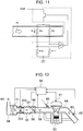
- FIG. 11 is a schematic configuration circuit diagram illustrating the operation principle of the thermal type air flow meter.
- a drive circuit of the thermal type air flow meter is roughly formed of a bridge circuit and a feedback circuit.
- the bridge circuit is constructed by a heat-generating resistor RH for measuring an intake air flow rate, a temperature-sensitive resistor RC for compensating an intake air temperature, and resistors R10 and R11, and a heating current Ih is caused to flow through the heat-generating resistor RH such that a constant temperature difference is maintained between the heat-generating resistor RH and the temperature-sensitive resistor RC, while performing feedback using an operational amplifier OP1, whereby an output signal V2 according to the air flow rate is outputted.
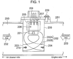
- a primary air passage 250 constituted by an intake pipe constituting member 251 the left side of FIG. 1 corresponds to an air cleaner (not illustrated) side, and the right side thereof corresponds to an engine (not illustrated) side.
- the air flow from the left side of FIG. 1 to the right side thereof is the air flow in the forward direction, is generally referred to as a forward flow 252, and corresponds to a normal air flow when the air is taken into the engine.
- the air flow from the right side of FIG. 1 to the left side thereof is the air flow in the backward direction, and is generally referred to as a backward flow 253.
- the backward flow 253 is less likely to be generated in normal engine operation conditions.
- the intake air is pulsated by opening/closing of an intake/exhaust valve of the engine
- the rotation frequency of the engine and an n-th order wave having a vibration frequency specific to an intake pipe are synchronized with each other in a high-load state where a throttle valve (not illustrated) is opened to a large degree
- the pulsation amplitude of the intake air pulsations becomes larger, and the backward flow 253 is generated.
- Such a phenomenon is generally known.
- thermal type air flow meter is strongly required to enable highly accurate measurement of the intake air flow rate in which the air flow rate of even the backward flow 253 is measured.
- a thermal type air flow meter 200 illustrated in FIG. 1 includes a flow rate detecting element 201 having a function of not only measuring the intake air flow rate but also detecting the flow direction, to thereby measure the air flow rate of the forward flow 252 and the air flow rate of the backward flow 253 in distinction from each other. It should be noted that a known technique is used for a method of measuring the forward flow 252 and the backward flow 253, and hence description of the method is omitted in the present invention.
- the flow rate detecting element 201 is provided inside of a secondary air passage (secondary passage) 202.
- a passage entrance 203 of the secondary air passage 202 is opened so as to be opposed to the forward flow direction, a passage exit 204 thereof is opened so as to be opposed to the backward flow direction, and the secondary air passage 202 has a passage structure that facilitates introduction of each air flow into the secondary air passage 202.
- the flow rate detecting element 201 is mechanically fixed and electrically connected onto a circuit board 205 constituting a drive circuit of the thermal type air flow meter 200, similarly to an electronic circuit component 206 such as an IC chip.
- the circuit board 205 is electrically connected to a connector terminal 208 via an aluminum wire 207, receives inputs from a power supply and a ground, and outputs an air flow rate signal to the outside.
- the thermal type air flow meter 200 is mechanically connected to the intake pipe constituting member 251 by a fixing member such as a screw 209.
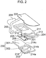
- FIG. 2 is a component development view illustrating a component structure of the thermal type air flow meter illustrated in FIG. 1 .
- the thermal type air flow meter 200 includes, as main components, four components of a housing member 211, a cover member 220, the circuit board 205, and a base member 230.
- the housing member 211 is formed of a molded component of a synthetic resin such as plastic or a metal cast component, and is constituted by a substantially rectangular plate-like member having a predetermined plate thickness.
- the housing member 211 extends in a direction orthogonal to the air flow inside of the intake pipe constituting member 251, and is attached such that both flat surfaces thereof are positioned along the air flow.
- a flange part for fixing the intake pipe constituting member 251 and the connector terminal 208 for electrically connecting the circuit board 205 with an external device are provided in a base end part of the housing member 211.
- the housing member 211 includes: a base member attachment surface on one side, on which the base member 230 is attached; and a cover member attachment surface on another side, on which the cover member 220 is attached.
- An opening hole 212 is formed in the base end part of the housing member 211, and the electronic circuit component 206 on the circuit board 205 fixed to the base member 230 can be inserted into the opening hole 212.
- a housing groove part 213 is provided on the cover member attachment surface in the leading end part of the housing member 211, and the housing groove part 213 forms a second passage part 202B of the secondary air passage 202 in cooperation with the cover member 220.
- the housing groove part 213 is formed so as to extend in the forward flow direction from one side in the shorter-side direction located on the upstream side in the forward flow direction toward another side in the shorter-side direction located on the downstream side in the forward flow direction.
- An upstream-side end of the housing groove part 213 is opened so as to pass through to the base member attachment surface side, and a downstream-side end thereof is formed so as to be continuous up to an end part on the another side in the shorter-side direction.
- the cover member 220 is joined and combined with the cover member attachment surface of the housing member 211, to thereby cover an opened portion of the housing groove part 213, so that the second passage part 202B that is part of the secondary air passage 202 and the passage exit 204 are configured.
- the cover member 220 is formed of a plate-like member by molding a resin or other materials and has a size large enough to cover the opened portion of the housing groove part 213.
- the circuit board 205 is electrically connected to the flow rate detecting element 201, receives an input of the amount of heat radiation from the flow rate detecting element 201, and outputs a signal according to the air flow rate.
- Various electronic circuit components 206 and conductor wiring are placed on the circuit board 205, the flow rate detecting element 201 is also mechanically and electrically connected to the circuit board 205, and the flow rate detecting element 201 is exposed in the secondary air passage 202.
- the base member 230 is a plate-like resin molded component made of a synthetic resin material and includes: a flat plate-like board fixing part 301 to which the circuit board 205 is bonded and fixed; and a secondary passage constituting part 302 that forms a first passage part 202A that is part of the secondary air passage 202.
- the board fixing part 301 has a size appropriate to close the opening hole 212 of the housing member 211 when the board fixing part 301 is attached to the base member attachment surface of the housing member 211, whereby the circuit board 205 is sandwiched and housed between the board fixing part 301 and the housing member 211.
- a base groove part 214 is provided in the secondary passage constituting part 302, and the base groove part 214 forms the first passage part 202A that is part of the secondary air passage 202, in cooperation with the housing member 211 when the base member 230 is joined and combined with the base member attachment surface of the housing member 211.
- the base groove part 214 includes: a passage portion 214a that is provided so as to extend from the upstream side toward the downstream side in the forward flow direction; a passage portion 214b bent toward the board fixing part 301 at an end part of the passage portion 214a; and a passage portion 214c that is bent at an end part of the passage portion 214b and extends from the downstream side toward the upstream side in the forward flow direction along the passage portion 214a.
- the base groove part 214 is formed such that an end part of the passage portion 214c is positioned so as to be opposed to and communicated with the upstream-side end of the housing groove part 213 that is opened so as to pass through the housing member 211.
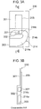
- FIG. 3A to FIG. 5B are views for describing a factor that causes warpage deformation of the base member.
- FIGS. 3A and 3B are views each illustrating only a state where the circuit board 205 is mounted on the base member 230
- FIG. 3A is a view illustrating the base member 230 observed from its surface joined to the housing member 211
- FIG. 3B is a cross-sectional view of FIG. 3A taken along the line A-A.
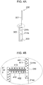
- FIGS. 4A and 4B are views for describing a difference in cooling time between a thin part and a thick part
- FIGS. 5A and 5B are views each illustrating an example of the warpage deformation occurring in the base member.
- FIG. 4A and FIG. 5A are cross-sectional views each corresponding to FIG. 3B
- FIG. 4B and FIG. 5B are enlarged views illustrating a main part of FIG. 4A and a main part of FIG. 5A , respectively.
- the base member 230 is a resin component integrally including the board fixing part 301 and the secondary passage constituting part 302 and is formed by, for example, injection molding.
- injection molding In the case where the thermal type air flow meter 200 is used for an automobile engine, because the usage environment is harsh, it is general to form the base member 230 by injection molding of polybutylene terephthalate (PBT) resin or other resins called engineering plastic.
- PBT polybutylene terephthalate
- the injection molding is a processing method in which a material of the resin is melt at a temperature of 250°C or higher, is injected by applying a pressure so as to fill a molding die, and thus is molded. After the molding, the material of the resin is left until the temperature thereof cools down, and then is taken out as a completed resin component.
- the flat portion 401 as described above is generally molded so as to have a thin resin thickness.
- a resin thickness of the secondary passage constituting part 302 is not constant, and the resin thickness (t2) thereof is larger than the thin resin thickness (t1) of the flat portion 401 (t2 > t1). That is, as illustrated in FIG. 4B , a thin part 411 and a thick part 412 having different resin thicknesses exist in one resin component (base member).
- a wall portion vertical (vertical wall 402) to the bonding surface of the circuit board 205 is illustrated as the thick part 412, but this wall portion does not necessarily correspond to the thick part 412.
- the resin that has been melt at a high temperature is injected into the molding die and thus is molded, and hence if a portion having a different resin thickness exists, there occurs a difference in time until the resin temperature cools down after the molding. That is, as illustrated in FIG. 4B , even if the resin temperature has cooled down in the thin part 411, a phenomenon that the resin temperature has cooled down on the surface of the resin but has not completely cooled down inside thereof occurs in the thick part 412, so that a portion 413 in which cool-down is delayed is generated.
- the left side of the secondary passage constituting part 302 of the base member 230 in FIG. 5A is in a restricted state 501 in which a movement is structurally restricted by a resin wall
- the right side of the secondary passage constituting part 302 in FIG. 5A is in an opened state 502 in which the structure is opened by the base groove part 214 constituting the secondary air passage 202.
- the base member 230 is fixed on the restricted side, and the residual stress is released in the direction in which the base member 230 is opened. Accordingly, the base member 230 has a shape opened on the stress-released side, and as a result, has a shape inclined toward the restricted side (the left side of FIG. 5A ) as illustrated in FIG. 5A , so that deformation called warpage occurs.
- warpage deformation occurs and the warpage amount varies for each base member 230, variations occur in a flow passage area of the secondary air passage 202 and in a distance between an inner wall of the secondary air passage 202 and the flow rate detecting element 201, and these variations may affect the measuring accuracy of the flow rate.
- the warpage deformation of the base member 230 may affect the joining to the housing member 211 and the bonding property of the circuit board 205. Accordingly, it is necessary to minimize as far as possible the warpage deformation of the base member 230 at the time of the molding.
- FIGS. 6A, 6B, and 6C are views each illustrating an example being useful for understanding the invention of the base member
- FIG. 6A is a front view illustrating the base member observed from its surface joined to the housing member
- FIG. 6B is a side view observed from the upstream side in the forward flow direction
- FIG. 6C is a plan view.
- the base member 230 is provided with a rib 231 as a reinforcing structure for enhancing the strength of the base member 230.
- the rib 231 is molded at the same time as the base member 230 with the use of the same resin material and the molding die.
- the circuit board 205 (illustrated by a dotted line) on which the flow rate detecting element 201 is placed and the base member 230 are bonded and fixed to each other (an adhesive is not illustrated), and the rib 231 is provided such that a rear surface thereof faces the bonding surface of the circuit board 205.
- the rib 231 is provided so as to protrude from an outer surface of the board fixing part 301 on a side thereof opposite to the housing member 211, and the rib 231 is set at a connection portion between the thin board fixing part 301 to which the circuit board 205 is bonded and the thick secondary passage constituting part 302 in which the wall surface of the first passage part 202A is formed, so as to join together the two parts.
- the rib 231 is formed so as to protrude from the outer surface of the board fixing part 301 at a central position in the shorter-side direction of the base member 230 and extend from the base end part to the leading end part of the board fixing part 301. Accordingly, for example, in the case where the residual stress that causes the warpage as illustrated in FIG. 5A is applied, the rib 231 serves to prop the structure, whereby the warpage of the base member 230 can be suppressed.
- FIGS. 7A, 7B, 7C, and 7D are views each illustrating another example being useful for understanding the invention of the base member
- FIG. 7A is a front view illustrating the base member observed from its surface joined to the housing member
- FIG. 7B is a side view observed from the upstream side in the forward flow direction
- FIG. 7C is a plan view
- FIG. 7D is a cross-sectional view of FIG. 7A taken along the line B-B.
- a characteristic feature of the present example is that a rib 232 is provided as a reinforcing structure, and the rib 232 extends from the board fixing part 301 to the vicinity of a flow rate measuring part of the secondary passage constituting part 302. It should be noted that constituent elements similar to those in the above-mentioned embodiment are denoted by the same reference symbols, to thereby omit detailed description thereof. In addition, in FIGS. 7A to 7D , illustration of the circuit board 205 and the flow rate detecting element 201 is omitted.
- the flow rate detecting element 201 of the thermal type air flow meter 200 is placed in the secondary air passage 202, it is necessary to measure a stable flow of a fluid to be measured.
- the narrowest portion in which a cross-sectional area inside of the secondary air passage 202 is the narrowest is used as a flow rate measuring part, and the flow rate detecting element 201 is placed in the flow rate measuring part.
- An example of the generally-adopted method includes providing a narrowed-down part 215 inside of the secondary air passage 202 to thereby temporarily narrow down the flow.
- the narrowed-down part 215 is provided inside of the secondary air passage 202 is illustrated in FIGS. 7A to 7D .
- the narrowed-down part 215 has a convex shape that protrudes inside of the secondary air passage 202 at a substantially central position of the passage portion 214c of the base groove part 214, and narrows the flow passage area of the secondary air passage 202 in the width direction.
- an outer wall portion of the secondary passage constituting part 302 corresponding to a rear surface of the narrowed-down part 215 has a concave shape.
- the present example adopts a structure in which the rib 232 extends up to the outer wall portion. With this structure, one continuous rib 232 passes from the board fixing part 301 to the vicinity of the flow rate measuring part. Accordingly, it is possible to achieve stabilization of the fluid to be measured inside of the secondary air passage 202 as well as further enhancement in strength of the base member 230.
- the rib 232 extends up to the vicinity of the flow rate measuring part, variations in the flow rate measuring accuracy can be suppressed.
- Dimension changes such as the cross-sectional area of the flow rate measuring part inside of the secondary air passage 202 and the distance between the flow passage wall and the flow rate detecting element 201 quickly affect the flow rate measuring accuracy. It is preferable that the flow rate detecting element 201 measure the air flow in a stable state, and hence the flow rate detecting element 201 is set at a position having the narrowest cross-sectional area inside of the secondary air passage 202.
- the cross-sectional area near the passage entrance 203 and the passage exit 204 of the secondary air passage 202 is larger than that of the flow rate measuring part, and hence even if a dimension variation of ⁇ 0.1 mm exists, a change in the passage cross-sectional area is small. In contrast, even with the same dimension change of ⁇ 0.1 mm, a change in the cross-sectional area of the flow rate measuring part in which the passage cross-sectional area is the narrowest is relatively large compared with those of the passage entrance 203 and the like of the secondary air passage 202, so that a flow rate measuring error accordingly becomes larger.
- the flow rate measuring accuracy can be enhanced by reducing such a dimension change near the flow rate detecting element 201.
- the rib 232 extends up to the vicinity of the flow rate measuring part inside of the secondary air passage 202, the rigidity of the flow rate measuring part is high, and a change in shape and dimensions of the flow rate measuring part can be reduced, so that the variations in the flow rate measuring accuracy can be suppressed.
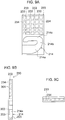
- FIGS. 8A, 8B, 8C, and 8D are views each illustrating still another example being useful for understanding the invention of the base member
- FIG. 8A is a front view illustrating the base member observed from its surface joined to the housing member
- FIG. 8B is a side view observed from the upstream side in the forward flow direction
- FIG. 8C is a plan view
- FIG. 8D is a cross-sectional view of FIG. 8A taken along the line C-C.
- a characteristic feature of the present example is that a rib 233 is provided with a hollowed-out part 234 for making the resin thickness of the base member 230 even, and the hollowed-out parts 234 are provided at a plurality of points.
- the hollowed-out parts 234 are provided at totally six points, that is, five points in the board fixing part 301 and one point in the secondary passage constituting part 302, but the number of the hollowed-out parts 234 is not particularly limited.
- the rib 233 is formed so as to extend up to the rear surface of the narrowed-down part 215. Because the base member 230 is provided with the hollowed-out part 234, a thick part formed by the rib 233 is removed, the resin thickness of the entire base member 230 is made even, a difference in time until the resin cools down from high temperature is eliminated, and the dimension accuracy can be secured.
- the hollowed-out part 234 thus provided to the rib 233 further advantageously serves to enhance the dimension accuracy of the base member 230.
- the rib 233 provided to the base member 230 serves to enhance the strength of the base member 230, but partially forms a thick part on the base member 230.
- the thick part causes a difference in cooling time until the resin cools down from high temperature after the molding, between the thick part and the thin part, and distortion may occur in the base member 230.
- the rib 233 is provided with the hollowed-out part 2344, the thick part is removed from the base member 230, a difference in time until the resin cools down from high temperature is eliminated, and the dimension accuracy can be secured.
- FIGS. 9A, 9B, and 9C are views each illustrating an embodiment of the base member
- FIG. 9A is a front view illustrating the base member observed from its surface joined to the housing member
- FIG. 9B is a side view observed from the upstream side in the forward flow direction
- FIG. 9C is a plan view.
- a characteristic feature of the present embodiment is that the ribs 233 and the hollowed-out parts 234 as illustrated in FIG. 8 are provided over an entire outer surface of the board fixing part 301.
- the plurality of ribs 233 and the plurality of hollowed-out parts 234 are provided only on the outer surface of the board fixing part 301, but the ribs 233 and the hollowed-out parts 234 may be placed similarly on an outer surface of the secondary passage constituting part.
- the ribs 233 are provided in a grid pattern, and hence the dimension accuracy of the base member 230 can be further enhanced.
- even the same dimension change of ⁇ 0.1 mm has a large influence on the flow rate measuring part and has a small influence on the passage entrance 203 and the passage exit 204 of the secondary air passage 202.
- the flow rate measuring accuracy is further enhanced. Accordingly, as illustrated in FIGS. 9A to 9C , the ribs 233 are provided in the grid pattern, and the dimension accuracy of the entire base member 230 is enhanced, whereby the flow rate measuring accuracy of the thermal type air flow meter 200 can be further enhanced.
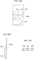
- FIGS. 10A, 10B, and 10C are views each illustrating still another example being useful for understanding the invention of the base member 230
- FIG. 10A is a front view illustrating the base member observed from its surface joined to the housing member
- FIG. 10B is a side view observed from the upstream side in the forward flow direction
- FIG. 10C is a plan view.
- a characteristic feature of the present example is that a rib 235 serving as a reinforcing structure is partially provided at the connection portion between the board fixing part 301 and the secondary passage constituting part 302 of the base member 230.
- the rib 235 is provided so as to be interposed between the outer surface of the board fixing part 301 and a vertical surface of the secondary passage constituting part 302 that erects at an end part of the board fixing part 301, and the rib 235 has a right triangle shape that is inclined so as to gradually approach the secondary passage constituting part 302 toward a side farther from the outer surface of the board fixing part 301.
- a plurality of the ribs 235 are provided at a predetermined interval in the shorter-side direction of the base member 230 corresponding to the forward flow direction, and in the present example, the ribs 235 are provided at totally three points. Even with the rib 235 having such a simple structure, a sufficient effect of suppressing warpage deformation of the base member 230 can be obtained.
- the number of the ribs 235 is three but is not limited thereto as long as the effect can be obtained, and hence the number thereof may be increased or decreased.
- FIG. 12 is a view illustrating an embodiment in which the present invention is applied to an electronic fuel injection type internal combustion engine.
- Intake air 67 taken in from an air cleaner 54 passes through the intake pipe constituting member 251 of the thermal type air flow meter 200, an intake duct 55, a throttle body 58, and an intake manifold 59 including an injector 60 to which fuel is supplied, and then, the intake air 67 is taken into an engine cylinder 62.
- exhaust gas 63 generated in the engine cylinder 62 is discharged through an exhaust manifold 64.
- a control unit 66 receives inputs of: an air flow rate signal and a pressure signal outputted from the circuit board 205 of the thermal type air flow meter 200; an intake air temperature signal outputted from a temperature sensor; a throttle valve angle signal outputted from a throttle angle sensor 57; an oxygen concentration signal outputted from an oxygen concentration meter 65 provided to the exhaust manifold 64; an engine rotation speed signal outputted from a rotation speed meter 61; and other signals.
- the control unit 66 performs sequential arithmetic processing on these signals, to thereby obtain an optimal fuel injection amount and an optimal opening degree of an idle air control valve, and controls the injector 60 and the idle air control valve by using the obtained values.
- the plate-like base member 230 is formed by molding a synthetic resin material, and one or more ribs 231 that are integrally formed by using the same resin material as that of the base member 230 are provided on the outer surface of the board fixing part 301 to which the circuit board 205 is bonded and fixed, so that the strength of the base member 230 is enhanced. Accordingly, even in the case where both the thin part 411 and the thick part 412 exist in the base member 230 formed of a single component and thermal contraction is uneven therebetween at the time of the molding, it is possible to suppress warpage deformation of the base member 230 occurring at a boundary between the thick part 412 and the thin part 411.
- the present invention can be variously changed.
- an element capable of measuring an intake air flow rate and also measuring an air flow direction at the same time may be used as the flow rate detecting element 201.
- a thermal type air flow meter having a function of only measuring a flow rate in a single direction does not need to have the complicated secondary air passage structure, and for example, even the secondary air passage structure as described in JP Patent No. 3523022 fulfills a function as the secondary air passage.
- effects of the present invention are more advantageous.
- fixing screw 210 ... air flow inside of secondary air passage, 211 ... housing member, 220 ... cover member, 230 ... resin base member, 231 ... rib, 233 ... rib, 234 ... hollowed-out part, 235 ... rib, 250 ... primary air passage, 251 ... intake pipe constituting member, 252 ... forward flow inside of primary air passage, 253 ... backward flow inside of primary air passage
Description
- The present invention relates to a thermal type air flow meter that measures the flow rate of air, for example, to a thermal type air flow meter that is attached to an intake pipe of an internal combustion engine and measures the flow rate of intake air supplied to an engine.
- A thermal type air flow meter that measures the flow rate of intake air supplied to an internal combustion engine is attached for use to part of an intake system of an internal combustion engine. The thermal type air flow meter has a mechanism of, for example, causing a flow rate detecting element such as a heat-generating resistor to generate heat and measuring the flow rate of passing air on the basis of the amount of heat radiation therefrom to the air. Accordingly, it is necessary to consider protection of the flow rate detecting element from contaminating substances and other factors during long-term use and securement of the flow rate measuring accuracy. Further, it is also necessary to consider intake air pulsations such as a backward flow that are generated in an intake pipe of the internal combustion engine when the intake air is pulsated by opening/closing of an intake/exhaust valve of an engine and the intake pipe resonates with the rotation frequency of the engine.
- In a conventional thermal type air flow meter included in an internal combustion engine,
JP Patent No. 3523022 - In addition, with regard to a thermal type air flow meter having such a rib structure as described in the present invention, JP Patent Publication (Kokai) No.
05-302839 A (1993 2002-107201 A US 6 182 639 B 1 describes a thermal-type airflow meter that comprises an airflow meter body and a measuring part. Both of the frame of a housing which accommodates the electronic circuit, and a sub-passage member which has the heating resistor positioned within a sub-passage, are arranged on a metallic base. Further, the frame, the sub-passage member, the metallic base and the cover are each fixedly attached to at least two respective different members. A connector of the housing, the frame and the sub-passage member are formed in a flat shape to form the measuring module. The measuring module is inserted through an insertion hole to locate the heating resistor within the main air passage, and the fixing flange of the housing is fixedly attached to the airflow meter body.GB 2 393 254 A - A thermal type air flow meter measures a backward flow in a state where a detecting element is placed inside of a secondary air passage, and hence the secondary air passage of the thermal type air flow meter is required to have a complicated structure including a bent passage part and a narrowed-down shape. Meanwhile, a reduction in cost of the thermal type air flow meter is demanded from the market at the same time. That is, it is necessary to overcome a contradictory problem that the complicated structure is required while the reduction in cost is aimed at at the same time.
- In order to achieve the complicated structure of the secondary air passage, a conceivable idea involves increasing the number of components and combining the components to thereby constitute the secondary air passage. The increase in the number of components, however, leads to an increase in cost, and in order to achieve the reduction in cost, it is necessary to achieve the complicated structure without increasing the number of components. This enables not only a reduction in cost of the components but also a reduction in assembly man-hours, so that it is possible to reduce cost of the thermal type air flow meter or suppress an increase in cost thereof.
- Taking the structure described in
JP Patent No. 3523022 - Among the six components, components mainly constituting the secondary air passage are two components of a portion of the metal base and the secondary air passage member. The secondary air passage member is formed by resin molding, and hence a complicated passage structure is easy to achieve.
- In contrast, the metal base is a component having the portion that constitutes the secondary air passage and also having another portion that has a function of bonding and fixing the circuit board, the housing, and other components. In addition, the metal base is formed by pressing a flat plate-like metal material, and hence the metal base is advantageous to maintain a flat surface for the bonding and the like but is disadvantageous to achieve the complicated structure of the secondary air passage.
- Accordingly, it is conceivable to form by resin molding only a portion of the secondary air passage constituted by the metal base member similarly to the secondary air passage member, but in order to place the flow rate detecting element inside of the secondary air passage, this portion needs to be newly prepared as a separate component, resulting in the increase in the number of components and the increase in assembly man-hours, and the increase in cost of the thermal type air flow meter cannot be avoided.
- In order to solve these problems, it is conceivable to form the metal base as a resin base by resin molding, but the resin easily becomes thicker in the portion of the secondary air passage having the complicated structure, whereas the portion for bonding and fixing the circuit board, the housing, and other components is desired to be thin.
- Under the circumstance, if such a thick part and such a thin part are formed as the same molded component, thermal contraction becomes uneven between the thick part and the thin part at the time of the molding, and a warpage phenomenon may occur at a boundary between the thick part and the thin part. This warpage deformation causes a trouble in bonding properties of the housing and the circuit board, and moreover, variations in a warpage amount lead to variations in a shape of a flow rate measuring unit. As a result, a new problem arises that the flow rate measuring accuracy also varies.
- The present invention has been made in view of the above-mentioned points, and therefore has an object to provide a thermal type air flow meter that is capable of suppressing deformation of a base member at the time of molding, to thereby secure dimension accuracy and reduce an influence of a dimension change on measuring accuracy, thus enabling highly accurate measurement of an air flow rate.
- In order to solve the above-mentioned problems, the present invention provides a thermal type air flow meter having the features of
independent claim 1. Preferred embodiments of the invention are described in the dependent claims. - According to an aspect of the invention, there can be provided a thermal type air flow meter including: a housing member placed in an intake passage of an internal combustion engine; a plate-like base member that is fixed to the housing member and includes a secondary passage into which part of air passing through the intake passage flows; a flow rate detecting element placed in the secondary passage; and a circuit board that is electrically connected to the flow rate detecting element, receives an input of an amount of heat radiation from the flow rate detecting element, and outputs a signal according to an air flow rate. The base member is formed of a synthetic resin material and includes: a board fixing part to which the circuit board is fixed; a secondary passage constituting part that is integrally formed so as to be continuous with a leading end part of the board fixing part and constitutes the secondary passage in cooperation with the housing member; and/or a reinforcing structure that is provided at at least a connection portion between the board fixing part and the secondary passage constituting part and enhances strength of the base member.
- With the thermal type air flow meter according to this aspect, the base member is formed of the synthetic resin material and includes: the board fixing part to which the circuit board is fixed; the secondary passage constituting part that is integrally formed so as to be continuous with the leading end part of the board fixing part and constitutes the secondary passage in cooperation with the housing member; and the reinforcing structure that is provided at at least the connection portion between the board fixing part and the secondary passage constituting part and enhances the strength of the base member. Accordingly, the strength of the flat plate-like base member is enhanced by the reinforcing structure.
- As a result, at the time of molding the base member including: the board fixing part formed of a thin part having a substantially constant resin thickness; and the secondary passage constituting part including a thick part for forming the secondary passage, even in the case where thermal contraction is uneven between the thin part and the thick part, warpage deformation of the base member occurring at a boundary between the thick part and the thin part can be suppressed.
- According to another aspect of the invention, there can be provided a thermal type air flow meter comprising: a housing member placed in an intake passage of an internal combustion engine; a base member that is fixed to the housing member and includes a secondary passage into which part of air passing through the intake passage flows; a flow rate detecting element placed in the secondary passage; and a circuit board that is electrically connected to the flow rate detecting element, receives an input of an amount of heat radiation from the flow rate detecting element, and outputs a signal according to an air flow rate, wherein the base member is a plate-like resin molded component formed of a synthetic resin material and includes: a board fixing part to which the circuit board is fixed; a secondary passage constituting part that is integrally formed so as to be continuous with a leading end part of the board fixing part and constitutes the secondary passage in cooperation with the housing member; and a reinforcing structure that is provided at at least a connection portion between the board fixing part and the secondary passage constituting part and enhances strength of the base member.
- The secondary passage constituting part may include a flow rate measuring part having therein the flow rate detecting element placed in the secondary passage, and the rib may extend from the board fixing part to a vicinity of the flow rate measuring part.
- The flow rate measuring part may include a narrowed-down part that narrows a flow passage area of the secondary passage.
- The rib may include a hollowed-out part that makes a resin thickness of the base member even.
- The rib may include a plurality of the hollowed-out parts at a predetermined interval in a longer-side direction of the rib.
- The secondary passage constituting part may include a base groove part formed on a surface thereof opposed to the housing member, and an opened portion of the base groove part and the housing member covering the opened portion constitute the secondary passage in cooperation with each other.
- The flow rate detecting element may comprise an element capable of measuring an intake air flow rate and also measuring an air flow direction.
- The flow rate detecting element may be joined to the circuit board by bonding.
- According to another aspect, there can be provided a fuel injection system for an internal combustion engine comprising the thermal type air flow meter according to any of the above aspects.
- According to the present invention, it is possible to prevent a trouble of attachment to the housing member and a trouble of attachment of the circuit board due to the warpage deformation and also possible to prevent variations in the flow rate measuring accuracy.
-
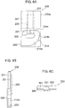
-
FIG. 1 is a cross-sectional view illustrating a thermal type air flow meter according to an example being useful for understanding the invention. -
FIG. 2 is a development view illustrating components ofFIG. 1 . -
FIGS. 3A and 3B are views each illustrating a conventional base member,FIG. 3A is a view illustrating the base member observed from its surface joined to a housing member, andFIG. 3B is a cross-sectional view ofFIG. 3A taken along the line A-A. -
FIGS. 4A and 4B are views for describing a difference in cooling time between a thin part and a thick part,FIG. 4A is a cross-sectional view corresponding toFIG. 3B , andFIG. 4B is an enlarged view illustrating a main part ofFIG. 4A . -
FIGS. 5A and 5B are views each illustrating an example of warpage deformation occurring in a base member,FIG. 5A is a cross-sectional view corresponding toFIG. 3B , andFIG. 5B is an enlarged view illustrating a main part ofFIG. 5A . -
FIGS. 6A, 6B, and 6C are views each illustrating an example being useful for understanding the invention,FIG. 6A is a front view illustrating the base member observed from its surface joined to the housing member,FIG. 6B is a side view observed from an upstream side in a forward flow direction, andFIG. 6C is a plan view. -
FIGS. 7A, 7B, 7C, and 7D are views each illustrating another example being useful for understanding the invention,FIG. 7A is a front view illustrating the base member observed from its surface joined to the housing member,FIG. 7B is a side view observed from the upstream side in the forward flow direction,FIG. 7C is a plan view, andFIG. 7D is a cross-sectional view ofFIG. 7A taken along the line B-B. -
FIGS. 8A, 8B, 8C, and 8D are views each illustrating still another example being useful for understanding the invention,FIG. 8A is a front view illustrating the base member observed from its surface joined to the housing member,FIG. 8B is a side view observed from the upstream side in the forward flow direction,FIG. 8C is a plan view, andFIG. 8D is a cross-sectional view ofFIG. 8A taken along the line C-C. -
FIGS. 9A, 9B, and 9C are views each illustrating an embodiment,FIG. 9A is a front view illustrating the base member observed from its surface joined to the housing member,FIG. 9B is a side view observed from the upstream side in the forward flow direction, andFIG. 9C is a plan view. -
FIGS. 10A, 10B, and 10C are views each illustrating still another example being useful for understanding the invention,FIG. 10A is a front view illustrating the base member observed from its surface joined to the housing member,FIG. 10B is a side view observed from the upstream side in the forward flow direction, andFIG. 10C is a plan view. -
FIG. 11 is a diagram illustrating an operation principle of the thermal type air flow meter. -
FIG. 12 is a view illustrating a control system of an internal combustion engine. - Examples being useful for understanding the invention and Embodiments of the present invention are described in detail with reference to the attached drawings.
- First, an operation principle of a representative thermal type air flow meter including a heat-generating resistor is described as an example of an intake air measuring apparatus.
-
FIG. 11 is a schematic configuration circuit diagram illustrating the operation principle of the thermal type air flow meter. - A drive circuit of the thermal type air flow meter is roughly formed of a bridge circuit and a feedback circuit. The bridge circuit is constructed by a heat-generating resistor RH for measuring an intake air flow rate, a temperature-sensitive resistor RC for compensating an intake air temperature, and resistors R10 and R11, and a heating current Ih is caused to flow through the heat-generating resistor RH such that a constant temperature difference is maintained between the heat-generating resistor RH and the temperature-sensitive resistor RC, while performing feedback using an operational amplifier OP1, whereby an output signal V2 according to the air flow rate is outputted. Specifically, in the case where the flow rate is high, an amount of heat taken away from the heat-generating resistor RH is large, and hence a larger amount of the heating current Ih is caused to flow. In contrast to this, in the case where the flow rate is low, the amount of heat taken away from the heat-generating resistor RH is small, and hence the amount of the heating current Ih can be small.
- Next, a configuration of a thermal type air flow meter according to an example being useful for understanding the present invention is described with reference to
FIG. 1 . - In a
primary air passage 250 constituted by an intakepipe constituting member 251, the left side ofFIG. 1 corresponds to an air cleaner (not illustrated) side, and the right side thereof corresponds to an engine (not illustrated) side. With regard to an air flow direction, the air flow from the left side ofFIG. 1 to the right side thereof is the air flow in the forward direction, is generally referred to as aforward flow 252, and corresponds to a normal air flow when the air is taken into the engine. - In contrast to this, the air flow from the right side of
FIG. 1 to the left side thereof is the air flow in the backward direction, and is generally referred to as abackward flow 253. Thebackward flow 253 is less likely to be generated in normal engine operation conditions. In the state where the intake air is pulsated by opening/closing of an intake/exhaust valve of the engine, if the rotation frequency of the engine and an n-th order wave having a vibration frequency specific to an intake pipe are synchronized with each other in a high-load state where a throttle valve (not illustrated) is opened to a large degree, the pulsation amplitude of the intake air pulsations becomes larger, and thebackward flow 253 is generated. Such a phenomenon is generally known. - In recent years, for exhaust gas regulations and reduced fuel consumption, there is a demand to measure with high accuracy the intake air flow rate. The thermal type air flow meter is strongly required to enable highly accurate measurement of the intake air flow rate in which the air flow rate of even the
backward flow 253 is measured. - Similarly, a thermal type
air flow meter 200 illustrated inFIG. 1 includes a flowrate detecting element 201 having a function of not only measuring the intake air flow rate but also detecting the flow direction, to thereby measure the air flow rate of theforward flow 252 and the air flow rate of thebackward flow 253 in distinction from each other. It should be noted that a known technique is used for a method of measuring theforward flow 252 and thebackward flow 253, and hence description of the method is omitted in the present invention. - The flow
rate detecting element 201 is provided inside of a secondary air passage (secondary passage) 202. Apassage entrance 203 of thesecondary air passage 202 is opened so as to be opposed to the forward flow direction, apassage exit 204 thereof is opened so as to be opposed to the backward flow direction, and thesecondary air passage 202 has a passage structure that facilitates introduction of each air flow into thesecondary air passage 202. The flowrate detecting element 201 is mechanically fixed and electrically connected onto acircuit board 205 constituting a drive circuit of the thermal typeair flow meter 200, similarly to anelectronic circuit component 206 such as an IC chip. - The
circuit board 205 is electrically connected to aconnector terminal 208 via analuminum wire 207, receives inputs from a power supply and a ground, and outputs an air flow rate signal to the outside. The thermal typeair flow meter 200 is mechanically connected to the intakepipe constituting member 251 by a fixing member such as ascrew 209. -
FIG. 2 is a component development view illustrating a component structure of the thermal type air flow meter illustrated inFIG. 1 . - The thermal type
air flow meter 200 includes, as main components, four components of ahousing member 211, acover member 220, thecircuit board 205, and abase member 230. - The
housing member 211 is formed of a molded component of a synthetic resin such as plastic or a metal cast component, and is constituted by a substantially rectangular plate-like member having a predetermined plate thickness. Thehousing member 211 extends in a direction orthogonal to the air flow inside of the intakepipe constituting member 251, and is attached such that both flat surfaces thereof are positioned along the air flow. A flange part for fixing the intakepipe constituting member 251 and theconnector terminal 208 for electrically connecting thecircuit board 205 with an external device are provided in a base end part of thehousing member 211. - The
housing member 211 includes: a base member attachment surface on one side, on which thebase member 230 is attached; and a cover member attachment surface on another side, on which thecover member 220 is attached. Anopening hole 212 is formed in the base end part of thehousing member 211, and theelectronic circuit component 206 on thecircuit board 205 fixed to thebase member 230 can be inserted into theopening hole 212. Ahousing groove part 213 is provided on the cover member attachment surface in the leading end part of thehousing member 211, and thehousing groove part 213 forms asecond passage part 202B of thesecondary air passage 202 in cooperation with thecover member 220. - The
housing groove part 213 is formed so as to extend in the forward flow direction from one side in the shorter-side direction located on the upstream side in the forward flow direction toward another side in the shorter-side direction located on the downstream side in the forward flow direction. An upstream-side end of thehousing groove part 213 is opened so as to pass through to the base member attachment surface side, and a downstream-side end thereof is formed so as to be continuous up to an end part on the another side in the shorter-side direction. Then, thecover member 220 is joined and combined with the cover member attachment surface of thehousing member 211, to thereby cover an opened portion of thehousing groove part 213, so that thesecond passage part 202B that is part of thesecondary air passage 202 and thepassage exit 204 are configured. - The
cover member 220 is formed of a plate-like member by molding a resin or other materials and has a size large enough to cover the opened portion of thehousing groove part 213. - The
circuit board 205 is electrically connected to the flowrate detecting element 201, receives an input of the amount of heat radiation from the flowrate detecting element 201, and outputs a signal according to the air flow rate. Variouselectronic circuit components 206 and conductor wiring (no reference symbol) are placed on thecircuit board 205, the flowrate detecting element 201 is also mechanically and electrically connected to thecircuit board 205, and the flowrate detecting element 201 is exposed in thesecondary air passage 202. - The
base member 230 is a plate-like resin molded component made of a synthetic resin material and includes: a flat plate-likeboard fixing part 301 to which thecircuit board 205 is bonded and fixed; and a secondarypassage constituting part 302 that forms a first passage part 202A that is part of thesecondary air passage 202. - The
board fixing part 301 has a size appropriate to close theopening hole 212 of thehousing member 211 when theboard fixing part 301 is attached to the base member attachment surface of thehousing member 211, whereby thecircuit board 205 is sandwiched and housed between theboard fixing part 301 and thehousing member 211. - A
base groove part 214 is provided in the secondarypassage constituting part 302, and thebase groove part 214 forms the first passage part 202A that is part of thesecondary air passage 202, in cooperation with thehousing member 211 when thebase member 230 is joined and combined with the base member attachment surface of thehousing member 211. - The
base groove part 214 includes: apassage portion 214a that is provided so as to extend from the upstream side toward the downstream side in the forward flow direction; apassage portion 214b bent toward theboard fixing part 301 at an end part of thepassage portion 214a; and apassage portion 214c that is bent at an end part of thepassage portion 214b and extends from the downstream side toward the upstream side in the forward flow direction along thepassage portion 214a. Thebase groove part 214 is formed such that an end part of thepassage portion 214c is positioned so as to be opposed to and communicated with the upstream-side end of thehousing groove part 213 that is opened so as to pass through thehousing member 211. -
FIG. 3A to FIG. 5B are views for describing a factor that causes warpage deformation of the base member.FIGS. 3A and 3B are views each illustrating only a state where thecircuit board 205 is mounted on thebase member 230,FIG. 3A is a view illustrating thebase member 230 observed from its surface joined to thehousing member 211, andFIG. 3B is a cross-sectional view ofFIG. 3A taken along the line A-A.FIGS. 4A and 4B are views for describing a difference in cooling time between a thin part and a thick part, andFIGS. 5A and 5B are views each illustrating an example of the warpage deformation occurring in the base member.FIG. 4A andFIG. 5A are cross-sectional views each corresponding toFIG. 3B , andFIG. 4B andFIG. 5B are enlarged views illustrating a main part ofFIG. 4A and a main part ofFIG. 5A , respectively. - The
base member 230 is a resin component integrally including theboard fixing part 301 and the secondarypassage constituting part 302 and is formed by, for example, injection molding. In the case where the thermal typeair flow meter 200 is used for an automobile engine, because the usage environment is harsh, it is general to form thebase member 230 by injection molding of polybutylene terephthalate (PBT) resin or other resins called engineering plastic. - The injection molding is a processing method in which a material of the resin is melt at a temperature of 250°C or higher, is injected by applying a pressure so as to fill a molding die, and thus is molded. After the molding, the material of the resin is left until the temperature thereof cools down, and then is taken out as a completed resin component.
- In general, if a resin thickness is made larger in a
flat portion 401 that extends in a flat plate-like pattern at a constant plate thickness, such as theboard fixing part 301, slight irregularities called a sink occur after the molding. Accordingly, theflat portion 401 as described above is generally molded so as to have a thin resin thickness. - In contrast to this, in the secondary
passage constituting part 302, it is necessary to form not only theflat portion 401 but also avertical wall 402 that erects vertically from theflat portion 401, and hence the shape of the secondarypassage constituting part 302 is complicated. Accordingly, a resin thickness of the secondarypassage constituting part 302 is not constant, and the resin thickness (t2) thereof is larger than the thin resin thickness (t1) of the flat portion 401 (t2 > t1). That is, as illustrated inFIG. 4B , athin part 411 and athick part 412 having different resin thicknesses exist in one resin component (base member). - In
FIG. 4B , for ease of description, a wall portion vertical (vertical wall 402) to the bonding surface of thecircuit board 205 is illustrated as thethick part 412, but this wall portion does not necessarily correspond to thethick part 412. - As described above, in the case of the injection molding, the resin that has been melt at a high temperature is injected into the molding die and thus is molded, and hence if a portion having a different resin thickness exists, there occurs a difference in time until the resin temperature cools down after the molding. That is, as illustrated in
FIG. 4B , even if the resin temperature has cooled down in thethin part 411, a phenomenon that the resin temperature has cooled down on the surface of the resin but has not completely cooled down inside thereof occurs in thethick part 412, so that aportion 413 in which cool-down is delayed is generated. - If there occurs a difference in time until the resin temperature cools down between the
thin part 411 and thethick part 412 in this way, even when the resin temperature has completely cooled down, a residual stress remains inside of the resin. If such a residual stress remains, deformation called warpage occurs in the shape of thebase member 230 as illustrated in, for example,FIG. 5A . - For example, in the structure as illustrated in
FIG. 5A , the left side of the secondarypassage constituting part 302 of thebase member 230 inFIG. 5A is in a restrictedstate 501 in which a movement is structurally restricted by a resin wall, whereas the right side of the secondarypassage constituting part 302 inFIG. 5A is in an openedstate 502 in which the structure is opened by thebase groove part 214 constituting thesecondary air passage 202. - For this reason, due to an influence of the residual stress, the
base member 230 is fixed on the restricted side, and the residual stress is released in the direction in which thebase member 230 is opened. Accordingly, thebase member 230 has a shape opened on the stress-released side, and as a result, has a shape inclined toward the restricted side (the left side ofFIG. 5A ) as illustrated inFIG. 5A , so that deformation called warpage occurs. - If such warpage deformation occurs and the warpage amount varies for each
base member 230, variations occur in a flow passage area of thesecondary air passage 202 and in a distance between an inner wall of thesecondary air passage 202 and the flowrate detecting element 201, and these variations may affect the measuring accuracy of the flow rate. In addition, the warpage deformation of thebase member 230 may affect the joining to thehousing member 211 and the bonding property of thecircuit board 205. Accordingly, it is necessary to minimize as far as possible the warpage deformation of thebase member 230 at the time of the molding. -
FIGS. 6A, 6B, and 6C are views each illustrating an example being useful for understanding the invention of the base member,FIG. 6A is a front view illustrating the base member observed from its surface joined to the housing member,FIG. 6B is a side view observed from the upstream side in the forward flow direction, andFIG. 6C is a plan view. - The
base member 230 is provided with arib 231 as a reinforcing structure for enhancing the strength of thebase member 230. According to the same molding method as that of thebase member 230, therib 231 is molded at the same time as thebase member 230 with the use of the same resin material and the molding die. - The circuit board 205 (illustrated by a dotted line) on which the flow
rate detecting element 201 is placed and thebase member 230 are bonded and fixed to each other (an adhesive is not illustrated), and therib 231 is provided such that a rear surface thereof faces the bonding surface of thecircuit board 205. Specifically, therib 231 is provided so as to protrude from an outer surface of theboard fixing part 301 on a side thereof opposite to thehousing member 211, and therib 231 is set at a connection portion between the thinboard fixing part 301 to which thecircuit board 205 is bonded and the thick secondarypassage constituting part 302 in which the wall surface of the first passage part 202A is formed, so as to join together the two parts. - In the present example, the
rib 231 is formed so as to protrude from the outer surface of theboard fixing part 301 at a central position in the shorter-side direction of thebase member 230 and extend from the base end part to the leading end part of theboard fixing part 301. Accordingly, for example, in the case where the residual stress that causes the warpage as illustrated inFIG. 5A is applied, therib 231 serves to prop the structure, whereby the warpage of thebase member 230 can be suppressed. -
FIGS. 7A, 7B, 7C, and 7D are views each illustrating another example being useful for understanding the invention of the base member,FIG. 7A is a front view illustrating the base member observed from its surface joined to the housing member,FIG. 7B is a side view observed from the upstream side in the forward flow direction,FIG. 7C is a plan view, andFIG. 7D is a cross-sectional view ofFIG. 7A taken along the line B-B. - A characteristic feature of the present example is that a
rib 232 is provided as a reinforcing structure, and therib 232 extends from theboard fixing part 301 to the vicinity of a flow rate measuring part of the secondarypassage constituting part 302. It should be noted that constituent elements similar to those in the above-mentioned embodiment are denoted by the same reference symbols, to thereby omit detailed description thereof. In addition, inFIGS. 7A to 7D , illustration of thecircuit board 205 and the flowrate detecting element 201 is omitted. - In the case where the flow
rate detecting element 201 of the thermal typeair flow meter 200 is placed in thesecondary air passage 202, it is necessary to measure a stable flow of a fluid to be measured. In a general method adopted for this purpose, the narrowest portion in which a cross-sectional area inside of thesecondary air passage 202 is the narrowest is used as a flow rate measuring part, and the flowrate detecting element 201 is placed in the flow rate measuring part. An example of the generally-adopted method includes providing a narrowed-downpart 215 inside of thesecondary air passage 202 to thereby temporarily narrow down the flow. - The example in which the narrowed-down
part 215 is provided inside of thesecondary air passage 202 is illustrated inFIGS. 7A to 7D . As illustrated inFIG. 7D , the narrowed-downpart 215 has a convex shape that protrudes inside of thesecondary air passage 202 at a substantially central position of thepassage portion 214c of thebase groove part 214, and narrows the flow passage area of thesecondary air passage 202 in the width direction. - Accordingly, an outer wall portion of the secondary
passage constituting part 302 corresponding to a rear surface of the narrowed-downpart 215 has a concave shape. The present example adopts a structure in which therib 232 extends up to the outer wall portion. With this structure, onecontinuous rib 232 passes from theboard fixing part 301 to the vicinity of the flow rate measuring part. Accordingly, it is possible to achieve stabilization of the fluid to be measured inside of thesecondary air passage 202 as well as further enhancement in strength of thebase member 230. - With the above-mentioned structure, because the
rib 232 extends up to the vicinity of the flow rate measuring part, variations in the flow rate measuring accuracy can be suppressed. Dimension changes such as the cross-sectional area of the flow rate measuring part inside of thesecondary air passage 202 and the distance between the flow passage wall and the flowrate detecting element 201 quickly affect the flow rate measuring accuracy. It is preferable that the flowrate detecting element 201 measure the air flow in a stable state, and hence the flowrate detecting element 201 is set at a position having the narrowest cross-sectional area inside of thesecondary air passage 202. The cross-sectional area near thepassage entrance 203 and thepassage exit 204 of thesecondary air passage 202 is larger than that of the flow rate measuring part, and hence even if a dimension variation of ±0.1 mm exists, a change in the passage cross-sectional area is small. In contrast, even with the same dimension change of ±0.1 mm, a change in the cross-sectional area of the flow rate measuring part in which the passage cross-sectional area is the narrowest is relatively large compared with those of thepassage entrance 203 and the like of thesecondary air passage 202, so that a flow rate measuring error accordingly becomes larger. As a matter of course, if the vector of the flow in the flow rate measuring part is changed by an influence of warpage, this directly leads to the flow rate measuring error, and hence the flow rate measuring accuracy can be enhanced by reducing such a dimension change near the flowrate detecting element 201. In the thermal typeair flow meter 200 of the present invention, because therib 232 extends up to the vicinity of the flow rate measuring part inside of thesecondary air passage 202, the rigidity of the flow rate measuring part is high, and a change in shape and dimensions of the flow rate measuring part can be reduced, so that the variations in the flow rate measuring accuracy can be suppressed. -
FIGS. 8A, 8B, 8C, and 8D are views each illustrating still another example being useful for understanding the invention of the base member,FIG. 8A is a front view illustrating the base member observed from its surface joined to the housing member,FIG. 8B is a side view observed from the upstream side in the forward flow direction,FIG. 8C is a plan view, andFIG. 8D is a cross-sectional view ofFIG. 8A taken along the line C-C. - A characteristic feature of the present example is that a
rib 233 is provided with a hollowed-outpart 234 for making the resin thickness of thebase member 230 even, and the hollowed-outparts 234 are provided at a plurality of points. InFIGS. 8A to 8D , the hollowed-outparts 234 are provided at totally six points, that is, five points in theboard fixing part 301 and one point in the secondarypassage constituting part 302, but the number of the hollowed-outparts 234 is not particularly limited. - Similarly to the
rib 232 ofFIG. 7 , therib 233 is formed so as to extend up to the rear surface of the narrowed-downpart 215. Because thebase member 230 is provided with the hollowed-outpart 234, a thick part formed by therib 233 is removed, the resin thickness of theentire base member 230 is made even, a difference in time until the resin cools down from high temperature is eliminated, and the dimension accuracy can be secured. - Then, the hollowed-out
part 234 thus provided to therib 233 further advantageously serves to enhance the dimension accuracy of thebase member 230. - The
rib 233 provided to thebase member 230 serves to enhance the strength of thebase member 230, but partially forms a thick part on thebase member 230. The thick part causes a difference in cooling time until the resin cools down from high temperature after the molding, between the thick part and the thin part, and distortion may occur in thebase member 230. - Similarly to warpage, such distortion is a factor for deteriorating the dimension accuracy of the
base member 230. Accordingly, in the present example, because therib 233 is provided with the hollowed-outpart 234, the thick part is removed from thebase member 230, a difference in time until the resin cools down from high temperature is eliminated, and the dimension accuracy can be secured. -
FIGS. 9A, 9B, and 9C are views each illustrating an embodiment of the base member,FIG. 9A is a front view illustrating the base member observed from its surface joined to the housing member,FIG. 9B is a side view observed from the upstream side in the forward flow direction, andFIG. 9C is a plan view. - A characteristic feature of the present embodiment is that the
ribs 233 and the hollowed-outparts 234 as illustrated inFIG. 8 are provided over an entire outer surface of theboard fixing part 301. In the structure described in the present embodiment, the plurality ofribs 233 and the plurality of hollowed-outparts 234 are provided only on the outer surface of theboard fixing part 301, but theribs 233 and the hollowed-outparts 234 may be placed similarly on an outer surface of the secondary passage constituting part. - Particularly in the present embodiment, the
ribs 233 are provided in a grid pattern, and hence the dimension accuracy of thebase member 230 can be further enhanced. As described above in the another example, for example, even the same dimension change of ±0.1 mm has a large influence on the flow rate measuring part and has a small influence on thepassage entrance 203 and thepassage exit 204 of thesecondary air passage 202. - However, if a dimension change is small also at the
passage entrance 203 and thepassage exit 204 on which the influence is small, the flow rate measuring accuracy is further enhanced. Accordingly, as illustrated inFIGS. 9A to 9C , theribs 233 are provided in the grid pattern, and the dimension accuracy of theentire base member 230 is enhanced, whereby the flow rate measuring accuracy of the thermal typeair flow meter 200 can be further enhanced. -
FIGS. 10A, 10B, and 10C are views each illustrating still another example being useful for understanding the invention of thebase member 230,FIG. 10A is a front view illustrating the base member observed from its surface joined to the housing member,FIG. 10B is a side view observed from the upstream side in the forward flow direction, andFIG. 10C is a plan view. - A characteristic feature of the present example is that a
rib 235 serving as a reinforcing structure is partially provided at the connection portion between theboard fixing part 301 and the secondarypassage constituting part 302 of thebase member 230. Therib 235 is provided so as to be interposed between the outer surface of theboard fixing part 301 and a vertical surface of the secondarypassage constituting part 302 that erects at an end part of theboard fixing part 301, and therib 235 has a right triangle shape that is inclined so as to gradually approach the secondarypassage constituting part 302 toward a side farther from the outer surface of theboard fixing part 301. Then, a plurality of theribs 235 are provided at a predetermined interval in the shorter-side direction of thebase member 230 corresponding to the forward flow direction, and in the present example, theribs 235 are provided at totally three points. Even with therib 235 having such a simple structure, a sufficient effect of suppressing warpage deformation of thebase member 230 can be obtained. In the present example, the number of theribs 235 is three but is not limited thereto as long as the effect can be obtained, and hence the number thereof may be increased or decreased. -
FIG. 12 is a view illustrating an embodiment in which the present invention is applied to an electronic fuel injection type internal combustion engine. Intake air 67 taken in from anair cleaner 54 passes through the intakepipe constituting member 251 of the thermal typeair flow meter 200, anintake duct 55, athrottle body 58, and anintake manifold 59 including aninjector 60 to which fuel is supplied, and then, the intake air 67 is taken into anengine cylinder 62. On the other hand,exhaust gas 63 generated in theengine cylinder 62 is discharged through anexhaust manifold 64. - A
control unit 66 receives inputs of: an air flow rate signal and a pressure signal outputted from thecircuit board 205 of the thermal typeair flow meter 200; an intake air temperature signal outputted from a temperature sensor; a throttle valve angle signal outputted from athrottle angle sensor 57; an oxygen concentration signal outputted from anoxygen concentration meter 65 provided to theexhaust manifold 64; an engine rotation speed signal outputted from arotation speed meter 61; and other signals. Thecontrol unit 66 performs sequential arithmetic processing on these signals, to thereby obtain an optimal fuel injection amount and an optimal opening degree of an idle air control valve, and controls theinjector 60 and the idle air control valve by using the obtained values. - With the thermal type
air flow meter 200 according to the present invention, the plate-like base member 230 is formed by molding a synthetic resin material, and one ormore ribs 231 that are integrally formed by using the same resin material as that of thebase member 230 are provided on the outer surface of theboard fixing part 301 to which thecircuit board 205 is bonded and fixed, so that the strength of thebase member 230 is enhanced. Accordingly, even in the case where both thethin part 411 and thethick part 412 exist in thebase member 230 formed of a single component and thermal contraction is uneven therebetween at the time of the molding, it is possible to suppress warpage deformation of thebase member 230 occurring at a boundary between thethick part 412 and thethin part 411. - The present invention can be variously changed. For example, an element capable of measuring an intake air flow rate and also measuring an air flow direction at the same time may be used as the flow
rate detecting element 201. In the first place, a thermal type air flow meter having a function of only measuring a flow rate in a single direction does not need to have the complicated secondary air passage structure, and for example, even the secondary air passage structure as described inJP Patent No. 3523022 - At present, environmental issues such as global warming are attracting attention on a global scale. Accurate measurement of an intake air flow rate leads to optimal fuel control of a vehicle, and this enables not only purification of exhaust gas but also realization of reduced fuel consumption as countermeasures against the environmental issues typified by the global warming. As a result, it is possible to utilize to the maximum fossil fuels whose reserves are considered to be limited. With an internal combustion engine to which the thermal type air flow meter according to the present invention is applied, a flow rate can be obtained with high measuring accuracy, and optimal fuel control can be performed.
- Features, components and specific details of the structures of the above-described embodiments may be exchanged or combined to form further embodiments optimized for the respective application. As far as those modifications are readily apparent for an expert skilled in the art they shall be disclosed implicitly by the above description without specifying explicitly every possible combination, for the sake of conciseness of the present description.
- 51 ... intake air temperature sensor, 54 ... air cleaner, 55 ... duct, 56 ... idle air control valve, 57 ... throttle angle sensor, 58 ... throttle body, 59 ... intake manifold, 60 ... injector, 61 ... rotation speed meter, 62 ... engine cylinder, 63 ... gas, 64 ... exhaust manifold, 65 ... oxygen concentration meter, 66 ... control unit, 67 ... intake air, 200 ... thermal type air flow meter, 201 ... flow rate detecting element, 202 ... secondary air passage, 203 ... passage entrance, 204 ... passage exit, 205 ... circuit board, 206 ... electronic circuit component, 207 ... aluminum wire, 208 ... connector terminal, 209 ... fixing screw, 210 ... air flow inside of secondary air passage, 211 ... housing member, 220 ... cover member, 230 ... resin base member, 231 ... rib, 233 ... rib, 234 ... hollowed-out part, 235 ... rib, 250 ... primary air passage, 251 ... intake pipe constituting member, 252 ... forward flow inside of primary air passage, 253 ... backward flow inside of primary air passage
Claims (8)
- A thermal type air flow meter for being placed in an intake passage of an internal combustion engine, the thermal type air flow meter comprising:a resin component (230);a cover member (220);a housing member (211) on one side connected to the resin component (230) and on the other side connected to the cover member (220);a secondary passage (202) into which part of air passing through the intake passage can flow;a flow rate detecting element (201) placed in the secondary passage (202); anda circuit board (205) that is electrically connected to the flow rate detecting element (201), configured to receive an input of an amount of heat radiation from the flow rate detecting element (201), and configured to output a signal according to an air flow rate,wherein the resin component (230) includes:a board fixing part (301) comprising a surface to which the circuit board (205) is fixed, said fixing part (301) being a flat portion (401);a secondary passage constituting part (302) which is part of the secondary passage (202), the secondary passage constituting part (302) having a thickness (t2) which is larger than the thickness (t1) of the flat portion (401); anda reinforcing structure is provided on an outer surface of the resin component (230), said outer surface being arranged on a side opposite to the surface of the board fixing part (301) to which the circuit board (205) is fixed,characterized in that the resin component (230) is plate-like resin molded and includes the board fixing part (301), the secondary passage constituting part (302) and the reinforcing structure, andthe reinforcing structure includes a plurality of ribs233, wherein the ribs 233are provided on said outer surface of the resin component (230) and are provided in a grid-like pattern with ribs (233) being arranged in a longitudinal direction of the resin component (230) and ribs orthogonally crossing the longitudinally arranged ribs, andthe ribs (233) and the secondary passage constituting part (302) protrude into the same direction to the outside of the resin component (230).
- The thermal type air flow meter according to claim 1,
wherein the secondary passage constituting part (302) includes a flow rate measuring part having therein the flow rate detecting element (201) placed in the secondary passage (202); and
wherein the ribs (233) extend from the board fixing part (301) to a vicinity of the flow rate measuring part. - The thermal type air flow meter according to claim 2,
wherein the flow rate measuring part includes a narrowed-down part that narrows a flow passage area of the secondary passage (202). - The thermal type air flow meter according to any one of claims 1 to 3,
wherein the ribs (233) include hollowed-out parts (234) that make a resin thickness of the resin component (230) even. - The thermal type air flow meter according to claim 4,
wherein the ribs (233) include a plurality of the hollowed-out parts (234) at a predetermined interval in a longer-side direction of the ribs (233). - The thermal type air flow meter according to any one of claims 1 to 5,
wherein the flow rate detecting element (201) comprises an element capable of measuring an intake air flow rate and also measuring an air flow direction. - The thermal type air flow meter according to any one of claims 1 to 6,
wherein the flow rate detecting element (201) is joined to the circuit board (205) by bonding. - A fuel injection system for an internal combustion engine, comprising the thermal type air flow meter (200) according to any one of claims 1 to 7.
Applications Claiming Priority (2)
| Application Number | Priority Date | Filing Date | Title |
|---|---|---|---|
| JP2010201525A JP5496027B2 (en) | 2010-09-09 | 2010-09-09 | Thermal air flow meter |
| EP11180445.6A EP2428778B1 (en) | 2010-09-09 | 2011-09-07 | Thermal type air flow meter |
Related Parent Applications (2)
| Application Number | Title | Priority Date | Filing Date |
|---|---|---|---|
| EP11180445.6A Division-Into EP2428778B1 (en) | 2010-09-09 | 2011-09-07 | Thermal type air flow meter |
| EP11180445.6A Division EP2428778B1 (en) | 2010-09-09 | 2011-09-07 | Thermal type air flow meter |
Publications (2)
| Publication Number | Publication Date |
|---|---|
| EP2857804A1 EP2857804A1 (en) | 2015-04-08 |
| EP2857804B1 true EP2857804B1 (en) | 2018-11-14 |
Family
ID=44651260
Family Applications (2)
| Application Number | Title | Priority Date | Filing Date |
|---|---|---|---|
| EP11180445.6A Active EP2428778B1 (en) | 2010-09-09 | 2011-09-07 | Thermal type air flow meter |
| EP14184812.7A Active EP2857804B1 (en) | 2010-09-09 | 2011-09-07 | Thermal type air flow meter |
Family Applications Before (1)
| Application Number | Title | Priority Date | Filing Date |
|---|---|---|---|
| EP11180445.6A Active EP2428778B1 (en) | 2010-09-09 | 2011-09-07 | Thermal type air flow meter |
Country Status (5)
| Country | Link |
|---|---|
| US (3) | US8844349B2 (en) |
| EP (2) | EP2428778B1 (en) |
| JP (1) | JP5496027B2 (en) |
| CN (2) | CN103954327B (en) |
| DE (1) | DE202011111060U1 (en) |
Families Citing this family (32)
| Publication number | Priority date | Publication date | Assignee | Title |
|---|---|---|---|---|
| JP5496027B2 (en) | 2010-09-09 | 2014-05-21 | 日立オートモティブシステムズ株式会社 | Thermal air flow meter |
| JP5799682B2 (en) * | 2011-09-05 | 2015-10-28 | 株式会社デンソー | Air flow measurement device |
| JP5757917B2 (en) * | 2012-06-15 | 2015-08-05 | 日立オートモティブシステムズ株式会社 | Thermal flow meter |
| JP5662382B2 (en) * | 2012-06-15 | 2015-01-28 | 日立オートモティブシステムズ株式会社 | Thermal flow meter |
| JP5964667B2 (en) * | 2012-06-15 | 2016-08-03 | 日立オートモティブシステムズ株式会社 | Thermal flow meter and manufacturing method thereof |
| JP5759942B2 (en) * | 2012-06-15 | 2015-08-05 | 日立オートモティブシステムズ株式会社 | Thermal flow meter |
| JP5755185B2 (en) * | 2012-06-15 | 2015-07-29 | 日立オートモティブシステムズ株式会社 | Thermal flow meter |
| JP5645880B2 (en) | 2012-06-15 | 2014-12-24 | 日立オートモティブシステムズ株式会社 | Thermal flow meter |
| JP5662381B2 (en) * | 2012-06-15 | 2015-01-28 | 日立オートモティブシステムズ株式会社 | Thermal flow meter |
| WO2013186910A1 (en) * | 2012-06-15 | 2013-12-19 | 日立オートモティブシステムズ株式会社 | Thermal flow meter |
| JP5632881B2 (en) * | 2012-06-15 | 2014-11-26 | 日立オートモティブシステムズ株式会社 | Thermal flow meter |
| JP5932508B2 (en) * | 2012-06-15 | 2016-06-08 | 日立オートモティブシステムズ株式会社 | Thermal flow meter and manufacturing method thereof |
| JP5758851B2 (en) | 2012-06-15 | 2015-08-05 | 日立オートモティブシステムズ株式会社 | Thermal flow meter |
| JP5675707B2 (en) * | 2012-06-15 | 2015-02-25 | 日立オートモティブシステムズ株式会社 | Thermal flow meter |
| JP5675708B2 (en) | 2012-06-15 | 2015-02-25 | 日立オートモティブシステムズ株式会社 | Thermal flow meter |
| JP5675706B2 (en) * | 2012-06-15 | 2015-02-25 | 日立オートモティブシステムズ株式会社 | Thermal flow meter |
| JP5666508B2 (en) * | 2012-06-15 | 2015-02-12 | 日立オートモティブシステムズ株式会社 | Thermal flow meter |
| JP5676527B2 (en) * | 2012-06-15 | 2015-02-25 | 日立オートモティブシステムズ株式会社 | Thermal flow meter |
| JP5675716B2 (en) | 2012-06-29 | 2015-02-25 | 日立オートモティブシステムズ株式会社 | Thermal air flow sensor |
| JP6116302B2 (en) * | 2013-03-21 | 2017-04-19 | 日立オートモティブシステムズ株式会社 | Thermal flow meter |
| CN105164504B (en) * | 2013-04-26 | 2019-10-18 | 日立汽车系统株式会社 | The manufacturing method of flow sensor and resin tectosome |
| JP5770909B2 (en) * | 2014-11-04 | 2015-08-26 | 日立オートモティブシステムズ株式会社 | Thermal flow meter |
| US11079262B2 (en) * | 2015-01-30 | 2021-08-03 | Hitachi Automotive Systems, Ltd. | Physical quantity detection apparatus and electronic apparatus |
| JP6563211B2 (en) | 2015-02-23 | 2019-08-21 | サーパス工業株式会社 | Thermal flow meter and manufacturing method thereof |
| JP5868539B2 (en) * | 2015-06-24 | 2016-02-24 | 日立オートモティブシステムズ株式会社 | Flowmeter |
| JP6434893B2 (en) * | 2015-11-26 | 2018-12-05 | 日立オートモティブシステムズ株式会社 | Physical quantity detection device |
| US10519842B2 (en) * | 2016-05-17 | 2019-12-31 | Ford Global Technologies, Llc | Exhaust sensor module shield |
| CN207050794U (en) * | 2016-09-06 | 2018-02-27 | 美新微纳传感系统有限公司 | Flow sensing module with bypass |
| CN106499533A (en) * | 2016-10-22 | 2017-03-15 | 钟贵洪 | A kind of air mass flow flowmeter sensor |
| JP6756297B2 (en) * | 2017-04-13 | 2020-09-16 | 株式会社デンソー | Physical quantity measuring device |
| TWI704331B (en) * | 2019-08-08 | 2020-09-11 | 侯耀淞 | Strengthened structure for flowmeter to take over |
| CN112414498B (en) * | 2019-08-20 | 2024-03-22 | 侯耀淞 | Reinforced structure of flowmeter connecting pipe |
Family Cites Families (20)
| Publication number | Priority date | Publication date | Assignee | Title |
|---|---|---|---|---|
| DE2527796A1 (en) | 1975-06-21 | 1976-12-30 | Hoechst Ag | PROCESS FOR THE PREPARATION OF TERTIAERIC PHOSPHINE OXIDES |
| DE3844354C2 (en) * | 1988-12-30 | 1995-11-30 | Bosch Gmbh Robert | Measuring device for measuring the mass of a flowing medium |
| JP2690655B2 (en) * | 1992-04-28 | 1997-12-10 | 株式会社日立製作所 | Thermal air flow meter |
| JP3523022B2 (en) * | 1997-06-26 | 2004-04-26 | 株式会社日立製作所 | Heating resistor type air flow measuring device, intake system of internal combustion engine and control system of internal combustion engine |
| JP3587734B2 (en) * | 1999-06-30 | 2004-11-10 | 株式会社日立製作所 | Thermal air flow sensor |
| EP1128168A3 (en) * | 2000-02-23 | 2002-07-03 | Hitachi, Ltd. | Measurement apparatus for measuring physical quantity such as fluid flow |
| DE10036290A1 (en) * | 2000-07-26 | 2002-02-07 | Bosch Gmbh Robert | Device for determining at least one parameter of a flowing medium |
| US6729181B2 (en) * | 2000-08-23 | 2004-05-04 | Sensiron Ag | Flow sensor in a housing |
| JP3689630B2 (en) | 2000-09-29 | 2005-08-31 | 株式会社日立製作所 | Flow measuring device |
| JP3900334B2 (en) * | 2001-10-22 | 2007-04-04 | 三菱電機株式会社 | Flow sensor |
| US6826955B2 (en) * | 2002-09-20 | 2004-12-07 | Visteon Global Technologies, Inc. | Mass fluid flow sensor having an improved housing design |
| US6752015B2 (en) * | 2002-09-24 | 2004-06-22 | Visteon Global Technologies, Inc. | Fluid flow device having reduced fluid ingress |
| US6845661B2 (en) * | 2002-10-11 | 2005-01-25 | Visteon Global Technologies, Inc. | Lead frame for automotive electronics |
| JP4979262B2 (en) | 2006-05-08 | 2012-07-18 | 日立オートモティブシステムズ株式会社 | Flow measuring device |
| JP4426606B2 (en) * | 2007-06-29 | 2010-03-03 | 三菱電機株式会社 | Flow measuring device |
| JP5178148B2 (en) * | 2007-10-31 | 2013-04-10 | 日立オートモティブシステムズ株式会社 | Heating resistor type air flow measuring device |
| JP5183164B2 (en) * | 2007-11-19 | 2013-04-17 | 日立オートモティブシステムズ株式会社 | Flow measuring device |
| JP5178388B2 (en) * | 2008-08-11 | 2013-04-10 | 日立オートモティブシステムズ株式会社 | Air flow measurement device |
| JP5183683B2 (en) * | 2010-07-02 | 2013-04-17 | 三菱電機株式会社 | Flow measuring device |
| JP5496027B2 (en) * | 2010-09-09 | 2014-05-21 | 日立オートモティブシステムズ株式会社 | Thermal air flow meter |
-
2010
- 2010-09-09 JP JP2010201525A patent/JP5496027B2/en active Active
-
2011
- 2011-08-22 CN CN201410167856.8A patent/CN103954327B/en active Active
- 2011-08-22 CN CN201110241137.2A patent/CN102435242B/en active Active
- 2011-09-07 EP EP11180445.6A patent/EP2428778B1/en active Active
- 2011-09-07 DE DE202011111060.9U patent/DE202011111060U1/en not_active Expired - Lifetime
- 2011-09-07 EP EP14184812.7A patent/EP2857804B1/en active Active
- 2011-09-08 US US13/228,039 patent/US8844349B2/en active Active
-
2014
- 2014-08-27 US US14/470,034 patent/US9752909B2/en active Active
-
2017
- 2017-08-02 US US15/667,126 patent/US10458827B2/en active Active
Non-Patent Citations (1)
| Title |
|---|
| None * |
Also Published As
| Publication number | Publication date |
|---|---|
| EP2428778B1 (en) | 2017-12-13 |
| CN103954327A (en) | 2014-07-30 |
| US20140360261A1 (en) | 2014-12-11 |
| CN103954327B (en) | 2017-04-05 |
| EP2428778A1 (en) | 2012-03-14 |
| US20120060599A1 (en) | 2012-03-15 |
| JP2012058075A (en) | 2012-03-22 |
| US20170328752A1 (en) | 2017-11-16 |
| CN102435242A (en) | 2012-05-02 |
| EP2857804A1 (en) | 2015-04-08 |
| CN102435242B (en) | 2014-07-09 |
| US8844349B2 (en) | 2014-09-30 |
| DE202011111060U1 (en) | 2019-01-23 |
| JP5496027B2 (en) | 2014-05-21 |
| US10458827B2 (en) | 2019-10-29 |
| US9752909B2 (en) | 2017-09-05 |
Similar Documents
| Publication | Publication Date | Title |
|---|---|---|
| EP2857804B1 (en) | Thermal type air flow meter | |
| JP5758850B2 (en) | Thermal flow meter | |
| JP5755185B2 (en) | Thermal flow meter | |
| JP5763590B2 (en) | Thermal flow meter | |
| JP6786606B2 (en) | Physical quantity detector | |
| WO2015011936A1 (en) | Thermal air flowmeter | |
| WO2016051940A1 (en) | Thermal flow meter | |
| WO2013187231A1 (en) | Thermal flow meter | |
| JP2015004557A (en) | Method of manufacturing thermal type flowmeter | |
| WO2013187170A1 (en) | Thermal flow meter | |
| JP5676527B2 (en) | Thermal flow meter | |
| US10591331B2 (en) | Intake temperature detection device and maximum heat generating amount components mounted on a single circuit board | |
| JP2014001972A (en) | Thermal flowmeter | |
| JP2014001993A (en) | Thermal type flowmeter | |
| US10900820B2 (en) | Air flow rate measurement device having a segmented board portion at an upstream side to suppress flow disturbances | |
| JP5711399B2 (en) | Thermal air flow meter | |
| US11467015B2 (en) | Physical quantity measurement device | |
| WO2018142931A1 (en) | Thermal-type flow meter | |
| JP7062135B2 (en) | Physical quantity detector | |
| US11927466B2 (en) | Physical quantity measurement device including a thermal flow rate sensor with a ventilation flow path | |
| WO2020202721A1 (en) | Physical quantity measurement device |
Legal Events
| Date | Code | Title | Description |
|---|---|---|---|
| PUAI | Public reference made under article 153(3) epc to a published international application that has entered the european phase |
Free format text: ORIGINAL CODE: 0009012 |
|
| 17P | Request for examination filed |
Effective date: 20140926 |
|
| AC | Divisional application: reference to earlier application |
Ref document number: 2428778 Country of ref document: EP Kind code of ref document: P |
|
| AK | Designated contracting states |
Kind code of ref document: A1 Designated state(s): AL AT BE BG CH CY CZ DE DK EE ES FI FR GB GR HR HU IE IS IT LI LT LU LV MC MK MT NL NO PL PT RO RS SE SI SK SM TR |
|
| 17Q | First examination report despatched |
Effective date: 20160621 |
|
| STAA | Information on the status of an ep patent application or granted ep patent |
Free format text: STATUS: EXAMINATION IS IN PROGRESS |
|
| GRAP | Despatch of communication of intention to grant a patent |
Free format text: ORIGINAL CODE: EPIDOSNIGR1 |
|
| STAA | Information on the status of an ep patent application or granted ep patent |
Free format text: STATUS: GRANT OF PATENT IS INTENDED |
|
| RIC1 | Information provided on ipc code assigned before grant |
Ipc: G01F 5/00 20060101ALI20180306BHEP Ipc: G01F 1/69 20060101ALI20180306BHEP Ipc: G01F 1/684 20060101AFI20180306BHEP |
|
| INTG | Intention to grant announced |
Effective date: 20180321 |
|
| GRAS | Grant fee paid |
Free format text: ORIGINAL CODE: EPIDOSNIGR3 |
|
| GRAA | (expected) grant |
Free format text: ORIGINAL CODE: 0009210 |
|
| STAA | Information on the status of an ep patent application or granted ep patent |
Free format text: STATUS: THE PATENT HAS BEEN GRANTED |
|
| AC | Divisional application: reference to earlier application |
Ref document number: 2428778 Country of ref document: EP Kind code of ref document: P |
|
| AK | Designated contracting states |
Kind code of ref document: B1 Designated state(s): AL AT BE BG CH CY CZ DE DK EE ES FI FR GB GR HR HU IE IS IT LI LT LU LV MC MK MT NL NO PL PT RO RS SE SI SK SM TR |
|
| REG | Reference to a national code |
Ref country code: CH Ref legal event code: EP Ref country code: AT Ref legal event code: REF Ref document number: 1065387 Country of ref document: AT Kind code of ref document: T Effective date: 20181115 |
|
| REG | Reference to a national code |
Ref country code: DE Ref legal event code: R096 Ref document number: 602011053994 Country of ref document: DE |
|
| REG | Reference to a national code |
Ref country code: IE Ref legal event code: FG4D |
|
| REG | Reference to a national code |
Ref country code: NL Ref legal event code: MP Effective date: 20181114 |
|
| REG | Reference to a national code |
Ref country code: LT Ref legal event code: MG4D |
|
| REG | Reference to a national code |
Ref country code: AT Ref legal event code: MK05 Ref document number: 1065387 Country of ref document: AT Kind code of ref document: T Effective date: 20181114 |
|
| PG25 | Lapsed in a contracting state [announced via postgrant information from national office to epo] |
Ref country code: FI Free format text: LAPSE BECAUSE OF FAILURE TO SUBMIT A TRANSLATION OF THE DESCRIPTION OR TO PAY THE FEE WITHIN THE PRESCRIBED TIME-LIMIT Effective date: 20181114 Ref country code: LT Free format text: LAPSE BECAUSE OF FAILURE TO SUBMIT A TRANSLATION OF THE DESCRIPTION OR TO PAY THE FEE WITHIN THE PRESCRIBED TIME-LIMIT Effective date: 20181114 Ref country code: BG Free format text: LAPSE BECAUSE OF FAILURE TO SUBMIT A TRANSLATION OF THE DESCRIPTION OR TO PAY THE FEE WITHIN THE PRESCRIBED TIME-LIMIT Effective date: 20190214 Ref country code: AT Free format text: LAPSE BECAUSE OF FAILURE TO SUBMIT A TRANSLATION OF THE DESCRIPTION OR TO PAY THE FEE WITHIN THE PRESCRIBED TIME-LIMIT Effective date: 20181114 Ref country code: IS Free format text: LAPSE BECAUSE OF FAILURE TO SUBMIT A TRANSLATION OF THE DESCRIPTION OR TO PAY THE FEE WITHIN THE PRESCRIBED TIME-LIMIT Effective date: 20190314 Ref country code: NO Free format text: LAPSE BECAUSE OF FAILURE TO SUBMIT A TRANSLATION OF THE DESCRIPTION OR TO PAY THE FEE WITHIN THE PRESCRIBED TIME-LIMIT Effective date: 20190214 Ref country code: ES Free format text: LAPSE BECAUSE OF FAILURE TO SUBMIT A TRANSLATION OF THE DESCRIPTION OR TO PAY THE FEE WITHIN THE PRESCRIBED TIME-LIMIT Effective date: 20181114 Ref country code: HR Free format text: LAPSE BECAUSE OF FAILURE TO SUBMIT A TRANSLATION OF THE DESCRIPTION OR TO PAY THE FEE WITHIN THE PRESCRIBED TIME-LIMIT Effective date: 20181114 Ref country code: LV Free format text: LAPSE BECAUSE OF FAILURE TO SUBMIT A TRANSLATION OF THE DESCRIPTION OR TO PAY THE FEE WITHIN THE PRESCRIBED TIME-LIMIT Effective date: 20181114 |
|
| PG25 | Lapsed in a contracting state [announced via postgrant information from national office to epo] |
Ref country code: AL Free format text: LAPSE BECAUSE OF FAILURE TO SUBMIT A TRANSLATION OF THE DESCRIPTION OR TO PAY THE FEE WITHIN THE PRESCRIBED TIME-LIMIT Effective date: 20181114 Ref country code: NL Free format text: LAPSE BECAUSE OF FAILURE TO SUBMIT A TRANSLATION OF THE DESCRIPTION OR TO PAY THE FEE WITHIN THE PRESCRIBED TIME-LIMIT Effective date: 20181114 Ref country code: SE Free format text: LAPSE BECAUSE OF FAILURE TO SUBMIT A TRANSLATION OF THE DESCRIPTION OR TO PAY THE FEE WITHIN THE PRESCRIBED TIME-LIMIT Effective date: 20181114 Ref country code: RS Free format text: LAPSE BECAUSE OF FAILURE TO SUBMIT A TRANSLATION OF THE DESCRIPTION OR TO PAY THE FEE WITHIN THE PRESCRIBED TIME-LIMIT Effective date: 20181114 Ref country code: PT Free format text: LAPSE BECAUSE OF FAILURE TO SUBMIT A TRANSLATION OF THE DESCRIPTION OR TO PAY THE FEE WITHIN THE PRESCRIBED TIME-LIMIT Effective date: 20190314 Ref country code: GR Free format text: LAPSE BECAUSE OF FAILURE TO SUBMIT A TRANSLATION OF THE DESCRIPTION OR TO PAY THE FEE WITHIN THE PRESCRIBED TIME-LIMIT Effective date: 20190215 |
|
| PG25 | Lapsed in a contracting state [announced via postgrant information from national office to epo] |
Ref country code: IT Free format text: LAPSE BECAUSE OF FAILURE TO SUBMIT A TRANSLATION OF THE DESCRIPTION OR TO PAY THE FEE WITHIN THE PRESCRIBED TIME-LIMIT Effective date: 20181114 Ref country code: PL Free format text: LAPSE BECAUSE OF FAILURE TO SUBMIT A TRANSLATION OF THE DESCRIPTION OR TO PAY THE FEE WITHIN THE PRESCRIBED TIME-LIMIT Effective date: 20181114 Ref country code: DK Free format text: LAPSE BECAUSE OF FAILURE TO SUBMIT A TRANSLATION OF THE DESCRIPTION OR TO PAY THE FEE WITHIN THE PRESCRIBED TIME-LIMIT Effective date: 20181114 Ref country code: CZ Free format text: LAPSE BECAUSE OF FAILURE TO SUBMIT A TRANSLATION OF THE DESCRIPTION OR TO PAY THE FEE WITHIN THE PRESCRIBED TIME-LIMIT Effective date: 20181114 |
|
| REG | Reference to a national code |
Ref country code: DE Ref legal event code: R097 Ref document number: 602011053994 Country of ref document: DE |
|
| PG25 | Lapsed in a contracting state [announced via postgrant information from national office to epo] |
Ref country code: EE Free format text: LAPSE BECAUSE OF FAILURE TO SUBMIT A TRANSLATION OF THE DESCRIPTION OR TO PAY THE FEE WITHIN THE PRESCRIBED TIME-LIMIT Effective date: 20181114 Ref country code: RO Free format text: LAPSE BECAUSE OF FAILURE TO SUBMIT A TRANSLATION OF THE DESCRIPTION OR TO PAY THE FEE WITHIN THE PRESCRIBED TIME-LIMIT Effective date: 20181114 Ref country code: SK Free format text: LAPSE BECAUSE OF FAILURE TO SUBMIT A TRANSLATION OF THE DESCRIPTION OR TO PAY THE FEE WITHIN THE PRESCRIBED TIME-LIMIT Effective date: 20181114 Ref country code: SM Free format text: LAPSE BECAUSE OF FAILURE TO SUBMIT A TRANSLATION OF THE DESCRIPTION OR TO PAY THE FEE WITHIN THE PRESCRIBED TIME-LIMIT Effective date: 20181114 |
|
| PLBE | No opposition filed within time limit |
Free format text: ORIGINAL CODE: 0009261 |
|
| STAA | Information on the status of an ep patent application or granted ep patent |
Free format text: STATUS: NO OPPOSITION FILED WITHIN TIME LIMIT |
|
| 26N | No opposition filed |
Effective date: 20190815 |
|
| PG25 | Lapsed in a contracting state [announced via postgrant information from national office to epo] |
Ref country code: SI Free format text: LAPSE BECAUSE OF FAILURE TO SUBMIT A TRANSLATION OF THE DESCRIPTION OR TO PAY THE FEE WITHIN THE PRESCRIBED TIME-LIMIT Effective date: 20181114 |
|
| PG25 | Lapsed in a contracting state [announced via postgrant information from national office to epo] |
Ref country code: TR Free format text: LAPSE BECAUSE OF FAILURE TO SUBMIT A TRANSLATION OF THE DESCRIPTION OR TO PAY THE FEE WITHIN THE PRESCRIBED TIME-LIMIT Effective date: 20181114 |
|
| PG25 | Lapsed in a contracting state [announced via postgrant information from national office to epo] |
Ref country code: MC Free format text: LAPSE BECAUSE OF FAILURE TO SUBMIT A TRANSLATION OF THE DESCRIPTION OR TO PAY THE FEE WITHIN THE PRESCRIBED TIME-LIMIT Effective date: 20181114 |
|
| REG | Reference to a national code |
Ref country code: CH Ref legal event code: PL |
|
| PG25 | Lapsed in a contracting state [announced via postgrant information from national office to epo] |
Ref country code: IE Free format text: LAPSE BECAUSE OF NON-PAYMENT OF DUE FEES Effective date: 20190907 Ref country code: LU Free format text: LAPSE BECAUSE OF NON-PAYMENT OF DUE FEES Effective date: 20190907 Ref country code: CH Free format text: LAPSE BECAUSE OF NON-PAYMENT OF DUE FEES Effective date: 20190930 Ref country code: LI Free format text: LAPSE BECAUSE OF NON-PAYMENT OF DUE FEES Effective date: 20190930 |
|
| REG | Reference to a national code |
Ref country code: BE Ref legal event code: MM Effective date: 20190930 |
|
| PG25 | Lapsed in a contracting state [announced via postgrant information from national office to epo] |
Ref country code: BE Free format text: LAPSE BECAUSE OF NON-PAYMENT OF DUE FEES Effective date: 20190930 |
|
| GBPC | Gb: european patent ceased through non-payment of renewal fee |
Effective date: 20190907 |
|
| PG25 | Lapsed in a contracting state [announced via postgrant information from national office to epo] |
Ref country code: GB Free format text: LAPSE BECAUSE OF NON-PAYMENT OF DUE FEES Effective date: 20190907 |
|
| REG | Reference to a national code |
Ref country code: DE Ref legal event code: R082 Ref document number: 602011053994 Country of ref document: DE Representative=s name: MERH-IP MATIAS ERNY REICHL HOFFMANN PATENTANWA, DE Ref country code: DE Ref legal event code: R081 Ref document number: 602011053994 Country of ref document: DE Owner name: HITACHI ASTEMO, LTD., HITACHINAKA-SHI, JP Free format text: FORMER OWNER: HITACHI AUTOMOTIVE SYSTEMS, LTD., HITACHINAKA-SHI, IBARAKI, JP |
|
| PG25 | Lapsed in a contracting state [announced via postgrant information from national office to epo] |
Ref country code: CY Free format text: LAPSE BECAUSE OF FAILURE TO SUBMIT A TRANSLATION OF THE DESCRIPTION OR TO PAY THE FEE WITHIN THE PRESCRIBED TIME-LIMIT Effective date: 20181114 |
|
| PG25 | Lapsed in a contracting state [announced via postgrant information from national office to epo] |
Ref country code: HU Free format text: LAPSE BECAUSE OF FAILURE TO SUBMIT A TRANSLATION OF THE DESCRIPTION OR TO PAY THE FEE WITHIN THE PRESCRIBED TIME-LIMIT; INVALID AB INITIO Effective date: 20110907 Ref country code: MT Free format text: LAPSE BECAUSE OF FAILURE TO SUBMIT A TRANSLATION OF THE DESCRIPTION OR TO PAY THE FEE WITHIN THE PRESCRIBED TIME-LIMIT Effective date: 20181114 Ref country code: FR Free format text: LAPSE BECAUSE OF NON-PAYMENT OF DUE FEES Effective date: 20190930 |
|
| PG25 | Lapsed in a contracting state [announced via postgrant information from national office to epo] |
Ref country code: MK Free format text: LAPSE BECAUSE OF FAILURE TO SUBMIT A TRANSLATION OF THE DESCRIPTION OR TO PAY THE FEE WITHIN THE PRESCRIBED TIME-LIMIT Effective date: 20181114 |
|
| PGFP | Annual fee paid to national office [announced via postgrant information from national office to epo] |
Ref country code: DE Payment date: 20230802 Year of fee payment: 13 |