US6845661B2 - Lead frame for automotive electronics - Google Patents
Lead frame for automotive electronics Download PDFInfo
- Publication number
- US6845661B2 US6845661B2 US10/269,232 US26923202A US6845661B2 US 6845661 B2 US6845661 B2 US 6845661B2 US 26923202 A US26923202 A US 26923202A US 6845661 B2 US6845661 B2 US 6845661B2
- Authority
- US
- United States
- Prior art keywords
- fluid
- flow passage
- housing
- electrical
- electrical element
- Prior art date
- Legal status (The legal status is an assumption and is not a legal conclusion. Google has not performed a legal analysis and makes no representation as to the accuracy of the status listed.)
- Expired - Fee Related, expires
Links
Images


Classifications
-
- G—PHYSICS
- G01—MEASURING; TESTING
- G01F—MEASURING VOLUME, VOLUME FLOW, MASS FLOW OR LIQUID LEVEL; METERING BY VOLUME
- G01F1/00—Measuring the volume flow or mass flow of fluid or fluent solid material wherein the fluid passes through a meter in a continuous flow
- G01F1/68—Measuring the volume flow or mass flow of fluid or fluent solid material wherein the fluid passes through a meter in a continuous flow by using thermal effects
- G01F1/684—Structural arrangements; Mounting of elements, e.g. in relation to fluid flow
- G01F1/6842—Structural arrangements; Mounting of elements, e.g. in relation to fluid flow with means for influencing the fluid flow
-
- H—ELECTRICITY
- H01—ELECTRIC ELEMENTS
- H01L—SEMICONDUCTOR DEVICES NOT COVERED BY CLASS H10
- H01L2924/00—Indexing scheme for arrangements or methods for connecting or disconnecting semiconductor or solid-state bodies as covered by H01L24/00
- H01L2924/0001—Technical content checked by a classifier
- H01L2924/0002—Not covered by any one of groups H01L24/00, H01L24/00 and H01L2224/00
Definitions
- the present invention relates to electronic components having conductive lead frames for communicating electrical signals to and from electronic components, such as integrated circuits and resistive elements.
- lead frames that carry electrical signals, from various electronic components are made from two different conductive materials.
- a stainless steel material is used in portions of the lead frame exposed to corrosive air flow environments while the connector pin portions of lead frames are made from copper.
- a mass fluid flow sensor for determining the amount of air inducted into an internal combustion engine, in accordance with the present invention.
- the mass fluid flow sensor of the present invention includes an external intake air temperature element which improves the accuracy of the mass air reading.
- An external cold wire element is further provided which improves response time.
- the mass fluid flow sensor of the present invention has an improved aerodynamic design which provides a lower system pressure drop.
- a molded one-piece isolated jet nozzle having a hot element disposed therein is provided in a tubular flow passage of the sampling portion of the housing. Consequently, an improved lower internal flow passage pressure drop is achieved. Additionally, an improved signal to noise ratio, as well as a larger dynamic range is an advantageous consequence of the present invention.
- a homogenous lead frame is provided for communicating electrical signals to and from electronic components, such as integrated circuits and resistive elements
- a homogenous lead frame made of stainless steel is provided.
- control electronics are located in a longitudinally extending section of the mass fluid flow sensor housing above the sampling portion.
- the present invention provides an integrated circuit cavity and sampling portion in one package.
- a U-shaped flow passage having one constant radius bend r for capturing a sample of the intake air.
- an outlet of the U-shaped flow passage is provided to allow the fluid to exit and flow out of the bottom of the flow passage, as well as, the sides of the housing.
- a measuring element is located within the flow passage at the exit or outlet of the jet nozzle, in accordance with the present invention.
- the measuring element is centered at the exit of the converging nozzle.
- control electronics are located adjacent the flow passage within the circuit cavity.
- FIG. 1 is an exploded view of a mass fluid flow sensor in accordance with the present invention
- FIG. 2 is a perspective view of a mass fluid flow housing in accordance with the present invention.
- FIG. 3 is a perspective view of a mass fluid flow housing cover, in accordance with the present invention.
- FIG. 4 a is an inside perspective view of a mass fluid flow housing cover, in accordance with the present invention.
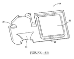
- FIG. 4 b is an outside perspective view of the housing with the housing cover installed thereon, in accordance with the present invention.
- FIG. 4 c is a perspective view of the housing with the housing cover installed thereon, in accordance with the present invention.
- FIG. 5 is a perspective inside view of an electronics cover for a mass fluid flow sensor, in accordance with the present invention.
- FIG. 6 is an outside view of an electronics cover of a mass fluid flow sensor, in accordance with the present invention.
- FIG. 7 a is a fully assembled perspective view of a mass fluid flow sensor in accordance with the present invention.
- FIG. 7 b is a cross-sectional view through the mass fluid flow sensor as indicated in FIG. 7 a in accordance with the present invention
- FIG. 8 is cross-sectional view through an automotive fluid intake manifold and further illustrated in exemplary location of the mass fluid flow sensor, in accordance with the present invention.
- FIGS. 9 a - 9 d are perspective and cross-sectional views through an alternate embodiment of a mass fluid flow sensor, in accordance with the present invention.
- FIG. 9 e is a computational fluid dynamics diagram illustrating the fluid flow direction and velocity through the mass fluid flow sensor
- FIG. 10 is a perspective view of the lead frame, in accordance with the present invention.
- FIG. 11 is a cross-sectional view of the mass fluid flow sensor having the homogeneous lead frame disposed therein, in accordance with the present invention.
- Mass fluid flow sensor 10 for calculating the amount of fluid flowing in a duct is illustrated, in accordance with the present invention.
- One application or use for sensor 10 is for measuring the amount of air inducted into an internal combustion engine (not shown).
- the present invention contemplates other uses and application for sensor 10 .
- sensor 10 may be used to calculate the amount of fluid (other than air) flowing through a duct (other than an air intake duct of an internal combustion engine).
- Mass fluid flow sensor 10 includes a housing 12 , housing cover 14 , a secondary housing cover 16 , an electronics cover 18 , and a gasket 20 .
- Housing 12 includes an integral connector 30 having connector terminals (not shown) that are in electrical communication with engine operation control electronics external to mass fluid flow sensor 10 and in electrical communication with a circuit module 32 disposed within a central housing portion 34 . Adjacent to central housing portion 34 , housing 12 further provides an integrally attached fluid sampling portion 36 . Fluid sampling portion 36 includes an inlet 38 that opens into a nozzle 39 . Nozzle 39 communicates with a substantially U-shaped flow passage 40 . U-shaped flow passage 40 terminates at an outlet 42 .
- Nozzle 39 has, generally, a jet nozzle configuration or shape. As will be further illustrated and described, nozzle 39 is defined by a generally circular opening or inlet 38 that meets longitudinally converging elliptical side surfaces (as shown in FIG. 7 b ). The longitudinally converging elliptical side surfaces of the nozzle create a relatively high pressure at an exit 41 of nozzle 39 . Further, the jet nozzle configuration of nozzle 39 creates a critical area 43 located at exit 41 having a uniform fluid flow velocity across the critical area. This critical area created by the nozzle provides enhanced fluid flow detection and measurement as will be described hereinafter. To further enhance the flow of fluid through passage 40 a wedge deflector 45 is positioned on an end of housing 12 upstream of outlet 42 .
- Wedge deflector 45 has a surface that is tilted to create an advantageously low pressure area adjacent outlet 42 . If the angle of the surface of deflector 45 (indicated by the letter ⁇ in FIG. 7 b ) is too small with respect to the direction of fluid flow an insufficient pressure drop is created at outlet 42 . Conversely, if the angle of the surface of deflector 45 is too large with respect to the direction of fluid flow an insufficient pressure drop is created at outlet 42 . Preferably, the angle ⁇ of the surface of deflector 45 is between 47° and 60° with respect to a horizontal line.
- a plurality of resistive elements are operatively disposed and supported by housing 12 and are in electrical communication with circuit module 32 via electrical conductors, such as integrally molded leads or terminals.
- the resistive elements include a hot wire element 44 , a cold wire element 46 and an internal fluid temperature (IAT) element 48 . Generally, these elements change resistance as a function of temperature.
- Circuit module 32 senses a fluid, such as, air flowing through passage 40 by monitoring the power dissipated by the elements.
- Circuit module 32 may be a single integrated circuit chip or a substrate having discrete, as well as, integrated circuits mounted thereon.
- the sensed resistance change in the elements is converted to an output signal that is received by the electronic engine control system (not shown).
- the electronic engine control system regulates the quantity of fuel injected into the engine by controlling the air to fuel ratio.
- the IAT or element 48 is generally a thermistor or similar device. Element 48 is located on housing 12 to insure an accurate reading of the temperature of the air charge during the induction cycle of the internal combustion engine. As shown in FIG. 2 , element 48 is located, preferably, external of passage 40 to minimize the fluid heating effects caused by the heat dissipation from hot element 44 .
- a fluid flow sensor 10 having elements 44 and 46 made of platinum wire wound resistors. Generally, these elements have a positive temperature coefficient. Thus, any resistive changes in the elements will correspond with a temperature change in the same direction. That is, if the temperature increases, the resistance will increase, and if the temperature decreases, the resistance will decrease.
- hot element 44 is located at exit 41 of nozzle 39 and within the critical area 43 . The location of the hot element within the critical area insures that fluid, having a uniform velocity profile, flows over the hot element causing heat to dissipate from the entire surface of the element.
- the present invention provides enhanced fluid flow detection.
- hot element 44 may for example have a resistance of 20 Ohms at 21.1° C. Thus, if the temperature increases by ⁇ 17.2° C. the resistance of the hot wire will increase by approximately 0.025 Ohms.
- the hot element 44 is used primarily for detecting the velocity of the fluid flowing through passage 40 from which the mass of fluid flowing through passage 40 may be derived.
- the cold wire element 46 may for example have a nominal resistance of 500 Ohms at 21.1° C. If the temperature of the cold wire is increase by ⁇ 17.2° C. the resistance of cold wire will increase by approximately 0.5 Ohms. The primary purpose of the cold wire element 46 is to provide temperature correction.
- circuit 500 is disposed in integrated circuit 32 , along with other control circuitry.
- Exemplary circuit 500 includes two voltage divider networks 502 and 504 in communication with an operational amplifier 506 .
- Voltage divider network 502 generally has two 500 Ohm resistors 508 and 510 which form a 50% voltage divider network and force plus pin 512 of op-amp 506 to half the output voltage on line 518 .
- the other voltage divider network 504 includes generally a 25 Ohm resistor 514 in series with the hot wire element 44 .
- the minus pin 516 of op-amp 506 is connected between resistor 514 and hot wire element 44 .
- the ratio of this network starts with a ratio of 20 Ohms to 45 Ohms, so minus pin 516 is forced to ⁇ fraction (20/45) ⁇ th of the output voltage.
- the op-amps output voltage on output line 518 will increase if the voltage on plus pin 512 is greater than the voltage on the minus pin 516 .
- the output voltage on line 518 will decrease if the voltage on plus pin 512 is less than the voltage on minus pin 516 .
- the op-amp's output voltage on line 518 will increase or decrease by a voltage amount necessary to force the voltage on plus pin 512 to equal the voltage on minus pin 516 .
- resistor network 502 provides a greater voltage on plus pin 512 that is 50% of the output voltage as compared to 44% on minus pin 516 , the op-amps output voltage will increase on line 518 .
- the power dissipated by the hot wire element 44 causes an increase in resistance of the hot element. It takes approximately one quarter watt of power in still air to increase the temperature of hot element 44 by 93.3° C. A 93.3° C. increase in temperature raises hot wire element 44 's resistance by 5 Ohms.
- the ratio of the hot wire resistance at the increased temperature to the total resistance in resistor network 504 forms a 50% voltage divider network.
- the plus and minus pins 512 and 516 of op-amp 506 are at the same voltage since both networks 502 and 504 form 50% voltage divider networks.
- the temperature of hot wire element 44 is forced to approximately 132.2° C.
- the output of the circuit on line 518 is proportional to the square root of the power removed from the hot wire times two minus 5 volts, for example.
- Nominal power dissipated by the hot wire element 44 is one-quarter of a watt which is the amount of power needed to keep the hot wire element 44 at 132.2° C. Any heat removed from the hot wire is replaced by applying more power to element 44 .
- the temperature of hot wire element 44 needs to be maintained at 200° C. above ambient temperature. If the ambient temperature is constant there is no need for temperature correction. That is, a constant difference in temperature guarantees the same amount of power will be removed from the hot wire element 44 for a given air flow.
- ambient air temperature is not constant. Typically, sensor 10 will be exposed to temperatures below freezing and above boiling. Thus, air flow temperatures lower than expected will cause a larger than desired output voltage and temperatures higher than expected will cause a lower than desired output voltage.
- the present invention provides temperature correction to compensate for the variable ambient temperature environment present in an automobile. Temperature correction is achieved through the use of the cold wire element 46 .
- the cold wire element 46 is placed in resistor network 502 in place of resistor 510 , as illustrated in FIG. 3 .
- Circuit 500 uses cold wire element 46 for temperature compensation.
- Element 46 is supported by housing 12 and is placed in the air stream outside of flow passage 40 . Placing cold wire element 46 in the air stream allows the circuit to quickly respond to changes in the ambient air temperature.
- the temperature of cold wire element 46 will follow the temperature changes of the incoming air. Since the resistance of the cold wire element (500 Ohms) is relatively large compared to the voltage drop across the element, the power dissipated is very small. For example, at 21.1° C. the resistance of element 46 is 500 Ohms with a voltage drop of 2.5 volts. Moreover, the power dissipated by element 46 is 0.0125 watts which results in a temperature increase of about ⁇ 12.2° C.
- the resistance of the cold wire element 46 would increase by 5 Ohms and resistor network 502 resistance ratio would change.
- the voltage applied to plus pins 512 would equal ⁇ fraction (505/1005) ⁇ or 50.25% of the output voltage on line 518 .
- resistor network 504 will also have to form a ratio equal to 50.25% of the output voltage.
- the hot wire resistance would need to be maintained at 25.25 Ohm to develop the same resistance ratio of 50.25% thus the hot wire element 44 will be maintained at 200° C. above the cold wire element 46 or 137.7° C. if the ambient temperature is 21.1° C.
- Cold wire element 46 is ⁇ 12.2° C. above the ambient temperature of 21.1° C.
- the circuit in FIG. 3 can dynamically adjust to ambient air temperature changes because the change in the cold wire network is directly proportional to the properties of the hot wire network.
- FIGS. 4 a and 4 b a perspective view of housing cover 14 is further illustrated, in accordance with the present invention.
- FIG. 4 a is an inside view of housing cover 14
- FIG. 4 b is an outside view of housing cover 14
- Housing cover 14 is fixedly joined to housing 12 (as shown in FIG. 4 c ) along a protruding ridge 60 and 62 .
- Ridge 60 protrudes from an inside surface 64 of housing cover 14 and matingly seals with channel 50 disposed on an inside surface 52 of housing 12 .
- Ridge 62 protruding from an inside surface 64 of housing cover 14 , matingly seals with channel 54 disposed within surface 52 and around the perimeter of flow passage 40 , thus creating an enclosed and sealed flow passage 40 .
- Housing cover 14 further includes a window aperture 66 for providing access, during manufacture, to integrated circuit 32 (as shown in FIG. 4 c ).
- window aperture 66 provides access to integrated circuit 32 during the calibration step in the manufacturing process.
- integrated circuit 32 is wire bonded using wire bonds to various terminal and/or bonding pads disposed on housing 12 .
- a channel 68 is provided around a perimeter of window 66 to matingly seal the secondary housing cover 16 to housing cover 14 .
- a side opening 70 allows air exiting flow passage 40 to flow out of both side surfaces 72 and of cover 14 .
- a ramped portion 75 is included in surface 72 to funnel and direct air passing over the surface toward cold wire element 46
- FIG. 5 A perspective inside view of secondary housing cover 16 is illustrated in FIG. 5 .
- Cover 16 includes a perimeter ridge protrusion 80 which matingly seals with housing cover 14 along the perimeter of window 66 and within channel 68 .
- Secondary housing cover 16 is substantially flat and maybe constructed of a heat conductive material, such as a metal for dissipating heat generated by integrated circuit 32 .
- secondary housing cover 16 has a generally planar outside surface 84 . After cover 16 is positioned on housing cover 14 , both the cover 14 and the secondary housing cover 16 create a longitudinally extending and generally planar surface to insure minimal disturbance of the air flowing around sensor 10 .
- FIG. 6 A perspective inside view of electronics cover 18 is illustrated in FIG. 6 .
- integrated circuit 32 is bonded to cover 18 and the resulting circuit and cover assembly is loaded into and matingly seals against housing 12 .
- Cover 18 has a protruding ridge 83 rising from a surface 85 of cover 18 .
- Protruding ridge 83 sealingly mates with a corresponding channel (not shown) disposed on housing 12 to created a weather resistant sensor housing.
- cover 18 functions as a heat sink to draw heat emanating from circuit module 32 .
- heat sink 18 is made from a metallic material or other material having similar thermal conductive properties.
- FIG. 7 a A perspective view of a fully assembled mass fluid flow sensor 10 is illustrated in FIG. 7 a , in accordance with the present invention.
- a flange 90 is integrally formed in housing 12 and includes a plurality of mounting apertures 92 and 94 . Mounting apertures 92 and 94 receive fasteners (not shown) such as screws for securing sensor 10 to a mounting surface. Further, flange 90 has a mating surface 96 for matingly engaging an engine air intake duct 304 (shown in FIG. 8 ) as will be described below.
- Gasket 20 which is configured to engage a flange ledge or shelf 98 is positioned between the engine intake duct and flange 90 to provide an air tight seal between mass fluid flow sensor 10 and air intake duct 304 .
- inlet 38 of mass fluid flow sensor 10 flows into inlet 38 of mass fluid flow sensor 10 in a direction, as indicated by arrow i, and out of outlet 42 in a direction, as indicated by arrows O.
- Inlet 38 is generally circular and as illustrated in FIG. 7 b has a generally elliptical cross-section.
- elliptical surfaces 200 which define the perimeter of inlet 38 and nozzle 39 . Moreover, as shown, elliptical surfaces 200 converge along a longitudinal axis 202 , creating an inlet and nozzle having a longitudinally converging elliptical surface.
- This inlet and nozzle configuration is known as a jet nozzle. Further, it is known that this jet nozzle configuration creates a critical area, at the exit of the nozzle, having a uniform fluid flow velocity.
- the present invention has improved accuracy as compared to the prior art because, for example, the hot element 44 is located in the critical are and therefore is evenly cooled by incoming fluid.
- an automotive vehicle has an air intake manifold 300 for supplying fresh air to the vehicle's engine (not shown).
- air intake manifold 300 includes a filter 302 for filtering the intake air and extract contaminants from the air drawn into manifold 300 .
- Air intake manifold 300 is typically attached to an air duct 304 for communicating the clean air to the vehicle's engine.
- mass fluid flow sensor 10 is positioned and fixedly secured to air duct 304 through an aperture 306 in air duct 304 .
- Outside air is drawn into intake manifold 300 in a direction indicated by arrow A and flows through manifold 300 as indicated by arrows A′ and A′′.
- air duct 304 a portion of the intake air flows into the mass air flow sensor, as indicated by arrow i, and then out of the mass fluid flow sensor as indicated by arrow o. All of the intake air eventually exits air duct 304 and enters the vehicle's engine, as indicated by arrow e.
- Electrical control signals containing information regarding the amount of air flowing through the air duct 304 , derived from measurements and processing carried out on integrated circuit 32 , is communicated to the vehicle's electronic control systems through a connector 308 and wire harness 310 .
- the present invention contemplates an assembly and/or manufacturing method or process for constructing mass fluid flow sensor 10 .
- the resistive elements are electrically connected to the housing using solder or other like material or other bonding process (i.e. resistance welding).
- the electronics cover 18 and integrated circuit 32 assembly is mounted to the housing 12 , using an adhesive or similar material.
- the housing cover 14 is mated to housing 12 and bonded thereto using an adhesive or similar material.
- the assembly is placed in an oven or other environment suitable for curing the adhesive.
- the integrated circuit 32 is wire bonded to terminals and/or bonding pads on housing 12 .
- the integrated circuit 32 is calibrated and/or adjusted and/or resistors disposed within circuit 32 are trimmed.
- the secondary housing cover 16 is mated to housing 12 and bonded thereto using an adhesive or similar material.
- sensor 10 is tested to insure proper function at different operating states and environmental conditions.
- housing 412 has a connector end 414 having electrical terminals 415 for communicating electrical signals from the mass air flow sensor to external circuitry (not shown), as illustrated in perspective view of FIG. 9 a and in the cross-sectional view of FIG. 9 b .
- Connector end 414 further has a flange 416 that enables housing 412 to be mounted to an air duct 304 of an air intake of an engine (see FIG. 8 ), for example.
- housing 412 has a central portion 418 and an air sampling end 424 .
- Central portion 419 includes an aperture 420 for receiving a circuit module 422 .
- an air sampling passage 426 is disposed.
- Air sampling passage 426 includes an inlet 428 , a sampling channel 430 , and an outlet 432 .
- Sampling channel 430 is in-molded or integrated into air sampling end 424 . More specifically, sampling channel 430 has two portions a housing portion 430 a and a housing cover portion 430 b , as shown in FIGS. 9 a and 9 c .
- the housing portion 430 a is in-molded or integrated into housing 412 and housing cover portion 430 b is in-molded or integrated into housing cover 414 . When the housing cover 414 is bonded to housing 412 the two portions, housing portion 430 a and housing cover portion 430 b mate to form a uniform tubular sampling channel 430 .
- a wedge deflector 445 is positioned on an end of housing 412 upstream of outlet 442 .
- Wedge deflector 445 has a surface that is tilted (with respect to a horizontal) to create an advantageously low pressure area adjacent outlet 432 . If the angle of the surface of deflector 445 (indicated by the letter ⁇ in FIG. 9 b ) is too small with respect to the direction of fluid flow an insufficient pressure drop is created at outlet 432 . Conversely, if the angle of the surface of deflector 445 is too large with respect to the direction of fluid flow (and horizontal line h) an insufficient pressure drop is created at outlet 432 .
- the angle ⁇ of the surface of deflector 445 is between 47° and 60° with respect to the horizontal line h.
- channel 430 includes an expansion tube portion 431 , a re-directional portion 433 and channel exit portion 435 .
- Expansion tube portion has a length l e (see FIG. 9 e ) and extends from the nozzle exit to the entrance of re-directional portion 433 .
- the re-directional portion 433 is semi-circular in shape and extends from the expansion tube portion to the channel exit portion.
- re-directional portion 433 has an inner wall having a constant inner radius r l and an outer wall having a constant outer radius r o (see FIG. 9 e ).
- the present invention provides a sampling channel 430 having reduced turbulent flow.
- Thermal sensor 434 Disposed within the fluid sampling passage 426 is a thermal sensor 434 .
- Thermal sensor 434 is in communication with circuit module 422 for detection and signal processing of electrical signals indicative of a change in power dissipation of thermal sensor 434 . Processed and/or conditioned signals are then communicated through an electrical lead frame to terminals 415 for communication to external circuitry.
- Inlet 428 of fluid sampling passage 426 is configured to have elliptically converging interior surfaces 436 that define a jet nozzle 437 , as shown in FIG. 9 b .
- Thermal sensor 434 is positioned at an exit 438 of jet nozzle 437 .
- channel 430 of fluid sampling passage 426 is preferably tubular in shape.
- the jet nozzle exit 438 has a diameter e that is less than a diameter t of tubular channel 430 , as shown in the partial-expanded view of fluid sampling end 424 of FIG. 9 d .
- the different diameters of jet nozzle exit 438 and tubular channel 430 create a transitional section 460 at the interface of nozzle exit 438 and channel 430 .
- a fully annular vortices is created in transitional section 460 .
- Such a controlled fully annular vortices spins within transitional section 460 creating a fluid bearing 502 which extends circumferentially around the nozzle exit 438 (see FIG. 9 e ).
- Fluid bearing 502 creates a substantially frictionless area at transitional section 460 that promotes (enhances) fluid flow through sampling channel 430 .
- channel 430 includes expansion tube portion 431 having an expansion tube length l e .
- the expansion tube has generally straight walls and runs between nozzle exit 438 and an entrance 514 of re-directional portion 433 of channel 430 .
- the length of the expansion tube is predetermined such that at a maximum fluid flow velocity the fluid contacts or “attaches” to a wall 510 of the expansion tube before reaching an end 512 of expansion tube 431 .
- the Fluid bearing 502 creates a low pressure at nozzle exit 438 .
- fluid is pulled through the nozzle and into the sampling channel 430 to wall 510 of the channel and prevents fluid from re-circulating backward in the channel. Therefore, the present invention has many benefits over the prior art.
- the present invention has increased dynamic range, such that the mass fluid flow may be determined at very low fluid intake speeds as well as at very high fluid intake speed.
- Lead frame 600 for communicating electrical signals to and from electronic components mounted within the mass fluid flow sensor to electronic components mounted exterior of the sensor is illustrated, in accordance with the present invention.
- Lead frame 600 includes a connector pin portion 602 and an electrical device attachment portion 604 .
- Connector pins 602 cooperate with a housing connector end portion 605 to form a male side of an electrical connector.
- portion 605 will cooperate with a female connector end portion and connector pins 606 will be inserted into the female connector end portion (not shown) as well known in the art.
- Attachment portion 604 includes electrical contact tabs or pads 608 for connecting electrical devices such as integrated circuits and resistors, to lead frame 600 .
- lead frame 600 is held together prior to assembly into a sensor housing by lead frame stabilizing bars 610 .
- housing lead frame 600 is placed in a sensor housing mold (not shown) where an insert molding process is performed. After the housing has cured stabilizing bars 610 are severed creating distinct electrical paths.
- FIG. 11 a cross-sectional view of a sensor housing 650 is illustrated having lead frame 600 insert molded therein, in accordance with the present invention.
- Connector pins 606 disposed in male connector end 652 electrically couple to a female connector end (not shown) in a conventional manner.
- One significant problem overcome by the present invention is the bending or damage to connector pins 606 during the insertion of connector end portion 605 into a female connector portion.
- the present invention provides a lead frame 600 made from a homogenous material having superior structural and corrosion resistance properties.
- lead frame 600 is preferably made of stainless steel or similar material. Stainless steel provides enhanced structural stability to the connector pins 606 .
- a stainless steel lead frame 600 eliminates corrosion of the lead frame especially at the electrical attachment portions of the lead frame 608 that are exposed to corrosive environments.
- lead frame 600 of the present invention is configured to provide increased overall housing structural stability.
- a portion of lead frame 600 includes conductors 612 and 614 that extend longitudinally along the length of housing 650 .
- This configuration provides increased structural stability along a longitudinal axis of housing 650 .
- housing 650 of the present invention can withstand harsher environments where the housing is exposed to high acceleration or vibration fields.
- lead frame 600 may be used in other types of sensors and electronic modules.
- the lead frame 600 of the present invention is especially useful in sensors and electronic modules that are exposed to harsh and corrosive environments, such as an automotive environment where the sensor or electronic module is mounted to an exterior of a vehicle or within a vehicle engine compartment.
Abstract
Description
Claims (27)
Priority Applications (4)
| Application Number | Priority Date | Filing Date | Title |
|---|---|---|---|
| US10/269,232 US6845661B2 (en) | 2002-10-11 | 2002-10-11 | Lead frame for automotive electronics |
| JP2003106380A JP2004132351A (en) | 2002-10-11 | 2003-04-10 | Leadframes of electric parts for automobile electronics |
| GB0309437A GB2394057A (en) | 2002-10-11 | 2003-04-25 | Device for detecting the mass of a flowing fluid |
| DE10347912A DE10347912B4 (en) | 2002-10-11 | 2003-10-10 | Improved lead frame for automotive electronic circuits |
Applications Claiming Priority (1)
| Application Number | Priority Date | Filing Date | Title |
|---|---|---|---|
| US10/269,232 US6845661B2 (en) | 2002-10-11 | 2002-10-11 | Lead frame for automotive electronics |
Publications (2)
| Publication Number | Publication Date |
|---|---|
| US20040069060A1 US20040069060A1 (en) | 2004-04-15 |
| US6845661B2 true US6845661B2 (en) | 2005-01-25 |
Family
ID=32030377
Family Applications (1)
| Application Number | Title | Priority Date | Filing Date |
|---|---|---|---|
| US10/269,232 Expired - Fee Related US6845661B2 (en) | 2002-10-11 | 2002-10-11 | Lead frame for automotive electronics |
Country Status (4)
| Country | Link |
|---|---|
| US (1) | US6845661B2 (en) |
| JP (1) | JP2004132351A (en) |
| DE (1) | DE10347912B4 (en) |
| GB (1) | GB2394057A (en) |
Cited By (4)
| Publication number | Priority date | Publication date | Assignee | Title |
|---|---|---|---|---|
| US20110000289A1 (en) * | 2006-09-27 | 2011-01-06 | Uwe Konzelmann | Plug-in sensor having an optimized flow outlet |
| US20120160024A1 (en) * | 2010-12-28 | 2012-06-28 | Hitachi Automotive Systems, Ltd. | Intake temperature sensor |
| US20130118242A1 (en) * | 2011-11-14 | 2013-05-16 | Denso Corporation | Air flow measuring device and method of making housing for the device |
| US20140060176A1 (en) * | 2011-03-18 | 2014-03-06 | Torsten Mais | Device for detecting at least one property of a fluid medium |
Families Citing this family (6)
| Publication number | Priority date | Publication date | Assignee | Title |
|---|---|---|---|---|
| JP5496027B2 (en) * | 2010-09-09 | 2014-05-21 | 日立オートモティブシステムズ株式会社 | Thermal air flow meter |
| JP2013024710A (en) * | 2011-07-20 | 2013-02-04 | Denso Corp | Air flow measurement device |
| JP5743922B2 (en) * | 2012-02-21 | 2015-07-01 | 日立オートモティブシステムズ株式会社 | Thermal air flow measurement device |
| DE102015102453A1 (en) * | 2015-02-20 | 2016-08-25 | Heraeus Deutschland GmbH & Co. KG | Ribbon-shaped substrate for the production of chip card modules, chip card module, electronic device with such a chip card module and method for producing a substrate |
| GB2617625A (en) * | 2017-10-30 | 2023-10-18 | Zehnder Group Uk Ltd | Air flow sensor |
| GB2568041B (en) * | 2017-10-30 | 2022-11-30 | Zehnder Group Uk Ltd | Air flow sensor |
Citations (13)
| Publication number | Priority date | Publication date | Assignee | Title |
|---|---|---|---|---|
| JPS60230020A (en) * | 1984-04-28 | 1985-11-15 | Toyota Motor Corp | Thermal resistance type flow rate detecting device |
| US4641418A (en) * | 1982-08-30 | 1987-02-10 | International Rectifier Corporation | Molding process for semiconductor devices and lead frame structure therefor |
| EP0313089A2 (en) | 1987-10-23 | 1989-04-26 | Hitachi, Ltd. | Hot wire type of air flow meter and internal combustion engine using the same |
| EP0323694A2 (en) | 1987-10-09 | 1989-07-12 | Hitachi, Ltd. | Thermal air flow meter |
| US4911008A (en) * | 1988-10-03 | 1990-03-27 | Allied-Signal Inc. | Hot film anemometer |
| EP0735349A1 (en) | 1995-03-28 | 1996-10-02 | Ford Motor Company | Mass air flow sensor housing |
| GB2316750A (en) | 1996-09-02 | 1998-03-04 | Hitachi Ltd | Heating resistor type air flow meter |
| US5756893A (en) * | 1995-06-14 | 1998-05-26 | Nippondenso Co., Ltd. | Thermal flow meter |
| US6182639B1 (en) | 1997-06-26 | 2001-02-06 | Hitachi, Ltd. | Thermal-type airflow meter, intake air system for an internal combustion engine, and control system for the same |
| US6185998B1 (en) | 1997-05-28 | 2001-02-13 | Mitsubishi Denki Kabushiki Kaisha | Heat sensitive flow amount sensor and inlet system of internal combustion engine |
| US6240775B1 (en) * | 1998-05-11 | 2001-06-05 | Mitsubishi Denki Kabushiki Kaisha | Flow rate sensor |
| US6336361B1 (en) * | 1999-06-08 | 2002-01-08 | Mitsubishi Denki Kabushiki Kaisha | Flow rate sensor with symmetrical support protective member and structural member |
| US20020078744A1 (en) | 2000-12-21 | 2002-06-27 | Gehman Richard William | system for sensing the motion or pressure of a fluid |
-
2002
- 2002-10-11 US US10/269,232 patent/US6845661B2/en not_active Expired - Fee Related
-
2003
- 2003-04-10 JP JP2003106380A patent/JP2004132351A/en active Pending
- 2003-04-25 GB GB0309437A patent/GB2394057A/en not_active Withdrawn
- 2003-10-10 DE DE10347912A patent/DE10347912B4/en not_active Expired - Fee Related
Patent Citations (14)
| Publication number | Priority date | Publication date | Assignee | Title |
|---|---|---|---|---|
| US4641418A (en) * | 1982-08-30 | 1987-02-10 | International Rectifier Corporation | Molding process for semiconductor devices and lead frame structure therefor |
| JPS60230020A (en) * | 1984-04-28 | 1985-11-15 | Toyota Motor Corp | Thermal resistance type flow rate detecting device |
| EP0323694A2 (en) | 1987-10-09 | 1989-07-12 | Hitachi, Ltd. | Thermal air flow meter |
| EP0313089A2 (en) | 1987-10-23 | 1989-04-26 | Hitachi, Ltd. | Hot wire type of air flow meter and internal combustion engine using the same |
| US4911008A (en) * | 1988-10-03 | 1990-03-27 | Allied-Signal Inc. | Hot film anemometer |
| US5563340A (en) * | 1995-03-28 | 1996-10-08 | Ford Motor Company | Mass air flow sensor housing |
| EP0735349A1 (en) | 1995-03-28 | 1996-10-02 | Ford Motor Company | Mass air flow sensor housing |
| US5756893A (en) * | 1995-06-14 | 1998-05-26 | Nippondenso Co., Ltd. | Thermal flow meter |
| GB2316750A (en) | 1996-09-02 | 1998-03-04 | Hitachi Ltd | Heating resistor type air flow meter |
| US6185998B1 (en) | 1997-05-28 | 2001-02-13 | Mitsubishi Denki Kabushiki Kaisha | Heat sensitive flow amount sensor and inlet system of internal combustion engine |
| US6182639B1 (en) | 1997-06-26 | 2001-02-06 | Hitachi, Ltd. | Thermal-type airflow meter, intake air system for an internal combustion engine, and control system for the same |
| US6240775B1 (en) * | 1998-05-11 | 2001-06-05 | Mitsubishi Denki Kabushiki Kaisha | Flow rate sensor |
| US6336361B1 (en) * | 1999-06-08 | 2002-01-08 | Mitsubishi Denki Kabushiki Kaisha | Flow rate sensor with symmetrical support protective member and structural member |
| US20020078744A1 (en) | 2000-12-21 | 2002-06-27 | Gehman Richard William | system for sensing the motion or pressure of a fluid |
Cited By (8)
| Publication number | Priority date | Publication date | Assignee | Title |
|---|---|---|---|---|
| US20110000289A1 (en) * | 2006-09-27 | 2011-01-06 | Uwe Konzelmann | Plug-in sensor having an optimized flow outlet |
| US8418548B2 (en) * | 2006-09-27 | 2013-04-16 | Robert Bosch Gmbh | Plug-in sensor having an optimized flow outlet |
| US20120160024A1 (en) * | 2010-12-28 | 2012-06-28 | Hitachi Automotive Systems, Ltd. | Intake temperature sensor |
| US8813556B2 (en) * | 2010-12-28 | 2014-08-26 | Hitachi Automotive Systems, Ltd. | Intake temperature sensor |
| US20140060176A1 (en) * | 2011-03-18 | 2014-03-06 | Torsten Mais | Device for detecting at least one property of a fluid medium |
| US9618373B2 (en) * | 2011-03-18 | 2017-04-11 | Robert Bosch Gmbh | Device for detecting at least one property of a fluid medium |
| US20130118242A1 (en) * | 2011-11-14 | 2013-05-16 | Denso Corporation | Air flow measuring device and method of making housing for the device |
| US8714000B2 (en) * | 2011-11-14 | 2014-05-06 | Denso Corporation | Air flow measuring device and method of making housing for the device |
Also Published As
| Publication number | Publication date |
|---|---|
| DE10347912B4 (en) | 2005-08-11 |
| GB2394057A (en) | 2004-04-14 |
| US20040069060A1 (en) | 2004-04-15 |
| DE10347912A1 (en) | 2004-04-22 |
| JP2004132351A (en) | 2004-04-30 |
Similar Documents
| Publication | Publication Date | Title |
|---|---|---|
| US6708561B2 (en) | Fluid flow meter having an improved sampling channel | |
| US6336361B1 (en) | Flow rate sensor with symmetrical support protective member and structural member | |
| US6622555B2 (en) | Fluid flow meter | |
| US6619140B2 (en) | Fluid flow meter having thermal flow sensor disposed in one of a plurality of fluid passages | |
| US6826955B2 (en) | Mass fluid flow sensor having an improved housing design | |
| US6223594B1 (en) | Thermal type air flow amount measuring apparatus having flow rectifier | |
| US6845661B2 (en) | Lead frame for automotive electronics | |
| US9328686B2 (en) | Flow measuring device | |
| US20030019289A1 (en) | Air flow meter | |
| US10989128B2 (en) | Intake air flow rate measuring device | |
| US5847275A (en) | Temperature detecting apparatus and thermal type flow meter using the same | |
| US7258002B2 (en) | Fluid flow detecting apparatus | |
| JP6032140B2 (en) | Flow measuring device | |
| US10551233B2 (en) | Air flow rate measurement device | |
| US6952961B2 (en) | Air flow rate measuring device | |
| US7047805B2 (en) | Fluid flow meter having an auxiliary flow passage | |
| WO2002103301A1 (en) | Heating resistor flow rate measuring instrument | |
| JP2001124606A (en) | Heating resistance element type air flow measuring instrument | |
| JP3070642B2 (en) | Flowmeter | |
| JPH11132810A (en) | Air flowmeter and adjustment thereof |
Legal Events
| Date | Code | Title | Description |
|---|---|---|---|
| AS | Assignment |
Owner name: VISTEON GLOBAL TECHNOLOGIES, INC., MICHIGAN Free format text: ASSIGNMENT OF ASSIGNORS INTEREST;ASSIGNORS:BOGDANOV, LEON;ROSS, RALPH J.;CARON, RICHARD W.;AND OTHERS;REEL/FRAME:013809/0509 Effective date: 20030224 |
|
| CC | Certificate of correction | ||
| AS | Assignment |
Owner name: JPMORGAN CHASE BANK, N.A., AS ADMINISTRATIVE AGENT Free format text: SECURITY AGREEMENT;ASSIGNOR:VISTEON GLOBAL TECHNOLOGIES, INC.;REEL/FRAME:020497/0733 Effective date: 20060613 |
|
| REMI | Maintenance fee reminder mailed | ||
| LAPS | Lapse for failure to pay maintenance fees | ||
| STCH | Information on status: patent discontinuation |
Free format text: PATENT EXPIRED DUE TO NONPAYMENT OF MAINTENANCE FEES UNDER 37 CFR 1.362 |
|
| AS | Assignment |
Owner name: JPMORGAN CHASE BANK, TEXAS Free format text: SECURITY INTEREST;ASSIGNOR:VISTEON GLOBAL TECHNOLOGIES, INC.;REEL/FRAME:022368/0001 Effective date: 20060814 Owner name: JPMORGAN CHASE BANK,TEXAS Free format text: SECURITY INTEREST;ASSIGNOR:VISTEON GLOBAL TECHNOLOGIES, INC.;REEL/FRAME:022368/0001 Effective date: 20060814 |
|
| FP | Expired due to failure to pay maintenance fee |
Effective date: 20090125 |
|
| AS | Assignment |
Owner name: WILMINGTON TRUST FSB, AS ADMINISTRATIVE AGENT, MIN Free format text: ASSIGNMENT OF SECURITY INTEREST IN PATENTS;ASSIGNOR:JPMORGAN CHASE BANK, N.A., AS ADMINISTRATIVE AGENT;REEL/FRAME:022575/0186 Effective date: 20090415 Owner name: WILMINGTON TRUST FSB, AS ADMINISTRATIVE AGENT,MINN Free format text: ASSIGNMENT OF SECURITY INTEREST IN PATENTS;ASSIGNOR:JPMORGAN CHASE BANK, N.A., AS ADMINISTRATIVE AGENT;REEL/FRAME:022575/0186 Effective date: 20090415 |
|
| AS | Assignment |
Owner name: VISTEON GLOBAL TECHNOLOGIES, INC., MICHIGAN Free format text: RELEASE BY SECURED PARTY AGAINST SECURITY INTEREST IN PATENTS RECORDED AT REEL 022575 FRAME 0186;ASSIGNOR:WILMINGTON TRUST FSB, AS ADMINISTRATIVE AGENT;REEL/FRAME:025105/0201 Effective date: 20101001 |