EP2857182A2 - Verfahren zur herstellung eines stellenweise verstärkten dichtungsstrangs - Google Patents
Verfahren zur herstellung eines stellenweise verstärkten dichtungsstrangs Download PDFInfo
- Publication number
- EP2857182A2 EP2857182A2 EP20140003175 EP14003175A EP2857182A2 EP 2857182 A2 EP2857182 A2 EP 2857182A2 EP 20140003175 EP20140003175 EP 20140003175 EP 14003175 A EP14003175 A EP 14003175A EP 2857182 A2 EP2857182 A2 EP 2857182A2
- Authority
- EP
- European Patent Office
- Prior art keywords
- cavity
- flowable material
- sealing strip
- wall
- strand
- Prior art date
- Legal status (The legal status is an assumption and is not a legal conclusion. Google has not performed a legal analysis and makes no representation as to the accuracy of the status listed.)
- Granted
Links
Images

Classifications
-
- B—PERFORMING OPERATIONS; TRANSPORTING
- B29—WORKING OF PLASTICS; WORKING OF SUBSTANCES IN A PLASTIC STATE IN GENERAL
- B29C—SHAPING OR JOINING OF PLASTICS; SHAPING OF MATERIAL IN A PLASTIC STATE, NOT OTHERWISE PROVIDED FOR; AFTER-TREATMENT OF THE SHAPED PRODUCTS, e.g. REPAIRING
- B29C70/00—Shaping composites, i.e. plastics material comprising reinforcements, fillers or preformed parts, e.g. inserts
- B29C70/68—Shaping composites, i.e. plastics material comprising reinforcements, fillers or preformed parts, e.g. inserts by incorporating or moulding on preformed parts, e.g. inserts or layers, e.g. foam blocks
- B29C70/74—Moulding material on a relatively small portion of the preformed part, e.g. outsert moulding
- B29C70/745—Filling cavities in the preformed part
-
- B—PERFORMING OPERATIONS; TRANSPORTING
- B60—VEHICLES IN GENERAL
- B60J—WINDOWS, WINDSCREENS, NON-FIXED ROOFS, DOORS, OR SIMILAR DEVICES FOR VEHICLES; REMOVABLE EXTERNAL PROTECTIVE COVERINGS SPECIALLY ADAPTED FOR VEHICLES
- B60J10/00—Sealing arrangements
- B60J10/15—Sealing arrangements characterised by the material
- B60J10/18—Sealing arrangements characterised by the material provided with reinforcements or inserts
-
- B—PERFORMING OPERATIONS; TRANSPORTING
- B60—VEHICLES IN GENERAL
- B60J—WINDOWS, WINDSCREENS, NON-FIXED ROOFS, DOORS, OR SIMILAR DEVICES FOR VEHICLES; REMOVABLE EXTERNAL PROTECTIVE COVERINGS SPECIALLY ADAPTED FOR VEHICLES
- B60J10/00—Sealing arrangements
- B60J10/20—Sealing arrangements characterised by the shape
- B60J10/24—Sealing arrangements characterised by the shape having tubular parts
Definitions
- the invention relates to a method for producing a locally reinforced, tubular extruded with a cavity sealing strip, wherein at least one predetermined longitudinal position of the sealing strip in the cavity, a sealing strand reinforcing material is introduced.
- Partially reinforced sealing strands are required in particular for the formation of seals on vehicle doors, door frames, body flaps or the like.
- sealing strips extruded tubularly with a cavity and cut to a specific length are reinforced in places by inserts of elastomeric material.
- the inserts are e.g. by means of rods which are provided with a length scale, or rods of known length inserted into the cavity and brought to the intended longitudinal position.
- This longitudinal position corresponds to a position particularly stressed in the installed state of the sealing strip, e.g. a bend counteracted by the enhancement of undesirable deformation or a location which for some reason requires a local increase in the stiffness of the seal.
- the present invention provides a new method for producing a locally reinforced sealing strip of the type mentioned, which is characterized in that the reinforcing material is introduced as a flowable, solidifying in the cavity to an elastically deformable material material.
- the flowable material may be directed through an opening of the cavity at a strand end to the longitudinal position or may be introduced through the wall of the cavity into the cavity.
- the introduction of the flowable material through the opening at the end of the strand can be done by means of a rod longitudinally inserted into the cavity pipe lance.
- the flowable material For introducing the flowable material through the wall of the cavity through an opening formed in the cavity wall can be used.
- the introduction of flowable material by means of a piercing hole generating injection cannula takes place.
- the injection cannula beveled at the opening leaves only one puncture slot.
- the solidified material may be fixed in the cavity by adhesion to and / or positive engagement with the cavity wall in the longitudinal direction of the strand to prevent the formed reinforcement from slipping within the seal.
- periodically recurring projections are expediently formed in the cavity, preferably by variable extrusion of the sealing strip.
- the flowable material fills the cavity in cross-section only partially to achieve a desired deformation and / or reinforcement behavior.
- a dividing wall dividing the cavity in the transverse direction of the strand can be formed, and the flowable material can only be introduced into a partial space.
- the sealant strand is rotated about its longitudinal axis to form a tubular lining of the cavity by the flowable or solidified material. Turning 360 ° results in a tubular inner lining.
- the sealing strip can also be suitably processed by pinching.
- a rubber-modified polyester or polyether is preferably introduced.
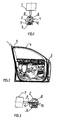
- FIG. 1 An in Fig. 1 shown in cross-section sealing strip 1 with a tubular sealing portion 2 and a mounting portion 3 serves to form a seal 4, which at an in Fig. 2 reveals the illustrated vehicle door.
- the sealing strip 1 forming the seal 4 is reinforced at predetermined locations before or after the connection with the door 5, in the example shown via a double-adhesive tape 6.
- a flowable Material 10 introduced into the cavity 8 of the tubular sealing portion 1 is a flowable Material 10 introduced.
- the flowable material 10 in the example shown is a rubber modified polyether or polyester which solidifies in the cavity 8 to a foamed, elastically deformable material.
- the injection cannula 9 which is bevelled at the opening, leaves behind a barely visible puncture slot, which could also be formed at a blind spot of the seal.
- the introduction of the flowable material into the cavity 8 could also be introduced through a prefabricated opening 11 in the wall of the tubular sealing portion 2.
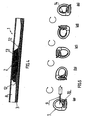
- Fig. 4 Sectionally illustrated in a longitudinal section sealing strip 1 has protruding into the interior of the cavity 8, periodically recurring projections 12, which ensure that a formed by the flowable material 10 reinforcement 13 is locked in the longitudinal direction of the sealing strip and thus can not slip.
- a locking by adhesion of the solidifying material may be given to the inner wall of the cavity 8.
- Fig. 5 shows how can be formed by rotation of the sealing strip 1 about its longitudinal axis by 360 ° of flowable injected material 10 as reinforcement a tubular inner lining 14.
- FIG. 6 Another way to specifically arrange reinforcing material 10 in a cavity, shows Fig. 6 , The cavity 8 is divided transversely to the strand longitudinal direction by a partition wall 15.
- Fig. 7 shows the introduction of flowable material through an end opening 16 of the sealing strip 1 therethrough.
- a flowable material conductive lance 17 is inserted through the opening 16 in the longitudinal direction of the strand until the end of the lance has reached the predetermined, to be provided with a reinforcement point. To determine this point, the lance 17 is provided with a length scale 18, for example. End stops would also be considered.
Landscapes
- Engineering & Computer Science (AREA)
- Mechanical Engineering (AREA)
- Chemical & Material Sciences (AREA)
- Composite Materials (AREA)
- Seal Device For Vehicle (AREA)
- Extrusion Moulding Of Plastics Or The Like (AREA)
- Gasket Seals (AREA)
Abstract
Description
- Die Erfindung betrifft ein Verfahren zur Herstellung eines stellenweise verstärkten, schlauchartig mit einem Hohlraum extrudierten Dichtungsstrangs, wobei an wenigstens einer vorbestimmten Längsposition des Dichtungsstrangs in den Hohlraum ein den Dichtungsstrang verstärkendes Material eingebracht wird. Stellenweise verstärkte Dichtungsstränge werden insbesondere zur Bildung von Dichtungen an Fahrzeugtüren, Türeinfassungen, Karosserieklappen oder dergleichen benötigt.
- In einem durch Benutzung bekannten solchen Verfahren werden schlauchartig mit einem Hohlraum extrudierte und auf eine bestimmte Länge zugeschnittene Dichtungsstränge stellenweise durch Einsatzstücke aus Elastomermaterial verstärkt. Die Einsatzstücke werden z.B. mit Hilfe von Stäben, die mit einer Längenskala versehen sind, oder Stäben bekannter Länge in den Hohlraum eingeschoben und an die vorgesehene Längsposition gebracht. Diese Längsposition entspricht einer im verbauten Zustand des Dichtungsstrangs besonders beanspruchten Stelle, z.B. einer Biegung, an welcher durch die Verstärkung einer unerwünschten Verformung entgegengewirkt wird oder einer Stelle, die aus irgendeinem Grund eine lokale Erhöhung der Steifigkeit der Dichtung erfordert.
- Durch die vorliegende Erfindung wird ein neues Verfahren zur Herstellung eines stellenweise verstärkten Dichtungsstrangs der eingangs erwähnten Art geschaffen, das dadurch gekennzeichnet ist, dass das verstärkende Material als fließfähiges, sich in dem Hohlraum zu einem elastisch verformbaren Material verfestigendes Material eingebracht wird.
- Vorteilhaft ergibt sich nach diesem Verfahren für die Herstellung lokaler Verstärkungen ein verringerter Arbeitsaufwand.
- Das fließfähige Material kann durch eine Öffnung des Hohlraums an einem Strangende hindurch zu der Längsposition geleitet oder durch die Wand des Hohlraums hindurch in den Hohlraum eingebracht werden.
- Die Einbringung des fließfähigen Materials durch die Öffnung am Strangende hindurch kann mit Hilfe einer in Stranglängsrichtung in den Hohlraum eingeschobenen Leitungslanze erfolgen.
- Zum Einbringen des fließfähigen Materials durch die Wand des Hohlraums hindurch kann eine in der Hohlraumwand gebildete Öffnung genutzt werden. Alternativ erfolgt die Einbringung von fließfähigem Material mit Hilfe einer ein Einstichloch erzeugenden Injektionskanüle. Zweckmäßig hinterlässt die an der Öffnung abgeschrägte Injektionskanüle nur einen Einstichschlitz.
- Das verfestigte Material kann in dem Hohlraum durch Anhaften an oder/und Formschluss mit der Hohlraumwand in Stranglängsrichtung fixiert werden, um zu verhindern, dass die gebildete Verstärkung innerhalb der Dichtung verrutscht. Zur formschlüssigen Fixierung werden zweckmäßig in den Hohlraum vorstehende, periodisch wiederkehrende Vorsprünge gebildet, vorzugsweise durch variable Extrusion des Dichtungsstrangs.
- In einer Ausführung des Verfahrens füllt das fließfähige Material den Hohlraum im Querschnitt nur zum Teil aus, um ein gewünschtes Verformungs- oder/und Verstärkungsverhalten zu erzielen.
- Zur teilweisen Ausfüllung kann eine den Hohlraum in Strangquerrichtung unterteilende Trennwand gebildet und das fließfähige Material nur in einen Teilraum eingebracht werden.
- In einer weiteren Ausführungsform wird der Dichtungsstrang unter Bildung einer rohrförmigen Auskleidung des Hohlraums durch das fließfähige bzw. verfestigte Material um seine Längsachse gedreht. Bei Drehung um 360° ergibt sich eine schlauchförmige Innenauskleidung.
- Zur gezielten Formung des eingebrachten Materials kann der Dichtungsstrang auch geeignet durch Quetschung bearbeitet werden.
- Als fließfähiges Material wird vorzugsweise ein mit Kautschuk modifizierter Polyester oder Polyether eingebracht.
- Zweckmäßig sorgt man für eine Verfestigung des fließfähigen Materials zu einem geschäumten Material.
- Die Erfindung wird nachfolgend unter Bezug auf die beiliegenden, verschiedene Ausführungsformen des Verfahrens beschreibende Zeichnungen weiter erläutert. Es zeigen:
- Fig. 1
- die Bildung einer lokalen Verstärkung durch Injektion,
- Fig. 2
- die Bildung einer lokalen Verstärkung an einem eingebauten Dichtungsstrang,
- Fig. 3
- die Einbringung von fließfähigem Material in einen Dichtungshohlraum durch eine vorgefertigte Öffnung hindurch,
- Fig. 4
- eine die Fixierung der Verstärkung innerhalb eines Hohlraums erläuternde Darstellung,
- Fig. 5
- eine die Bildung einer schlauchförmigen Innenauskleidung als Verstärkung erläuternden Darstellung,
- Fig. 6
- die Injizierung von fließfähigem Material in einen Dichtungsstrang mit in Querrichtung unterteiltem Hohlraum, und
- Fig. 7
- eine die Einbringung von fließfähigem Material in einen Hohlraum einer Dichtung durch eine Endöffnung hindurch erläuternde Darstellung.
- Ein in
Fig. 1 im Querschnitt gezeigter Dichtungsstrang 1 mit einem schlauchförmigen Dichtungsabschnitt 2 und einem Befestigungsabschnitt 3 dient zur Bildung einer Dichtung 4, die an einer inFig. 2 dargestellten Fahrzeugtür umläuft. - Der die Dichtung 4 bildende Dichtungsstrang 1 wird, vor oder nach der Verbindung mit der Tür 5, in dem gezeigten Beispiel über ein doppeltklebendes Klebeband 6, an vorbestimmten Stellen verstärkt.
- Mit Hilfe einer Injektionsvorrichtung 7, die mit einer Injektionskanüle 9 versehen ist, wird in den Hohlraum 8 des schlauchförmigen Dichtungsabschnitts 1 ein fließfähiges Material 10 eingebracht. Bei dem fließfähigen Material 10 handelt es sich in dem gezeigten Beispiel um ein mit Kautschuk modifiziertes Polyether oder Polyester, das sich in dem Hohlraum 8 zu einem geschäumten, elastisch verformbaren Material verfestigt.
- Als zu verstärkende Stellen kommen z.B. Biegungen in Betracht, an denen sich der Dichtungsstrang ohne Verstärkung in unerwünschter Weise verformen würde. Darüber hinaus können bestimmte Stellen der Dichtung eines erhöhten Anpresswiderstand erfordern.
- Die an der Öffnung abgeschrägte Injektionskanüle 9 hinterlässt einen kaum sichtbaren Einstechschlitz, der zudem an einer uneinsehbaren Stelle der Dichtung gebildet sein könnte.
- Wie
Fig. 3 zeigt, ließe sich das Einbringen des fließfähigen Materials in den Hohlraum 8 auch durch eine vorgefertigte Öffnung 11 in der Wand des schlauchförmigen Dichtungsabschnitts 2 hindurch einbringen. - Der in
Fig. 4 abschnittsweise in einem Längsschnitt dargestellte Dichtungsstrang 1 weist ins Innere des Hohlraums 8 vorstehende, periodisch wiederkehrende Vorsprünge 12 auf, die dafür sorgen, dass eine durch das fließfähige Material 10 gebildete Verstärkung 13 in Längsrichtung des Dichtungsstrangs arretiert ist und somit nicht verrutschen kann. Statt durch einen solchen Formschluss kann natürlich auch eine Arretierung durch Anhaften des sich verfestigenden Materials an der Innenwand des Hohlraums 8 gegeben sein. - Das fließfähige Material 10 bzw. die daraus gebildete Verstärkung braucht nicht wie die Verstärkung 13 den Hohlraum 8 im Querschnitt vollständig auszufüllen.
Fig. 5 zeigt, wie durch Drehung des Dichtungsstrangs 1 um seine Längsachse um 360° aus fließfähigem injizierten Material 10 als Verstärkung eine schlauchförmige Innenauskleidung 14 gebildet werden kann. - Eine weitere Möglichkeit, in einem Hohlraum gezielt Verstärkungsmaterial 10 anzuordnen, zeigt
Fig. 6 . Der Hohlraum 8 ist quer zur Stranglängsrichtung durch eine Trennwand 15 unterteilt. -
Fig. 7 zeigt die Einbringung von fließfähigem Material durch eine Endöffnung 16 des Dichtungsstrangs 1 hindurch. Eine fließfähiges Material leitende Lanze 17 wird durch die Öffnung 16 hindurch in Stranglängsrichtung eingeschoben, bis das Ende der Lanze die vorbestimmte, mit einer Verstärkung zu versehende Stelle erreicht hat. Zur Bestimmung dieser Stelle ist die Lanze 17 z.B. mit einer Längenskala 18 versehen. In Betracht kämen auch Endanschläge.
Claims (12)
- Verfahren zur Herstellung eines stellenweise verstärkten, schlauchartig mit einem Hohlraum (8) extrudierten Dichtungsstrangs (1), wobei an wenigstens einer vorbestimmten Längsposition des Dichtungsstrangs (1) in den Hohlraum (8) ein den Dichtungsstrang (1) verstärkendes Material eingebracht wird,
dadurch gekennzeichnet,
dass das verstärkende Material als fließfähiges, sich in dem Hohlraum zu einem elastisch verformbaren Material (13,14) verfestigendes Material (10) eingebracht wird. - Verfahren nach Anspruch 1,
dadurch gekennzeichnet,
dass das fließfähige Material (10) durch eine Öffnung (16) des Hohlraums (8) an einem Strangende hindurch zu der Längsposition geleitet oder durch die Wand des Hohlraums (8) hindurch in den Hohlraum (8) eingebracht wird. - Verfahren nach Anspruch 2,
dadurch gekennzeichnet,
dass das fließfähige Material (10) durch die Öffnung (16) am Strangende hindurch mit Hilfe einer in Stranglängsrichtung in den Hohlraum (8) eingeschobenen Leitungslanze (17) eingebracht wird. - Verfahren nach Anspruch 2,
dadurch gekennzeichnet,
dass das fließfähige Material (10) in den Hohlraum (8) durch eine Öffnung (11) in der Hohlraumwand hindurch oder mit Hilfe einer in der Hohlraumwand ein Einstichloch erzeugenden Injektionskanüle (9) eingebracht wird. - Verfahren nach einem der Ansprüche 1 bis 4,
dadurch gekennzeichnet,
dass das verfestigte Material (10) in den Hohlraum (8) durch Anhaften an oder/und Formschluss mit der Hohlraumwand in Stranglängsrichtung fixiert wird. - Verfahren nach einem der Ansprüche 1 bis 5,
dadurch gekennzeichnet,
dass der Hohlraum (8) im Querschnitt durch das fließfähige Material (10) nur zum Teil gefüllt wird. - Verfahren nach Anspruch 6,
dadurch gekennzeichnet,
dass der Hohlraum (8) im Querschnitt durch eine Trennwand (15) unterteilt wird. - Verfahren nach Anspruch 6 oder 7,
dadurch gekennzeichnet,
dass der Dichtungsstrang (1) unter Bildung einer rohrförmigen Auskleidung (14) des Hohlraums (8) durch das fließfähige Material (10) um seine Längsachse gedreht wird. - Verfahren nach einem der Ansprüche 1 bis 8,
dadurch gekennzeichnet,
dass der Dichtungsstrang (1) zur gezielten Formung des eingebrachten fließfähigen Materials (10) gequetscht wird. - Verfahren nach einem der Ansprüche 1 bis 9,
dadurch gekennzeichnet,
dass als fließfähiges Material ein mit Kautschuk modifiziertes Polyester oder Polyether einbracht wird. - Verfahren nach einem der Ansprüche 1 bis 10,
dadurch gekennzeichnet,
dass das fließfähige Material zu einem geschäumten Material verfestigt wird. - Stellenweise verstärkter Dichtungsstrang erhältlich durch das Verfahren nach einem der Ansprüche 1 bis 11.
Applications Claiming Priority (2)
| Application Number | Priority Date | Filing Date | Title |
|---|---|---|---|
| DE102013110234 | 2013-09-17 | ||
| DE102014101753.6A DE102014101753B4 (de) | 2013-09-17 | 2014-02-12 | Verfahren zur Herstellung eines stellenweise verstärkten Dichtungsstrangs sowie Dichtungsstrang |
Publications (3)
| Publication Number | Publication Date |
|---|---|
| EP2857182A2 true EP2857182A2 (de) | 2015-04-08 |
| EP2857182A3 EP2857182A3 (de) | 2015-07-15 |
| EP2857182B1 EP2857182B1 (de) | 2017-11-08 |
Family
ID=52580058
Family Applications (1)
| Application Number | Title | Priority Date | Filing Date |
|---|---|---|---|
| EP14003175.8A Active EP2857182B1 (de) | 2013-09-17 | 2014-09-13 | Verfahren zur Herstellung eines stellenweise verstärkten Dichtungsstrangs |
Country Status (3)
| Country | Link |
|---|---|
| EP (1) | EP2857182B1 (de) |
| DE (1) | DE102014101753B4 (de) |
| ES (1) | ES2655993T3 (de) |
Families Citing this family (1)
| Publication number | Priority date | Publication date | Assignee | Title |
|---|---|---|---|---|
| DE102015100379A1 (de) | 2015-01-13 | 2016-07-14 | Cqlt Saargummi Technologies S.À.R.L. | Verfahren zur Herstellung eines Verbunddichtungselements |
Family Cites Families (8)
| Publication number | Priority date | Publication date | Assignee | Title |
|---|---|---|---|---|
| DE1286717B (de) * | 1965-12-01 | 1969-01-09 | Bauer Helmuth | Umhuellung aus elastischem Material fuer stangenartige Elemente, insbesondere fuer Handlaeufe von Babylaufgittern |
| IT1063560B (it) * | 1976-04-23 | 1985-02-11 | Pirelli | Guarnizione di tenuta e suo procedimento di fabbricazione |
| DE7833579U1 (de) * | 1978-11-11 | 1979-02-15 | Gummiwarenfabrik Pongs Gmbh, 5100 Aachen | Dichtungswulst, insbesondere für die Verwendung bei Kraftfahrzeugen. |
| US6453920B1 (en) * | 2000-11-08 | 2002-09-24 | Mallinckrodt Inc. | Walking assistance device incorporating gas storage vessel comprising a polymeric container system for pressurized fluids |
| US20050123718A1 (en) * | 2002-10-31 | 2005-06-09 | Nordson Corporation | Weather strip and method of manufacturing same |
| DE10307948A1 (de) * | 2003-02-25 | 2004-09-09 | Veritas Ag | Dichtungseinrichtung |
| CA2527187C (en) * | 2003-05-28 | 2012-01-03 | Decoma International Inc. | Stuffer plug for automotive extrudate |
| DE102007018792B4 (de) * | 2007-04-20 | 2009-12-31 | Metzeler Automotive Profile Systems Gmbh | Verfahren zur Herstellung einer Dichtung sowie Vorrichtung zur Herstellung einer Dichtung |
-
2014
- 2014-02-12 DE DE102014101753.6A patent/DE102014101753B4/de active Active
- 2014-09-13 ES ES14003175.8T patent/ES2655993T3/es active Active
- 2014-09-13 EP EP14003175.8A patent/EP2857182B1/de active Active
Non-Patent Citations (1)
| Title |
|---|
| None |
Also Published As
| Publication number | Publication date |
|---|---|
| EP2857182B1 (de) | 2017-11-08 |
| DE102014101753A1 (de) | 2015-03-19 |
| ES2655993T3 (es) | 2018-02-22 |
| EP2857182A3 (de) | 2015-07-15 |
| DE102014101753B4 (de) | 2024-02-08 |
Similar Documents
| Publication | Publication Date | Title |
|---|---|---|
| DE2460417A1 (de) | Dichtungsstreifen | |
| EP3165429B1 (de) | Rahmenstruktur mit wenigstens einer konsole zur anbindung weiterer bauteile, verfahren zur herstellung und kraftfahrzeugkarosserie | |
| DE102011078696A1 (de) | Anordnung aus Gewebehülse und Aushärtmaterial zum Befestigen eines Verankerungselements in einem Bohrloch | |
| DE2423450A1 (de) | Verbinder und kupplungen fuer flexible leitungen mit verstaerkungsbewehrungen | |
| LU84132A1 (de) | Ventilrohr zum injizieren eines verfestigungsmittels in fels und/oder erdreich | |
| EP3063029B1 (de) | Verfahren zur bildung von dichtungen an dichtungsträgern | |
| DE102015014363A1 (de) | Knotenstruktur mit verbesserten Crasheigenschaften durch Fangseil und/oder Stützband, Verfahren zur Herstellung und Fahrzeugrahmen | |
| DE102007018792B4 (de) | Verfahren zur Herstellung einer Dichtung sowie Vorrichtung zur Herstellung einer Dichtung | |
| EP2857182B1 (de) | Verfahren zur Herstellung eines stellenweise verstärkten Dichtungsstrangs | |
| DE2232024A1 (de) | Thermisch isoliertes verbundprofil und verfahren zu seiner herstellung | |
| DE102019101413A1 (de) | Karosserierahmenelement mit einem Faserverbundhohlbauteil | |
| DE102016125250B4 (de) | Verfahren zur Herstellung von Dichtungen | |
| DE102016220167A1 (de) | Kabelsatz und Verfahren zur Herstellung eines Kabelsatzes | |
| EP3844051B1 (de) | System zu dämmung eines strukturelementes | |
| DE102009050518B4 (de) | Kraftfahrzeug-Strukturteil sowie Verfahren zur Herstellung des Strukturteils | |
| DE102016206611B4 (de) | Kabeltülle und Verfahren zur Herstellung einer Kabeltülle | |
| DE19850372A1 (de) | Rahmen- oder Säulen-Hohlstrukturteil einer Fahrzeugkarosserie | |
| DE102012001647B4 (de) | Verfahren zur Versteifung eines Strukturbauteils eines Kraftfahrzeugs | |
| EP1627657B1 (de) | Verfahren zum Herstellen eines Verweilkatheters sowie danach hergestellter Verweilkatheter | |
| EP3517688A1 (de) | Bodenankerelement | |
| DE102008012008B3 (de) | Verfahren zur Umformung eines Hohlprofilbauteils mittels Innenhochdruck | |
| DE102017117269A1 (de) | Verfahren zum Abdichten einer Schlitzwand und Abdichtungssystem | |
| DE2030801A1 (en) | Wire reinforcing inlay - for rubber or plastics motor vehicle seal profile | |
| DE102016211880B4 (de) | Kopfstütze und Verfahren zur Herstellung einer Kopfstütze | |
| EP3642100A1 (de) | Verbindung von elementen in kraftfahrzeugen |
Legal Events
| Date | Code | Title | Description |
|---|---|---|---|
| PUAI | Public reference made under article 153(3) epc to a published international application that has entered the european phase |
Free format text: ORIGINAL CODE: 0009012 |
|
| 17P | Request for examination filed |
Effective date: 20140913 |
|
| AK | Designated contracting states |
Kind code of ref document: A2 Designated state(s): AL AT BE BG CH CY CZ DE DK EE ES FI FR GB GR HR HU IE IS IT LI LT LU LV MC MK MT NL NO PL PT RO RS SE SI SK SM TR |
|
| AX | Request for extension of the european patent |
Extension state: BA ME |
|
| PUAL | Search report despatched |
Free format text: ORIGINAL CODE: 0009013 |
|
| AK | Designated contracting states |
Kind code of ref document: A3 Designated state(s): AL AT BE BG CH CY CZ DE DK EE ES FI FR GB GR HR HU IE IS IT LI LT LU LV MC MK MT NL NO PL PT RO RS SE SI SK SM TR |
|
| AX | Request for extension of the european patent |
Extension state: BA ME |
|
| RIC1 | Information provided on ipc code assigned before grant |
Ipc: B60J 10/00 20060101ALI20150609BHEP Ipc: B29C 70/74 20060101AFI20150609BHEP |
|
| R17P | Request for examination filed (corrected) |
Effective date: 20160114 |
|
| RBV | Designated contracting states (corrected) |
Designated state(s): AL AT BE BG CH CY CZ DE DK EE ES FI FR GB GR HR HU IE IS IT LI LT LU LV MC MK MT NL NO PL PT RO RS SE SI SK SM TR |
|
| GRAP | Despatch of communication of intention to grant a patent |
Free format text: ORIGINAL CODE: EPIDOSNIGR1 |
|
| INTG | Intention to grant announced |
Effective date: 20170410 |
|
| GRAS | Grant fee paid |
Free format text: ORIGINAL CODE: EPIDOSNIGR3 |
|
| GRAA | (expected) grant |
Free format text: ORIGINAL CODE: 0009210 |
|
| AK | Designated contracting states |
Kind code of ref document: B1 Designated state(s): AL AT BE BG CH CY CZ DE DK EE ES FI FR GB GR HR HU IE IS IT LI LT LU LV MC MK MT NL NO PL PT RO RS SE SI SK SM TR |
|
| REG | Reference to a national code |
Ref country code: GB Ref legal event code: FG4D Free format text: NOT ENGLISH |
|
| REG | Reference to a national code |
Ref country code: CH Ref legal event code: EP Ref country code: AT Ref legal event code: REF Ref document number: 943732 Country of ref document: AT Kind code of ref document: T Effective date: 20171115 |
|
| REG | Reference to a national code |
Ref country code: IE Ref legal event code: FG4D Free format text: LANGUAGE OF EP DOCUMENT: GERMAN |
|
| REG | Reference to a national code |
Ref country code: DE Ref legal event code: R096 Ref document number: 502014006107 Country of ref document: DE |
|
| REG | Reference to a national code |
Ref country code: ES Ref legal event code: FG2A Ref document number: 2655993 Country of ref document: ES Kind code of ref document: T3 Effective date: 20180222 |
|
| REG | Reference to a national code |
Ref country code: NL Ref legal event code: MP Effective date: 20171108 |
|
| REG | Reference to a national code |
Ref country code: LT Ref legal event code: MG4D |
|
| PG25 | Lapsed in a contracting state [announced via postgrant information from national office to epo] |
Ref country code: NL Free format text: LAPSE BECAUSE OF FAILURE TO SUBMIT A TRANSLATION OF THE DESCRIPTION OR TO PAY THE FEE WITHIN THE PRESCRIBED TIME-LIMIT Effective date: 20171108 Ref country code: FI Free format text: LAPSE BECAUSE OF FAILURE TO SUBMIT A TRANSLATION OF THE DESCRIPTION OR TO PAY THE FEE WITHIN THE PRESCRIBED TIME-LIMIT Effective date: 20171108 Ref country code: LT Free format text: LAPSE BECAUSE OF FAILURE TO SUBMIT A TRANSLATION OF THE DESCRIPTION OR TO PAY THE FEE WITHIN THE PRESCRIBED TIME-LIMIT Effective date: 20171108 Ref country code: SE Free format text: LAPSE BECAUSE OF FAILURE TO SUBMIT A TRANSLATION OF THE DESCRIPTION OR TO PAY THE FEE WITHIN THE PRESCRIBED TIME-LIMIT Effective date: 20171108 Ref country code: NO Free format text: LAPSE BECAUSE OF FAILURE TO SUBMIT A TRANSLATION OF THE DESCRIPTION OR TO PAY THE FEE WITHIN THE PRESCRIBED TIME-LIMIT Effective date: 20180208 |
|
| PG25 | Lapsed in a contracting state [announced via postgrant information from national office to epo] |
Ref country code: IS Free format text: LAPSE BECAUSE OF FAILURE TO SUBMIT A TRANSLATION OF THE DESCRIPTION OR TO PAY THE FEE WITHIN THE PRESCRIBED TIME-LIMIT Effective date: 20180308 Ref country code: HR Free format text: LAPSE BECAUSE OF FAILURE TO SUBMIT A TRANSLATION OF THE DESCRIPTION OR TO PAY THE FEE WITHIN THE PRESCRIBED TIME-LIMIT Effective date: 20171108 Ref country code: RS Free format text: LAPSE BECAUSE OF FAILURE TO SUBMIT A TRANSLATION OF THE DESCRIPTION OR TO PAY THE FEE WITHIN THE PRESCRIBED TIME-LIMIT Effective date: 20171108 Ref country code: GR Free format text: LAPSE BECAUSE OF FAILURE TO SUBMIT A TRANSLATION OF THE DESCRIPTION OR TO PAY THE FEE WITHIN THE PRESCRIBED TIME-LIMIT Effective date: 20180209 Ref country code: BG Free format text: LAPSE BECAUSE OF FAILURE TO SUBMIT A TRANSLATION OF THE DESCRIPTION OR TO PAY THE FEE WITHIN THE PRESCRIBED TIME-LIMIT Effective date: 20180208 Ref country code: LV Free format text: LAPSE BECAUSE OF FAILURE TO SUBMIT A TRANSLATION OF THE DESCRIPTION OR TO PAY THE FEE WITHIN THE PRESCRIBED TIME-LIMIT Effective date: 20171108 |
|
| PG25 | Lapsed in a contracting state [announced via postgrant information from national office to epo] |
Ref country code: EE Free format text: LAPSE BECAUSE OF FAILURE TO SUBMIT A TRANSLATION OF THE DESCRIPTION OR TO PAY THE FEE WITHIN THE PRESCRIBED TIME-LIMIT Effective date: 20171108 Ref country code: CY Free format text: LAPSE BECAUSE OF FAILURE TO SUBMIT A TRANSLATION OF THE DESCRIPTION OR TO PAY THE FEE WITHIN THE PRESCRIBED TIME-LIMIT Effective date: 20171108 Ref country code: SK Free format text: LAPSE BECAUSE OF FAILURE TO SUBMIT A TRANSLATION OF THE DESCRIPTION OR TO PAY THE FEE WITHIN THE PRESCRIBED TIME-LIMIT Effective date: 20171108 Ref country code: DK Free format text: LAPSE BECAUSE OF FAILURE TO SUBMIT A TRANSLATION OF THE DESCRIPTION OR TO PAY THE FEE WITHIN THE PRESCRIBED TIME-LIMIT Effective date: 20171108 |
|
| REG | Reference to a national code |
Ref country code: DE Ref legal event code: R097 Ref document number: 502014006107 Country of ref document: DE |
|
| PG25 | Lapsed in a contracting state [announced via postgrant information from national office to epo] |
Ref country code: RO Free format text: LAPSE BECAUSE OF FAILURE TO SUBMIT A TRANSLATION OF THE DESCRIPTION OR TO PAY THE FEE WITHIN THE PRESCRIBED TIME-LIMIT Effective date: 20171108 Ref country code: PL Free format text: LAPSE BECAUSE OF FAILURE TO SUBMIT A TRANSLATION OF THE DESCRIPTION OR TO PAY THE FEE WITHIN THE PRESCRIBED TIME-LIMIT Effective date: 20171108 Ref country code: SM Free format text: LAPSE BECAUSE OF FAILURE TO SUBMIT A TRANSLATION OF THE DESCRIPTION OR TO PAY THE FEE WITHIN THE PRESCRIBED TIME-LIMIT Effective date: 20171108 |
|
| PLBE | No opposition filed within time limit |
Free format text: ORIGINAL CODE: 0009261 |
|
| STAA | Information on the status of an ep patent application or granted ep patent |
Free format text: STATUS: NO OPPOSITION FILED WITHIN TIME LIMIT |
|
| REG | Reference to a national code |
Ref country code: FR Ref legal event code: PLFP Year of fee payment: 5 |
|
| PG25 | Lapsed in a contracting state [announced via postgrant information from national office to epo] |
Ref country code: MT Free format text: LAPSE BECAUSE OF FAILURE TO SUBMIT A TRANSLATION OF THE DESCRIPTION OR TO PAY THE FEE WITHIN THE PRESCRIBED TIME-LIMIT Effective date: 20171108 |
|
| 26N | No opposition filed |
Effective date: 20180809 |
|
| PG25 | Lapsed in a contracting state [announced via postgrant information from national office to epo] |
Ref country code: SI Free format text: LAPSE BECAUSE OF FAILURE TO SUBMIT A TRANSLATION OF THE DESCRIPTION OR TO PAY THE FEE WITHIN THE PRESCRIBED TIME-LIMIT Effective date: 20171108 |
|
| PG25 | Lapsed in a contracting state [announced via postgrant information from national office to epo] |
Ref country code: MC Free format text: LAPSE BECAUSE OF FAILURE TO SUBMIT A TRANSLATION OF THE DESCRIPTION OR TO PAY THE FEE WITHIN THE PRESCRIBED TIME-LIMIT Effective date: 20171108 |
|
| REG | Reference to a national code |
Ref country code: CH Ref legal event code: PL |
|
| GBPC | Gb: european patent ceased through non-payment of renewal fee |
Effective date: 20180913 |
|
| REG | Reference to a national code |
Ref country code: BE Ref legal event code: MM Effective date: 20180930 |
|
| REG | Reference to a national code |
Ref country code: IE Ref legal event code: MM4A |
|
| PG25 | Lapsed in a contracting state [announced via postgrant information from national office to epo] |
Ref country code: LU Free format text: LAPSE BECAUSE OF NON-PAYMENT OF DUE FEES Effective date: 20180913 |
|
| PG25 | Lapsed in a contracting state [announced via postgrant information from national office to epo] |
Ref country code: IE Free format text: LAPSE BECAUSE OF NON-PAYMENT OF DUE FEES Effective date: 20180913 |
|
| PG25 | Lapsed in a contracting state [announced via postgrant information from national office to epo] |
Ref country code: LI Free format text: LAPSE BECAUSE OF NON-PAYMENT OF DUE FEES Effective date: 20180930 Ref country code: BE Free format text: LAPSE BECAUSE OF NON-PAYMENT OF DUE FEES Effective date: 20180930 Ref country code: CH Free format text: LAPSE BECAUSE OF NON-PAYMENT OF DUE FEES Effective date: 20180930 |
|
| PG25 | Lapsed in a contracting state [announced via postgrant information from national office to epo] |
Ref country code: GB Free format text: LAPSE BECAUSE OF NON-PAYMENT OF DUE FEES Effective date: 20180913 |
|
| PG25 | Lapsed in a contracting state [announced via postgrant information from national office to epo] |
Ref country code: TR Free format text: LAPSE BECAUSE OF FAILURE TO SUBMIT A TRANSLATION OF THE DESCRIPTION OR TO PAY THE FEE WITHIN THE PRESCRIBED TIME-LIMIT Effective date: 20171108 |
|
| PG25 | Lapsed in a contracting state [announced via postgrant information from national office to epo] |
Ref country code: HU Free format text: LAPSE BECAUSE OF FAILURE TO SUBMIT A TRANSLATION OF THE DESCRIPTION OR TO PAY THE FEE WITHIN THE PRESCRIBED TIME-LIMIT; INVALID AB INITIO Effective date: 20140913 Ref country code: PT Free format text: LAPSE BECAUSE OF FAILURE TO SUBMIT A TRANSLATION OF THE DESCRIPTION OR TO PAY THE FEE WITHIN THE PRESCRIBED TIME-LIMIT Effective date: 20171108 |
|
| PG25 | Lapsed in a contracting state [announced via postgrant information from national office to epo] |
Ref country code: MK Free format text: LAPSE BECAUSE OF NON-PAYMENT OF DUE FEES Effective date: 20171108 |
|
| PG25 | Lapsed in a contracting state [announced via postgrant information from national office to epo] |
Ref country code: AL Free format text: LAPSE BECAUSE OF FAILURE TO SUBMIT A TRANSLATION OF THE DESCRIPTION OR TO PAY THE FEE WITHIN THE PRESCRIBED TIME-LIMIT Effective date: 20171108 |
|
| REG | Reference to a national code |
Ref country code: AT Ref legal event code: MM01 Ref document number: 943732 Country of ref document: AT Kind code of ref document: T Effective date: 20190913 |
|
| PG25 | Lapsed in a contracting state [announced via postgrant information from national office to epo] |
Ref country code: AT Free format text: LAPSE BECAUSE OF NON-PAYMENT OF DUE FEES Effective date: 20190913 |
|
| PGFP | Annual fee paid to national office [announced via postgrant information from national office to epo] |
Ref country code: DE Payment date: 20250919 Year of fee payment: 12 |
|
| PGFP | Annual fee paid to national office [announced via postgrant information from national office to epo] |
Ref country code: IT Payment date: 20250923 Year of fee payment: 12 |
|
| PGFP | Annual fee paid to national office [announced via postgrant information from national office to epo] |
Ref country code: FR Payment date: 20250922 Year of fee payment: 12 |
|
| PGFP | Annual fee paid to national office [announced via postgrant information from national office to epo] |
Ref country code: CZ Payment date: 20250904 Year of fee payment: 12 |
|
| PGFP | Annual fee paid to national office [announced via postgrant information from national office to epo] |
Ref country code: ES Payment date: 20251028 Year of fee payment: 12 |