EP2857122A1 - Continuous casting method for slab - Google Patents
Continuous casting method for slab Download PDFInfo
- Publication number
- EP2857122A1 EP2857122A1 EP20120877100 EP12877100A EP2857122A1 EP 2857122 A1 EP2857122 A1 EP 2857122A1 EP 20120877100 EP20120877100 EP 20120877100 EP 12877100 A EP12877100 A EP 12877100A EP 2857122 A1 EP2857122 A1 EP 2857122A1
- Authority
- EP
- European Patent Office
- Prior art keywords
- strand
- reduction
- rolls
- rolling
- cavities
- Prior art date
- Legal status (The legal status is an assumption and is not a legal conclusion. Google has not performed a legal analysis and makes no representation as to the accuracy of the status listed.)
- Granted
Links
Images
Classifications
-
- B—PERFORMING OPERATIONS; TRANSPORTING
- B22—CASTING; POWDER METALLURGY
- B22D—CASTING OF METALS; CASTING OF OTHER SUBSTANCES BY THE SAME PROCESSES OR DEVICES
- B22D11/00—Continuous casting of metals, i.e. casting in indefinite lengths
- B22D11/12—Accessories for subsequent treating or working cast stock in situ
- B22D11/1206—Accessories for subsequent treating or working cast stock in situ for plastic shaping of strands
-
- B—PERFORMING OPERATIONS; TRANSPORTING
- B22—CASTING; POWDER METALLURGY
- B22D—CASTING OF METALS; CASTING OF OTHER SUBSTANCES BY THE SAME PROCESSES OR DEVICES
- B22D11/00—Continuous casting of metals, i.e. casting in indefinite lengths
- B22D11/04—Continuous casting of metals, i.e. casting in indefinite lengths into open-ended moulds
- B22D11/041—Continuous casting of metals, i.e. casting in indefinite lengths into open-ended moulds for vertical casting
-
- B—PERFORMING OPERATIONS; TRANSPORTING
- B21—MECHANICAL METAL-WORKING WITHOUT ESSENTIALLY REMOVING MATERIAL; PUNCHING METAL
- B21B—ROLLING OF METAL
- B21B1/00—Metal-rolling methods or mills for making semi-finished products of solid or profiled cross-section; Sequence of operations in milling trains; Layout of rolling-mill plant, e.g. grouping of stands; Succession of passes or of sectional pass alternations
- B21B1/46—Metal-rolling methods or mills for making semi-finished products of solid or profiled cross-section; Sequence of operations in milling trains; Layout of rolling-mill plant, e.g. grouping of stands; Succession of passes or of sectional pass alternations for rolling metal immediately subsequent to continuous casting
- B21B1/463—Metal-rolling methods or mills for making semi-finished products of solid or profiled cross-section; Sequence of operations in milling trains; Layout of rolling-mill plant, e.g. grouping of stands; Succession of passes or of sectional pass alternations for rolling metal immediately subsequent to continuous casting in a continuous process, i.e. the cast not being cut before rolling
-
- B—PERFORMING OPERATIONS; TRANSPORTING
- B22—CASTING; POWDER METALLURGY
- B22D—CASTING OF METALS; CASTING OF OTHER SUBSTANCES BY THE SAME PROCESSES OR DEVICES
- B22D11/00—Continuous casting of metals, i.e. casting in indefinite lengths
- B22D11/06—Continuous casting of metals, i.e. casting in indefinite lengths into moulds with travelling walls, e.g. with rolls, plates, belts, caterpillars
-
- B—PERFORMING OPERATIONS; TRANSPORTING
- B22—CASTING; POWDER METALLURGY
- B22D—CASTING OF METALS; CASTING OF OTHER SUBSTANCES BY THE SAME PROCESSES OR DEVICES
- B22D11/00—Continuous casting of metals, i.e. casting in indefinite lengths
- B22D11/10—Supplying or treating molten metal
-
- B—PERFORMING OPERATIONS; TRANSPORTING
- B22—CASTING; POWDER METALLURGY
- B22D—CASTING OF METALS; CASTING OF OTHER SUBSTANCES BY THE SAME PROCESSES OR DEVICES
- B22D11/00—Continuous casting of metals, i.e. casting in indefinite lengths
- B22D11/12—Accessories for subsequent treating or working cast stock in situ
-
- B—PERFORMING OPERATIONS; TRANSPORTING
- B22—CASTING; POWDER METALLURGY
- B22D—CASTING OF METALS; CASTING OF OTHER SUBSTANCES BY THE SAME PROCESSES OR DEVICES
- B22D11/00—Continuous casting of metals, i.e. casting in indefinite lengths
- B22D11/12—Accessories for subsequent treating or working cast stock in situ
- B22D11/128—Accessories for subsequent treating or working cast stock in situ for removing
-
- B—PERFORMING OPERATIONS; TRANSPORTING
- B22—CASTING; POWDER METALLURGY
- B22D—CASTING OF METALS; CASTING OF OTHER SUBSTANCES BY THE SAME PROCESSES OR DEVICES
- B22D11/00—Continuous casting of metals, i.e. casting in indefinite lengths
- B22D11/12—Accessories for subsequent treating or working cast stock in situ
- B22D11/128—Accessories for subsequent treating or working cast stock in situ for removing
- B22D11/1281—Vertical removing
-
- B—PERFORMING OPERATIONS; TRANSPORTING
- B22—CASTING; POWDER METALLURGY
- B22D—CASTING OF METALS; CASTING OF OTHER SUBSTANCES BY THE SAME PROCESSES OR DEVICES
- B22D11/00—Continuous casting of metals, i.e. casting in indefinite lengths
- B22D11/14—Plants for continuous casting
- B22D11/141—Plants for continuous casting for vertical casting
-
- B—PERFORMING OPERATIONS; TRANSPORTING
- B22—CASTING; POWDER METALLURGY
- B22D—CASTING OF METALS; CASTING OF OTHER SUBSTANCES BY THE SAME PROCESSES OR DEVICES
- B22D11/00—Continuous casting of metals, i.e. casting in indefinite lengths
- B22D11/16—Controlling or regulating processes or operations
- B22D11/20—Controlling or regulating processes or operations for removing cast stock
-
- B—PERFORMING OPERATIONS; TRANSPORTING
- B22—CASTING; POWDER METALLURGY
- B22D—CASTING OF METALS; CASTING OF OTHER SUBSTANCES BY THE SAME PROCESSES OR DEVICES
- B22D11/00—Continuous casting of metals, i.e. casting in indefinite lengths
- B22D11/16—Controlling or regulating processes or operations
- B22D11/20—Controlling or regulating processes or operations for removing cast stock
- B22D11/207—Controlling or regulating processes or operations for removing cast stock responsive to thickness of solidified shell
-
- B—PERFORMING OPERATIONS; TRANSPORTING
- B22—CASTING; POWDER METALLURGY
- B22D—CASTING OF METALS; CASTING OF OTHER SUBSTANCES BY THE SAME PROCESSES OR DEVICES
- B22D11/00—Continuous casting of metals, i.e. casting in indefinite lengths
- B22D11/16—Controlling or regulating processes or operations
- B22D11/22—Controlling or regulating processes or operations for cooling cast stock or mould
Definitions
- the present invention relates to a method of continuously casting a strand designed to reduce the formation of centerline cavities, porosity, and shrinkage cavities, which are internal defects, by reduction-rolling the strand using a pair of rolls, and in particular, it relates to a continuous casting method using movable rolls.
- a typical process of manufacturing steel is carried out in such a manner that a strand is cast by a continuous casting process and the strand is subjected to processes such as slabbing, blooming, or billeting, and rolling to be formed into a final product.
- large size steel products having a large cross section such as steel products for a boiler tank and a large size die as a final product are manufactured in small lots, and they must be made from a cast steel having a large cross section. Therefore, at the present time, cast steels which are used for large size steel products are not produced by continuous casting, but are cast as a large size ingot by pouring molten steel into a mold and causing it to solidify therein.
- this technique is referred to as "ingot process.”
- feed from a feeder refers to feeding of molten steel by an amount corresponding to the solidification shrinkage in order to prevent the formation of shrinkage cavities and shrinkage cracks due to solidification shrinkage of molten steel in ingot casting.
- centerline cavities refers to cavity defects that occur in a central region of an alloy slab when the slab is cast.
- large shrinkage cavities such as those seen in a typical ingot process occur due to solidification shrinkage over an area from the meniscus (molten steel surface) of the strand toward the downstream side along the casting direction.
- Patent Literature 1 proposes using an inverted tapered mold in a semi-continuous casting process for producing large size ingots such as extra thick flat ingots that are difficult to cast in conventional continuous casting machines because of their thickness.
- Patent Literature 1 discloses that the ingot quality can further be enhanced by heating the meniscus in the top (upper portion) of the ingot by electrical means.
- Patent Literature 2 discloses that, in continuous casting of a strand, the formation of internal defects such as centerline cavities and porosity can be reduced by employing, for the strand shape, a tapered shape in which the distance between the side surfaces of the strand gradually increases toward an upper portion.
- continuous casting of a strand may include a process of performing reduction rolling on the strand surface during the last stage of solidification for the purpose of reducing internal defects such as porosity and segregation.
- Patent Literature 3 discloses a method of reduction-rolling a strand having a liquid core.
- Patent Literatures 1 and 2 can substitute, to some extent, for the function of feed from a feeder as conventionally practiced.
- these methods require complicated casting processes and high equipment cost, but nevertheless the effect of inhibiting centerline cavities and porosity is limited, and the effect is reduced with the increase in the strand cross section.
- the technique of heating the meniscus in the upper portion of a strand does not provide the advantage of improving the internal quality of the strand up to its central region when the strand has a long length, and further, the technique requires expensive equipment and also is uneconomical in terms of energy. Therefore, it is not considered to be a very effective technique.
- the first problem is that, in the in-line reduction rolling technique, the collapsing of the porosity formed in a strand should not be carried out at a randomly selected stage of casting, but must be carried out at an optimal time for reduction rolling.
- the optimal time is considered to be the last stage of solidification between the time in which the solid fraction at the central region is about 0.5 and the time of complete solidification.
- the optimal time is considered to be a time immediately after solidification at which the temperature of the central region of the strand is still sufficiently high. Therefore, in a typical continuous casting process, reduction rolling devices such as reduction rolls are usually disposed at a specified location such as in the vicinity of the exit of the continuous casting machine.
- the casting speed (the speed of the strand) at the position of the crater end is considered to be inversely proportional to the square of the thickness of the strand.
- Such very slow speed casting causes insufficient heating at the meniscus in the mold, and leads to skinning of the meniscus, formation of a rippled casting surface due to shrinkage of the solidified shell at the meniscus, and the like, and therefore results in significant deterioration of the surface quality of the strand.
- using both plasma heating and Joule heat for meniscus heating may be considered, but it results in a high equipment cost and is uneconomical in terms of energy as described above.
- the second problem is that, in the case of a strand having a large cross section, the reduction force does not sufficiently penetrate into the depth of the strand and thus it may not be possible to fully collapse centerline cavities and porosity.
- the present invention has been made in view of such problems with conventional techniques. Accordingly, it is an object of the present invention to provide a method which, in continuous casting, reduces centerline cavities and porosity in a central region of a strand and shrinkage cavities and centerline cavities in an upper portion of the strand regardless of the size of its cross section at a low equipment cost and without causing deterioration of the surface quality.
- the present inventors studied methods of reduction-rolling a strand in continuous casting. Consequently, they have found that, by using movable rolls to reduction-roll a strand, it is possible to perform reduction rolling at an optimal location for collapsing centerline cavities, porosity, and shrinkage cavities regardless of the size of the strand cross section. In this case, there is no need for adjusting the length of a continuous casting machine or the casting speed, which would be required in the case of using rolls fixed at a specified location, and therefore the equipment cost is very low.
- the present invention has been achieved based on the above-mentioned findings, and the summaries thereof are set forth in the following (1) to (3) relating to methods of continuously casting a strand.
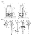
- FIG. 1 is a configuration diagram of a continuous casting machine to which the method of the present invention is applicable, wherein FIG. 1(a) is a front view thereof and FIG. 1(b) is a side view thereof.
- the continuous casting machine shown in FIG. 1 is of the vertical type and configured to cast a strand in a vertically downward direction.
- This continuous casting machine includes: a ladle 1 that contains molten steel; a mold 2 to which the molten steel is supplied from the ladle 1 via a submerged entry nozzle (not shown); and a movable reduction roll unit 4 that reduction-rolls a strand 3 that has been withdrawn downward from the mold 2.
- the mold 2 is composed of a set of half molds.
- the movable reduction roll unit 4 includes a pair of rolls 5 and a frame 6 that supports the rolls 5.
- the frame 6 is integral with the rolls 5 and vertically movable upward and downward along the strand 3 below the mold 2.
- FIG. 2 shows an embodiment in which the support region has a length about the same as that of the mold 2.
- the rolls 5 are configured to interchangeably function as pinch rolls that guide and support the strand 3 or as reduction rolls that reduction-roll the strand 3.
- the rolls 5 are hydraulically pressed from the back side toward the strand 3 to be brought into contact with the strand 3. Furthermore, the rolls 5 are connected to a large speed reducer 9 via a universal joint 8, and operate as drive rolls.
- the frame 6 is supported in a vertically movable manner by jack shafts 10 of vertically arranged four ball screw jacks, and is also given a driving force to be movable vertically upward and downward by the jack mechanism of the jack shafts 10.
- the rolls 5 are integral with the frame 6, they are vertically movable upward and downward along the strand 3, and therefore it is possible to change reduction rolling positions on the strand 3 and to move the rolls while they are performing reduction rolling.
- the move of the rolls 5 can be carried out by rotating the rolls 5 themselves in a state where they hold the strand 3 therebetween, and the direction of the move can be changed by changing the rotation direction of the rolls 5.
- the rolls 5 When the rolls 5 are not in contact with the strand 3, they can be moved by the jack mechanism of the jack shafts 10.
- FIG. 2 is a diagram illustrating a casting process in accordance with the continuous casting method of the present invention, wherein FIG. 2(a) shows a state at the start of casting; FIG. 2(b) shows a state during withdrawing of the strand; FIG. 2(c) shows a state in which the movable rolls have been moved to the lower end of the movable range after completion of the withdrawing; FIG. 2(d) shows a state in which the movable rolls are raised while they are reduction-rolling the strand; and FIG. 2(e) shows a state in which the reduction rolling has been completed.
- the continuous casting method of the present invention will be described. Firstly, casting of the strand 3 is started as shown in FIG. 2(a) , and the strand 3 is continuously withdrawn as shown in FIG. 2(b) . In this process, the rolls 5 are arranged immediately below the mold 2, or actually immediately below the support rolls 7, and are used as pinch rolls. After the strand 3 has been withdrawn up to the limitation of the continuous casting machine, the strand 3 is stopped to complete the withdrawing. Then, the rolls 5 are moved to the lowermost end of the movable range as shown in FIG. 2(c) . Thereafter, they are held waiting until the temperature of the central region of the strand 3 and the thickness of the solidified shell 3a reach optimal conditions for reduction rolling.
- the rolls 5 are pressed against the strand 3 to the extent that the amount of reduction of the strand 3 reaches a predetermined amount, and the rolls 5 are rotated in the direction opposite to the direction at the time of withdrawing, whereby the rolls 5 reduction-roll the strand 3 while being raised along the axis of the strand 3 as shown in FIG. 2(d) .
- the solidified shell 3a contains liquid steel 3b therewithin, the liquid steel 3b is ejected onto the meniscus in the upper portion as the rolls 5 are raised while reduction-rolling the strand 3 as shown in FIG. 2(e) .
- the amount of ejected molten steel is not so large in the case where the strand has a circular transverse cross section compared to a case where the cross section is of a different shape, although it depends on the size of the liquid core at the time of reduction-rolling of the strand. That is, the amount of ejected molten steel is approximately within the capacity of the mold 2.
- the rolls 5 while performing reduction rolling after the strand 3 has been completely solidified up to the core there is of course no ejection of liquid steel.
- the movable reduction roll unit 4 By using the movable reduction roll unit 4 to reduction-roll the strand 3 as described above, it is possible to efficiently reduction-roll the entire strand 3 and collapse centerline cavities and porosity regardless of the size of the cross section of the strand 3.
- the reduction rolling of the strand 3 may be performed continuously or intermittently only for portions that need reduction-rolling.
- the conditions for reduction rolling of the strand 3 can be varied by changing the speed at which the rolls 5 are raised. For example, by setting the speed for raising the rolls 5 to be the same as the speed for withdrawing the strand 3, it is possible to reduction-roll the entire strand 3 under the same conditions. The reason for this is as follows. Even after the reduction rolling by raising the rolls 5 is started, solidification of the liquid steel within the strand 3 proceeds with time to gradually diminish the liquid core. When the speed for raising the rolls 5 is set to be the same as the speed for withdrawing the strand 3, the length of time between the casting and the reduction rolling is constant at any reduction rolling position, and therefore the size of the liquid core is maintained substantially constant for all reduction rolling positions. It is to be noted that the speed for raising the rolls 5 may not necessarily be the same as the speed for withdrawing the strand 3.
- the rolls 5 may be raised to a predetermined position near the lower end of the mold 2 without reduction-rolling the strand 3, and then, from the position, the rolls 5 may perform reduction rolling on the strand 3 while being raised to an upper predetermined position. Conversely, the rolls 5 may be raised to the upper predetermined position above the predetermined position near the lower end of the mold 2 without reduction-rolling the strand 3, and then, from the position, the rolls 5 may perform reduction rolling on the strand 3 while being lowered to the predetermined position near the lower end of the mold 2.
- the use of movable rolls makes it possible to cast a strand having good internal quality, without replacing the continuous casting machine, regardless of the size of the strand cross section, at a low equipment cost and without causing deterioration of the surface quality. Furthermore, since the process is a continuous casting process, higher production yields than by ingot processes are achieved in casting strands.
- the type of continuous casting machines to which the present invention is applicable is not limited to the vertical type.
- the present invention may also be applicable to other forms of continuous casting machines such as those of the vertical bending type or the arcuate curved type as long as they have a section where casting can be performed in a vertically downward direction from immediately below the mold.
- the type of strand to which this casting is applied is preferably a strand having a circular transverse cross section.
- a strand having a circular transverse cross section is reduction-rolled by a pair of flat rolls, the solidified shell excluding portions that are in contact with the pair of rolls is not greatly deformed, and consequently deformation of only the portions that are in contact with the pair of rolls is sufficient to inhibit centerline cavities and porosity that are formed in a central region of the strand. Therefore, it is possible to efficiently collapse centerline cavities and porosity with a smaller reaction force of the reduction rolling.
- a movable reduction roll unit when included in a continuous casting machine, it is very difficult to install support rolls for a strand and roller aprons that hold the support rolls, which are installed in conventional continuous casting machines, because they geometrically interfere with the movable reduction roll unit. If support rolls are not installed, strand bulging may occur after static pressure of the liquid steel within the strand is applied to the solidified shell. However, when the transverse cross section of the strand is circular, the likelihood of the occurrence of bulging can be reduced even when the solidified shell is subjected to static pressure of the molten steel in the absence of support rolls to some extent.
- the reduction rolling of a strand may be carried out in a state where the liquid core remains within the strand, or in a state where the strand is completely solidified.
- internal cracking may occur in the strand when it is reduction-rolled with the liquid core remaining therein.
- reduction-rolling may be performed after the strand is completely solidified.
- centerline cavities and porosity that will occur are not relatively large, and therefore, in this case, collapsing of centerline cavities and porosity can be sufficiently achieved even with reduction rolling after the complete solidification.
- the strand to be cast was a small-size strand having a diameter of 300 mm and a length of 1800 mm, and the steel grade selected was a 13% Cr steel, which has a tendency to have increased centerline cavities and porosity.
- a continuous casting machine of the type shown in FIG. 1 was used. However, support rolls for supporting the solidified shell of the strand were not provided.
- the movable reduction roll unit included rolls having a diameter of 450 mm with a roll force of up to 100 t and a maximum roll torque of 50 t ⁇ m.
- the speed for raising the movable reduction roll unit for reduction rolling was set to 0.8 m/min and, after the casting of the strand over the entire length was completed, reduction rolling was performed on the strand over the entire length.
- the amount of reduction of the strand was 20 to 70 mm in terms of a reduction in the strand diameter in the rolling direction. It is to be noted that the cross section of the strand was flattened as a result of the reduction rolling.
- liquid core diameter The diameter of the liquid core (hereinafter referred to as "liquid core diameter") at the reduction rolling positions was 70 mm or 110 mm. These values were determined by defining the solid-liquid interface by an isotherm corresponding to a solid fraction of 0.8. The position of the interface where the solid fraction becomes 0.8 was determined by one-dimensional unsteady heat transfer and solidification analysis of the cylindrical cross section. The calculation results were compared against the results of measurement of the temperature of the strand surface, measurement of the temperature inside the strand by a thermocouple, and measurement of the liquid core diameter by addition of a tracer such as S, thereby confirming that the analysis is sufficiently accurate.
- a tracer such as S
- each strand was cut so that the longitudinal section passing through the center of the strand was exposed.
- the sectioned surface was ground and polished, and then investigation was made on the formation of centerline cavities, porosity, and shrinkage cavities. These defects appeared as voids in the section of the strand, and the extent of the defects was calculated as an area percentage of voids (fraction of voids) in the entire area of the cross section.
- the fraction of voids was divided by the fraction of voids of a strand which was cast separately from the reduction rolled strand without being subjected to reduction rolling by rolls (hereinafter referred to as "non-reduction-rolled strand"), and the result was defined as the area fraction of defects and was used as an index showing the extent of the formation of defects.
- the area of voids was measured using multipurpose image and photograph analysis software, but other methods may be used for the measurement.
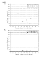
- FIG. 3 is a graph illustrating the relationship between the ratio of the reduction amount to the liquid core diameter of the strand (reduction amount/liquid core diameter) and the area fraction of defects, wherein FIG. 3(a) shows the results obtained in a constant region and FIG. 3(b) shows the results obtained in an upper portion of the strand.
- the upper portion of the strand refers to a region where centerline cavities and shrinkage cavities are formed in the case of a non-reduction-rolled strand, and in the case of a reduction-rolled strand, it refers to a region corresponding to the region in a non-reduction-rolled strand where centerline cavities and shrinkage cavities are formed.
- the constant region refers to a region other than the upper portion of the strand.
- the strand to be cast was a strand having a diameter of 800 mm and a length of 10 m, and the steel grade selected was a 13% Cr steel.
- the amount of molten steel used in the casting of this strand was about 40 t. This is equivalent to the amount for four ingots which are cast by a typical ingot process (the amount of molten steel: 10 t).
- feed from a feeder is used to prevent the formation of shrinkage cavities and centerline cavities in an upper portion of the ingot.
- molten steel in an amount of 10 % of the mass of the ingot is required per ingot, and therefore additional 4 t of molten steel will be required.
- the feed portion needs to be cut off, and therefore a loss is incurred accordingly, but no such loss is incurred in continuous casting processes.
- a continuous casting machine of the type shown in FIG. 1 was used.
- the mold used was a water-cooled mold made of copper having a diameter of 800 mm and a length of 800 mm.
- Immediately below the mold were provided support rolls with the length of the support region being 800 mm.
- the movable reduction roll unit included rolls having a diameter of 650 mm.
- Cooling of the strand was carried out by water spray cooling at a flow rate of 0.2 L/kg-steel. Withdrawing of the strand was carried out at a casting speed of 0.25 m/min, and the withdrawing was discontinued when the length of the strand became 10 m.
- the other test conditions than that were the same as those for the preliminary test as described above.
- the surface temperature of the strand when the withdrawing was discontinued was about 1220°C at a location 4 m in the casting direction from the meniscus in the mold and about 980°C at a location of 10 m.
- the liquid core diameter at this point of time was estimated to be about 620 mm at the location of 4 m from the meniscus and 500 mm at the location of 10 m with the solid fraction of 0.8 being used as a reference.
- the amount of reduction of the strand by the movable reduction roll unit was set to 225 mm, and the speed for raising the movable reduction roll unit was set to 0.25 m/min. This speed for raising the rolls is the same as the speed for withdrawing the strand, and therefore the conditions for reduction rolling (the liquid core diameter and the surface temperature of the strand at the location to be reduction-rolled) are uniform over the entire region of the strand.
- the liquid core diameter was about 500 mm and the surface temperature was 980°C at the location to be reduction-rolled at the start of reduction rolling.
- the reduction amount is 225 mm with respect to the liquid core diameter of 500 mm
- the value of the reduction amount/liquid core diameter is 0.45.
- the diameter of the rolls included in the movable reduction roll unit is 650 mm
- the deformation resistance of a 13% Cr steel, which is the steel to be cast is 6 kgf/mm 2 .
- the necessary roll force is 650 t.
- the strands that were cast under the above conditions had less centerline cavities, porosity, and shrinkage cavities than strands that were cast without the use of a movable reduction roll unit, and thus exhibited good internal quality and surface quality.
- higher production yields were obtained than in the casting of ingots of a comparable size by the ingot process.
Landscapes
- Engineering & Computer Science (AREA)
- Mechanical Engineering (AREA)
- Continuous Casting (AREA)
- Metal Rolling (AREA)
Abstract
Description
- The present invention relates to a method of continuously casting a strand designed to reduce the formation of centerline cavities, porosity, and shrinkage cavities, which are internal defects, by reduction-rolling the strand using a pair of rolls, and in particular, it relates to a continuous casting method using movable rolls.
- Currently, a typical process of manufacturing steel is carried out in such a manner that a strand is cast by a continuous casting process and the strand is subjected to processes such as slabbing, blooming, or billeting, and rolling to be formed into a final product. However, large size steel products having a large cross section such as steel products for a boiler tank and a large size die as a final product are manufactured in small lots, and they must be made from a cast steel having a large cross section. Therefore, at the present time, cast steels which are used for large size steel products are not produced by continuous casting, but are cast as a large size ingot by pouring molten steel into a mold and causing it to solidify therein. Hereinafter, this technique is referred to as "ingot process."
- Casting large size ingots by an ingot process is much less efficient than by a continuous casting process even though they are manufactured in small lots. Moreover, in view of the need for feed from a feeder in an upper portion of the ingot, retention of molten steel in a sprue and a stalk, or the like, the production yield is very low. The term "feed from a feeder" as used herein refers to feeding of molten steel by an amount corresponding to the solidification shrinkage in order to prevent the formation of shrinkage cavities and shrinkage cracks due to solidification shrinkage of molten steel in ingot casting.
- Furthermore, when a strand having a large cross section is cast by a continuous casting process, centerline cavities, porosity, which is a bubble defect, and segregation that occur in a central region of a strand tend to become larger. The term "centerline cavities" as used herein refers to cavity defects that occur in a central region of an alloy slab when the slab is cast. Moreover, when the casting comes to an end, after the supply of molten steel into the mold is discontinued, large shrinkage cavities such as those seen in a typical ingot process occur due to solidification shrinkage over an area from the meniscus (molten steel surface) of the strand toward the downstream side along the casting direction. These internal defects or the like not only decrease the production yield, but, in some cases, remain in the final product and can be a major cause of product defects.
- As a method of producing a strand having a large cross section with good internal quality,
Patent Literature 1 proposes using an inverted tapered mold in a semi-continuous casting process for producing large size ingots such as extra thick flat ingots that are difficult to cast in conventional continuous casting machines because of their thickness. In addition,Patent Literature 1 discloses that the ingot quality can further be enhanced by heating the meniscus in the top (upper portion) of the ingot by electrical means. -
Patent Literature 2 discloses that, in continuous casting of a strand, the formation of internal defects such as centerline cavities and porosity can be reduced by employing, for the strand shape, a tapered shape in which the distance between the side surfaces of the strand gradually increases toward an upper portion. - In the meantime, it is generally known that continuous casting of a strand may include a process of performing reduction rolling on the strand surface during the last stage of solidification for the purpose of reducing internal defects such as porosity and segregation. For example,
Patent Literature 3 discloses a method of reduction-rolling a strand having a liquid core. - Using a tapered mold or employing a tapered shape for the strand shape as in the techniques disclosed in
Patent Literatures - In contrast, the technique of squashing internal porosity during its formation stage by reduction-rolling the strand at its surface using rolls or the like (in-line reduction rolling technique), as practiced in continuous casting by a typical continuous casting machine, is a decisive and very effective technique. However, when the in-line reduction rolling technique is employed in continuous casting of a strand having a large cross section, there are two problems as follows.
- The first problem is that, in the in-line reduction rolling technique, the collapsing of the porosity formed in a strand should not be carried out at a randomly selected stage of casting, but must be carried out at an optimal time for reduction rolling. For example, when the reduction rolling of the strand is to be carried out during the formation stage of the porosity, the optimal time is considered to be the last stage of solidification between the time in which the solid fraction at the central region is about 0.5 and the time of complete solidification. When the reduction rolling is to be carried out after complete solidification, the optimal time is considered to be a time immediately after solidification at which the temperature of the central region of the strand is still sufficiently high. Therefore, in a typical continuous casting process, reduction rolling devices such as reduction rolls are usually disposed at a specified location such as in the vicinity of the exit of the continuous casting machine.
- However, when a strand having a large cross section is cast, in order to reduction-roll the strand under optimal conditions for collapsing centerline cavities and porosity by reduction rolling devices installed in the vicinity of the exit of the continuous casting machine, it is necessary to extend the length of the continuous casting machine to ensure time before the strand completely solidifies. It is to be noted that the length from the meniscus in the mold to the position of the crater end of the strand is considered to be proportional to the square of the thickness of the strand. Thus, when a case of casting a strand having a thickness of 300 mm is used as a reference, for example, casting of a strand having a thickness of 900 mm would require a continuous casting machine nine times longer, and therefore would result in requiring considerable cost for construction.
- On the other hand, if it is impossible to extend the length of the continuous casting machine, one approach that may be considered to ensure the time before the strand completely solidifies is to reduce the casting speed. In general, the casting speed (the speed of the strand) at the position of the crater end is considered to be inversely proportional to the square of the thickness of the strand. Thus, when a case of casting a strand having a thickness of 300 mm at a rate of 1 m/min is used as a reference, for example, casting of a strand having a thickness of 900 mm would need to be performed at a rate of 0.11 m/min, which is a very slow speed. Such very slow speed casting causes insufficient heating at the meniscus in the mold, and leads to skinning of the meniscus, formation of a rippled casting surface due to shrinkage of the solidified shell at the meniscus, and the like, and therefore results in significant deterioration of the surface quality of the strand. In order to prevent the deterioration of the surface quality, using both plasma heating and Joule heat for meniscus heating may be considered, but it results in a high equipment cost and is uneconomical in terms of energy as described above.
- The second problem is that, in the case of a strand having a large cross section, the reduction force does not sufficiently penetrate into the depth of the strand and thus it may not be possible to fully collapse centerline cavities and porosity.
-
- Patent Literature 1: Japanese Patent Application Publication No.
S62-161445 - Patent Literature 2: Japanese Patent Application Publication No.
2004-243352 - Patent Literature 3: Japanese Patent Application Publication No.
2000-288705 - As described above, there are problems with the techniques of conventional continuous casting methods for reducing centerline cavities and porosity in a central region of a strand having a large cross section and reducing shrinkage cavities and centerline cavities in an upper portion of the strand, in terms of equipment cost and energy and in terms of surface quality.
- The present invention has been made in view of such problems with conventional techniques. Accordingly, it is an object of the present invention to provide a method which, in continuous casting, reduces centerline cavities and porosity in a central region of a strand and shrinkage cavities and centerline cavities in an upper portion of the strand regardless of the size of its cross section at a low equipment cost and without causing deterioration of the surface quality.
- In order to solve the above problems, the present inventors studied methods of reduction-rolling a strand in continuous casting. Consequently, they have found that, by using movable rolls to reduction-roll a strand, it is possible to perform reduction rolling at an optimal location for collapsing centerline cavities, porosity, and shrinkage cavities regardless of the size of the strand cross section. In this case, there is no need for adjusting the length of a continuous casting machine or the casting speed, which would be required in the case of using rolls fixed at a specified location, and therefore the equipment cost is very low.
- The present invention has been achieved based on the above-mentioned findings, and the summaries thereof are set forth in the following (1) to (3) relating to methods of continuously casting a strand.
- (1) A method of continuously casting a strand, characterized in that the method comprises: using a pair of rolls configured to interchangeably perform guiding and supporting of a strand and reduction rolling of the strand, and to be movable in a vertical direction along the strand below a mold, wherein, while the strand is being withdrawn, the pair of rolls is held in a stopped condition and guides and supports the strand, and after the withdrawing of the strand is completed, the pair of rolls is moved in a vertical direction and accordingly reduction-rolls the stopped strand.
- (2) The method of continuously casting a strand according to the above (1), characterized in that the move of the rolls while reduction-rolling the strand is in a vertically upward direction.
- (3) The method of continuously casting a strand according to the above (1) or (2), characterized in that the strand has a circular transverse cross section.
- With the method of continuously casting a strand according to the present invention, it is possible to significantly reduce centerline cavities, porosity, and shrinkage cavities regardless of the size of the strand cross section as well as to cast a strand with high production yields, using a continuous casting machine for which the equipment cost is low, without causing deterioration of the surface quality.
-
- [
FIG. 1] FIG. 1 is a configuration diagram of a continuous casting machine to which the method of the present invention is applicable, whereinFIG. 1(a) is a front view thereof andFIG. 1(b) is a side view thereof. - [
FIG. 2] FIG. 2 is a diagram illustrating a casting process in accordance with the continuous casting method of the present invention, whereinFIG. 2(a) shows a state at the start of casting;FIG. 2(b) shows a state during withdrawing of the strand;FIG. 2(c) shows a state in which the movable rolls have been moved to the lower end of the movable range after completion of the withdrawing;FIG. 2(d) shows a state in which the movable rolls are raised while they are reduction-rolling the strand; andFIG. 2(e) shows a state in which the reduction rolling has been completed. - [
FIG. 3] FIG. 3 is a graph illustrating the relationship between the ratio of the reduction amount to the liquid core diameter of the strand (reduction amount/liquid core diameter) and the area fraction of defects, whereinFIG. 3(a) shows the results obtained in a constant region andFIG. 3(b) shows the results obtained in an upper portion of the strand. -
FIG. 1 is a configuration diagram of a continuous casting machine to which the method of the present invention is applicable, whereinFIG. 1(a) is a front view thereof andFIG. 1(b) is a side view thereof. The continuous casting machine shown inFIG. 1 is of the vertical type and configured to cast a strand in a vertically downward direction. This continuous casting machine includes: aladle 1 that contains molten steel; amold 2 to which the molten steel is supplied from theladle 1 via a submerged entry nozzle (not shown); and a movablereduction roll unit 4 that reduction-rolls astrand 3 that has been withdrawn downward from themold 2. Themold 2 is composed of a set of half molds. The movablereduction roll unit 4 includes a pair ofrolls 5 and aframe 6 that supports therolls 5. Theframe 6 is integral with therolls 5 and vertically movable upward and downward along thestrand 3 below themold 2. - Immediately below the
mold 2 are arranged support rolls 7 as shown in later-describedFIG. 2 (not shown inFIG. 1 ), which form a support region for a solidifiedshell 3a of thestrand 3. In the continuous casting machine, it is preferred that the solidifiedshell 3a be supported, at least immediately below themold 2, at a region extending a length about one fourth to about the same as that of themold 2.FIG. 2 , which will be later described, shows an embodiment in which the support region has a length about the same as that of themold 2. - The
rolls 5 are configured to interchangeably function as pinch rolls that guide and support thestrand 3 or as reduction rolls that reduction-roll thestrand 3. Therolls 5 are hydraulically pressed from the back side toward thestrand 3 to be brought into contact with thestrand 3. Furthermore, therolls 5 are connected to alarge speed reducer 9 via a universal joint 8, and operate as drive rolls. - The
frame 6 is supported in a vertically movable manner byjack shafts 10 of vertically arranged four ball screw jacks, and is also given a driving force to be movable vertically upward and downward by the jack mechanism of thejack shafts 10. - Since the
rolls 5 are integral with theframe 6, they are vertically movable upward and downward along thestrand 3, and therefore it is possible to change reduction rolling positions on thestrand 3 and to move the rolls while they are performing reduction rolling. The move of therolls 5 can be carried out by rotating therolls 5 themselves in a state where they hold thestrand 3 therebetween, and the direction of the move can be changed by changing the rotation direction of therolls 5. When therolls 5 are not in contact with thestrand 3, they can be moved by the jack mechanism of thejack shafts 10. -
FIG. 2 is a diagram illustrating a casting process in accordance with the continuous casting method of the present invention, whereinFIG. 2(a) shows a state at the start of casting;FIG. 2(b) shows a state during withdrawing of the strand;FIG. 2(c) shows a state in which the movable rolls have been moved to the lower end of the movable range after completion of the withdrawing;FIG. 2(d) shows a state in which the movable rolls are raised while they are reduction-rolling the strand; andFIG. 2(e) shows a state in which the reduction rolling has been completed. - With reference to
FIG. 2 , the continuous casting method of the present invention will be described. Firstly, casting of thestrand 3 is started as shown inFIG. 2(a) , and thestrand 3 is continuously withdrawn as shown inFIG. 2(b) . In this process, therolls 5 are arranged immediately below themold 2, or actually immediately below the support rolls 7, and are used as pinch rolls. After thestrand 3 has been withdrawn up to the limitation of the continuous casting machine, thestrand 3 is stopped to complete the withdrawing. Then, therolls 5 are moved to the lowermost end of the movable range as shown inFIG. 2(c) . Thereafter, they are held waiting until the temperature of the central region of thestrand 3 and the thickness of the solidifiedshell 3a reach optimal conditions for reduction rolling. - After the state of the
strand 3 has reached optimal conditions for reduction rolling, therolls 5 are pressed against thestrand 3 to the extent that the amount of reduction of thestrand 3 reaches a predetermined amount, and therolls 5 are rotated in the direction opposite to the direction at the time of withdrawing, whereby therolls 5 reduction-roll thestrand 3 while being raised along the axis of thestrand 3 as shown inFIG. 2(d) . When the solidifiedshell 3a containsliquid steel 3b therewithin, theliquid steel 3b is ejected onto the meniscus in the upper portion as therolls 5 are raised while reduction-rolling thestrand 3 as shown inFIG. 2(e) . The amount of ejected molten steel is not so large in the case where the strand has a circular transverse cross section compared to a case where the cross section is of a different shape, although it depends on the size of the liquid core at the time of reduction-rolling of the strand. That is, the amount of ejected molten steel is approximately within the capacity of themold 2. On the other hand, when raising therolls 5 while performing reduction rolling after thestrand 3 has been completely solidified up to the core, there is of course no ejection of liquid steel. - By using the movable
reduction roll unit 4 to reduction-roll thestrand 3 as described above, it is possible to efficiently reduction-roll theentire strand 3 and collapse centerline cavities and porosity regardless of the size of the cross section of thestrand 3. The reduction rolling of thestrand 3 may be performed continuously or intermittently only for portions that need reduction-rolling. - The conditions for reduction rolling of the
strand 3 can be varied by changing the speed at which therolls 5 are raised. For example, by setting the speed for raising therolls 5 to be the same as the speed for withdrawing thestrand 3, it is possible to reduction-roll theentire strand 3 under the same conditions. The reason for this is as follows. Even after the reduction rolling by raising therolls 5 is started, solidification of the liquid steel within thestrand 3 proceeds with time to gradually diminish the liquid core. When the speed for raising therolls 5 is set to be the same as the speed for withdrawing thestrand 3, the length of time between the casting and the reduction rolling is constant at any reduction rolling position, and therefore the size of the liquid core is maintained substantially constant for all reduction rolling positions. It is to be noted that the speed for raising therolls 5 may not necessarily be the same as the speed for withdrawing thestrand 3. - When the target for inhibition is only the formation of shrinkage cavities and centerline cavities below the meniscus, the
rolls 5 may be raised to a predetermined position near the lower end of themold 2 without reduction-rolling thestrand 3, and then, from the position, therolls 5 may perform reduction rolling on thestrand 3 while being raised to an upper predetermined position. Conversely, therolls 5 may be raised to the upper predetermined position above the predetermined position near the lower end of themold 2 without reduction-rolling thestrand 3, and then, from the position, therolls 5 may perform reduction rolling on thestrand 3 while being lowered to the predetermined position near the lower end of themold 2. - With the above steps, an entire process from withdrawing of the strand to reduction rolling by raising the rolls is completed. Thus, a subsequent casting may be carried out by repeating the process shown in
FIG. 2 again after the strand is taken out. - As described above, the use of movable rolls makes it possible to cast a strand having good internal quality, without replacing the continuous casting machine, regardless of the size of the strand cross section, at a low equipment cost and without causing deterioration of the surface quality. Furthermore, since the process is a continuous casting process, higher production yields than by ingot processes are achieved in casting strands.
- In the description above, a continuous casting process using a vertical type continuous casting machine has been described, but the type of continuous casting machines to which the present invention is applicable is not limited to the vertical type. The present invention may also be applicable to other forms of continuous casting machines such as those of the vertical bending type or the arcuate curved type as long as they have a section where casting can be performed in a vertically downward direction from immediately below the mold.
- The type of strand to which this casting is applied is preferably a strand having a circular transverse cross section. When a strand having a circular transverse cross section is reduction-rolled by a pair of flat rolls, the solidified shell excluding portions that are in contact with the pair of rolls is not greatly deformed, and consequently deformation of only the portions that are in contact with the pair of rolls is sufficient to inhibit centerline cavities and porosity that are formed in a central region of the strand. Therefore, it is possible to efficiently collapse centerline cavities and porosity with a smaller reaction force of the reduction rolling.
- Furthermore, when a movable reduction roll unit is included in a continuous casting machine, it is very difficult to install support rolls for a strand and roller aprons that hold the support rolls, which are installed in conventional continuous casting machines, because they geometrically interfere with the movable reduction roll unit. If support rolls are not installed, strand bulging may occur after static pressure of the liquid steel within the strand is applied to the solidified shell. However, when the transverse cross section of the strand is circular, the likelihood of the occurrence of bulging can be reduced even when the solidified shell is subjected to static pressure of the molten steel in the absence of support rolls to some extent.
- The reduction rolling of a strand may be carried out in a state where the liquid core remains within the strand, or in a state where the strand is completely solidified. Depending on the grade of the steel to which the casting is applied, internal cracking may occur in the strand when it is reduction-rolled with the liquid core remaining therein. Thus, in such a case, reduction-rolling may be performed after the strand is completely solidified. Also, in some grades of steel, centerline cavities and porosity that will occur are not relatively large, and therefore, in this case, collapsing of centerline cavities and porosity can be sufficiently achieved even with reduction rolling after the complete solidification.
- To verify the advantageous effects of the method of continuously casting a strand of the present invention, the following casting tests (a preliminary test and a final test) were conducted.
- The strand to be cast was a small-size strand having a diameter of 300 mm and a length of 1800 mm, and the steel grade selected was a 13% Cr steel, which has a tendency to have increased centerline cavities and porosity. A continuous casting machine of the type shown in
FIG. 1 was used. However, support rolls for supporting the solidified shell of the strand were not provided. The movable reduction roll unit included rolls having a diameter of 450 mm with a roll force of up to 100 t and a maximum roll torque of 50 t· m. The speed for raising the movable reduction roll unit for reduction rolling was set to 0.8 m/min and, after the casting of the strand over the entire length was completed, reduction rolling was performed on the strand over the entire length. The amount of reduction of the strand was 20 to 70 mm in terms of a reduction in the strand diameter in the rolling direction. It is to be noted that the cross section of the strand was flattened as a result of the reduction rolling. - The diameter of the liquid core (hereinafter referred to as "liquid core diameter") at the reduction rolling positions was 70 mm or 110 mm. These values were determined by defining the solid-liquid interface by an isotherm corresponding to a solid fraction of 0.8. The position of the interface where the solid fraction becomes 0.8 was determined by one-dimensional unsteady heat transfer and solidification analysis of the cylindrical cross section. The calculation results were compared against the results of measurement of the temperature of the strand surface, measurement of the temperature inside the strand by a thermocouple, and measurement of the liquid core diameter by addition of a tracer such as S, thereby confirming that the analysis is sufficiently accurate.
- After completion of the test, each strand was cut so that the longitudinal section passing through the center of the strand was exposed. The sectioned surface was ground and polished, and then investigation was made on the formation of centerline cavities, porosity, and shrinkage cavities. These defects appeared as voids in the section of the strand, and the extent of the defects was calculated as an area percentage of voids (fraction of voids) in the entire area of the cross section. The fraction of voids was divided by the fraction of voids of a strand which was cast separately from the reduction rolled strand without being subjected to reduction rolling by rolls (hereinafter referred to as "non-reduction-rolled strand"), and the result was defined as the area fraction of defects and was used as an index showing the extent of the formation of defects. The area of voids was measured using multipurpose image and photograph analysis software, but other methods may be used for the measurement.
-
FIG. 3 is a graph illustrating the relationship between the ratio of the reduction amount to the liquid core diameter of the strand (reduction amount/liquid core diameter) and the area fraction of defects, whereinFIG. 3(a) shows the results obtained in a constant region andFIG. 3(b) shows the results obtained in an upper portion of the strand. The upper portion of the strand refers to a region where centerline cavities and shrinkage cavities are formed in the case of a non-reduction-rolled strand, and in the case of a reduction-rolled strand, it refers to a region corresponding to the region in a non-reduction-rolled strand where centerline cavities and shrinkage cavities are formed. The constant region refers to a region other than the upper portion of the strand. - As shown in
FIG. 3(a) , it has been found that, when the value of the reduction amount/liquid core diameter is increased, a significant reduction of centerline cavities and porosity can be achieved. In addition, fromFIG. 3(b) , it has been observed that an even greater effect of reducing defects is produced in an upper portion of a strand than in a constant region. - Based on the results of the preliminary test, casting conditions were studied for a case where the quantity of molten steel is increased as the final test. The strand to be cast was a strand having a diameter of 800 mm and a length of 10 m, and the steel grade selected was a 13% Cr steel. The amount of molten steel used in the casting of this strand was about 40 t. This is equivalent to the amount for four ingots which are cast by a typical ingot process (the amount of molten steel: 10 t). In typical ingot casting, feed from a feeder is used to prevent the formation of shrinkage cavities and centerline cavities in an upper portion of the ingot. For the feed, molten steel in an amount of 10 % of the mass of the ingot is required per ingot, and therefore additional 4 t of molten steel will be required. After the ingot is cast, the feed portion needs to be cut off, and therefore a loss is incurred accordingly, but no such loss is incurred in continuous casting processes.
- A continuous casting machine of the type shown in
FIG. 1 was used. The mold used was a water-cooled mold made of copper having a diameter of 800 mm and a length of 800 mm. Immediately below the mold were provided support rolls with the length of the support region being 800 mm. The movable reduction roll unit included rolls having a diameter of 650 mm. Cooling of the strand was carried out by water spray cooling at a flow rate of 0.2 L/kg-steel. Withdrawing of the strand was carried out at a casting speed of 0.25 m/min, and the withdrawing was discontinued when the length of the strand became 10 m. The other test conditions than that were the same as those for the preliminary test as described above. - According to heat transfer and solidification analysis that was performed on continuous casting under the above conditions, it was estimated that the surface temperature of the strand when the withdrawing was discontinued was about 1220°C at a location 4 m in the casting direction from the meniscus in the mold and about 980°C at a location of 10 m. The liquid core diameter at this point of time was estimated to be about 620 mm at the location of 4 m from the meniscus and 500 mm at the location of 10 m with the solid fraction of 0.8 being used as a reference. Based on the analysis results, the amount of reduction of the strand by the movable reduction roll unit was set to 225 mm, and the speed for raising the movable reduction roll unit was set to 0.25 m/min. This speed for raising the rolls is the same as the speed for withdrawing the strand, and therefore the conditions for reduction rolling (the liquid core diameter and the surface temperature of the strand at the location to be reduction-rolled) are uniform over the entire region of the strand.
- In this case, the liquid core diameter was about 500 mm and the surface temperature was 980°C at the location to be reduction-rolled at the start of reduction rolling. When the reduction amount is 225 mm with respect to the liquid core diameter of 500 mm, the value of the reduction amount/liquid core diameter is 0.45. Thus, it is estimated from
FIG. 3 , which shows the results of the preliminary test, that the area fraction of defects will be significantly reduced both for the constant region and for the upper portion of the strand, at 20% and 4.8%, respectively. The diameter of the rolls included in the movable reduction roll unit is 650 mm, and the deformation resistance of a 13% Cr steel, which is the steel to be cast, is 6 kgf/mm2. Thus, assuming that the contact angle between the roll and the strand is 32°, the necessary roll force is 650 t. - The strands that were cast under the above conditions had less centerline cavities, porosity, and shrinkage cavities than strands that were cast without the use of a movable reduction roll unit, and thus exhibited good internal quality and surface quality. In addition, higher production yields were obtained than in the casting of ingots of a comparable size by the ingot process.
- With the method of continuously casting a strand according to the present invention, it is possible to significantly reduce centerline cavities, porosity, and shrinkage cavities regardless of the size of the strand cross section as well as to cast a strand with high production yields, using a continuous casting machine for which the equipment cost is low, without causing deterioration of the surface quality.
- 1: ladle, 2: mold, 3: strand, 3a: solidified shell, 3b: liquid steel, 4: movable reduction roll unit, 5: roll pair, 6: frame, 7: support rolls, 8: universal joint, 9: large speed reducer, 10: jack shaft
Claims (3)
- A method of continuously casting a strand, characterized in that the method comprises:using a pair of rolls configured to interchangeably perform guiding and supporting of a strand and reduction rolling of the strand, and to be movable in a vertical direction along the strand below a mold,wherein, while the strand is being withdrawn, the pair of rolls is held in a stopped condition and guides and supports the strand, and after the withdrawing of the strand is completed, the pair of rolls is moved in a vertical direction and accordingly reduction-rolls the stopped strand.
- The method of continuously casting a strand according to claim 1, characterized in that the move of the rolls while reduction-rolling the strand is in a vertically upward direction.
- The method of continuously casting a strand according to claim 1 or 2, characterized in that the strand has a circular transverse cross section.
Priority Applications (1)
| Application Number | Priority Date | Filing Date | Title |
|---|---|---|---|
| PL12877100T PL2857122T3 (en) | 2012-05-24 | 2012-05-24 | Continuous casting method for slab |
Applications Claiming Priority (1)
| Application Number | Priority Date | Filing Date | Title |
|---|---|---|---|
| PCT/JP2012/003388 WO2013175536A1 (en) | 2012-05-24 | 2012-05-24 | Continuous casting method for slab |
Publications (3)
| Publication Number | Publication Date |
|---|---|
| EP2857122A1 true EP2857122A1 (en) | 2015-04-08 |
| EP2857122A4 EP2857122A4 (en) | 2016-01-20 |
| EP2857122B1 EP2857122B1 (en) | 2017-09-20 |
Family
ID=49623271
Family Applications (1)
| Application Number | Title | Priority Date | Filing Date |
|---|---|---|---|
| EP12877100.3A Not-in-force EP2857122B1 (en) | 2012-05-24 | 2012-05-24 | Continuous casting method for slab |
Country Status (8)
| Country | Link |
|---|---|
| EP (1) | EP2857122B1 (en) |
| JP (1) | JPWO2013175536A1 (en) |
| KR (1) | KR20140147883A (en) |
| CN (1) | CN104334297A (en) |
| ES (1) | ES2651136T3 (en) |
| IN (1) | IN2014DN08553A (en) |
| PL (1) | PL2857122T3 (en) |
| WO (1) | WO2013175536A1 (en) |
Families Citing this family (1)
| Publication number | Priority date | Publication date | Assignee | Title |
|---|---|---|---|---|
| CN107116192A (en) * | 2017-06-27 | 2017-09-01 | 中冶京诚工程技术有限公司 | Continuous casting billet pressing equipment |
Family Cites Families (12)
| Publication number | Priority date | Publication date | Assignee | Title |
|---|---|---|---|---|
| JPS62161445A (en) | 1986-01-10 | 1987-07-17 | Kawasaki Steel Corp | Steel ingot making method |
| JPS6333163A (en) * | 1986-07-26 | 1988-02-12 | Kawasaki Steel Corp | Production for large size ingot |
| JP2964560B2 (en) * | 1989-08-16 | 1999-10-18 | 大同特殊鋼株式会社 | Vertical continuous casting equipment |
| JP2894131B2 (en) * | 1992-12-26 | 1999-05-24 | 住友金属工業株式会社 | Large slab production method |
| JP3427546B2 (en) * | 1995-01-30 | 2003-07-22 | 大同特殊鋼株式会社 | Dissimilar steel continuous casting method |
| JP3402251B2 (en) | 1999-04-06 | 2003-05-06 | 住友金属工業株式会社 | Continuous casting method |
| DE19921296A1 (en) * | 1999-05-07 | 2000-11-09 | Sms Demag Ag | Method and device for the production of continuously cast steel products |
| CN2579561Y (en) * | 2002-11-27 | 2003-10-15 | 钢铁研究总院 | Continuous blank withdrawal straightening device with light pressing function |
| JP2004243352A (en) | 2003-02-12 | 2004-09-02 | Daido Steel Co Ltd | Continuous casting method |
| JP5359892B2 (en) * | 2010-01-08 | 2013-12-04 | 新日鐵住金株式会社 | Steel continuous casting method |
| JP5477269B2 (en) * | 2010-12-03 | 2014-04-23 | 新日鐵住金株式会社 | Continuous casting method for slabs |
| JP5741402B2 (en) * | 2011-11-25 | 2015-07-01 | 新日鐵住金株式会社 | Continuous casting method for circular section slabs |
-
2012
- 2012-05-24 ES ES12877100.3T patent/ES2651136T3/en active Active
- 2012-05-24 JP JP2014516513A patent/JPWO2013175536A1/en active Pending
- 2012-05-24 PL PL12877100T patent/PL2857122T3/en unknown
- 2012-05-24 WO PCT/JP2012/003388 patent/WO2013175536A1/en not_active Ceased
- 2012-05-24 KR KR1020147031133A patent/KR20140147883A/en not_active Ceased
- 2012-05-24 IN IN8553DEN2014 patent/IN2014DN08553A/en unknown
- 2012-05-24 EP EP12877100.3A patent/EP2857122B1/en not_active Not-in-force
- 2012-05-24 CN CN201280073444.7A patent/CN104334297A/en active Pending
Also Published As
| Publication number | Publication date |
|---|---|
| JPWO2013175536A1 (en) | 2016-01-12 |
| CN104334297A (en) | 2015-02-04 |
| EP2857122A4 (en) | 2016-01-20 |
| EP2857122B1 (en) | 2017-09-20 |
| IN2014DN08553A (en) | 2015-05-15 |
| ES2651136T3 (en) | 2018-01-24 |
| PL2857122T3 (en) | 2018-02-28 |
| WO2013175536A1 (en) | 2013-11-28 |
| KR20140147883A (en) | 2014-12-30 |
Similar Documents
| Publication | Publication Date | Title |
|---|---|---|
| TWI655979B (en) | Steel continuous casting method | |
| JP5835531B2 (en) | Continuous casting method for slabs for extra heavy steel plates | |
| KR101984634B1 (en) | Process engineering measures in a strand casting machine at the beginning of casting, at the end of casting, and during the manufacturing of a transition piece | |
| JP4055689B2 (en) | Continuous casting method | |
| JP6390718B2 (en) | Continuously cast slab, manufacturing method and manufacturing apparatus thereof, manufacturing method and manufacturing apparatus of thick steel plate | |
| JP5477269B2 (en) | Continuous casting method for slabs | |
| EP2857122B1 (en) | Continuous casting method for slab | |
| JP5741402B2 (en) | Continuous casting method for circular section slabs | |
| CN111659863B (en) | Retrofitting of continuous casting installations for billets or blooms | |
| JP5157664B2 (en) | Continuous casting method of round slabs for seamless steel pipes | |
| JP5343746B2 (en) | Continuous casting method of round slabs for seamless steel pipes | |
| JP6784222B2 (en) | Manufacturing method of thin-walled slabs | |
| JP3374761B2 (en) | Continuous cast slab, continuous casting method thereof, and method of manufacturing thick steel plate | |
| JP5790385B2 (en) | Continuous casting method of round slab for 13Cr seamless steel pipe | |
| JP4285288B2 (en) | Steel continuous casting method | |
| JP5195636B2 (en) | Manufacturing method of continuous cast slab | |
| JP5973703B2 (en) | Seamless pipe manufacturing method | |
| JP5387205B2 (en) | Continuous casting method and continuous casting equipment for round slab | |
| JP7364887B2 (en) | Method for producing thin slabs | |
| JP2011121073A (en) | Method of manufacturing large section steel | |
| RU2198064C2 (en) | Method for making rectangular billet and apparatus for performing the same | |
| JPH0999349A (en) | Continuous casting method for round slabs for steel bars | |
| JP4934438B2 (en) | Method and apparatus for producing oxygen-free copper wire or copper alloy wire | |
| RU2496603C1 (en) | Method for obtaining rectangular workpiece, and device for its implementation | |
| KR100540922B1 (en) | Method and Apparatus for Producing Thin Slabs in a Continuous Casting Plant |
Legal Events
| Date | Code | Title | Description |
|---|---|---|---|
| PUAI | Public reference made under article 153(3) epc to a published international application that has entered the european phase |
Free format text: ORIGINAL CODE: 0009012 |
|
| 17P | Request for examination filed |
Effective date: 20141219 |
|
| AK | Designated contracting states |
Kind code of ref document: A1 Designated state(s): AL AT BE BG CH CY CZ DE DK EE ES FI FR GB GR HR HU IE IS IT LI LT LU LV MC MK MT NL NO PL PT RO RS SE SI SK SM TR |
|
| AX | Request for extension of the european patent |
Extension state: BA ME |
|
| DAX | Request for extension of the european patent (deleted) | ||
| REG | Reference to a national code |
Ref country code: DE Ref legal event code: R079 Ref document number: 602012037681 Country of ref document: DE Free format text: PREVIOUS MAIN CLASS: B22D0011128000 Ipc: B22D0011120000 |
|
| RA4 | Supplementary search report drawn up and despatched (corrected) |
Effective date: 20151223 |
|
| RIC1 | Information provided on ipc code assigned before grant |
Ipc: B21B 1/46 20060101ALI20151217BHEP Ipc: B22D 11/20 20060101ALI20151217BHEP Ipc: B22D 11/14 20060101ALI20151217BHEP Ipc: B22D 11/128 20060101ALI20151217BHEP Ipc: B22D 11/00 20060101ALI20151217BHEP Ipc: B22D 11/12 20060101AFI20151217BHEP |
|
| GRAP | Despatch of communication of intention to grant a patent |
Free format text: ORIGINAL CODE: EPIDOSNIGR1 |
|
| INTG | Intention to grant announced |
Effective date: 20170608 |
|
| GRAS | Grant fee paid |
Free format text: ORIGINAL CODE: EPIDOSNIGR3 |
|
| GRAA | (expected) grant |
Free format text: ORIGINAL CODE: 0009210 |
|
| AK | Designated contracting states |
Kind code of ref document: B1 Designated state(s): AL AT BE BG CH CY CZ DE DK EE ES FI FR GB GR HR HU IE IS IT LI LT LU LV MC MK MT NL NO PL PT RO RS SE SI SK SM TR |
|
| REG | Reference to a national code |
Ref country code: GB Ref legal event code: FG4D |
|
| REG | Reference to a national code |
Ref country code: CH Ref legal event code: EP |
|
| REG | Reference to a national code |
Ref country code: NL Ref legal event code: FP |
|
| REG | Reference to a national code |
Ref country code: AT Ref legal event code: REF Ref document number: 929751 Country of ref document: AT Kind code of ref document: T Effective date: 20171015 |
|
| REG | Reference to a national code |
Ref country code: IE Ref legal event code: FG4D |
|
| REG | Reference to a national code |
Ref country code: DE Ref legal event code: R096 Ref document number: 602012037681 Country of ref document: DE |
|
| REG | Reference to a national code |
Ref country code: SE Ref legal event code: TRGR |
|
| REG | Reference to a national code |
Ref country code: ES Ref legal event code: FG2A Ref document number: 2651136 Country of ref document: ES Kind code of ref document: T3 Effective date: 20180124 |
|
| PG25 | Lapsed in a contracting state [announced via postgrant information from national office to epo] |
Ref country code: FI Free format text: LAPSE BECAUSE OF FAILURE TO SUBMIT A TRANSLATION OF THE DESCRIPTION OR TO PAY THE FEE WITHIN THE PRESCRIBED TIME-LIMIT Effective date: 20170920 Ref country code: LT Free format text: LAPSE BECAUSE OF FAILURE TO SUBMIT A TRANSLATION OF THE DESCRIPTION OR TO PAY THE FEE WITHIN THE PRESCRIBED TIME-LIMIT Effective date: 20170920 Ref country code: HR Free format text: LAPSE BECAUSE OF FAILURE TO SUBMIT A TRANSLATION OF THE DESCRIPTION OR TO PAY THE FEE WITHIN THE PRESCRIBED TIME-LIMIT Effective date: 20170920 Ref country code: NO Free format text: LAPSE BECAUSE OF FAILURE TO SUBMIT A TRANSLATION OF THE DESCRIPTION OR TO PAY THE FEE WITHIN THE PRESCRIBED TIME-LIMIT Effective date: 20171220 |
|
| REG | Reference to a national code |
Ref country code: LT Ref legal event code: MG4D |
|
| PG25 | Lapsed in a contracting state [announced via postgrant information from national office to epo] |
Ref country code: GR Free format text: LAPSE BECAUSE OF FAILURE TO SUBMIT A TRANSLATION OF THE DESCRIPTION OR TO PAY THE FEE WITHIN THE PRESCRIBED TIME-LIMIT Effective date: 20171221 Ref country code: BG Free format text: LAPSE BECAUSE OF FAILURE TO SUBMIT A TRANSLATION OF THE DESCRIPTION OR TO PAY THE FEE WITHIN THE PRESCRIBED TIME-LIMIT Effective date: 20171220 Ref country code: RS Free format text: LAPSE BECAUSE OF FAILURE TO SUBMIT A TRANSLATION OF THE DESCRIPTION OR TO PAY THE FEE WITHIN THE PRESCRIBED TIME-LIMIT Effective date: 20170920 Ref country code: LV Free format text: LAPSE BECAUSE OF FAILURE TO SUBMIT A TRANSLATION OF THE DESCRIPTION OR TO PAY THE FEE WITHIN THE PRESCRIBED TIME-LIMIT Effective date: 20170920 |
|
| PG25 | Lapsed in a contracting state [announced via postgrant information from national office to epo] |
Ref country code: RO Free format text: LAPSE BECAUSE OF FAILURE TO SUBMIT A TRANSLATION OF THE DESCRIPTION OR TO PAY THE FEE WITHIN THE PRESCRIBED TIME-LIMIT Effective date: 20170920 Ref country code: CZ Free format text: LAPSE BECAUSE OF FAILURE TO SUBMIT A TRANSLATION OF THE DESCRIPTION OR TO PAY THE FEE WITHIN THE PRESCRIBED TIME-LIMIT Effective date: 20170920 |
|
| REG | Reference to a national code |
Ref country code: FR Ref legal event code: PLFP Year of fee payment: 7 |
|
| PG25 | Lapsed in a contracting state [announced via postgrant information from national office to epo] |
Ref country code: SM Free format text: LAPSE BECAUSE OF FAILURE TO SUBMIT A TRANSLATION OF THE DESCRIPTION OR TO PAY THE FEE WITHIN THE PRESCRIBED TIME-LIMIT Effective date: 20170920 Ref country code: SK Free format text: LAPSE BECAUSE OF FAILURE TO SUBMIT A TRANSLATION OF THE DESCRIPTION OR TO PAY THE FEE WITHIN THE PRESCRIBED TIME-LIMIT Effective date: 20170920 Ref country code: EE Free format text: LAPSE BECAUSE OF FAILURE TO SUBMIT A TRANSLATION OF THE DESCRIPTION OR TO PAY THE FEE WITHIN THE PRESCRIBED TIME-LIMIT Effective date: 20170920 Ref country code: IS Free format text: LAPSE BECAUSE OF FAILURE TO SUBMIT A TRANSLATION OF THE DESCRIPTION OR TO PAY THE FEE WITHIN THE PRESCRIBED TIME-LIMIT Effective date: 20180120 |
|
| REG | Reference to a national code |
Ref country code: DE Ref legal event code: R097 Ref document number: 602012037681 Country of ref document: DE |
|
| PLBE | No opposition filed within time limit |
Free format text: ORIGINAL CODE: 0009261 |
|
| STAA | Information on the status of an ep patent application or granted ep patent |
Free format text: STATUS: NO OPPOSITION FILED WITHIN TIME LIMIT |
|
| PG25 | Lapsed in a contracting state [announced via postgrant information from national office to epo] |
Ref country code: DK Free format text: LAPSE BECAUSE OF FAILURE TO SUBMIT A TRANSLATION OF THE DESCRIPTION OR TO PAY THE FEE WITHIN THE PRESCRIBED TIME-LIMIT Effective date: 20170920 |
|
| 26N | No opposition filed |
Effective date: 20180621 |
|
| PG25 | Lapsed in a contracting state [announced via postgrant information from national office to epo] |
Ref country code: SI Free format text: LAPSE BECAUSE OF FAILURE TO SUBMIT A TRANSLATION OF THE DESCRIPTION OR TO PAY THE FEE WITHIN THE PRESCRIBED TIME-LIMIT Effective date: 20170920 |
|
| REG | Reference to a national code |
Ref country code: CH Ref legal event code: PL |
|
| PG25 | Lapsed in a contracting state [announced via postgrant information from national office to epo] |
Ref country code: MC Free format text: LAPSE BECAUSE OF FAILURE TO SUBMIT A TRANSLATION OF THE DESCRIPTION OR TO PAY THE FEE WITHIN THE PRESCRIBED TIME-LIMIT Effective date: 20170920 |
|
| REG | Reference to a national code |
Ref country code: IE Ref legal event code: MM4A |
|
| PG25 | Lapsed in a contracting state [announced via postgrant information from national office to epo] |
Ref country code: CH Free format text: LAPSE BECAUSE OF NON-PAYMENT OF DUE FEES Effective date: 20180531 Ref country code: LI Free format text: LAPSE BECAUSE OF NON-PAYMENT OF DUE FEES Effective date: 20180531 |
|
| PG25 | Lapsed in a contracting state [announced via postgrant information from national office to epo] |
Ref country code: LU Free format text: LAPSE BECAUSE OF NON-PAYMENT OF DUE FEES Effective date: 20180524 |
|
| REG | Reference to a national code |
Ref country code: AT Ref legal event code: UEP Ref document number: 929751 Country of ref document: AT Kind code of ref document: T Effective date: 20170920 |
|
| PG25 | Lapsed in a contracting state [announced via postgrant information from national office to epo] |
Ref country code: IE Free format text: LAPSE BECAUSE OF NON-PAYMENT OF DUE FEES Effective date: 20180524 |
|
| REG | Reference to a national code |
Ref country code: DE Ref legal event code: R082 Ref document number: 602012037681 Country of ref document: DE Representative=s name: ZIMMERMANN & PARTNER PATENTANWAELTE MBB, DE Ref country code: DE Ref legal event code: R081 Ref document number: 602012037681 Country of ref document: DE Owner name: NIPPON STEEL CORPORATION, JP Free format text: FORMER OWNER: NIPPON STEEL & SUMITOMO METAL CORPORATION, TOKYO, JP |
|
| PG25 | Lapsed in a contracting state [announced via postgrant information from national office to epo] |
Ref country code: MT Free format text: LAPSE BECAUSE OF NON-PAYMENT OF DUE FEES Effective date: 20180524 |
|
| PG25 | Lapsed in a contracting state [announced via postgrant information from national office to epo] |
Ref country code: TR Free format text: LAPSE BECAUSE OF FAILURE TO SUBMIT A TRANSLATION OF THE DESCRIPTION OR TO PAY THE FEE WITHIN THE PRESCRIBED TIME-LIMIT Effective date: 20170920 |
|
| PG25 | Lapsed in a contracting state [announced via postgrant information from national office to epo] |
Ref country code: PT Free format text: LAPSE BECAUSE OF FAILURE TO SUBMIT A TRANSLATION OF THE DESCRIPTION OR TO PAY THE FEE WITHIN THE PRESCRIBED TIME-LIMIT Effective date: 20170920 |
|
| PG25 | Lapsed in a contracting state [announced via postgrant information from national office to epo] |
Ref country code: HU Free format text: LAPSE BECAUSE OF FAILURE TO SUBMIT A TRANSLATION OF THE DESCRIPTION OR TO PAY THE FEE WITHIN THE PRESCRIBED TIME-LIMIT; INVALID AB INITIO Effective date: 20120524 Ref country code: MK Free format text: LAPSE BECAUSE OF NON-PAYMENT OF DUE FEES Effective date: 20170920 Ref country code: CY Free format text: LAPSE BECAUSE OF FAILURE TO SUBMIT A TRANSLATION OF THE DESCRIPTION OR TO PAY THE FEE WITHIN THE PRESCRIBED TIME-LIMIT Effective date: 20170920 |
|
| PG25 | Lapsed in a contracting state [announced via postgrant information from national office to epo] |
Ref country code: AL Free format text: LAPSE BECAUSE OF FAILURE TO SUBMIT A TRANSLATION OF THE DESCRIPTION OR TO PAY THE FEE WITHIN THE PRESCRIBED TIME-LIMIT Effective date: 20170920 |
|
| PGFP | Annual fee paid to national office [announced via postgrant information from national office to epo] |
Ref country code: ES Payment date: 20200601 Year of fee payment: 9 Ref country code: FR Payment date: 20200414 Year of fee payment: 9 Ref country code: DE Payment date: 20200512 Year of fee payment: 9 Ref country code: NL Payment date: 20200417 Year of fee payment: 9 |
|
| PGFP | Annual fee paid to national office [announced via postgrant information from national office to epo] |
Ref country code: GB Payment date: 20200513 Year of fee payment: 9 Ref country code: SE Payment date: 20200512 Year of fee payment: 9 Ref country code: IT Payment date: 20200414 Year of fee payment: 9 Ref country code: PL Payment date: 20200415 Year of fee payment: 9 Ref country code: BE Payment date: 20200416 Year of fee payment: 9 |
|
| PGFP | Annual fee paid to national office [announced via postgrant information from national office to epo] |
Ref country code: AT Payment date: 20200428 Year of fee payment: 9 |
|
| REG | Reference to a national code |
Ref country code: DE Ref legal event code: R119 Ref document number: 602012037681 Country of ref document: DE |
|
| REG | Reference to a national code |
Ref country code: SE Ref legal event code: EUG |
|
| REG | Reference to a national code |
Ref country code: NL Ref legal event code: MM Effective date: 20210601 |
|
| REG | Reference to a national code |
Ref country code: AT Ref legal event code: MM01 Ref document number: 929751 Country of ref document: AT Kind code of ref document: T Effective date: 20210524 |
|
| GBPC | Gb: european patent ceased through non-payment of renewal fee |
Effective date: 20210524 |
|
| PG25 | Lapsed in a contracting state [announced via postgrant information from national office to epo] |
Ref country code: AT Free format text: LAPSE BECAUSE OF NON-PAYMENT OF DUE FEES Effective date: 20210524 Ref country code: SE Free format text: LAPSE BECAUSE OF NON-PAYMENT OF DUE FEES Effective date: 20210525 |
|
| REG | Reference to a national code |
Ref country code: BE Ref legal event code: MM Effective date: 20210531 |
|
| PG25 | Lapsed in a contracting state [announced via postgrant information from national office to epo] |
Ref country code: GB Free format text: LAPSE BECAUSE OF NON-PAYMENT OF DUE FEES Effective date: 20210524 Ref country code: DE Free format text: LAPSE BECAUSE OF NON-PAYMENT OF DUE FEES Effective date: 20211201 |
|
| PG25 | Lapsed in a contracting state [announced via postgrant information from national office to epo] |
Ref country code: NL Free format text: LAPSE BECAUSE OF NON-PAYMENT OF DUE FEES Effective date: 20210601 Ref country code: FR Free format text: LAPSE BECAUSE OF NON-PAYMENT OF DUE FEES Effective date: 20210531 |
|
| PG25 | Lapsed in a contracting state [announced via postgrant information from national office to epo] |
Ref country code: BE Free format text: LAPSE BECAUSE OF NON-PAYMENT OF DUE FEES Effective date: 20210531 |
|
| REG | Reference to a national code |
Ref country code: ES Ref legal event code: FD2A Effective date: 20220804 |
|
| PG25 | Lapsed in a contracting state [announced via postgrant information from national office to epo] |
Ref country code: ES Free format text: LAPSE BECAUSE OF NON-PAYMENT OF DUE FEES Effective date: 20210525 |
|
| PG25 | Lapsed in a contracting state [announced via postgrant information from national office to epo] |
Ref country code: PL Free format text: LAPSE BECAUSE OF NON-PAYMENT OF DUE FEES Effective date: 20210524 |
|
| PG25 | Lapsed in a contracting state [announced via postgrant information from national office to epo] |
Ref country code: IT Free format text: LAPSE BECAUSE OF NON-PAYMENT OF DUE FEES Effective date: 20200524 |
|
| PG25 | Lapsed in a contracting state [announced via postgrant information from national office to epo] |
Ref country code: IT Free format text: LAPSE BECAUSE OF NON-PAYMENT OF DUE FEES Effective date: 20210524 |