EP2856061B1 - Heat exchanger with adapter module - Google Patents
Heat exchanger with adapter module Download PDFInfo
- Publication number
- EP2856061B1 EP2856061B1 EP13782050.2A EP13782050A EP2856061B1 EP 2856061 B1 EP2856061 B1 EP 2856061B1 EP 13782050 A EP13782050 A EP 13782050A EP 2856061 B1 EP2856061 B1 EP 2856061B1
- Authority
- EP
- European Patent Office
- Prior art keywords
- heat exchanger
- fluid
- adapter
- module
- plate
- Prior art date
- Legal status (The legal status is an assumption and is not a legal conclusion. Google has not performed a legal analysis and makes no representation as to the accuracy of the status listed.)
- Active
Links
- 239000012530 fluid Substances 0.000 claims description 223
- 238000004891 communication Methods 0.000 claims description 30
- 238000005219 brazing Methods 0.000 claims description 5
- 239000003921 oil Substances 0.000 description 39
- 230000005540 biological transmission Effects 0.000 description 26
- 239000002826 coolant Substances 0.000 description 20
- 239000010705 motor oil Substances 0.000 description 16
- 238000007789 sealing Methods 0.000 description 7
- XAGFODPZIPBFFR-UHFFFAOYSA-N aluminium Chemical compound [Al] XAGFODPZIPBFFR-UHFFFAOYSA-N 0.000 description 6
- 229910052782 aluminium Inorganic materials 0.000 description 6
- 238000004519 manufacturing process Methods 0.000 description 6
- 230000008901 benefit Effects 0.000 description 2
- 238000005266 casting Methods 0.000 description 2
- 238000001816 cooling Methods 0.000 description 2
- 125000004122 cyclic group Chemical group 0.000 description 2
- 230000005484 gravity Effects 0.000 description 2
- 238000010438 heat treatment Methods 0.000 description 2
- 239000000463 material Substances 0.000 description 2
- 230000002411 adverse Effects 0.000 description 1
- AZDRQVAHHNSJOQ-UHFFFAOYSA-N alumane Chemical group [AlH3] AZDRQVAHHNSJOQ-UHFFFAOYSA-N 0.000 description 1
- 230000003416 augmentation Effects 0.000 description 1
- 230000003247 decreasing effect Effects 0.000 description 1
- 230000001419 dependent effect Effects 0.000 description 1
- 230000008030 elimination Effects 0.000 description 1
- 238000003379 elimination reaction Methods 0.000 description 1
- 239000013529 heat transfer fluid Substances 0.000 description 1
- 238000007373 indentation Methods 0.000 description 1
- 239000007788 liquid Substances 0.000 description 1
- 230000013011 mating Effects 0.000 description 1
Images


Classifications
-
- F—MECHANICAL ENGINEERING; LIGHTING; HEATING; WEAPONS; BLASTING
- F28—HEAT EXCHANGE IN GENERAL
- F28F—DETAILS OF HEAT-EXCHANGE AND HEAT-TRANSFER APPARATUS, OF GENERAL APPLICATION
- F28F9/00—Casings; Header boxes; Auxiliary supports for elements; Auxiliary members within casings
- F28F9/007—Auxiliary supports for elements
- F28F9/0075—Supports for plates or plate assemblies
-
- F—MECHANICAL ENGINEERING; LIGHTING; HEATING; WEAPONS; BLASTING
- F28—HEAT EXCHANGE IN GENERAL
- F28F—DETAILS OF HEAT-EXCHANGE AND HEAT-TRANSFER APPARATUS, OF GENERAL APPLICATION
- F28F9/00—Casings; Header boxes; Auxiliary supports for elements; Auxiliary members within casings
-
- F—MECHANICAL ENGINEERING; LIGHTING; HEATING; WEAPONS; BLASTING
- F28—HEAT EXCHANGE IN GENERAL
- F28D—HEAT-EXCHANGE APPARATUS, NOT PROVIDED FOR IN ANOTHER SUBCLASS, IN WHICH THE HEAT-EXCHANGE MEDIA DO NOT COME INTO DIRECT CONTACT
- F28D9/00—Heat-exchange apparatus having stationary plate-like or laminated conduit assemblies for both heat-exchange media, the media being in contact with different sides of a conduit wall
- F28D9/0031—Heat-exchange apparatus having stationary plate-like or laminated conduit assemblies for both heat-exchange media, the media being in contact with different sides of a conduit wall the conduits for one heat-exchange medium being formed by paired plates touching each other
- F28D9/0043—Heat-exchange apparatus having stationary plate-like or laminated conduit assemblies for both heat-exchange media, the media being in contact with different sides of a conduit wall the conduits for one heat-exchange medium being formed by paired plates touching each other the plates having openings therein for circulation of at least one heat-exchange medium from one conduit to another
- F28D9/005—Heat-exchange apparatus having stationary plate-like or laminated conduit assemblies for both heat-exchange media, the media being in contact with different sides of a conduit wall the conduits for one heat-exchange medium being formed by paired plates touching each other the plates having openings therein for circulation of at least one heat-exchange medium from one conduit to another the plates having openings therein for both heat-exchange media
-
- F—MECHANICAL ENGINEERING; LIGHTING; HEATING; WEAPONS; BLASTING
- F28—HEAT EXCHANGE IN GENERAL
- F28F—DETAILS OF HEAT-EXCHANGE AND HEAT-TRANSFER APPARATUS, OF GENERAL APPLICATION
- F28F21/00—Constructions of heat-exchange apparatus characterised by the selection of particular materials
- F28F21/08—Constructions of heat-exchange apparatus characterised by the selection of particular materials of metal
- F28F21/081—Heat exchange elements made from metals or metal alloys
- F28F21/084—Heat exchange elements made from metals or metal alloys from aluminium or aluminium alloys
-
- F—MECHANICAL ENGINEERING; LIGHTING; HEATING; WEAPONS; BLASTING
- F28—HEAT EXCHANGE IN GENERAL
- F28F—DETAILS OF HEAT-EXCHANGE AND HEAT-TRANSFER APPARATUS, OF GENERAL APPLICATION
- F28F3/00—Plate-like or laminated elements; Assemblies of plate-like or laminated elements
- F28F3/08—Elements constructed for building-up into stacks, e.g. capable of being taken apart for cleaning
-
- F—MECHANICAL ENGINEERING; LIGHTING; HEATING; WEAPONS; BLASTING
- F28—HEAT EXCHANGE IN GENERAL
- F28F—DETAILS OF HEAT-EXCHANGE AND HEAT-TRANSFER APPARATUS, OF GENERAL APPLICATION
- F28F9/00—Casings; Header boxes; Auxiliary supports for elements; Auxiliary members within casings
- F28F9/02—Header boxes; End plates
- F28F9/0246—Arrangements for connecting header boxes with flow lines
- F28F9/0251—Massive connectors, e.g. blocks; Plate-like connectors
- F28F9/0253—Massive connectors, e.g. blocks; Plate-like connectors with multiple channels, e.g. with combined inflow and outflow channels
-
- F—MECHANICAL ENGINEERING; LIGHTING; HEATING; WEAPONS; BLASTING
- F28—HEAT EXCHANGE IN GENERAL
- F28F—DETAILS OF HEAT-EXCHANGE AND HEAT-TRANSFER APPARATUS, OF GENERAL APPLICATION
- F28F2250/00—Arrangements for modifying the flow of the heat exchange media, e.g. flow guiding means; Particular flow patterns
- F28F2250/06—Derivation channels, e.g. bypass
-
- F—MECHANICAL ENGINEERING; LIGHTING; HEATING; WEAPONS; BLASTING
- F28—HEAT EXCHANGE IN GENERAL
- F28F—DETAILS OF HEAT-EXCHANGE AND HEAT-TRANSFER APPARATUS, OF GENERAL APPLICATION
- F28F2280/00—Mounting arrangements; Arrangements for facilitating assembling or disassembling of heat exchanger parts
- F28F2280/06—Adapter frames, e.g. for mounting heat exchanger cores on other structure and for allowing fluidic connections
Definitions
- the invention relates to heat exchangers adapted for direct mounting to the housing of an automobile system component.
- Plate-type heat exchangers comprising a plurality of stacked heat exchanger plates are known for a variety of purposes, including heat exchange between oil and a heat exchange fluid.
- a known way of mounting a stacked plate heat exchanger is to mount a planar, stamped base plate at one end of the stack, for example, the bottom end.
- the base plate can be brazed to the heat exchanger with or without the use of a shim plate.
- the heat exchanger with base plate is then, typically, mounted to a cast or moulded adapter structure which in turn is mounted to the transmission or engine housing, for example, using additional fluid lines and/or connectors.
- the cast or moulded adapter structure includes mounting holes, fluid transfer channels, fluid fittings, filters, etc. to allow the heat exchanger to be incorporated into the overall heat exchange system.
- the cast or moulded adapter structure is made of plastic and in other instances it is a more heavy-duty casting that can be quite complex in structure and costly. In both instances, the adapter structure contributes to the overall height and weight of the heat exchanger component as well as to the overall manufacturing costs.
- US 5964283 A discloses a heat exchanger module according to the preamble of claim 1.
- the structure of the engine housing is, generally, somewhat conducive to mounting a heat exchanger directly to the exterior of the engine housing.
- the area of the cylinder head generally provides a flat, machined recess to which the heat exchanger can be bolted while having direct access to the oil inlet and return passages.
- the heat exchanger must bridge or span the machined recess and must therefore be relatively stiff to minimize deflections from the relatively high cyclic pressure loads of the oil system inherent to the engine, which tend to be amplified depending upon the exact distance bridged by the heat exchanger. Accordingly, specific structural requirements need to be addressed when mounting a heat exchanger directly to the engine housing, while still keeping overall height and space limitations in mind.
- the housings are generally curved and are much larger in size which makes it difficult to provide a wide, generally flat area/recess for mounting a heat exchanger without intruding vertically into the internal parts of the transmission.
- transmission oil supply feed lines and/or oil ports are generally spaced farther away from each other and outside the footprint area of conventional heat exchangers used for this purpose.
- the exact location/position of the oil ports is often variable.
- a heat exchanger module for mounting directly to the outer surface of a housing of an automobile system component, the heat exchanger module comprising a heat exchanger comprising a plurality of stacked heat exchange plates defining alternating first and second fluid paths through said heat exchanger, the heat exchanger having a footprint corresponding to the area defined by the stack of heat exchange plates; a pair of first fluid manifolds extending through the heat exchanger and coupled to one another by the first fluid paths, the pair of first fluid manifolds comprising an inlet manifold and an outlet manifold for the flow of a first fluid through said heat exchanger; a pair of second fluid manifolds extending through the heat exchanger and coupled to one another by the second fluid paths, the pair of second fluid manifolds comprising an inlet manifold and an outlet manifold for the flow of a second fluid through said heat exchanger; an adapter module having a first surface attached to an end of the heat exchanger and a second surface opposite to said first surface and adapted for face
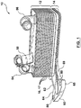
- Heat exchanger module 10 is comprised of a heat exchanger 12 fixedly attached to an adapter module 14.
- Heat exchanger 12 is generally in the form of a nested, dished-plate heat exchanger, as is known in the art, and is comprised of a plurality of stamped heat exchanger plates 16, 17 disposed in alternatingly stacked, brazed relation to one another to form a heat exchanger core with alternating first and second fluid flow passages 20, 22 formed between the stacked plates 16, 17.
- the stamped heat exchange plates 16, 17 each comprise a generally planar base portion 24 surrounded on all sides by a sloping edge wall 26.
- the heat exchange plates 16, 17 are stacked one on top of another with their edge walls 26 in nested, sealed engagement.
- Each heat exchange plate 16, 17 is provided with four holes 28, 30, 32, 34 near its four corners, each of which serves as an inlet hole or an outlet hole for a heat exchange fluid as required by the particular application.
- Two holes 28, 30 are raised with respect to the base portion 24 of the plate 16 while the other two holes 32, 34 are formed in and are co-planar with the base portion 24.
- the raised holes 28, 30 in one plate 16 align with and seal against the flat or co-planar holes 32, 34 of the adjacent plate 17 thereby spacing apart the heat exchange plates 16, 17 and defining the alternating the first and second fluid passages 20, 22.
- Turbulizers 35 can be positioned between each of the plates 16, 17 in each of the first and second fluid passages 20, 22 to improve heat transfer, as is known in the art.
- the plates 16, 17 may themselves may be formed with heat transfer augmentation features, such as ribs and/or dimples formed in the planar base portion of the plates 16, 17, as is known in the art.
- first manifolds 36 i.e. an inlet manifold and an outlet manifold
- second manifolds 38 i.e. an inlet manifold and an outlet manifold
- fluid passages 22 for the flow of a second fluid through the heat exchanger 12.
- the heat exchanger module 10 is intended to be used as an oil heat exchanger (i.e. a transmission oil cooler or TOC)
- one of the first and second fluids can be oil while the other fluid can be a standard, known liquid for cooling (or heating) oil.
- Top and bottom or end plates 40, 42 enclose the stack of heat exchange plates 16, 17 to form the heat exchanger 12.
- the end plates 40, 42 are designed with a particular number of conduit openings, each in fluid communication with one of the pairs of first and second fluid manifolds 36, 38 for the inlet and outlet of the first and the second fluids into and out of the heat exchanger 12.
- end plate 40 has two conduit openings 46, 48 formed therein, while end plate 42 has four openings 28, 30 ,32 ,34 (two of which are closed/sealed by adapter module 14) and generally has the same form as heat exchanger plates 16, 17 except that it may be slightly thicker than plates 16, 17.
- inlet/outlet fittings 54, 56 are fixedly attached or brazed to conduit openings 46, 48 in the end plate 40 by means of a shim plate 43.
- Top or end plate 40 can also be provided with additional fittings or mounting brackets 58, as required, which fittings or mounting brackets 58 can be brazed to end plate 40 by means of shim plate 43.
- Heat exchangers of the type described above are generally known in the art and, for instance, described in United States Patent No. 7,717,164 . Furthermore, the above-described heat exchanger 12 has been described for illustrative purposes and it will be understood that any suitable heat exchanger, as known in the art, may be used in the heat exchanger module 10 of the present disclosure.
- adapter module 14 is comprised of an adapter plate 60 and a shim plate 62.
- Shim plate 62 is a relatively thin, soft braze clad aluminum sheet which allows the adapter plate 60 to be brazed directly to the end plate or bottom plate 42 of the heat exchanger 12.
- the adapter plate 60 is typically machined aluminum and is substantially thicker than shim plate 62 and is also substantially thicker than heat exchange plates 16, 17.
- Adapter plate 60 has a first surface 64 that, together with shim plate 62, is brazed to one end, e.g. the bottom, of heat exchanger 12.
- heat exchanger 12 has a "footprint" corresponding to the area defined by the base portion 24 of the stacked heat exchange plates 16, 17, the adapter module 14 being fixedly attached to the heat exchanger 12 within the footprint area of the heat exchanger 12.
- the adapter module 14 has at least a portion that extends beyond the footprint of the heat exchanger 12, as will be described in further detail below.
- Adapter plate 60 further defines a trough portion 66 in the first surface 64 thereof which, in combination with the shim plate 62, defines a fluid transfer channel 68.
- Fluid transfer channel 68 has one end that communicates with one of the fluid manifolds 38 in the heat exchanger via a conduit opening 70 in shim plate 62 positioned within the footprint of heat exchanger 12, and another end that extends away from the heat exchanger in an extension portion or extension arm 69 of the adapter module 14.
- Trough portion 66 has a fluid port 72 formed at the opposite end of the trough portion (i.e.
- Adapter plate 60 has another fluid opening or fluid port 76 formed therein which is aligned with a corresponding opening 78 formed in shim plate 62. Fluid port 76 provides another direct fluid connection between one of the manifolds 38 in the heat exchanger 12 and a corresponding fluid port in the component housing. Accordingly, one of the fluids flowing through the heat exchanger will ultimately enter and exit the heat exchanger 12 through the adapter module 14.
- the adapter plate 60 also has a plurality of bores 80 formed therein, each aligned with a respective bore or mounting hole provided on the component housing for receiving a fastening device (i.e. a bolt), to secure the heat exchanger module 10 to the housing.
- a fastening device i.e. a bolt
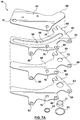
- FIG. 7 shows the heat exchanger module 10 mounted directly to the exterior of an illustrative embodiment of a transmission housing 11. Therefore, in operation wherein the heat exchanger module 10 is a transmission oil cooler (TOC) mounted directly to the housing of a transmission 11, the second fluid would be transmission oil that would exit the transmission housing and enter the heat exchanger module 10 through a fluid port on the transmission housing coupled directly to fluid port 76 in adapter plate 60. The oil would enter the heat exchanger via opening 78 in the shim plate 62 and be distributed via inlet manifold 38 through fluid passages 22 to outlet manifold 38.
- TOC transmission oil cooler
- the transmission oil would then exit the heat exchanger 12 and enter the adapter module 14 through fluid port 70 in the shim plate 62, travel through fluid transfer channel 68 in the adapter module 14 (or trough portion 66 in the adapter plate 60) and enter the transmission through the outboard fluid port 72 on the adapter module 14, i.e. the fluid port that is outside the footprint of the heat exchanger 12 and is not in direct connection to one of the inlet/outlet manifold ports of the heat exchanger 12.
- a suitable fluid for cooling (or heating) the transmission oil would also flow through the heat exchanger 12 through inlet and outlets 56, 58 coupled to the corresponding inlet and outlet manifolds 36 in a direction generally opposite to the flow of the transmission oil.
- fluid transfer channel 68 and fluid port 72 provides for an indirect fluid connection between a fluid port located on the second surface of the adapter module 14 and one of the fluid manifolds within the heat exchanger since fluid port is at least partially outside the footprint of the heat exchanger 12.
- the adapter module 14 is shown as being a relatively flat structure wherein the plurality of bores 80 and the fluid ports are located generally in the same plane, it will be understood that the adapter module 14 can be modified, based on the particular application, to fit the outer surface of the automobile component housing to which it is intended to be fixed. More specifically, the extension portion or extension arm 69 of the adapter plate 60 can be sized and angled as needed to ensure that the adapter module 14 extends to the required location on the component housing to allow for the direct connection between the fluid ports 72, 76 (for example) on the adapter module 14 and the corresponding fluid ports on the component housing. Accordingly, the specific shape and/or size of the adapter module 14 is somewhat dependent upon the structure and corresponding mating surface(s) provided on the component housing.
- the oil ports are typically spaced apart from each other over an area that is generally larger than the "footprint" of conventional heat exchangers or oil coolers traditionally used for this purpose.
- the exemplary embodiment of the heat exchanger module 10 described above addresses this issue by brazing the heat exchanger directly to the adapter module 14 provided with the extension portion 69 that allows for "outboard" fluid connections.
- the adapter module 14 described above is generally a flat structure, it will be understood that the adapter module 14 can also be curved to accommodate a curved outer surface of the housing. As well, the adapter module 14 can be formed with projections and/or protrusions extending from the second surface thereof to provide various contact points between the adapter module 14 and various surfaces on the outer housing.
- the adapter plate 60 does not need to cover the entire "footprint” or base area of the heat exchanger 12, therefore the bottom or end surface of heat exchanger module 10 may be a tiered or multi-level surface. In other embodiments (as shown in Figure 3A ), the adapter plate 60 may cover the entire "footprint" or base area of the heat exchanger 12, the bottom surface thereof being formed as a multi-level surface.
- FIG. 2 , 4 and 6 the second surface or mounting interface 65 of the adapter module 14 with fluid ports 72, 76 is shown in further detail.
- a sealing groove 82 is provided around each fluid port 72, 76 for receiving a seal or sealing means 83, such as an o-ring or any other suitable means known in the art.
- the sealing means 83 provides for a fluid tight connection between the heat exchanger module 10 and the housing of the automobile system component to which it is fixed, such as the transmission housing.
- adapter module 14 described above and shown in the drawings has only one fluid channel 68 and two fluid ports 72, 76, it will be understood that the adapter module can be modified to include additional fluid channels and/or fluid ports depending upon the particular application. As well, the adapter module can be modified so as to house additional components such as, for example, one or more control valve(s) (i.e. thermal bypass valve(s)) or filters.
- control valve(s) i.e. thermal bypass valve(s)
- filters filters.
- the heat exchanger module 10 described above offers both a reduction in overall component height and weight as compared to various other heat exchanger mounting structures. More specifically, as mentioned above, the adapter module 14 is brazed directly to the bottom or end plate 42 of heat exchanger 12 without the use of a conventional heat exchanger base plate or mounting plate thereby decreasing the overall package height and weight of the heat exchanger module 10. Manufacturing costs may also be reduced due to the elimination of the conventional base plate or mounting plate.
- the adapter module incorporates fluid transfer channel(s) and fluid ports, seals and attaching holes all formed therein, the use of a secondary plastic or heavy-duty cast or moulded adapter structure typically used for mounting a heat exchanger to an automobile system component is not required which also reduces the overall package height and weight of the component. Furthermore, by having an adapter module 14 that extends beyond the footprint of the heat exchanger imparts a degree of flexibility or adjustability to the heat exchanger module 10 since fluid ports and/or fluid connection points can be positioned outside the footprint of the heat exchanger.
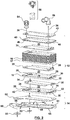
- FIG. 7A illustrates an alternate embodiment or variation of the adapter module 14 described above wherein the adapter module 14 is comprised of a series of layered plates. More specifically, rather than being formed of a single adapter plate 60 and a corresponding shim plate 62, the adapter module 14 in this embodiment is comprised of an adapter plate or channel plate 60 that is sandwiched between shim plate 62 and base plate 63, the base plate 63 being attached to the second or bottom surface of the adapter or channel plate 60 either directly or by means of an intermediate shim plate 65.
- the intermediate shim plate 65 mimics the shape of the adapter plate 60 and the base plate 63 with all the same corresponding openings formed therein and serves to braze the two together.
- the adapter plate 60 is formed with a trough portion 66 in the form of a cut-out, the shim plate 62, adapter plate 60 and base plate 63 together forming the fluid transfer channel 68.
- the layered plate structure of the adapter model 14 shown in Figure 7A may offer manufacturing advantages and/or cost savings over the embodiment shown in Figures 1-7 since the adapter module 14 is comprised of a series of stamped or formed plates rather than a more complex machined singular or unitary adapter plate.
- the heat exchanger 112 comprises a base plate 184 fixedly attached to one end thereof.
- the base plate 184 may be a stamped plate that is substantially thicker than heat exchanger plates 116, 117.
- the base plate 184 is typically brazed directly to the end of the heat exchanger 112 or is brazed to the heat exchanger 112 by means of an intermediate shim plate (not shown).
- Adapter module 114 is a fully enclosed module with fluid transfer channel 168 formed therein.
- the adapter module 114 has a first set of bores 181 for aligning with corresponding bores provided in the base plate 184 and a second set of bores 180 for aligning with corresponding bores on the housing of the automobile system component.
- both the first surface and the second surface 164, 165 of the adapter module 114 are provided with sealing grooves 182 (first surface grooves no shown) around each of the fluid ports or conduit openings 172, 176 to provide seals (i.e. o-rings) between the two separate mounting interfaces.
- adapter module 114 described above and shown in the related drawings has only one fluid channel 168 and two fluid ports 172, 176, it will be understood that the adapter module 114 can be modified to include additional fluid channels and/or fluid ports depending upon the particular application.
- the heat exchanger module 200 is comprised of a heat exchanger 212 and an adapter module 214, wherein the adapter module 214 is comprised of an adapter plate 260 and mounting plate 290.
- Adapter plate 260 has a base in the form of a shim plate 292 that, in the illustrated embodiment, generally corresponds in size and shape to the footprint of the heat exchanger 212, although various other configurations may be used.
- the shim plate 292 is provided with fluid openings therein (not shown) for allowing fluid communication between the fluid manifolds 236, 238 in the heat exchanger 212 and the various components and/or adapters 294.
- the various components and/or adapters 294 that provide fluid connections to the automobile system component are positioned on shim plate 292 and may be oriented to allow for direct connection between the component and/or adapter 294 and the corresponding fluid port on the component housing.
- the adapters 294 would have to be structured and arranged on shim plate 292 to provide fluid openings at their free end that are vertically or axially aligned with the corresponding fluid ports on the component housing. Otherwise, additional connectors and/or tubing would be required to connect the fluid ports on the component housing to the corresponding fluid openings provided at the free ends of the adapters 294.
- the adapters 294 are arranged for direct connection to the fluid ports, by directly brazing the components/adapters 294 to the shim plate 292 and heat exchanger 212, only one set of seals is required between the adapter plate 260 and automobile system component housing interface(s).
- adapters 294 shown in Figures 10 and 11 only extend slightly beyond the footprint of the heat exchanger 212, it will be understood that the size and shape of the adapters 294 can be varied based on the particular application to ensure that fluid ports/connections are provided at the appropriate locations.
- additional tubing and/or connectors may be used to connect to the fluid ports on the component housing to the corresponding fluid ports/openings of the corresponding component/adapter 294.
- mounting plate 290 is provided.
- Mounting plate 290 is brazed to shim plate 292 and is configured to fit between the various components/adapters 294 that are also brazed to shim plate.
- Mounting plate 290 is provided with a plurality of bores 296 for aligning with corresponding mounting holes on the component housing.
- Mounting plate 290 can be adapted and configured so that the bores 296 are provided in various planes, some of which may have various axial orientations thereby providing a great deal of flexibility to adapt the heat exchanger module 200 to various component housings.
- the exemplary embodiment described above in connection with Figures 10 and 11 is particularly suited for applications wherein the automobile system component is a transmission and the heat exchanger is a transmission oil cooler (TOC) since the fluid connections/adapters 294 are brazed directly to the base of the heat exchanger 212 by means of shim plate 292 without the use of a conventional, stamped heat exchanger base plate or mounting plate. Since the cyclic loads/pressures associated with the transmission are somewhat less than those associated with other components (i.e. an engine housing) the added structural rigidity provided by a conventional base plate or mounting plate is not necessarily required.
- TOC transmission oil cooler
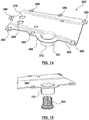
- FIG. 12-15 Another exemplary embodiment of the heat exchanger module 300 according to the present disclosure is shown in Figures 12-15 and is described in further detail below wherein similar reference numerals increased by a factor of 300 have been used to identify similar features.
- heat exchanger module 300 is comprised of a heat exchanger 312 fixedly attached to an adapter module 314.
- the heat exchanger module 300 is particularly suited for direct mounting to the exterior of an automobile engine housing (or casing) and, therefore, functions as an engine oil cooler (EOC).
- EOC engine oil cooler
- the heat exchanger module 300 can be adapted for other purposes or applications as discussed above in connection with the other exemplary embodiments disclosed herein.
- the adapter module 314 is a layered plate structure and is comprised of a first adapter plate 360 that is brazed directly to the base of the heat exchanger 312 by means of a first shim plate 362.
- a second adapter plate 360' is brazed directly to the opposite surface of the first adapter plate 360 by means of a second shim plate 362'.
- the first adapter plate 360 is essentially sandwiched between first and second shim plates 362, 362'. All of the plates 362, 360, 362', 360' used to form adapter module 314 are relatively simple in structure and relatively easy to manufacture, as compared to some known, conventional complex casting adapter structures.
- First adapter plate 360 is a relatively thick, machined or formed aluminum plate that offers the required structural rigidity for directly mounting the heat exchanger module 300 to the engine housing, while shim plates 362, 362' are substantially thinner than adapter plate 360 and are made of braze clad aluminum.
- the first adapter plate 360 includes trough portion 366 in the form of a cut-out within the first adapter plate 360. The cut-out or trough portion 366 extends into the extension arm or extension portion 369 of the adapter module 314.
- the cut-out or trough portion 366 in the first adapter plate 360, together with the first and second shim plates 362, 362' form the at least one fluid transfer channel 368 in the adapter module 314 as the shim plates 362, 362' essentially enclose the cut-out or trough portion 366 to form the fluid transfer channel 368.
- one end of fluid transfer channel 368 communicates with one of the fluid manifolds in heat exchanger 312 (i.e. the oil inlet manifold, for example) via a corresponding opening (not shown) formed in the first shim plate 362.
- the other end of the fluid transfer channel 368 extends into the extension portion 369 of the adapter module 314 and is adapted for fluid connection to a corresponding fluid port on the automobile system component housing (i.e. the engine oil outlet on the engine housing).
- the extension portion 369 therefore providing an indirect fluid connection (i.e. at least partially outside the boundary of or the footprint of the heat exchanger core) to one of the fluid manifolds within the heat exchanger.
- First adapter plate 360 is also provided with two additional fluid openings 304, 306 each of which is in fluid communication with separate ones of the fluid manifolds in heat exchanger 312.
- fluid opening 306 communicates with the oil outlet manifold of heat exchanger 312, via a corresponding opening (not shown) formed in the first shim plate 362 and is coupled to the corresponding fluid port (i.e. the oil inlet port) on the engine housing via corresponding openings in the both the second shim plate 362' and second adapter plate 360' (see opening 376).
- Fluid opening 304 communicates with the coolant inlet manifold from heat exchanger 312 via a corresponding opening (not shown) formed in the first shim plate 362 and is coupled to a corresponding fluid port (i.e. the coolant inlet port) on the engine housing via corresponding openings in the second shim plate 362' and the second adapter plate 360' (see opening 308).
- the second adapter plate 360' is generally thinner than the first adapter plate 360 and generally corresponds to the shape of the first adapter plate 360.
- the second adapter plate 360' includes at least one cylindrical projection 321 that extends from the bottom or second surface 365 of the second adapter plate 360', wherein the open end of the cylindrical projection 321 serves as outboard fluid port 372 of the adapter module 314.
- the cylindrical projection 321 is adapted to house a valve component 323, such as an anti-drain valve or a thermal bypass valve, to control the flow of one of the fluids (i.e. engine oil) to the heat exchanger 312.
- the valve component 323 may be threadingly engaged in the cylindrical projection 321 or housed within the cylindrical projection in any suitable manner as known in the art.
- valve component 323 may be press-fit into the cylindrical projection 321 and secured or clamped in place between the extended shim plate 362 and the cylindrical projection 321 by means of indentations that are formed in the lower edge of the cylindrical projection 321 after assembly.
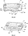
- the cylindrical projection 321 is formed directly within the second adapter plate 360' (as shown in Figure 14 ) and in other embodiments the cylindrical projection 321 can be formed from a separate component that is brazed (by means of a shim ring 321') or otherwise attached to the outer surface of the second adapter plate 360' in alignment with a corresponding opening 372' formed in the adapter plate 360' to form the outboard fluid port 372 as shown, for example, in Figure 16 .
- the first and second adapter plates 360, 360' are also both provided with a plurality of bores 380 around the perimeter thereof, each of which align with corresponding openings in the automobile system component housing (i.e. the engine housing) and are adapted for receiving a fastening device (such as a bolt) for securing the heat exchanger module 300 to the component housing.
- a fastening device such as a bolt
- the adapter module 314 described above and shown in the related drawings has only one fluid transfer channel 368 and has three fluid ports 372, 376, 308 formed on its bottom or mounting surface 365, it will be understood that the adapter module 314 can be modified to include additional fluid channels and/or a different arrangement of fluid ports depending upon the particular application. As well, the adapter module 314 can be further modified so as to house additional components such as, for example, additional valve components and/or filters.
- the adapter module 314 may be modified and/or adapted for use for other applications.
- the first adapter plate 360 is a relatively thick plate and provides a certain degree of structural rigidity necessary for mounting heat exchangers to engine housings.
- the thickness and/or material of the plate could be varied in instances where the same degree of structural rigidity is not necessarily required.
- Heat exchanger module 400 is similar in structure to the heat exchanger module 300 described above in connection with Figures 12-16 in that it too has a generally layered plate structure and is particularly suited for direct mounting to the exterior of an automobile engine housing (or casing) and, therefore also functions as an engine oil cooler (EOC) in the subject embodiment.
- EOC engine oil cooler
- the heat exchanger module 400 can be adapted for other purposes or applications in accordance with the scope of the present disclosure.
- heat exchanger module 400 is comprised of heat exchanger 412 that is secured/attached to adapter module 414.
- the adapter module 414 is a layered plate structure comprising a first adapter plate or channel plate 460 and a second adapter plate or base plate 460'.
- the first adapter plate or channel plate 460 is brazed to an end of the heat exchanger 412 by means of a first shim plate or extended shim plate 462 (since it extends beyond the footprint of the heat exchanger 412 to enclose the trough portion 466).
- the second adapter plate 460' is brazed to the second or bottom surface of the first adapter plate 460 either directly or by means of a second or intermediate shim plate 462'.
- the first adapter plate or channel plate 460 is a relatively thick machined, stamped or formed aluminum plate.
- the second adapter plate 460' is a similarly formed plate although the second adapter plate or base plate 460' may not be as thick as the first adapter plate 460.
- the first and second adapter plates 460, 460' offer the structural rigidity required in order to directly mount the heat exchanger modules 400 to the engine housing.
- the first and second shim plates 462, 462' are substantially thinner than the adapter plates 460, 460', as is generally understood in the art and are typically made of braze clad aluminum for brazing the first and second adapter plates 460, 460' together in their layered relationship to form the adapter module 400.
- the first adapter plate or channel plate 460 is larger than the footprint of the heat exchanger 412 so as to provide an extension arm or extension portion 469 that extends beyond the perimeter of the heat exchanger core.
- a trough portion 466 in the form of a cut-out, is formed in the first adapter plate or channel plate 460 and extends into the extension arm or extension portion 466 of the first adapter plate 460.
- the first adapter or channel plate 460 together with the second adapter plate or base plate 460' and first shim plate 462 form a first fluid transfer channel 468 as the first shim plate 462 and the second adapter plate 460' essentially enclose the cut-out or trough portion 466 in the first adapter plate 460 to form the first fluid transfer channel 468.
- one end of the first fluid transfer channel 468 communicates with one of the inlet/outlet manifolds of the heat exchanger 412.
- the first fluid transfer channel 468 communicates with the oil inlet manifold to the heat exchanger 412.
- the second adapter plate or base plate 460' generally has the same shape as the first adapter plate 460 and has a primary or main fluid opening 461 formed therein which communicates directly with the portion of the first fluid transfer channel 468 that extends into the extension portion 466 of the adapter module 414.
- the main fluid opening 461 is fitted with a separate cylindrical projection 421 that is attached or otherwise fixed to the second adapter plate 460' with the cylindrical projection 421 extending away from the bottom thereof.
- the free end 472 of the cylindrical projection 421 is adapted to fit directly with or mount directly to the engine oil outlet on the engine housing.
- a valve component 423 in the form of an anti-drain valve fits within the cylindrical projection 421 which serves as the oil inlet to the adapter module 414 in order to control the flow fluid into/out of the adapter module 414. More specifically, when the valve component 423 is in the form of an anti-drain valve, the valve component 423 is intended to allow for one-way flow, against gravity, into the adapter module 414 through fluid opening 472. Accordingly, the anti-drain valve serves to prevent the fluid from flowing out of the adapter module 414 through the same fluid opening 472, i.e. the oil inlet into the adapter module 414, with gravity.
- the first shim plate 462 is positioned on top of the first adapter plate 460 and generally has the same shape as the bottom of the heat exchanger 414 but has a portion 469' that extends beyond the footprint of the heat exchanger core in order to enclose the trough or cut-out portion 466 to form the first fluid transfer channel 468. Accordingly, the first shim plate 462 can also be referred to as an extended shim plate since it extends beyond the boundary of or the footprint of the heat exchanger.
- the first shim plate is also provided with a fluid opening 465 for providing direct fluid communication between the oil inlet manifold in heat exchanger 414 and the fluid transfer channel 468.
- the first shim plate 462, the first adapter plate 460, the intermediate shim plate 426' (if used) and the second adapter plate 460' are all also provided with at least two additional fluid openings 404, 406 which all align with each other when the plates are arranged in their stacked or layered arrangement.
- the aligned fluid openings 404, 406 provide for fluid communication between respective inlet/outlet manifolds associated with heat exchanger 414.
- fluid opening 406 is in direct communication with the oil outlet manifold of heat exchanger 412 while fluid opening 404 is in direct communication with the coolant inlet manifold in the heat exchanger 414.
- the fluid openings 471, 406, 404 on the bottom or interface surface of the adapter module 414 allows for fluid communication between the heat exchanger 412 and the engine to allow for engine oil to enter/exit the heat exchanger module 400 and be returned to the engine housing and also allows for engine coolant to exit the engine housing and enter the heat exchanger module 400 before being directed elsewhere in the system via the coolant outlet located on the top of the heat exchanger 412.
- the adapter module 414 further provides for both engine oil and coolant bypass channels to allow engine oil that does not enter the heat exchanger 412 to drain back into the engine housing and to allow engine coolant to bypass the heat exchanger 412 and be directed directly to the outlet manifold of the heat exchanger 412.
- the heat exchanger module 400 can be tuned or adjusted to changes in fluid pressure within the system.
- the adapter module 404 is provided with a first bypass opening 481 in fluid communication with the first fluid transfer channel 468 (as shown more clearly in Figure 20 ).
- the first bypass opening 481 is therefore formed in the second adapter plate or base plate 460' spaced apart from the main fluid opening 461 and in-line with the opening to the oil inlet manifold of heat exchanger 412.
- the first bypass opening 481 is therefore in communication with the first fluid transfer channel 468 directly opposite to the oil inlet manifold of the heat exchanger 412.
- the bypass opening 481 is arranged in vertical alignment with the oil inlet opening on the engine housing.
- the adapter module 414 is provided with a second fluid transfer channel 483 (see Figure 21 ) in order to provide fluid communication between the inlet and outlet manifolds for the second fluid flowing through the heat exchanger 412 which, in the illustrated embodiment, is engine coolant.
- the second fluid transfer channel 483 allows engine coolant to bypass the heat exchanger 412 and instead be directed directly to the outlet manifold of the heat exchanger 412 (without having to flow through the heat transfer fluid passageways formed therein) and out of the heat exchanger module 412 through the outlet fitting located at the top of the heat exchanger 412.
- the second fluid transfer channel 483 provides a form of bypass channel permitting the coolant to exit the heat exchanger module 412 and be directed elsewhere in the system without having to flow through the heat exchanger 412.
- the second fluid transfer channel 483 is formed by a second trough portion 485 formed in the first or extended shim plate 462 with the second trough portion 485 extending from the fluid opening 404 to the opposed end of the shim plate 462, the opposed end of the second trough portion 485 therefore being aligned with the coolant outlet manifold of heat exchanger 412.
- the adapter module 414 not only provides for fluid communication between the automobile system component housing (i.e. the engine housing) and the heat exchanger 412, but also provides for fluid communication between a pair of corresponding inlet/outlet manifolds for one of the heat exchange fluids flowing through the heat exchanger 412.
- the adapter module 400 further comprises a gasket plate 487 affixed to the bottom surface of the second adapter plate or base plate 460'.
- the gasket plate 487 is formed with sealing members 488 that essentially encircle or surround the fluid passageways and/or openings provided at the interface surface between the engine housing and the heat exchanger module 400.
- the adapter module 400 is provided with a plurality of openings 480 formed at spaced apart intervals around the perimeter of the adapter module 414 each for receiving a fastening device for securing the heat exchanger module 400 to the automobile system component housing. Accordingly, it will be understood that the openings 480 are formed by corresponding, axially aligned openings in each of the plates that make up the layered plate structure of the adapter module 414.
- engine oil exits the engine housing and enters the adapter module 414 via fluid opening 471 through anti-drain valve 423.
- the engine oil then travels through the first fluid transfer channel 468 and either enters the heat exchanger 412 oil inlet manifold through the corresponding opening formed in the first shim plate 462 or exits the adapter module 414 through the bypass opening and is returned to the engine housing through the oil inlet opening formed in the engine housing.
- the oil travels through the heat exchanger 412 and exits the heat exchanger 412 through the oil outlet manifold on the bottom of the heat exchanger and is returned to the engine housing through the engine oil inlet opening provided on the housing via the adapter module 414.
- the second fluid i.e.
- fluid pressure drops within the heat exchanger module 400 can be tuned to appropriate levels based on the particular application or system requirements to ensure that heat transfer performance associated with the heat exchanger module is not adversely affected by changes in fluid pressure.
Description
- This application claims the benefit of and priority to International Application No.
PCT/CA2012/050263, filed on April 26, 2012 - The invention relates to heat exchangers adapted for direct mounting to the housing of an automobile system component.
- Plate-type heat exchangers comprising a plurality of stacked heat exchanger plates are known for a variety of purposes, including heat exchange between oil and a heat exchange fluid. A known way of mounting a stacked plate heat exchanger is to mount a planar, stamped base plate at one end of the stack, for example, the bottom end. The base plate can be brazed to the heat exchanger with or without the use of a shim plate. In order to incorporate the heat exchanger into an automobile heat exchanger system, for example, the heat exchanger with base plate is then, typically, mounted to a cast or moulded adapter structure which in turn is mounted to the transmission or engine housing, for example, using additional fluid lines and/or connectors. The cast or moulded adapter structure includes mounting holes, fluid transfer channels, fluid fittings, filters, etc. to allow the heat exchanger to be incorporated into the overall heat exchange system. In some instances the cast or moulded adapter structure is made of plastic and in other instances it is a more heavy-duty casting that can be quite complex in structure and costly. In both instances, the adapter structure contributes to the overall height and weight of the heat exchanger component as well as to the overall manufacturing costs.
- In the field of automotive heat exchanger manufacture, weight limitations as well as space limitations are becoming increasingly restrictive. Accordingly, efforts are constantly being made to reduce component weight as well as component height and/or size. Efforts are also being made to reduce the complexity and increase the adaptability and/or flexibility of components to facilitate assembly and mounting of the component within the overall system and in an effort to reduce overall manufacturing and/or assembly costs. For instance, reducing the overall number of components or component interfaces that result from mounting or integrating a component within an overall system reduces the number of potential leakage points thereby reducing testing requirements as well as assembly steps. Reducing the complexity of components and reducing the number of more complex fluid connections between components also serves to reduce costs and is, therefore, desirable.
- In automobile heat exchange systems, one manner of accommodating or adjusting to space limitations is to consider mounting heat exchangers directly to a related automotive system component without the use of an intervening adapter or mounting structure. For instance, it is not uncommon for an engine oil cooler (EOC) to be mounted directly to the exterior of the automobile engine housing. An example of an EOC mounted directly to the exterior of the engine housing is shown in
JP2011149015 -
US 5964283 A discloses a heat exchanger module according to the preamble of claim 1. - The structure of the engine housing is, generally, somewhat conducive to mounting a heat exchanger directly to the exterior of the engine housing. The area of the cylinder head generally provides a flat, machined recess to which the heat exchanger can be bolted while having direct access to the oil inlet and return passages. However, by bolting the heat exchanger to the cylinder head in this area the heat exchanger must bridge or span the machined recess and must therefore be relatively stiff to minimize deflections from the relatively high cyclic pressure loads of the oil system inherent to the engine, which tend to be amplified depending upon the exact distance bridged by the heat exchanger. Accordingly, specific structural requirements need to be addressed when mounting a heat exchanger directly to the engine housing, while still keeping overall height and space limitations in mind.
- While directly mounting heat exchangers to the exterior of the engine housing requires that a certain degree of structural rigidity be met, the structure of the housings of other automobile system components also present challenges related to the direct mounting of heat exchangers to the component housing. For instance, in the case of transmission housings, the housings are generally curved and are much larger in size which makes it difficult to provide a wide, generally flat area/recess for mounting a heat exchanger without intruding vertically into the internal parts of the transmission. Furthermore, transmission oil supply feed lines and/or oil ports are generally spaced farther away from each other and outside the footprint area of conventional heat exchangers used for this purpose. As well, the exact location/position of the oil ports is often variable. These factors contribute to difficulties associated with direct mounting a heat exchanger, such as a transmission oil cooler (TOC), to the exterior of the transmission housing.
- Accordingly, there is a need for a heat exchanger with an improved mounting arrangement which allows for the direct mounting of the heat exchanger to the housing of an automobile system component.
- According to the invention, there is provided a heat exchanger module for mounting directly to the outer surface of a housing of an automobile system component, the heat exchanger module comprising a heat exchanger comprising a plurality of stacked heat exchange plates defining alternating first and second fluid paths through said heat exchanger, the heat exchanger having a footprint corresponding to the area defined by the stack of heat exchange plates; a pair of first fluid manifolds extending through the heat exchanger and coupled to one another by the first fluid paths, the pair of first fluid manifolds comprising an inlet manifold and an outlet manifold for the flow of a first fluid through said heat exchanger; a pair of second fluid manifolds extending through the heat exchanger and coupled to one another by the second fluid paths, the pair of second fluid manifolds comprising an inlet manifold and an outlet manifold for the flow of a second fluid through said heat exchanger; an adapter module having a first surface attached to an end of the heat exchanger and a second surface opposite to said first surface and adapted for face-to-face contact with an interface surface on the outer surface of the housing of the automobile system component, the adapter module comprising a first fluid transfer channel formed in the adapter module, the first fluid transfer channel being in direct fluid communication with one of the inlet and outlet manifolds of one of said pairs of fluid manifolds; a first port formed in the second surface of said adapter module, the first port being in fluid communication with the first fluid transfer channel; a second port formed in the second surface of said adapter module, the second port being in fluid communication with the other one of the inlet and outlet manifolds of said pair of fluid manifolds; and a third port formed in the second surface of said adapter module, the third port being in fluid communication with the first fluid transfer channel; wherein the first fluid transfer channel provides fluid communication between inlet and outlet ports formed in the interface surface of the housing of the automobile system component and an inlet manifold of said heat exchanger.
- Exemplary embodiments of the present disclosure will now be described, by way of example, with reference to the accompanying drawings, in which:
-
FIGURE 1 is a perspective view of a heat exchanger module according to an exemplary embodiment of the present disclosure; -
FIGURE 2 is an exploded view of the heat exchanger module ofFigure 1 ; -
FIGURE 3A is a perspective view of an adapter plate that forms part of an adapter module of the heat exchange module as shown inFigure 2 ; -
FIGURE 3B is a perspective view of an alternate embodiment of the adapter plate ofFigure 3A ; -
FIGURE 4 is a bottom view of the heat exchanger module ofFigure 1 ; -
FIGURE 5 is a perspective view of a shim plate that forms part of the adapter module of the heat exchanger module ofFigure 1 ; -
FIGURE 6 is a view along section line 5-5 ofFigure 4 ; -
FIGURE 7 is a perspective view of the heat exchanger module ofFigure 1 mounted to the exterior of an, exemplary, transmission housing; -
FIGURE 7A is an exploded view of an alternate embodiment of the adapter module of the heat exchanger module ofFigure 1 ; -
FIGURE 8 is a perspective view of a heat exchanger module according to another exemplary embodiment of the present disclosure; -
FIGURE 9 is a bottom view of the structure ofFigure 8 ; -
FIGURE 10 is a perspective view of a heat exchanger module according to another exemplary embodiment of the present disclosure shown mounted directly on the housing of an automobile system component; -
FIGURE 11 is a bottom perspective view of the heat exchanger module ofFigure 10 ; -
FIGURE 12 a perspective view of a heat exchanger module according to yet another exemplary embodiment of the present disclosure; -
FIGURE 13 is a perspective view of a portion of the adapter module that forms part of the heat exchanger module shown inFigure 12 ; -
FIGURE 14 is a perspective view of a portion of the adapter module ofFigure 13 ; -
FIGURE 15 is an exploded view of a portion of the adapter module ofFigure 12 ; -
FIGURE 16 is an exploded, perspective view of the underside of a portion of an alternate embodiment of the adapter module ofFigure 14 ; -
FIGURE 17 is a perspective view of a heat exchanger module according to yet another exemplary embodiment of the present disclosure; -
FIGURE 18 is an exploded, perspective view of the heat exchanger module shown inFigure 17 ; -
FIGURE 19 is a bottom perspective view of the heat exchanger module ofFigure 17 ; -
FIGURE 20 is an exploded view of a portion of the heat exchanger module ofFigure 17 illustrating the oil side of the adapter module; and -
FIGURE 21 is an exploded view of a portion of the heat exchanger module ofFigure 17 illustrating the coolant side of the adapter module. - Referring now to
Figure 1 , there is shown an exemplary embodiment of aheat exchanger module 10 according to the present disclosure.Heat exchanger module 10 is comprised of aheat exchanger 12 fixedly attached to anadapter module 14.Heat exchanger 12 is generally in the form of a nested, dished-plate heat exchanger, as is known in the art, and is comprised of a plurality of stampedheat exchanger plates fluid flow passages stacked plates - Referring now to
Figure 2 , an exploded view of theheat exchanger module 10 is shown. As illustrated, the stampedheat exchange plates planar base portion 24 surrounded on all sides by a slopingedge wall 26. Theheat exchange plates edge walls 26 in nested, sealed engagement. Eachheat exchange plate holes holes base portion 24 of theplate 16 while the other twoholes base portion 24. The raised holes 28, 30 in oneplate 16 align with and seal against the flat orco-planar holes adjacent plate 17 thereby spacing apart theheat exchange plates fluid passages Turbulizers 35 can be positioned between each of theplates fluid passages individual turbulizers 35 positioned in each of thefluid passages plates plates holes stacked plates fluid passages 20 for the flow of a first fluid through the heat exchanger and form a pair of second manifolds 38 (i.e. an inlet manifold and an outlet manifold) coupled to one another byfluid passages 22 for the flow of a second fluid through theheat exchanger 12. If, for example, theheat exchanger module 10 is intended to be used as an oil heat exchanger (i.e. a transmission oil cooler or TOC), one of the first and second fluids can be oil while the other fluid can be a standard, known liquid for cooling (or heating) oil. - Top and bottom or
end plates heat exchange plates heat exchanger 12. Depending upon the particular application, theend plates second fluid manifolds heat exchanger 12. In the example shown,end plate 40 has twoconduit openings end plate 42 has fouropenings heat exchanger plates plates - In the illustrated embodiment, inlet/
outlet fittings conduit openings end plate 40 by means of ashim plate 43. Top orend plate 40 can also be provided with additional fittings or mountingbrackets 58, as required, which fittings or mountingbrackets 58 can be brazed toend plate 40 by means ofshim plate 43. - Heat exchangers of the type described above are generally known in the art and, for instance, described in United States Patent No.
7,717,164 . Furthermore, the above-describedheat exchanger 12 has been described for illustrative purposes and it will be understood that any suitable heat exchanger, as known in the art, may be used in theheat exchanger module 10 of the present disclosure. - Referring now to
Figures 1 ,3 ,4 and5 , theadapter module 14 according to one exemplary embodiment of the present disclosure will now be described in further detail. In the subject embodiment,adapter module 14 is comprised of anadapter plate 60 and ashim plate 62.Shim plate 62 is a relatively thin, soft braze clad aluminum sheet which allows theadapter plate 60 to be brazed directly to the end plate orbottom plate 42 of theheat exchanger 12. Theadapter plate 60 is typically machined aluminum and is substantially thicker thanshim plate 62 and is also substantially thicker thanheat exchange plates Adapter plate 60 has afirst surface 64 that, together withshim plate 62, is brazed to one end, e.g. the bottom, ofheat exchanger 12. As shown in the drawings,heat exchanger 12 has a "footprint" corresponding to the area defined by thebase portion 24 of the stackedheat exchange plates adapter module 14 being fixedly attached to theheat exchanger 12 within the footprint area of theheat exchanger 12. In the subject embodiment, theadapter module 14 has at least a portion that extends beyond the footprint of theheat exchanger 12, as will be described in further detail below. -
Adapter plate 60 further defines atrough portion 66 in thefirst surface 64 thereof which, in combination with theshim plate 62, defines afluid transfer channel 68.Fluid transfer channel 68 has one end that communicates with one of thefluid manifolds 38 in the heat exchanger via a conduit opening 70 inshim plate 62 positioned within the footprint ofheat exchanger 12, and another end that extends away from the heat exchanger in an extension portion orextension arm 69 of theadapter module 14.Trough portion 66 has afluid port 72 formed at the opposite end of the trough portion (i.e. outboard the footprint of theheat exchanger 12 in theextension portion 69 of the adapter module 14), thefluid port 72 being adapted to fit and be mounted directly to a corresponding fluid port in the housing of an automobile system component (i.e. an oil port on a transmission housing).Adapter plate 60 has another fluid opening orfluid port 76 formed therein which is aligned with acorresponding opening 78 formed inshim plate 62.Fluid port 76 provides another direct fluid connection between one of themanifolds 38 in theheat exchanger 12 and a corresponding fluid port in the component housing. Accordingly, one of the fluids flowing through the heat exchanger will ultimately enter and exit theheat exchanger 12 through theadapter module 14. Theadapter plate 60 also has a plurality ofbores 80 formed therein, each aligned with a respective bore or mounting hole provided on the component housing for receiving a fastening device (i.e. a bolt), to secure theheat exchanger module 10 to the housing. -
Figure 7 shows theheat exchanger module 10 mounted directly to the exterior of an illustrative embodiment of atransmission housing 11. Therefore, in operation wherein theheat exchanger module 10 is a transmission oil cooler (TOC) mounted directly to the housing of atransmission 11, the second fluid would be transmission oil that would exit the transmission housing and enter theheat exchanger module 10 through a fluid port on the transmission housing coupled directly tofluid port 76 inadapter plate 60. The oil would enter the heat exchanger via opening 78 in theshim plate 62 and be distributed viainlet manifold 38 throughfluid passages 22 tooutlet manifold 38. The transmission oil would then exit theheat exchanger 12 and enter theadapter module 14 throughfluid port 70 in theshim plate 62, travel throughfluid transfer channel 68 in the adapter module 14 (ortrough portion 66 in the adapter plate 60) and enter the transmission through theoutboard fluid port 72 on theadapter module 14, i.e. the fluid port that is outside the footprint of theheat exchanger 12 and is not in direct connection to one of the inlet/outlet manifold ports of theheat exchanger 12. A suitable fluid for cooling (or heating) the transmission oil would also flow through theheat exchanger 12 through inlet andoutlets fluid transfer channel 68 andfluid port 72 provides for an indirect fluid connection between a fluid port located on the second surface of theadapter module 14 and one of the fluid manifolds within the heat exchanger since fluid port is at least partially outside the footprint of theheat exchanger 12. - While a particular example of the fluids circuiting through the
heat exchanger 12 has been described, it will be understood that this is not intended to be limiting and that variations depending upon the particular structure of the heat exchanger and/or the associated automobile system component may result in a different fluid pattern/circuit through theheat exchanger module 10 as would be understood by those skilled in the art. - While the
adapter module 14 is shown as being a relatively flat structure wherein the plurality ofbores 80 and the fluid ports are located generally in the same plane, it will be understood that theadapter module 14 can be modified, based on the particular application, to fit the outer surface of the automobile component housing to which it is intended to be fixed. More specifically, the extension portion orextension arm 69 of theadapter plate 60 can be sized and angled as needed to ensure that theadapter module 14 extends to the required location on the component housing to allow for the direct connection between thefluid ports 72, 76 (for example) on theadapter module 14 and the corresponding fluid ports on the component housing. Accordingly, the specific shape and/or size of theadapter module 14 is somewhat dependent upon the structure and corresponding mating surface(s) provided on the component housing. For instance, in the case of a transmission housing, the oil ports are typically spaced apart from each other over an area that is generally larger than the "footprint" of conventional heat exchangers or oil coolers traditionally used for this purpose. The exemplary embodiment of theheat exchanger module 10 described above addresses this issue by brazing the heat exchanger directly to theadapter module 14 provided with theextension portion 69 that allows for "outboard" fluid connections. - Furthermore, while the
adapter module 14 described above is generally a flat structure, it will be understood that theadapter module 14 can also be curved to accommodate a curved outer surface of the housing. As well, theadapter module 14 can be formed with projections and/or protrusions extending from the second surface thereof to provide various contact points between theadapter module 14 and various surfaces on the outer housing. - As shown in
Figure 3B , theadapter plate 60 does not need to cover the entire "footprint" or base area of theheat exchanger 12, therefore the bottom or end surface ofheat exchanger module 10 may be a tiered or multi-level surface. In other embodiments (as shown inFigure 3A ), theadapter plate 60 may cover the entire "footprint" or base area of theheat exchanger 12, the bottom surface thereof being formed as a multi-level surface. - Referring now to
Figures 2 ,4 and6 , the second surface or mountinginterface 65 of theadapter module 14 withfluid ports groove 82 is provided around eachfluid port heat exchanger module 10 and the housing of the automobile system component to which it is fixed, such as the transmission housing. In prior art structures wherein a heat exchanger with a stamped base plate or mounting plate is fixed to a plastic cast or moulded structure which, in turn, is mounted to the automobile system component housing, sealing interfaces are required between both the heat exchanger and the plastic structure, and between the plastic structure and the automobile system component . Accordingly, two independent sets of seals are required giving rise to two potential points of failure/leakage, both requiring testing. In the subject embodiment, only one set of seals is required between theheat exchanger module 10 and the housing of the component to which it is fixed. - While the
adapter module 14 described above and shown in the drawings has only onefluid channel 68 and twofluid ports - It will be understood that the
heat exchanger module 10 described above offers both a reduction in overall component height and weight as compared to various other heat exchanger mounting structures. More specifically, as mentioned above, theadapter module 14 is brazed directly to the bottom orend plate 42 ofheat exchanger 12 without the use of a conventional heat exchanger base plate or mounting plate thereby decreasing the overall package height and weight of theheat exchanger module 10. Manufacturing costs may also be reduced due to the elimination of the conventional base plate or mounting plate. As well, since the adapter module incorporates fluid transfer channel(s) and fluid ports, seals and attaching holes all formed therein, the use of a secondary plastic or heavy-duty cast or moulded adapter structure typically used for mounting a heat exchanger to an automobile system component is not required which also reduces the overall package height and weight of the component. Furthermore, by having anadapter module 14 that extends beyond the footprint of the heat exchanger imparts a degree of flexibility or adjustability to theheat exchanger module 10 since fluid ports and/or fluid connection points can be positioned outside the footprint of the heat exchanger. -
Figure 7A illustrates an alternate embodiment or variation of theadapter module 14 described above wherein theadapter module 14 is comprised of a series of layered plates. More specifically, rather than being formed of asingle adapter plate 60 and acorresponding shim plate 62, theadapter module 14 in this embodiment is comprised of an adapter plate orchannel plate 60 that is sandwiched betweenshim plate 62 andbase plate 63, thebase plate 63 being attached to the second or bottom surface of the adapter orchannel plate 60 either directly or by means of anintermediate shim plate 65. Theintermediate shim plate 65 mimics the shape of theadapter plate 60 and thebase plate 63 with all the same corresponding openings formed therein and serves to braze the two together. In this embodiment, theadapter plate 60 is formed with atrough portion 66 in the form of a cut-out, theshim plate 62,adapter plate 60 andbase plate 63 together forming thefluid transfer channel 68. The layered plate structure of theadapter model 14 shown inFigure 7A may offer manufacturing advantages and/or cost savings over the embodiment shown inFigures 1-7 since theadapter module 14 is comprised of a series of stamped or formed plates rather than a more complex machined singular or unitary adapter plate. - Referring now to
Figures 8 and9 , another exemplary embodiment of theheat exchanger module 100 according the present disclosure will now be described, wherein similar reference numerals, increased by a factor of 100, are used to denote similar features. In the subject embodiment, theheat exchanger 112 comprises abase plate 184 fixedly attached to one end thereof. Thebase plate 184 may be a stamped plate that is substantially thicker thanheat exchanger plates base plate 184 is typically brazed directly to the end of theheat exchanger 112 or is brazed to theheat exchanger 112 by means of an intermediate shim plate (not shown).Adapter module 114 is a fully enclosed module with fluid transfer channel 168 formed therein. In the subject embodiment, theadapter module 114 has a first set ofbores 181 for aligning with corresponding bores provided in thebase plate 184 and a second set ofbores 180 for aligning with corresponding bores on the housing of the automobile system component. As well, in the subject embodiment, both the first surface and thesecond surface adapter module 114 are provided with sealing grooves 182 (first surface grooves no shown) around each of the fluid ports orconduit openings - Once again, while the
adapter module 114 described above and shown in the related drawings has only one fluid channel 168 and twofluid ports adapter module 114 can be modified to include additional fluid channels and/or fluid ports depending upon the particular application. - Referring now to
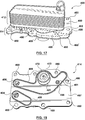
Figures 10 and 11 , another exemplary embodiment of theheat exchanger module 200 according to the present disclosure will now be described, wherein similar reference numerals, increased by a factor of 200, are used to denote similar features. - In particular applications where more complex fluid connections, fluid channels and/or additional features/components (i.e. valves, filters, etc.) are required, the costs associated with a machined or cast aluminum structure for an
adapter module Figures 1-9 , may be undesirable. In such instances, theheat exchanger module 200 is comprised of aheat exchanger 212 and anadapter module 214, wherein theadapter module 214 is comprised of anadapter plate 260 and mountingplate 290.Adapter plate 260 has a base in the form of ashim plate 292 that, in the illustrated embodiment, generally corresponds in size and shape to the footprint of theheat exchanger 212, although various other configurations may be used. Individual components and/oradapters 294 for controlling or routing/transferring fluid from theheat exchanger 212 to the automobile system component, such as a transmission, (or vice versa), are individually brazed to one side ofshim plate 292. Theshim plate 292 is provided with fluid openings therein (not shown) for allowing fluid communication between the fluid manifolds 236, 238 in theheat exchanger 212 and the various components and/oradapters 294. The various components and/oradapters 294 that provide fluid connections to the automobile system component are positioned onshim plate 292 and may be oriented to allow for direct connection between the component and/oradapter 294 and the corresponding fluid port on the component housing. For instance, to allow for direct connection to the housing, theadapters 294 would have to be structured and arranged onshim plate 292 to provide fluid openings at their free end that are vertically or axially aligned with the corresponding fluid ports on the component housing. Otherwise, additional connectors and/or tubing would be required to connect the fluid ports on the component housing to the corresponding fluid openings provided at the free ends of theadapters 294. When theadapters 294 are arranged for direct connection to the fluid ports, by directly brazing the components/adapters 294 to theshim plate 292 andheat exchanger 212, only one set of seals is required between theadapter plate 260 and automobile system component housing interface(s). - While the
adapters 294 shown inFigures 10 and 11 only extend slightly beyond the footprint of theheat exchanger 212, it will be understood that the size and shape of theadapters 294 can be varied based on the particular application to ensure that fluid ports/connections are provided at the appropriate locations. Alternatively, as mentioned above, additional tubing and/or connectors may be used to connect to the fluid ports on the component housing to the corresponding fluid ports/openings of the corresponding component/adapter 294. - In order to secure the
adapter module 214 described above to the outer surface of the automobile system component housing, mountingplate 290 is provided. Mountingplate 290 is brazed toshim plate 292 and is configured to fit between the various components/adapters 294 that are also brazed to shim plate. Mountingplate 290 is provided with a plurality ofbores 296 for aligning with corresponding mounting holes on the component housing. Mountingplate 290 can be adapted and configured so that thebores 296 are provided in various planes, some of which may have various axial orientations thereby providing a great deal of flexibility to adapt theheat exchanger module 200 to various component housings. - The exemplary embodiment described above in connection with
Figures 10 and 11 is particularly suited for applications wherein the automobile system component is a transmission and the heat exchanger is a transmission oil cooler (TOC) since the fluid connections/adapters 294 are brazed directly to the base of theheat exchanger 212 by means ofshim plate 292 without the use of a conventional, stamped heat exchanger base plate or mounting plate. Since the cyclic loads/pressures associated with the transmission are somewhat less than those associated with other components (i.e. an engine housing) the added structural rigidity provided by a conventional base plate or mounting plate is not necessarily required. This allows for the direct brazing of thevarious adapters 294 to theheat exchanger 212 and allows for the direct mounting of theheat exchanger module 200 to the automobile system component housing while offering a reduction in overall package height since the base plate and plastic adapter structure are eliminated and since theadapters 294 can be selected to suit/fit the counter surface on the transmission housing. - Another exemplary embodiment of the
heat exchanger module 300 according to the present disclosure is shown inFigures 12-15 and is described in further detail below wherein similar reference numerals increased by a factor of 300 have been used to identify similar features. - As shown in
Figure 12 ,heat exchanger module 300 is comprised of aheat exchanger 312 fixedly attached to anadapter module 314. In the subject embodiment theheat exchanger module 300 is particularly suited for direct mounting to the exterior of an automobile engine housing (or casing) and, therefore, functions as an engine oil cooler (EOC). However, it will be understood that theheat exchanger module 300 can be adapted for other purposes or applications as discussed above in connection with the other exemplary embodiments disclosed herein. - In the subject embodiment, the
adapter module 314 is a layered plate structure and is comprised of afirst adapter plate 360 that is brazed directly to the base of theheat exchanger 312 by means of afirst shim plate 362. A second adapter plate 360' is brazed directly to the opposite surface of thefirst adapter plate 360 by means of a second shim plate 362'. Accordingly, thefirst adapter plate 360 is essentially sandwiched between first andsecond shim plates 362, 362'. All of theplates adapter module 314 are relatively simple in structure and relatively easy to manufacture, as compared to some known, conventional complex casting adapter structures. -
First adapter plate 360 is a relatively thick, machined or formed aluminum plate that offers the required structural rigidity for directly mounting theheat exchanger module 300 to the engine housing, whileshim plates 362, 362' are substantially thinner thanadapter plate 360 and are made of braze clad aluminum. Thefirst adapter plate 360 includestrough portion 366 in the form of a cut-out within thefirst adapter plate 360. The cut-out ortrough portion 366 extends into the extension arm orextension portion 369 of theadapter module 314. The cut-out ortrough portion 366 in thefirst adapter plate 360, together with the first andsecond shim plates 362, 362' form the at least onefluid transfer channel 368 in theadapter module 314 as theshim plates 362, 362' essentially enclose the cut-out ortrough portion 366 to form thefluid transfer channel 368. As in the previously described embodiments, one end offluid transfer channel 368 communicates with one of the fluid manifolds in heat exchanger 312 (i.e. the oil inlet manifold, for example) via a corresponding opening (not shown) formed in thefirst shim plate 362. The other end of thefluid transfer channel 368 extends into theextension portion 369 of theadapter module 314 and is adapted for fluid connection to a corresponding fluid port on the automobile system component housing (i.e. the engine oil outlet on the engine housing). Theextension portion 369, therefore providing an indirect fluid connection (i.e. at least partially outside the boundary of or the footprint of the heat exchanger core) to one of the fluid manifolds within the heat exchanger. -
First adapter plate 360 is also provided with two additionalfluid openings heat exchanger 312. In the specific embodiment illustrated,fluid opening 306 communicates with the oil outlet manifold ofheat exchanger 312, via a corresponding opening (not shown) formed in thefirst shim plate 362 and is coupled to the corresponding fluid port (i.e. the oil inlet port) on the engine housing via corresponding openings in the both the second shim plate 362' and second adapter plate 360' (see opening 376).Fluid opening 304 communicates with the coolant inlet manifold fromheat exchanger 312 via a corresponding opening (not shown) formed in thefirst shim plate 362 and is coupled to a corresponding fluid port (i.e. the coolant inlet port) on the engine housing via corresponding openings in the second shim plate 362' and the second adapter plate 360' (see opening 308). - While a particular embodiment of the fluid circuiting through
heat exchanger module 300 has been described, it will be understood by those skilled in the art that this is not intended to be limiting and that variations to the exact fluid circuits through theheat exchanger module 300 and the number and location of the fluid ports provided on theheat exchanger 312 and/or plates of theadapter module 314 will depend on the particular structure of theheat exchanger 312 and the particular application of theheat exchanger module 300. - As shown in the drawings, the second adapter plate 360' is generally thinner than the
first adapter plate 360 and generally corresponds to the shape of thefirst adapter plate 360. The second adapter plate 360' includes at least onecylindrical projection 321 that extends from the bottom orsecond surface 365 of the second adapter plate 360', wherein the open end of thecylindrical projection 321 serves as outboardfluid port 372 of theadapter module 314. Thecylindrical projection 321 is adapted to house avalve component 323, such as an anti-drain valve or a thermal bypass valve, to control the flow of one of the fluids (i.e. engine oil) to theheat exchanger 312. Thevalve component 323 may be threadingly engaged in thecylindrical projection 321 or housed within the cylindrical projection in any suitable manner as known in the art. For instance, thevalve component 323 may be press-fit into thecylindrical projection 321 and secured or clamped in place between theextended shim plate 362 and thecylindrical projection 321 by means of indentations that are formed in the lower edge of thecylindrical projection 321 after assembly. - In some embodiments, the
cylindrical projection 321 is formed directly within the second adapter plate 360' (as shown inFigure 14 ) and in other embodiments thecylindrical projection 321 can be formed from a separate component that is brazed (by means of a shim ring 321') or otherwise attached to the outer surface of the second adapter plate 360' in alignment with a corresponding opening 372' formed in the adapter plate 360' to form the outboardfluid port 372 as shown, for example, inFigure 16 . - The first and
second adapter plates 360, 360' are also both provided with a plurality ofbores 380 around the perimeter thereof, each of which align with corresponding openings in the automobile system component housing (i.e. the engine housing) and are adapted for receiving a fastening device (such as a bolt) for securing theheat exchanger module 300 to the component housing. - While the
adapter module 314 described above and shown in the related drawings has only onefluid transfer channel 368 and has threefluid ports surface 365, it will be understood that theadapter module 314 can be modified to include additional fluid channels and/or a different arrangement of fluid ports depending upon the particular application. As well, theadapter module 314 can be further modified so as to house additional components such as, for example, additional valve components and/or filters. - Furthermore, it will be understood that while the embodiment described above in connection with
Figures 12-16 has been described in the context of an engine oil cooler being mounted directly to the exterior of the engine housing, theadapter module 314 may be modified and/or adapted for use for other applications. For instance, in the embodiment shown, thefirst adapter plate 360 is a relatively thick plate and provides a certain degree of structural rigidity necessary for mounting heat exchangers to engine housings. However, the thickness and/or material of the plate could be varied in instances where the same degree of structural rigidity is not necessarily required. Additionally, in some instances it may be appropriate to eliminate the second shim plate 362' when the second adapter plate 360' can be formed of braze-clad material. - Referring now to
Figures 17-21 , there is shown another exemplary embodiment of aheat exchanger module 400 according to the present disclosureHeat exchanger module 400 is similar in structure to theheat exchanger module 300 described above in connection withFigures 12-16 in that it too has a generally layered plate structure and is particularly suited for direct mounting to the exterior of an automobile engine housing (or casing) and, therefore also functions as an engine oil cooler (EOC) in the subject embodiment. However, it will be understood that theheat exchanger module 400 can be adapted for other purposes or applications in accordance with the scope of the present disclosure. - As shown in the drawings,
heat exchanger module 400 is comprised ofheat exchanger 412 that is secured/attached toadapter module 414. Theadapter module 414 is a layered plate structure comprising a first adapter plate orchannel plate 460 and a second adapter plate or base plate 460'. The first adapter plate orchannel plate 460 is brazed to an end of theheat exchanger 412 by means of a first shim plate or extended shim plate 462 (since it extends beyond the footprint of theheat exchanger 412 to enclose the trough portion 466). The second adapter plate 460' is brazed to the second or bottom surface of thefirst adapter plate 460 either directly or by means of a second or intermediate shim plate 462'. - The first adapter plate or
channel plate 460 is a relatively thick machined, stamped or formed aluminum plate. The second adapter plate 460' is a similarly formed plate although the second adapter plate or base plate 460' may not be as thick as thefirst adapter plate 460. Together, the first andsecond adapter plates 460, 460' offer the structural rigidity required in order to directly mount theheat exchanger modules 400 to the engine housing. The first andsecond shim plates 462, 462' are substantially thinner than theadapter plates 460, 460', as is generally understood in the art and are typically made of braze clad aluminum for brazing the first andsecond adapter plates 460, 460' together in their layered relationship to form theadapter module 400. - The first adapter plate or
channel plate 460 is larger than the footprint of theheat exchanger 412 so as to provide an extension arm orextension portion 469 that extends beyond the perimeter of the heat exchanger core. Atrough portion 466, in the form of a cut-out, is formed in the first adapter plate orchannel plate 460 and extends into the extension arm orextension portion 466 of thefirst adapter plate 460. When the plates are arranged in their stacked or layered arrangement, the first adapter orchannel plate 460 together with the second adapter plate or base plate 460' andfirst shim plate 462 form a firstfluid transfer channel 468 as thefirst shim plate 462 and the second adapter plate 460' essentially enclose the cut-out ortrough portion 466 in thefirst adapter plate 460 to form the firstfluid transfer channel 468. As in the previously described embodiments, one end of the firstfluid transfer channel 468 communicates with one of the inlet/outlet manifolds of theheat exchanger 412. In the subject embodiment where theheat exchanger module 400 is adapted for use as an EOC mounted directly on the engine housing, the firstfluid transfer channel 468 communicates with the oil inlet manifold to theheat exchanger 412. - The second adapter plate or base plate 460' generally has the same shape as the
first adapter plate 460 and has a primary or mainfluid opening 461 formed therein which communicates directly with the portion of the firstfluid transfer channel 468 that extends into theextension portion 466 of theadapter module 414. In the subject embodiment, themain fluid opening 461 is fitted with a separatecylindrical projection 421 that is attached or otherwise fixed to the second adapter plate 460' with thecylindrical projection 421 extending away from the bottom thereof. Thefree end 472 of thecylindrical projection 421 is adapted to fit directly with or mount directly to the engine oil outlet on the engine housing. Avalve component 423 in the form of an anti-drain valve fits within thecylindrical projection 421 which serves as the oil inlet to theadapter module 414 in order to control the flow fluid into/out of theadapter module 414. More specifically, when thevalve component 423 is in the form of an anti-drain valve, thevalve component 423 is intended to allow for one-way flow, against gravity, into theadapter module 414 throughfluid opening 472. Accordingly, the anti-drain valve serves to prevent the fluid from flowing out of theadapter module 414 through thesame fluid opening 472, i.e. the oil inlet into theadapter module 414, with gravity. - The
first shim plate 462 is positioned on top of thefirst adapter plate 460 and generally has the same shape as the bottom of theheat exchanger 414 but has a portion 469' that extends beyond the footprint of the heat exchanger core in order to enclose the trough or cut-outportion 466 to form the firstfluid transfer channel 468. Accordingly, thefirst shim plate 462 can also be referred to as an extended shim plate since it extends beyond the boundary of or the footprint of the heat exchanger. The first shim plate is also provided with afluid opening 465 for providing direct fluid communication between the oil inlet manifold inheat exchanger 414 and thefluid transfer channel 468. - The
first shim plate 462, thefirst adapter plate 460, the intermediate shim plate 426' (if used) and the second adapter plate 460' are all also provided with at least two additionalfluid openings fluid openings heat exchanger 414. In the specific, illustrated embodiment,fluid opening 406 is in direct communication with the oil outlet manifold ofheat exchanger 412 whilefluid opening 404 is in direct communication with the coolant inlet manifold in theheat exchanger 414. Therefore, when theheat exchange module 400 is mounted to the engine housing, thefluid openings adapter module 414 allows for fluid communication between theheat exchanger 412 and the engine to allow for engine oil to enter/exit theheat exchanger module 400 and be returned to the engine housing and also allows for engine coolant to exit the engine housing and enter theheat exchanger module 400 before being directed elsewhere in the system via the coolant outlet located on the top of theheat exchanger 412. - In the illustrated embodiment, disclosing the invention, the
adapter module 414 further provides for both engine oil and coolant bypass channels to allow engine oil that does not enter theheat exchanger 412 to drain back into the engine housing and to allow engine coolant to bypass theheat exchanger 412 and be directed directly to the outlet manifold of theheat exchanger 412. By providing for both oil and coolant bypass flows within theadapter module 414, theheat exchanger module 400 can be tuned or adjusted to changes in fluid pressure within the system. - In order to allow for engine oil to bypass the
heat exchanger 412 and be returned to the engine housing, theadapter module 404 is provided with a first bypass opening 481 in fluid communication with the first fluid transfer channel 468 (as shown more clearly inFigure 20 ). Thefirst bypass opening 481 is therefore formed in the second adapter plate or base plate 460' spaced apart from themain fluid opening 461 and in-line with the opening to the oil inlet manifold ofheat exchanger 412. Thefirst bypass opening 481 is therefore in communication with the firstfluid transfer channel 468 directly opposite to the oil inlet manifold of theheat exchanger 412. When theheat exchanger module 400 is mounted in face-to-face contact with the engine housing at the interface surface, thebypass opening 481 is arranged in vertical alignment with the oil inlet opening on the engine housing. - In order to provide for coolant bypass flow within the
heat exchanger module 400, theadapter module 414 is provided with a second fluid transfer channel 483 (seeFigure 21 ) in order to provide fluid communication between the inlet and outlet manifolds for the second fluid flowing through theheat exchanger 412 which, in the illustrated embodiment, is engine coolant. The secondfluid transfer channel 483 allows engine coolant to bypass theheat exchanger 412 and instead be directed directly to the outlet manifold of the heat exchanger 412 (without having to flow through the heat transfer fluid passageways formed therein) and out of theheat exchanger module 412 through the outlet fitting located at the top of theheat exchanger 412. Accordingly, the secondfluid transfer channel 483 provides a form of bypass channel permitting the coolant to exit theheat exchanger module 412 and be directed elsewhere in the system without having to flow through theheat exchanger 412. The secondfluid transfer channel 483 is formed by a second trough portion 485 formed in the first or extendedshim plate 462 with the second trough portion 485 extending from thefluid opening 404 to the opposed end of theshim plate 462, the opposed end of the second trough portion 485 therefore being aligned with the coolant outlet manifold ofheat exchanger 412. When theheat exchanger 412 is attached to theadapter module 414, thelowermost plate 42 of theheat exchanger 412 essentially encloses the second trough portion 485 formed in theadapter module 414, thereby forming the secondfluid transfer channel 483. Accordingly, in this embodiment, theadapter module 414 not only provides for fluid communication between the automobile system component housing (i.e. the engine housing) and theheat exchanger 412, but also provides for fluid communication between a pair of corresponding inlet/outlet manifolds for one of the heat exchange fluids flowing through theheat exchanger 412. - In order to ensure an appropriate seal at the interface between the
heat exchanger module 400 and the automobile system component housing (i.e. the engine housing), theadapter module 400 further comprises agasket plate 487 affixed to the bottom surface of the second adapter plate or base plate 460'. Thegasket plate 487 is formed with sealingmembers 488 that essentially encircle or surround the fluid passageways and/or openings provided at the interface surface between the engine housing and theheat exchanger module 400. - Furthermore, as in the previously described embodiments, the
adapter module 400 is provided with a plurality ofopenings 480 formed at spaced apart intervals around the perimeter of theadapter module 414 each for receiving a fastening device for securing theheat exchanger module 400 to the automobile system component housing. Accordingly, it will be understood that theopenings 480 are formed by corresponding, axially aligned openings in each of the plates that make up the layered plate structure of theadapter module 414. - In use, when the
heat exchanger module 400 is positioned on the outer surface of the engine housing, engine oil exits the engine housing and enters theadapter module 414 via fluid opening 471 throughanti-drain valve 423. The engine oil then travels through the firstfluid transfer channel 468 and either enters theheat exchanger 412 oil inlet manifold through the corresponding opening formed in thefirst shim plate 462 or exits theadapter module 414 through the bypass opening and is returned to the engine housing through the oil inlet opening formed in the engine housing. It will be understood that appropriate fluid communication channels are provided in the interface surface on the engine housing, based on the specific design of the engine housing, to enable the engine oil to flow back into the engine housing and that both theadapter module 414 and the interface surface can be adapted for specific applications. - For engine oil that enters
heat exchanger 412 through the adapter module 14 (as opposed to the "bypass" oil that is returned to the engine housing), the oil travels through theheat exchanger 412 and exits theheat exchanger 412 through the oil outlet manifold on the bottom of the heat exchanger and is returned to the engine housing through the engine oil inlet opening provided on the housing via theadapter module 414. As for the second fluid, i.e. engine coolant, flowing through theheat exchanger 412, this fluid exits the engine housing and enters theadapter module 414 and is directed either to the coolant inlet manifold in theheat exchanger 412 viafluid opening 404, or travels through the secondfluid transfer channel 483 formed in theadapter module 414 to the outlet manifold of theheat exchanger 412 effectively bypassingheat exchanger 412. Both coolant streams, i.e the coolant that flows through theheat exchanger 412 and the "bypass coolant" exits theheat exchanger 412 through the coolant outlet provided on the top of theheat exchanger 412. - By providing the bypass opening and the second fluid transfer channel within the
adapter module 414, fluid pressure drops within theheat exchanger module 400 can be tuned to appropriate levels based on the particular application or system requirements to ensure that heat transfer performance associated with the heat exchanger module is not adversely affected by changes in fluid pressure. - While a particular embodiment of the fluid circuiting through
heat exchanger module 400 has been described, it will be understood by those skilled in the art that this is not intended to be limiting and that variations to the exact fluid circuits through theheat exchanger module 400 and the number and location of the fluid ports provided on theadapter module 414 will depend on the particular structure of theheat exchanger 412 and the particular application of theheat exchanger module 400.
Claims (4)
- A heat exchanger module (10; 100; 200; 300; 400) for mounting directly to the outer surface of a housing of an automobile system component, the heat exchanger module (10; 100; 200; 300; 400) comprising:a heat exchanger (12; 112; 212; 312; 412) comprising a plurality of stacked heat exchange plates (16, 17; 116, 117) defining alternating first and second fluid paths through said heat exchanger (12; 112; 212; 312; 412), the heat exchanger (12; 112; 212; 312; 412) having a footprint corresponding to the area defined by the stack of heat exchange plates (16, 17; 116, 117);a pair of first fluid manifolds (36; 236) extending through the heat exchanger (12; 112; 212; 312; 412) and coupled to one another by the first fluid paths, the pair of first fluid manifolds (36; 236) comprising an inlet manifold and an outlet manifold for the flow of a first fluid through said heat exchanger;a pair of second fluid manifolds (38; 238) extending through the heat exchanger (12; 112; 212; 312; 412) and coupled to one another by the second fluid paths, the pair of second fluid manifolds (38; 238) comprising an inlet manifold and an outlet manifold for the flow of a second fluid through said heat exchanger (12; 112; 212; 312; 412);an adapter module (14; 114; 214; 314; 414) having a first surface (64; 164) attached to an end of the heat exchanger (12; 112; 212; 312; 412) and a second surface (65; 165; 365) opposite to said first surface (64; 164) and adapted for face-to-face contact with an interface surface on the outer surface of the housing of the automobile system component, the adapter module (14; 114; 214; 314; 414) comprising:a first fluid transfer channel (68; 168; 368; 468, 483) formed in the adapter module (14; 114; 214; 314; 414), the first fluid transfer channel (68; 168; 368; 468, 483) being in direct fluid communication with one of the inlet and outlet manifolds of one of said pairs of fluid manifolds;a first port (72; 172; 372; 472) formed in the second surface (65; 165; 365) of said adapter module (14; 114; 214; 314; 414), the first port (72; 172; 372; 472) being in fluid communication with the first fluid transfer channel (68; 168; 368; 468, 483);a second port (76; 176; 376) formed in the second surface (65; 165; 365) of said adapter module (14; 114; 214; 314; 414), the second port (76; 176; 376) being in fluid communication with the other one of the inlet and outlet manifolds of said pair of fluid manifolds; characterized bya third port (481) formed in the second surface (65; 165; 365) of said adapter module (14; 114; 214; 314; 414), the third port being in fluid communication with the first fluid transfer channel (68; 168; 368; 468, 483);wherein the first fluid transfer channel (68; 168; 368; 468, 483) provides fluid communication between inlet and outlet ports formed in the interface surface of the housing of the automobile system component and an inlet manifold of said heat exchanger (12; 112; 212; 312; 412).
- The heat exchanger module (10; 100; 200; 300; 400) as claimed in claim 1, further comprising:a second fluid transfer channel (68; 168; 368; 468, 483) formed in the adapter module (14; 114; 214; 314; 414), the second fluid transfer channel (68; 168; 368; 468, 483) providing fluid communication between the inlet and outlet ports of the other pair of inlet and outlet manifolds and a corresponding fluid port formed in the interface surface of the housing of the automobile system component; anda fourth port formed in the second surface (65; 165; 365) of the adapter module (14; 114; 214; 314; 414), the fourth port being in fluid communication with said second fluid transfer channel (68; 168; 368; 468, 483).
- The heat exchanger module (10; 100; 200; 300; 400) as claimed in claim 2, wherein the adapter module (14; 114; 214; 314; 414) comprises:a first adapter plate (60; 260; 360; 460) having a first surface (64; 164) for attaching to said heat exchanger (12; 112; 212; 312; 412) and a second surface, wherein the first adapter plate (60; 260; 360; 460) has an extension portion (69; 369; 466) that extends beyond the heat exchanger footprint;a trough portion (66; 366; 466) formed in the first adapter plate (60; 260; 360; 460), the trough portion (66; 366; 466) being in the form of a cut-out, the cut-out extending into the extension portion (69; 369; 469);a second adapter plate (360'; 460') fixedly attached to the second surface of the first adapter plate (60; 260; 360; 460), the second adapter plate (360'; 460') defining said second surface (65; 165; 365) of said adapter module (14; 114; 214; 314; 414);a cylindrical projection extending away from a bottom surface of the second adapter plate (360'; 460') in communication with said trough portion (66; 366; 466), the cylindrical projection having an open end corresponding to said first port (72; 172; 372; 472);a valve component (323; 423) mounted within said cylindrical projection for controlling fluid flow into or out of said first port (72; 172; 372; 472), the valve component (323; 423) being in fluid communication with said at least one fluid transfer channel (68; 168; 368; 468, 483);a shim plate (62; 292; 362; 462) disposed on the first surface (64; 164) of the first adapter plate (60; 260; 360; 460) for brazing the adapter module (14; 114; 214; 314; 414) to the heat exchanger (12; 112; 212; 312; 412);a first fluid opening (78) formed in said shim plate (62; 292; 362; 462) providing fluid communication between said at least one fluid transfer channel (68; 168; 368; 468, 483) and said heat exchanger (12; 112; 212; 312; 412);a second fluid opening formed in said shim plate (62; 292; 362; 462) for providing fluid communication between said heat exchanger (12; 112; 212; 312; 412) and said second port (76; 176; 376);wherein the shim plate (62; 292; 362; 462) encloses the trough portion (66; 366; 466) formed in the first adapter plate (60; 260; 360; 460), the shim plate (62; 292; 362; 462), first adapter plate (60; 260; 360; 460) and second adapter plate (360'; 460') defining the at least one fluid transfer channel (68; 168; 368; 468, 483) therebetween; andwherein the first and second ports are each formed by aligned openings formed in the first and second adapter plates.
- The heat exchanger module (10; 100; 200; 300; 400) as claimed in claim 3,
wherein the shim plate (62; 292; 362; 462) further comprises a trough portion (66; 366; 466) forming said second fluid transfer channel (68; 168; 368; 468, 483); and
wherein the heat exchanger module further comprises an intermediate shim plate (62; 292; 362; 462) disposed between said first and second adapter plates for attaching said second adapter plate (360'; 460') to the second surface of said first adapter plate (60; 260; 360; 460).
Priority Applications (2)
| Application Number | Priority Date | Filing Date | Title |
|---|---|---|---|
| EP23215536.6A EP4310433A3 (en) | 2012-04-26 | 2013-04-26 | Heat exchanger with adapter module |
| EP21168274.5A EP3869140B1 (en) | 2012-04-26 | 2013-04-26 | Heat exchanger with adapter module |
Applications Claiming Priority (2)
| Application Number | Priority Date | Filing Date | Title |
|---|---|---|---|
| PCT/CA2012/050263 WO2013159172A1 (en) | 2012-04-26 | 2012-04-26 | Heat exchanger with adapter module |
| PCT/CA2013/050319 WO2013159232A1 (en) | 2012-04-26 | 2013-04-26 | Heat exchanger with adapter module |
Related Child Applications (3)
| Application Number | Title | Priority Date | Filing Date |
|---|---|---|---|
| EP21168274.5A Division-Into EP3869140B1 (en) | 2012-04-26 | 2013-04-26 | Heat exchanger with adapter module |
| EP21168274.5A Division EP3869140B1 (en) | 2012-04-26 | 2013-04-26 | Heat exchanger with adapter module |
| EP23215536.6A Division EP4310433A3 (en) | 2012-04-26 | 2013-04-26 | Heat exchanger with adapter module |
Publications (3)
| Publication Number | Publication Date |
|---|---|
| EP2856061A1 EP2856061A1 (en) | 2015-04-08 |
| EP2856061A4 EP2856061A4 (en) | 2016-08-03 |
| EP2856061B1 true EP2856061B1 (en) | 2021-06-02 |
Family
ID=47173682
Family Applications (3)
| Application Number | Title | Priority Date | Filing Date |
|---|---|---|---|
| EP21168274.5A Active EP3869140B1 (en) | 2012-04-26 | 2013-04-26 | Heat exchanger with adapter module |
| EP13782050.2A Active EP2856061B1 (en) | 2012-04-26 | 2013-04-26 | Heat exchanger with adapter module |
| EP23215536.6A Pending EP4310433A3 (en) | 2012-04-26 | 2013-04-26 | Heat exchanger with adapter module |
Family Applications Before (1)
| Application Number | Title | Priority Date | Filing Date |
|---|---|---|---|
| EP21168274.5A Active EP3869140B1 (en) | 2012-04-26 | 2013-04-26 | Heat exchanger with adapter module |
Family Applications After (1)
| Application Number | Title | Priority Date | Filing Date |
|---|---|---|---|
| EP23215536.6A Pending EP4310433A3 (en) | 2012-04-26 | 2013-04-26 | Heat exchanger with adapter module |
Country Status (6)
| Country | Link |
|---|---|
| US (3) | US9933215B2 (en) |
| EP (3) | EP3869140B1 (en) |
| KR (1) | KR20150003878A (en) |
| CN (2) | CN110332833B (en) |
| DE (1) | DE202012007775U1 (en) |
| WO (2) | WO2013159172A1 (en) |
Families Citing this family (29)
| Publication number | Priority date | Publication date | Assignee | Title |
|---|---|---|---|---|
| WO2013159172A1 (en) * | 2012-04-26 | 2013-10-31 | Dana Canada Corporation | Heat exchanger with adapter module |
| DE102012222946A1 (en) * | 2012-12-12 | 2014-06-12 | Bayerische Motoren Werke Aktiengesellschaft | Adapter plate for a heat exchanger assembly |
| DE102012222947A1 (en) * | 2012-12-12 | 2014-06-12 | Bayerische Motoren Werke Aktiengesellschaft | Adapter plate for heat exchanger arrangement utilized in internal combustion engine of motor car, has first flow channel supplying fluid to heat exchanger, and second flow channel connected with fifth flow channel over sixth flow channel |
| CA2933274A1 (en) * | 2013-12-19 | 2015-06-25 | Dana Canada Corporation | Conical heat exchanger |
| EP2886996B1 (en) * | 2013-12-20 | 2016-07-13 | Alfa Laval Corporate AB | Plate heat exchanger with mounting flange |
| BR112016022813B1 (en) | 2014-04-04 | 2021-05-18 | Titanx Holding Ab | heat exchanger and method for manufacturing it |
| CN206320357U (en) * | 2015-08-14 | 2017-07-11 | 达纳加拿大公司 | Check-valves for panel cooler and the heat exchanger module with the check-valves |
| DE102015010885A1 (en) * | 2015-08-20 | 2017-02-23 | Modine Manufacturing Company | Heat exchanger and manufacturing process |
| DE102015221528A1 (en) * | 2015-11-03 | 2017-05-04 | Mahle International Gmbh | Heat exchanger |
| JP2017116135A (en) * | 2015-12-22 | 2017-06-29 | 株式会社マーレ フィルターシステムズ | Oil bypass structure of oil cooler |
| USD798908S1 (en) * | 2016-03-31 | 2017-10-03 | D&J Diesel Performance And Repair, Llc | Oil cooler plate |
| DE202016002578U1 (en) * | 2016-04-21 | 2017-07-24 | GM Global Technology Operations LLC (n. d. Ges. d. Staates Delaware) | Fabric for an oil-bearing hollow chamber of a stacked-disk oil cooler, stacked-disk oil cooler with such a sheet and internal combustion engine with such a stacked-plate oil cooler |
| US10989481B2 (en) * | 2016-05-20 | 2021-04-27 | Modine Manufacturing Company | Heat exchanger and heat exchange system |
| DE102016007089A1 (en) * | 2016-06-10 | 2017-06-29 | Modine Manufacturing Company | Flange plate with subcooling function |
| CN109844440A (en) * | 2016-08-26 | 2019-06-04 | 达纳加拿大公司 | Positioning mechanism for heat exchanger assemblies |
| CN111989465B (en) * | 2017-11-24 | 2022-03-25 | Ufi过滤器股份公司 | Oil temperature control assembly |
| DE102017129801A1 (en) * | 2017-12-13 | 2019-06-13 | Volkswagen Aktiengesellschaft | Holder with integrated pipe piece for fastening a component provided for the passage through a fluid to a structure of a motor vehicle |
| DE102018102542A1 (en) * | 2018-01-29 | 2019-08-01 | Woco Industrietechnik Gmbh | Apparatus for handling fluids and method for producing the same |
| EP3534105B1 (en) * | 2018-03-01 | 2020-08-19 | Innio Jenbacher GmbH & Co OG | Control plate for cooling circuit |
| FR3080444B1 (en) * | 2018-04-19 | 2020-05-29 | Valeo Systemes Thermiques | HEAT EXCHANGER COMPRISING CONNECTING TUBES FOR THE SUPPLY AND DISCHARGE OF A HEAT FLUID |
| NO345706B1 (en) * | 2019-03-15 | 2021-06-21 | Hydro Extruded Solutions As | Multi Port Extrusion (MPE) connection to a header |
| DE102020203892A1 (en) | 2019-03-29 | 2020-10-01 | Dana Canada Corporation | EXCHANGER MODULE WITH AN ADAPTER MODULE FOR DIRECT MOUNTING ON A VEHICLE COMPONENT |
| DE102020204271A1 (en) * | 2019-04-05 | 2020-10-08 | Dana Canada Corporation | Heat exchanger arrangement with integrated valve and pressure bypass |
| JP7323976B2 (en) | 2019-08-26 | 2023-08-09 | 株式会社ティラド | Flange structure and heat exchanger with same structure |
| DE102019215036A1 (en) * | 2019-09-30 | 2021-04-01 | Mahle International Gmbh | System with a gear mechanism and a circuit board |
| WO2021213784A1 (en) * | 2020-04-23 | 2021-10-28 | Alfa Laval Corporate Ab | A heat exchanger comprising a plate package and a hollow manifold |
| USD932874S1 (en) * | 2020-07-09 | 2021-10-12 | Jeffrey Del Rossa | Jig for repairing exhaust manifolds |
| DE102020210853A1 (en) | 2020-08-27 | 2022-03-03 | Mahle International Gmbh | Heat exchanger for a vehicle |
| DE102022204078A1 (en) | 2022-04-27 | 2023-11-02 | Zf Friedrichshafen Ag | Drive unit for a vehicle |
Family Cites Families (60)
| Publication number | Priority date | Publication date | Assignee | Title |
|---|---|---|---|---|
| US1907036A (en) | 1932-05-12 | 1933-05-02 | Joseph E Belleau | Radiator |
| US2045657A (en) | 1935-04-13 | 1936-06-30 | Karmazin Engineering Company | Heat exchange apparatus |
| US4708199A (en) * | 1985-02-28 | 1987-11-24 | Kabushiki Kaisha Tsuchiya Seisakusho | Heat exchanger |
| US5383768A (en) | 1989-02-03 | 1995-01-24 | Hitachi, Ltd. | Steam turbine, rotor shaft thereof, and heat resisting steel |
| JPH0749914B2 (en) | 1990-06-05 | 1995-05-31 | 株式会社ゼクセル | Stacked heat exchanger |
| DE4314808C2 (en) * | 1993-05-05 | 2003-10-30 | Behr Gmbh & Co | Plate heat exchanger, in particular oil / coolant cooler |
| DE9309741U1 (en) * | 1993-06-30 | 1993-08-26 | Mann & Hummel Filter | Heat exchanger |
| US5529120A (en) | 1994-02-01 | 1996-06-25 | Hubbell Incorporated | Heat exchanger for electrical cabinet or the like |
| DE19519740B4 (en) * | 1995-06-02 | 2005-04-21 | Mann + Hummel Gmbh | heat exchangers |
| DE19654362B4 (en) * | 1996-12-24 | 2007-12-06 | Behr Gmbh & Co. Kg | The heat exchanger |
| DE19711258C2 (en) * | 1997-03-18 | 1999-09-02 | Behr Gmbh & Co | Stacked disc oil cooler |
| DE19722074A1 (en) | 1997-05-27 | 1998-12-03 | Knecht Filterwerke Gmbh | Plate heat exchangers, in particular oil / coolant coolers for motor vehicles |
| DE19750748C2 (en) | 1997-11-14 | 2003-04-24 | Behr Gmbh & Co | Plate heat exchanger |
| CN1100946C (en) * | 1997-12-11 | 2003-02-05 | 压缩机股份有限公司 | Refrigerating agent compressor with improved valve |
| JPH11236811A (en) | 1998-02-20 | 1999-08-31 | Tennex Corp | Oil cooler for vehicle |
| US6263962B1 (en) | 1998-11-13 | 2001-07-24 | Denso Corporation | Oil cooler mounting structure |
| CA2260890A1 (en) | 1999-02-05 | 2000-08-05 | Long Manufacturing Ltd. | Self-enclosing heat exchangers |
| DE20010816U1 (en) | 2000-06-17 | 2001-11-15 | Behr Gmbh & Co | Stacked disc heat exchanger |
| US6974659B2 (en) | 2002-01-16 | 2005-12-13 | Taiwan Semiconductor Manufacturing Co., Ltd. | Method of forming a solder ball using a thermally stable resinous protective layer |
| CA2372399C (en) | 2002-02-19 | 2010-10-26 | Long Manufacturing Ltd. | Low profile finned heat exchanger |
| EP1490598B1 (en) * | 2002-03-29 | 2006-11-29 | DeVilbiss Air Power Company | Head pressure relief assembly |
| CA2383649C (en) * | 2002-04-24 | 2009-08-18 | Long Manufacturing Ltd. | Inverted lid sealing plate for heat exchanger |
| DE10304733A1 (en) * | 2003-02-06 | 2004-08-19 | Modine Manufacturing Co., Racine | Plate heat exchanger used e.g. as an oil cooler for cooling engine oil in a motor vehicle comprises a connecting sleeve with an inlet and an outlet cross-section having planes arranged at an acute angle to each other |
| DE10347181B4 (en) * | 2003-10-10 | 2005-12-22 | Modine Manufacturing Co., Racine | Heat exchangers, in particular oil coolers |
| DE10349141A1 (en) | 2003-10-17 | 2005-05-12 | Behr Gmbh & Co Kg | Stacked plate heat exchangers, in particular oil coolers for motor vehicles |
| DE102004003790A1 (en) | 2004-01-23 | 2005-08-11 | Behr Gmbh & Co. Kg | Heat exchangers, in particular oil / coolant coolers |
| JP2005291252A (en) | 2004-03-31 | 2005-10-20 | Jatco Ltd | Automatic transmission and its oil cooler |
| DE102005004520A1 (en) * | 2005-01-31 | 2006-08-10 | Behr Gmbh & Co. Kg | The stacked-plate cooler |
| AU2006234732B2 (en) | 2005-04-15 | 2009-12-10 | Lg Electronics, Inc. | Cleaning apparatus and manufacturing and assembly methods for the same |
| CA2504754A1 (en) * | 2005-04-20 | 2006-10-20 | Dana Canada Corporation | Self-riveting flapper valves |
| US7735520B2 (en) * | 2005-04-20 | 2010-06-15 | Dana Canada Corporation | Tubular flapper valves |
| US20060237184A1 (en) * | 2005-04-20 | 2006-10-26 | Yuri Peric | Tubular flapper valves |
| US8181695B2 (en) | 2005-10-05 | 2012-05-22 | Dana Canada Corporation | Reinforcement for dish plate heat exchangers |
| US7377308B2 (en) * | 2006-05-09 | 2008-05-27 | Modine Manufacturing Company | Dual two pass stacked plate heat exchanger |
| DE102006031608A1 (en) * | 2006-07-06 | 2008-01-17 | Behr Gmbh & Co. Kg | Heat exchanger filter arrangement, in particular for a motor vehicle |
| CN200989226Y (en) | 2006-10-24 | 2007-12-12 | 浙江银轮机械股份有限公司 | Heat exchanger without turbulent fin |
| EP1921676B1 (en) | 2006-11-13 | 2019-03-06 | Aavid Thermalloy S.r.l. | Heat sink |
| DE102007030563A1 (en) | 2007-06-30 | 2009-01-02 | Modine Manufacturing Co., Racine | Heat exchanger comprises an end plate made from a plastic material and lying indirectly or directly next to a heat exchanger plate and sealed using an adhesive connection |
| JP2009036468A (en) | 2007-08-02 | 2009-02-19 | Denso Corp | Housingless heat exchanger |
| DE102007052706A1 (en) * | 2007-11-06 | 2009-05-07 | Modine Manufacturing Co., Racine | heat exchangers |
| DE102008032816A1 (en) | 2008-07-11 | 2010-01-14 | Mahle International Gmbh | Conditioning module for conditioning inherently static liquids |
| DE102010012869A1 (en) * | 2009-03-26 | 2010-09-30 | Modine Manufacturing Co., Racine | heat exchanger module |
| DE102009050016A1 (en) * | 2009-05-27 | 2011-05-05 | Modine Manufacturing Co., Racine | Heat exchanger unit |
| DE102009034752A1 (en) * | 2009-07-25 | 2011-02-10 | Modine Europe Gmbh | Heat exchanger i.e. oil cooler, has baseplate comprising bypass channel that corresponds with collecting duct and distributor channel, and tie rod extending into bypass channel of baseplate for fastening tie rod in baseplate |
| FR2948755B1 (en) | 2009-07-30 | 2015-08-21 | Dana Canada Corp | HEAT EXCHANGER, THE END PLATE OF WHICH PROVIDES THE MOUNTING SOCKET. |
| US20110160358A1 (en) | 2009-12-25 | 2011-06-30 | Dic Corporation | Water-based pigment dispersion for inkjet recording water-based ink, inkjet recording water-based ink, and water-based ink set |
| JP5525266B2 (en) | 2010-01-08 | 2014-06-18 | 株式会社マーレ フィルターシステムズ | Oil cooler |
| DE102010063141A1 (en) * | 2010-12-15 | 2012-06-21 | Mahle International Gmbh | heat exchangers |
| DE202011002197U1 (en) | 2011-02-01 | 2012-02-02 | Dana Gmbh | heat exchangers |
| JP2012167831A (en) * | 2011-02-10 | 2012-09-06 | Mahle Filter Systems Japan Corp | Oil cooler |
| US9239195B2 (en) * | 2011-04-26 | 2016-01-19 | Hyundai Motor Company | Heat exchanger for vehicle |
| WO2013159172A1 (en) * | 2012-04-26 | 2013-10-31 | Dana Canada Corporation | Heat exchanger with adapter module |
| US9945623B2 (en) * | 2012-05-31 | 2018-04-17 | Dana Canada Corporation | Heat exchanger assemblies with integrated valve |
| KR101339250B1 (en) * | 2012-06-11 | 2013-12-09 | 현대자동차 주식회사 | Heat exchanger for vehicle |
| US9038610B2 (en) * | 2013-02-18 | 2015-05-26 | Modine Manufacturing Company | Charge air cooler, and intake manifold including the same |
| KR101610099B1 (en) * | 2014-04-30 | 2016-04-08 | 현대자동차 주식회사 | Heat exchanger of can type |
| KR20160148658A (en) * | 2014-05-02 | 2016-12-26 | 다나 캐나다 코포레이션 | Manifold structure for re-directing a fluid stream |
| US10087793B2 (en) * | 2015-01-26 | 2018-10-02 | Modine Manufacturing Company | Thermal management unit for vehicle powertrain |
| US10619530B2 (en) * | 2015-01-26 | 2020-04-14 | Modine Manufacturing Company | Thermal management unit for vehicle powertrain |
| CN206320357U (en) * | 2015-08-14 | 2017-07-11 | 达纳加拿大公司 | Check-valves for panel cooler and the heat exchanger module with the check-valves |
-
2012
- 2012-04-26 WO PCT/CA2012/050263 patent/WO2013159172A1/en active Application Filing
- 2012-08-14 DE DE202012007775U patent/DE202012007775U1/en not_active Expired - Lifetime
-
2013
- 2013-04-26 CN CN201910637214.2A patent/CN110332833B/en active Active
- 2013-04-26 EP EP21168274.5A patent/EP3869140B1/en active Active
- 2013-04-26 CN CN201380031965.0A patent/CN104395685B/en active Active
- 2013-04-26 KR KR1020147033079A patent/KR20150003878A/en not_active Application Discontinuation
- 2013-04-26 EP EP13782050.2A patent/EP2856061B1/en active Active
- 2013-04-26 WO PCT/CA2013/050319 patent/WO2013159232A1/en active Application Filing
- 2013-04-26 EP EP23215536.6A patent/EP4310433A3/en active Pending
- 2013-04-26 US US13/261,976 patent/US9933215B2/en active Active
-
2018
- 2018-02-27 US US15/906,473 patent/US10222138B2/en active Active
-
2019
- 2019-01-29 US US16/260,450 patent/US10775114B2/en active Active
Non-Patent Citations (1)
| Title |
|---|
| None * |
Also Published As
| Publication number | Publication date |
|---|---|
| CN104395685A (en) | 2015-03-04 |
| KR20150003878A (en) | 2015-01-09 |
| US20150129164A1 (en) | 2015-05-14 |
| EP2856061A4 (en) | 2016-08-03 |
| EP3869140A1 (en) | 2021-08-25 |
| EP2856061A1 (en) | 2015-04-08 |
| CN110332833B (en) | 2021-11-23 |
| CN104395685B (en) | 2019-08-06 |
| US20180195812A1 (en) | 2018-07-12 |
| US20190154364A1 (en) | 2019-05-23 |
| EP4310433A3 (en) | 2024-04-10 |
| WO2013159172A1 (en) | 2013-10-31 |
| CN110332833A (en) | 2019-10-15 |
| WO2013159232A1 (en) | 2013-10-31 |
| EP3869140B1 (en) | 2024-02-21 |
| US9933215B2 (en) | 2018-04-03 |
| DE202012007775U1 (en) | 2012-10-15 |
| US10222138B2 (en) | 2019-03-05 |
| US10775114B2 (en) | 2020-09-15 |
| EP4310433A2 (en) | 2024-01-24 |
Similar Documents
| Publication | Publication Date | Title |
|---|---|---|
| US10775114B2 (en) | Heat exchanger with adapter module | |
| EP0498108B1 (en) | Heat exchanger assembly | |
| EP3124907B1 (en) | Heat exchange device | |
| US11274884B2 (en) | Heat exchanger module with an adapter module for direct mounting to a vehicle component | |
| KR19990022246A (en) | heat transmitter | |
| US11486662B2 (en) | Internal degas feature for plate-fin heat exchangers | |
| CN111316057B (en) | Multi-fluid heat exchanger | |
| US7007749B2 (en) | Housing-less plate heat exchanger | |
| CN107614999B (en) | Heat exchanger and heat exchanger case | |
| US10473402B2 (en) | Heat exchanger module | |
| EP4325632A1 (en) | Connecting device and integrated assembly | |
| CN220156886U (en) | Vehicle radiator and vehicle | |
| CN212535837U (en) | Engine | |
| US11965700B2 (en) | Heat exchanger for cooling multiple fluids | |
| CN113227545B (en) | Heat exchanger for cooling a plurality of fluids | |
| JPH04356686A (en) | Oil cooler | |
| CN114279111A (en) | Throttle device | |
| CN114279241A (en) | Heat exchange device | |
| JPH0630669U (en) | Housingless oil cooler | |
| CN114111400A (en) | Heat exchange device | |
| JP2019105426A (en) | Oil cooler | |
| CN115195382A (en) | Fluid management device | |
| CN114440668A (en) | Heat exchange device | |
| JP2006145167A (en) | Heat exchanger |
Legal Events
| Date | Code | Title | Description |
|---|---|---|---|
| PUAI | Public reference made under article 153(3) epc to a published international application that has entered the european phase |
Free format text: ORIGINAL CODE: 0009012 |
|
| 17P | Request for examination filed |
Effective date: 20141121 |
|
| AK | Designated contracting states |
Kind code of ref document: A1 Designated state(s): AL AT BE BG CH CY CZ DE DK EE ES FI FR GB GR HR HU IE IS IT LI LT LU LV MC MK MT NL NO PL PT RO RS SE SI SK SM TR |
|
| AX | Request for extension of the european patent |
Extension state: BA ME |
|
| DAX | Request for extension of the european patent (deleted) | ||
| RIC1 | Information provided on ipc code assigned before grant |
Ipc: F28F 9/26 20060101ALI20160222BHEP Ipc: B60K 11/04 20060101ALI20160222BHEP Ipc: F28F 3/08 20060101ALI20160222BHEP Ipc: F28F 9/02 20060101AFI20160222BHEP Ipc: F28F 3/14 20060101ALI20160222BHEP Ipc: F28D 9/00 20060101ALI20160222BHEP |
|
| RA4 | Supplementary search report drawn up and despatched (corrected) |
Effective date: 20160704 |
|
| RIC1 | Information provided on ipc code assigned before grant |
Ipc: F28F 9/02 20060101AFI20160628BHEP Ipc: B60K 11/04 20060101ALI20160628BHEP Ipc: F28D 9/00 20060101ALI20160628BHEP Ipc: F28F 3/14 20060101ALI20160628BHEP Ipc: F28F 9/26 20060101ALI20160628BHEP Ipc: F28F 3/08 20060101ALI20160628BHEP |
|
| STAA | Information on the status of an ep patent application or granted ep patent |
Free format text: STATUS: EXAMINATION IS IN PROGRESS |
|
| 17Q | First examination report despatched |
Effective date: 20200618 |
|
| GRAP | Despatch of communication of intention to grant a patent |
Free format text: ORIGINAL CODE: EPIDOSNIGR1 |
|
| STAA | Information on the status of an ep patent application or granted ep patent |
Free format text: STATUS: GRANT OF PATENT IS INTENDED |
|
| INTG | Intention to grant announced |
Effective date: 20201204 |
|
| GRAS | Grant fee paid |
Free format text: ORIGINAL CODE: EPIDOSNIGR3 |
|
| GRAA | (expected) grant |
Free format text: ORIGINAL CODE: 0009210 |
|
| STAA | Information on the status of an ep patent application or granted ep patent |
Free format text: STATUS: THE PATENT HAS BEEN GRANTED |
|
| REG | Reference to a national code |
Ref country code: CH Ref legal event code: EP |
|
| AK | Designated contracting states |
Kind code of ref document: B1 Designated state(s): AL AT BE BG CH CY CZ DE DK EE ES FI FR GB GR HR HU IE IS IT LI LT LU LV MC MK MT NL NO PL PT RO RS SE SI SK SM TR |
|
| REG | Reference to a national code |
Ref country code: GB Ref legal event code: FG4D |
|
| REG | Reference to a national code |
Ref country code: AT Ref legal event code: REF Ref document number: 1398852 Country of ref document: AT Kind code of ref document: T Effective date: 20210615 |
|
| REG | Reference to a national code |
Ref country code: IE Ref legal event code: FG4D |
|
| REG | Reference to a national code |
Ref country code: DE Ref legal event code: R096 Ref document number: 602013077780 Country of ref document: DE |
|
| REG | Reference to a national code |
Ref country code: LT Ref legal event code: MG9D |
|
| PG25 | Lapsed in a contracting state [announced via postgrant information from national office to epo] |
Ref country code: HR Free format text: LAPSE BECAUSE OF FAILURE TO SUBMIT A TRANSLATION OF THE DESCRIPTION OR TO PAY THE FEE WITHIN THE PRESCRIBED TIME-LIMIT Effective date: 20210602 Ref country code: FI Free format text: LAPSE BECAUSE OF FAILURE TO SUBMIT A TRANSLATION OF THE DESCRIPTION OR TO PAY THE FEE WITHIN THE PRESCRIBED TIME-LIMIT Effective date: 20210602 Ref country code: LT Free format text: LAPSE BECAUSE OF FAILURE TO SUBMIT A TRANSLATION OF THE DESCRIPTION OR TO PAY THE FEE WITHIN THE PRESCRIBED TIME-LIMIT Effective date: 20210602 Ref country code: BG Free format text: LAPSE BECAUSE OF FAILURE TO SUBMIT A TRANSLATION OF THE DESCRIPTION OR TO PAY THE FEE WITHIN THE PRESCRIBED TIME-LIMIT Effective date: 20210902 |
|
| REG | Reference to a national code |
Ref country code: NL Ref legal event code: MP Effective date: 20210602 |
|
| REG | Reference to a national code |
Ref country code: AT Ref legal event code: MK05 Ref document number: 1398852 Country of ref document: AT Kind code of ref document: T Effective date: 20210602 |
|
| PG25 | Lapsed in a contracting state [announced via postgrant information from national office to epo] |
Ref country code: PL Free format text: LAPSE BECAUSE OF FAILURE TO SUBMIT A TRANSLATION OF THE DESCRIPTION OR TO PAY THE FEE WITHIN THE PRESCRIBED TIME-LIMIT Effective date: 20210602 Ref country code: NO Free format text: LAPSE BECAUSE OF FAILURE TO SUBMIT A TRANSLATION OF THE DESCRIPTION OR TO PAY THE FEE WITHIN THE PRESCRIBED TIME-LIMIT Effective date: 20210902 Ref country code: RS Free format text: LAPSE BECAUSE OF FAILURE TO SUBMIT A TRANSLATION OF THE DESCRIPTION OR TO PAY THE FEE WITHIN THE PRESCRIBED TIME-LIMIT Effective date: 20210602 Ref country code: SE Free format text: LAPSE BECAUSE OF FAILURE TO SUBMIT A TRANSLATION OF THE DESCRIPTION OR TO PAY THE FEE WITHIN THE PRESCRIBED TIME-LIMIT Effective date: 20210602 Ref country code: LV Free format text: LAPSE BECAUSE OF FAILURE TO SUBMIT A TRANSLATION OF THE DESCRIPTION OR TO PAY THE FEE WITHIN THE PRESCRIBED TIME-LIMIT Effective date: 20210602 Ref country code: GR Free format text: LAPSE BECAUSE OF FAILURE TO SUBMIT A TRANSLATION OF THE DESCRIPTION OR TO PAY THE FEE WITHIN THE PRESCRIBED TIME-LIMIT Effective date: 20210903 |
|
| PG25 | Lapsed in a contracting state [announced via postgrant information from national office to epo] |
Ref country code: AT Free format text: LAPSE BECAUSE OF FAILURE TO SUBMIT A TRANSLATION OF THE DESCRIPTION OR TO PAY THE FEE WITHIN THE PRESCRIBED TIME-LIMIT Effective date: 20210602 Ref country code: ES Free format text: LAPSE BECAUSE OF FAILURE TO SUBMIT A TRANSLATION OF THE DESCRIPTION OR TO PAY THE FEE WITHIN THE PRESCRIBED TIME-LIMIT Effective date: 20210602 Ref country code: NL Free format text: LAPSE BECAUSE OF FAILURE TO SUBMIT A TRANSLATION OF THE DESCRIPTION OR TO PAY THE FEE WITHIN THE PRESCRIBED TIME-LIMIT Effective date: 20210602 Ref country code: RO Free format text: LAPSE BECAUSE OF FAILURE TO SUBMIT A TRANSLATION OF THE DESCRIPTION OR TO PAY THE FEE WITHIN THE PRESCRIBED TIME-LIMIT Effective date: 20210602 Ref country code: PT Free format text: LAPSE BECAUSE OF FAILURE TO SUBMIT A TRANSLATION OF THE DESCRIPTION OR TO PAY THE FEE WITHIN THE PRESCRIBED TIME-LIMIT Effective date: 20211004 Ref country code: SK Free format text: LAPSE BECAUSE OF FAILURE TO SUBMIT A TRANSLATION OF THE DESCRIPTION OR TO PAY THE FEE WITHIN THE PRESCRIBED TIME-LIMIT Effective date: 20210602 Ref country code: SM Free format text: LAPSE BECAUSE OF FAILURE TO SUBMIT A TRANSLATION OF THE DESCRIPTION OR TO PAY THE FEE WITHIN THE PRESCRIBED TIME-LIMIT Effective date: 20210602 Ref country code: EE Free format text: LAPSE BECAUSE OF FAILURE TO SUBMIT A TRANSLATION OF THE DESCRIPTION OR TO PAY THE FEE WITHIN THE PRESCRIBED TIME-LIMIT Effective date: 20210602 Ref country code: CZ Free format text: LAPSE BECAUSE OF FAILURE TO SUBMIT A TRANSLATION OF THE DESCRIPTION OR TO PAY THE FEE WITHIN THE PRESCRIBED TIME-LIMIT Effective date: 20210602 |
|
| REG | Reference to a national code |
Ref country code: DE Ref legal event code: R097 Ref document number: 602013077780 Country of ref document: DE |
|
| PLBE | No opposition filed within time limit |
Free format text: ORIGINAL CODE: 0009261 |
|
| STAA | Information on the status of an ep patent application or granted ep patent |
Free format text: STATUS: NO OPPOSITION FILED WITHIN TIME LIMIT |
|
| PG25 | Lapsed in a contracting state [announced via postgrant information from national office to epo] |
Ref country code: DK Free format text: LAPSE BECAUSE OF FAILURE TO SUBMIT A TRANSLATION OF THE DESCRIPTION OR TO PAY THE FEE WITHIN THE PRESCRIBED TIME-LIMIT Effective date: 20210602 |
|
| 26N | No opposition filed |
Effective date: 20220303 |
|
| PG25 | Lapsed in a contracting state [announced via postgrant information from national office to epo] |
Ref country code: AL Free format text: LAPSE BECAUSE OF FAILURE TO SUBMIT A TRANSLATION OF THE DESCRIPTION OR TO PAY THE FEE WITHIN THE PRESCRIBED TIME-LIMIT Effective date: 20210602 |
|
| PG25 | Lapsed in a contracting state [announced via postgrant information from national office to epo] |
Ref country code: IT Free format text: LAPSE BECAUSE OF FAILURE TO SUBMIT A TRANSLATION OF THE DESCRIPTION OR TO PAY THE FEE WITHIN THE PRESCRIBED TIME-LIMIT Effective date: 20210602 |
|
| REG | Reference to a national code |
Ref country code: CH Ref legal event code: PL |
|
| GBPC | Gb: european patent ceased through non-payment of renewal fee |
Effective date: 20220426 |
|
| REG | Reference to a national code |
Ref country code: BE Ref legal event code: MM Effective date: 20220430 |
|
| PG25 | Lapsed in a contracting state [announced via postgrant information from national office to epo] |
Ref country code: MC Free format text: LAPSE BECAUSE OF FAILURE TO SUBMIT A TRANSLATION OF THE DESCRIPTION OR TO PAY THE FEE WITHIN THE PRESCRIBED TIME-LIMIT Effective date: 20210602 Ref country code: LU Free format text: LAPSE BECAUSE OF NON-PAYMENT OF DUE FEES Effective date: 20220426 Ref country code: LI Free format text: LAPSE BECAUSE OF NON-PAYMENT OF DUE FEES Effective date: 20220430 Ref country code: GB Free format text: LAPSE BECAUSE OF NON-PAYMENT OF DUE FEES Effective date: 20220426 Ref country code: FR Free format text: LAPSE BECAUSE OF NON-PAYMENT OF DUE FEES Effective date: 20220430 Ref country code: CH Free format text: LAPSE BECAUSE OF NON-PAYMENT OF DUE FEES Effective date: 20220430 |
|
| PG25 | Lapsed in a contracting state [announced via postgrant information from national office to epo] |
Ref country code: BE Free format text: LAPSE BECAUSE OF NON-PAYMENT OF DUE FEES Effective date: 20220430 |
|
| PG25 | Lapsed in a contracting state [announced via postgrant information from national office to epo] |
Ref country code: IE Free format text: LAPSE BECAUSE OF NON-PAYMENT OF DUE FEES Effective date: 20220426 |
|
| P01 | Opt-out of the competence of the unified patent court (upc) registered |
Effective date: 20230519 |
|
| PGFP | Annual fee paid to national office [announced via postgrant information from national office to epo] |
Ref country code: DE Payment date: 20230321 Year of fee payment: 11 |
|
| PG25 | Lapsed in a contracting state [announced via postgrant information from national office to epo] |
Ref country code: HU Free format text: LAPSE BECAUSE OF FAILURE TO SUBMIT A TRANSLATION OF THE DESCRIPTION OR TO PAY THE FEE WITHIN THE PRESCRIBED TIME-LIMIT; INVALID AB INITIO Effective date: 20130426 |