EP2855995B1 - Prozessflüssigkeitsdruckmesssystem mit verbesserter kopplung - Google Patents
Prozessflüssigkeitsdruckmesssystem mit verbesserter kopplung Download PDFInfo
- Publication number
- EP2855995B1 EP2855995B1 EP13721859.0A EP13721859A EP2855995B1 EP 2855995 B1 EP2855995 B1 EP 2855995B1 EP 13721859 A EP13721859 A EP 13721859A EP 2855995 B1 EP2855995 B1 EP 2855995B1
- Authority
- EP
- European Patent Office
- Prior art keywords
- coupling
- diaphragm
- seal
- remote
- remote seal
- Prior art date
- Legal status (The legal status is an assumption and is not a legal conclusion. Google has not performed a legal analysis and makes no representation as to the accuracy of the status listed.)
- Active
Links
- 239000012530 fluid Substances 0.000 title claims description 81
- 238000000034 method Methods 0.000 title claims description 73
- 230000008569 process Effects 0.000 title claims description 72
- 230000008878 coupling Effects 0.000 title claims description 55
- 238000010168 coupling process Methods 0.000 title claims description 55
- 238000005859 coupling reaction Methods 0.000 title claims description 55
- 238000009530 blood pressure measurement Methods 0.000 title claims description 9
- 230000035515 penetration Effects 0.000 claims description 8
- 230000004888 barrier function Effects 0.000 claims description 7
- 238000004891 communication Methods 0.000 claims description 5
- 238000004886 process control Methods 0.000 description 6
- 239000007789 gas Substances 0.000 description 5
- 238000004519 manufacturing process Methods 0.000 description 4
- 238000012360 testing method Methods 0.000 description 4
- DNIAPMSPPWPWGF-UHFFFAOYSA-N Propylene glycol Chemical compound CC(O)CO DNIAPMSPPWPWGF-UHFFFAOYSA-N 0.000 description 3
- 230000008859 change Effects 0.000 description 3
- PEDCQBHIVMGVHV-UHFFFAOYSA-N Glycerine Chemical compound OCC(O)CO PEDCQBHIVMGVHV-UHFFFAOYSA-N 0.000 description 2
- 238000013461 design Methods 0.000 description 2
- 238000005259 measurement Methods 0.000 description 2
- 230000005855 radiation Effects 0.000 description 2
- 230000004044 response Effects 0.000 description 2
- XLYOFNOQVPJJNP-UHFFFAOYSA-N water Substances O XLYOFNOQVPJJNP-UHFFFAOYSA-N 0.000 description 2
- 239000000654 additive Substances 0.000 description 1
- 230000000712 assembly Effects 0.000 description 1
- 238000000429 assembly Methods 0.000 description 1
- 230000002596 correlated effect Effects 0.000 description 1
- 230000001419 dependent effect Effects 0.000 description 1
- 238000005516 engineering process Methods 0.000 description 1
- 235000011187 glycerol Nutrition 0.000 description 1
- 231100001261 hazardous Toxicity 0.000 description 1
- 238000009434 installation Methods 0.000 description 1
- 230000013011 mating Effects 0.000 description 1
- 230000007246 mechanism Effects 0.000 description 1
- 239000002184 metal Substances 0.000 description 1
- 229920006395 saturated elastomer Polymers 0.000 description 1
- 229920002545 silicone oil Polymers 0.000 description 1
- 229910001220 stainless steel Inorganic materials 0.000 description 1
- 239000010935 stainless steel Substances 0.000 description 1
- 230000026676 system process Effects 0.000 description 1
Images


Classifications
-
- G—PHYSICS
- G01—MEASURING; TESTING
- G01L—MEASURING FORCE, STRESS, TORQUE, WORK, MECHANICAL POWER, MECHANICAL EFFICIENCY, OR FLUID PRESSURE
- G01L19/00—Details of, or accessories for, apparatus for measuring steady or quasi-steady pressure of a fluent medium insofar as such details or accessories are not special to particular types of pressure gauges
- G01L19/0007—Fluidic connecting means
Definitions
- Pressure transmitters are used to remotely monitor the pressure of a process fluid.
- Remote seals or remote diaphragm assemblies, are often used to space the pressure transmitter from hazardous measurement environments, or for linking the pressure transmitter with inconveniently located process fluid.
- remote seals are often used with corrosive or high temperature process fluids.
- a remote seal having a diaphragm assembly and a capillary tube can be used to connect the pressure transmitter to the process fluid while the pressure transmitter is located a safe distance away.
- the capillary tube may extend tens of meters in order to couple the pressure transmitter with the process fluid.
- the remote seal communicates hydraulically with the process fluid through a thin flexible diaphragm, which is used to isolate the process fluid from a fill fluid used in the capillary tube.
- a thin flexible diaphragm which is used to isolate the process fluid from a fill fluid used in the capillary tube.
- the incompressible fill fluid translates the pressure change through the capillary tube to a diaphragm of a pressure sensor located in the pressure transmitter. Deflection of the pressure transmitter diaphragm is transmitted through a similar method to a pressure sensor disposed within the transmitter, which produces a signal related to the pressure of the process fluid.
- Remote seal hydraulic systems are typically filled with the substantially incompressible fluid at the factory with a precise amount of fill fluid and then sealed. System performance is correlated with the precise level of fill fluid and is degraded with any oil leakage or the presence of air in the fill fluid. For severe applications, such as high temperature or high process vacuum service, specialized factory production methods are used to remove air from the fill fluid and permanently seal the hydraulic system. For some less severe applications, loss of a minute amount of fill fluid is acceptable.
- Narrow penetrations within the containment structure may inhibit the ability to route the remote seals to the installation location.
- one specific containment application permits penetrations no larger than 19 mm in diameter, which generally prohibits the routing of a remote seal assembly through the penetration.
- US 7,258,017 relates to a pressure measurement system which includes a pressure transmitter and a remote seal assembly, and a capillary tube that connects a housing of the remote seal with a housing of the pressure transmitter utilizing at least one negligible-leakage quick connect coupling.
- a process pressure measurement system is provided.
- the present invention is defined by the features of the independent claims. Further preferred embodiments of the invention are defined in the dependent claims.
- the system includes a remote seal assembly configured to couple to a process and having a remote seal diaphragm that has a first side adapted to contact a process fluid and a second side adapted to contact a substantially incompressible fill fluid.
- a first capillary conduit is coupled to the remote seal and is filled with the substantially incompressible fill fluid.
- a first coupling is coupled to the first capillary conduit.
- a process fluid pressure transmitter having a pressure sensor is operably coupled to a pressure inlet.
- a second capillary conduit is coupled to the process fluid pressure transmitter.
- the second capillary conduit is filled with the substantially incompressible fill fluid.
- a second coupling is coupled to the second capillary conduit and to the first coupling to provide fluidic communication from the remote seal diaphragm to the pressure inlet of the process fluid pressure transmitter. At least one of the first and second couplings is sized to pass through a penetration in a process containment barrier.
- a remote process seal assembly according to claim 1 is also provided.
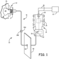
- FIG. 1 shows process control system 10 where a capillary tube 16 having connector 38B, passes through aperture 42, which is smaller than connector 38B, in accordance with an embodiment of the present invention.
- System 10 includes remote seal 12, pressure transmitter 14, capillary tube 16, vessel 18, process fluid 20, and process control circuitry 22.
- Pressure transmitter 14 includes transmitter housing 28, which contains sensor diaphragm 30, pressure sensor 32, transmitter circuitry 34 and process diaphragm 35.
- Remote seal 12 conveys the pressure of process fluid 20 to process transmitter 14, whereby sensor 32 and transmitter circuitry 34 produce a pressure reading that is conveyed to process control circuitry through control loop 36.
- Couplings 38A and 38B link remote seal 12, pressure transmitter 14 and capillary tube 16 with each other such that they can be easily, and with negligible fluid loss, connected.
- Remote seal 12 is in fluidic communication with process fluid 20 contained in vessel 18 through diaphragm 26, and with pressure transmitter 14 via capillary tube 16 and passageway 17, which are charged with a fill fluid.
- the fill fluid is a substantially incompressible hydraulic fluid for transmitting fluid pressure applied by process fluid 20 to diaphragm 26 to pressure transmitter 14.
- the hydraulic fluid comprises silicone oil, glycerin and water, propylene glycol and water, or any other fluid that is substantially incompressible, and may contain other additives.
- pressure transmitter 14 senses fluid pressure applied to diaphragm 26 by process fluid 20 through the hydraulic fill fluid.
- Process fluid 20 could, for example, be a corrosive or an extremely hot process fluid, such that pressure transmitter 14 is unable to contact, or operate in close proximity to, process fluid 20.
- remote seal 12 and capillary tube 16 are used to extend the reach of pressure transmitter 14.
- Remote seal 12 is typically bolted to vessel 18 using a flange.
- a change in the pressure of process fluid 20 is hydraulically communicated to process diaphragm 35 by the fill fluid of capillary 16. This pressure is then communicated to pressure sensor 32 with a second fill fluid positioned between process diaphragm 35 and sensor diaphragm 30.
- the deflection of sensor diaphragm 30 in response to a change in the pressure of process fluid 20 is used to determine the pressure of process fluid 20 in vessel 18 using sensor 32.
- Sensor 32 can be, for example, a capacitance-based pressure sensor, in which the capacitance of pressure sensor 32 changes as a function of the pressure of process fluid 20, or sensor 32 can operate on other known sensing principles, such as piezoresistive strain gauge technology.
- Pressure sensor 32 produces a pressure signal based on the deflection of sensor diaphragm 30 that is indicative of the pressure of process fluid 20.
- Transmitter circuitry 34 within transmitter housing 28 produces an output signal that is a function of the pressure sensed by sensor 32 and communicates the pressure signal to process control circuitry 22 over control loop 36 so that the sensed pressure of process fluid 20 can be remotely monitored.
- Process control loop 36 can be a 4-20 mA control loop, a wired digital communication network, a wireless network such as a WirelessHART network in accordance with IEC 62591, or any other suitable communication system.
- process transmitter 14 may include a local pressure indicator, such as an LCD display.
- system 10 is able to accommodate a process barrier or containment structure, illustrated diagrammatically at reference numeral 40, that allows a penetration 42 therethrough having a maximum diameter that is smaller than the diameter of remote seal 12, but larger than at least one of couplings 38A, and 38B.
- a capillary system is provided having a plurality of segments, where each segment is factory-filled. However, the segments can be joined together in the field prior to service.
- each segment is sealed with a diaphragm that is punctured at the moment when the connection between couplings 38A and 38B is formed thereby bringing two factory-filled systems together in one new closed system. After the connection is made, the fill fluid from each segment becomes part of the same closed system. Accordingly, it is preferred that the two segments contained identical fill fluid.
- Embodiments of the present invention generally provide a high quality, repeatable connection while avoiding potential issues.
- potential issues can typically occur at the moment the connection is made. Such issues include loss of fill fluid from the capillary or the introduction of air into the filled system which could later cause performance and/or reliability concerns.
- the connection needs to maintain a high quality seal. For example, for nuclear applications, such couplings must endure severe conditions comprised of radiation testing, submergence testing, saturation steam conditions, and vibration events.
- FIG. 2 is a diagrammatic view of a capillary coupling system in accordance with an embodiment of the present invention.
- System 50 includes connectors 38A and 38B, where each connector 38A and 38B is coupled to a capillary conduit 16.
- each of connectors 38A, 38B is also coupled to a respective process element, such as a remote seal or process pressure transmitter.
- the respective connector, capillary conduit 16, and process element are filled with a substantially incompressible fill fluid during manufacture, and sealed such that no air is present in the system.
- Connectors 38A and 38B are joined together in the field when the process elements are installed at the process. As illustrated in the embodiment of FIG.
- connector 38B generally has a smaller diameter than connector 38A, and thus connector 38B is generally selected to pass through process barriers or containment walls.
- connector 38B has external threads 52 that are sized and configured to engage internal threads 54 of connector 38A.
- connector 38B includes a surface 56 that includes one or more wrench flats that are configured to receive a wrench in order to impart sufficient torque to connector 38B to seal the connectors together.
- FIG. 3 is a diagrammatic cross section view of system 50 in accordance with an embodiment of the present invention.
- Each of connectors 38A and 38B includes a diaphragm 60, 62, respectively, that is configured to be pierced, or otherwise punctured when the two connectors are joined together.
- Each of diaphragms 60, 62 is preferably welded to its respective connector, at welds 64, 66, respectively. Utilization of a welded diaphragm provides a high quality, robust seal that, once punctured, will not form again. This allows for the manufacture of a closed fluid system segment. Moreover, the manufactured closed system can be controlled such that no air or other undesirable gases exist in the fluid.
- Each of diaphragms 60, 62 is preferably constructed from a 0.001 inch thick metal, such as stainless steel.
- at least one of connectors 38A and 38B includes a structure 68 that is configured to puncture the diaphragms as the two connectors are brought together.
- structure 68 is in the form of a sharp point that is spaced slightly away from diaphragm 62.
- Each connector thus forms a closed fluid system with its respective system process component, such as remote seal 12 or field device 14.
- connector 38A forms a closed fluid system segment with fill fluid extending from location 70 proximate diaphragm 62 through capillary conduit 16 to remote seal 12.
- fill fluid is also present proximate diaphragm 62 extending through capillary conduit 16 to pressure transmitter 14.
- At least one of connectors 38A and 38B preferably includes features to inhibit or otherwise prevent the introduction of air or other gases while the two connectors are joined together.
- radial elastomeric O-ring 72 is disposed within a groove 74 in surface 76.
- connector 38B also includes an O-ring configured to support a permanent seal, such as metallic O-ring 78, disposed about surface 76. When the two connectors are fully joined together, metallic O-ring 78 bears against surface 80 of connector 38A.
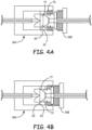
- connectors 38A and 38B will now be described with respect to FIGS. 4A-4D which show various stages of the connectors being joined together.
- FIG. 4A is a diagrammatic cross sectional view illustrating connectors 38A and 38B beginning to be joined together. Specifically, surface 76 slides within internal surface 77, and diaphragm 62 has not yet made contact with diaphragm 60.
- FIG. 4B is a diagrammatic cross sectional view of connectors 38A and 38B engaged further, in accordance with the an embodiment of the present invention.
- connector 38B has been inserted to such an extent that diaphragm 62 now bears directly against diaphragm 60.
- O-ring 72 has now made contact with internal surface 77 of connector 38A.
- FIG. 4C is a diagrammatic cross sectional view of connectors 38A and 38B further engaged in accordance with an embodiment of the present invention.
- connector 38B has been engaged to such an extent that the external threads 52 are now beginning to be engaged with internal threads 54.
- diaphragms 62, 64 have been punctured, or otherwise pierced, by piercing structure 68. Although the diaphragm has been punctured, any fill fluid leakage is minimized since O-ring 72 is now fully engaged with surface 78 thereby forming a fluid-tight seal.
- FIG. 4D is a diagrammatic cross sectional view of connectors 38A and 38B engaged further, in accordance with an embodiment of the present invention. Specifically, connector 38B is now engaged with connector 38A to such an extent that metallic O-ring 78 contacts surface 80. When finally assembled, metallic O-ring 78 is compressed between connector 38B and surface 80 of connector 38A thereby forming a permanent fluid-tight seal. Once the two connectors are joined together, as illustrated through FIGS. 4A-4D , a single closed-system is created where very little, if any, air or undesirable gases has entered the system.
- Embodiments of the present invention generally provide features where each process segment can be sealed with diaphragms that are punctured at the moment when a connection is formed between the two segments, thereby bringing the two filled systems together in one new closed system. After the connection is made, the fill fluid from each segment becomes part of the same closed system.
- Embodiments of the present invention generally reduce the chances that issues will occur during the connection process. Specifically, issues that are addressed by embodiments of the present invention include the loss of fill fluid from the capillary or the inclusion of air or other undesirable gases into the fill system which could later cause performance and reliability concerns.
- embodiments of the present invention maintain a high quality seal, which, for nuclear applications, is able to endure severe conditions comprising radiation testing, submergence testing, saturated steam conditions, and vibration events. Additionally, since O-ring 72 engages before the diaphragms are severed, oil loss can be prevented and any changes to the remote seal's oil fill constant value can be minimized to an insignificant value.
- oil fill constant is intended to mean the position of the remote seal diaphragm which indicates the volume of oil fill within the remote seal system. If the coupling mechanism described herein functions effectively, there will be negligible changes in this value, or oil volume, within the remote seal system.
- radial O-ring 72 allows the system to be sealed while allowing the assembly to slide together to puncture the diaphragms at the same time.
- the diaphragms are preferably severed by sharp mating features, which are machined into at least one and preferably each segment. When the diaphragms are pierced, the two filled systems are brought together.
- Diaphragm piercing structure 68 is generally configured to cut through the diaphragm in a consistently high-quality manner. The magnitude of force required to puncture the diaphragms may depend on diaphragm thickness, diaphragm diameter, the geometry of the leading edges, as well as the location of the initial puncture. It is believed that a design containing thin diaphragms will ensure that the diaphragms are punctured. The allowed movement of fill fluid within the capillary assembly may also facilitate the process.
- Embodiments of the present invention are generally able to repeatedly puncture diaphragms without causing pieces of the diaphragms to be fractured and enter the fill fluid system.
- the puncture, or cut made in the diaphragm must also be made in such a way that any resulting restrictions within the capillary system are negligible, and in such a way that the time response of the final capillary system is not affected by the coupling connection. Further, the diaphragms must therefore be cut in a manner in which they do not interfere with the fill fluid's flow within the capillary system.
Claims (11)
- Fernprozessdichtungsanordnung, die aufweist:eine Ferndichtung (12), die konfiguriert ist, mit einem Prozess zu koppeln, wobei die Ferndichtung (12) eine Ferndichtungsmembran (26) aufweist, die eine erste Seite, die eingerichtet ist, mit einem Prozessfluid (20) in Kontakt zu kommen, und eine zweite Seite aufweist, die eingerichtet ist, mit einem im Wesentlichen nicht komprimierbaren Füllfluid in Kontakt zu kommen;eine Kapillarleitung (16), die mit der Ferndichtung (12) gekoppelt ist, wobei die Kapillarleitung (16) mit dem im Wesentlichen nicht komprimierbaren Füllfluid gefüllt ist; dadurch gekennzeichnet, dass sie ferner aufweist:eine Kopplung (38A), die mit der Kapillarleitung (16) gekoppelt ist, wobei die Kopplung (38A) eine Dichtung aufweist, die aufbrechbar ist, wenn die Kopplung mit einer kooperativen Kopplung (38B) zusammengefügt wird, wobei die Dichtung der Kopplung (38A) und der kooperativen Kopplung (38B) jeweils eine Kopplungsmembran (60, 62) aufweisen, undwobei die Kopplung (38A) ferner eine Membran-Durchstoßstruktur (68) aufweist, die die Kopplungsmembranen (60, 62) durchstößt, wenn die Kopplung (38A) mit der kooperativen Kopplung (38A) zusammengefügt wird.
- Ferndichtungsanordnung nach Anspruch 1, wobei die Kopplungsmembranen (60, 62) mit der Kopplung bzw. der kooperativen Kopplung (38A, 38B) verschweißt sind.
- Ferndichtungsanordnung nach Anspruch 1 oder 2, wobei die Membran-Durchstoßstruktur (68) eine scharfe Spitze in der Nähe der Kopplungsmembran (60, 62) aufweist.
- Ferndichtungsanordnung nach Anspruch 3, wobei die scharfe Spitze in der Nähe einer Mitte der Kopplungsmembran (60, 62) angeordnet ist.
- Ferndichtungsanordnung nach Anspruch 1, wobei die Dichtung der Kopplung und/oder der kooperativen Kopplung (38 A, 38B) eine Werksdichtung ist.
- Prozessdruckmesssystem, das aufweist:eine Ferndichtungsanordnung, die konfiguriert ist, mit einem Prozess zu koppeln, wobei die Ferndichtungsanordnung eine Ferndichtung (12) mit einer Ferndichtungsmembran (26) aufweist, die eine erste Seite, die eingerichtet ist, mit einem Prozessfluid (20) in Kontakt zu kommen, und eine zweite Seite aufweist, die eingerichtet ist, mit einem im Wesentlichen nicht komprimierbaren Füllfluid in Kontakt zu kommen;eine erste Kapillarleitung (16), die mit der Ferndichtung (12) gekoppelt ist, wobei die erste Kapillarleitung (16) mit dem im Wesentlichen nicht komprimierbaren Füllfluid gefüllt ist;eine erste Kopplung (38A), die mit der ersten Kapillarleitung (16) gekoppelt ist;einen Prozessfluiddrucktransmitter (14) mit einem Drucksensor, der betriebsfähig mit einem Druckeinlass gekoppelt ist, dadurch gekennzeichnet, dass es ferner aufweist:eine zweite Kapillarleitung (16), die mit dem Prozessfluiddrucktransmitter (14) gekoppelt ist, wobei die zweite Kapillarleitung (16) mit dem im Wesentlichen nicht komprimierbaren Füllfluid gefüllt ist;eine zweite Kopplung (38B), die mit der zweiten Kapillarleitung (16) und mit der ersten Kopplung (38A) gekoppelt ist, um eine Fluidverbindung von der Ferndichtungsmembran (26) zum Druckeinlass des Prozessfluiddrucktransmitters (14) herzustellen; wobei die erste Kopplung (38A) und die zweite Kopplung (38B) jeweils eine Kopplungsmembran (60, 62) aufweisen;wobei die erste Kopplung (38A) eine Membran-Durchstoßstruktur (68) aufweist, die die Kopplungsmembranen (60, 62) durchstößt, wenn die erste Kopplung (38A) mit der zweiten Kopplung (38B) gekoppelt ist, undwobei mindestens eine der ersten und zweiten Kopplung (38A, 38B) so bemessen ist, dass sie durch einen Durchbruch (42) in einer Prozesseinschlussbarriere (40) hindurchgeht.
- Prozessdruckmesssystem nach Anspruch 6, wobei eine andere der ersten und zweiten Kopplung (38A, 38B) so bemessen ist, dass sie nicht durch den Durchbruch (42) hindurchgehen kann.
- Prozessflüssigkeitsdruckmesssystem nach Anspruch 6, das ferner einen metallischen O-Ring (78) aufweist, der zwischen der ersten und der zweiten Kopplung (38A, 38B) angeordnet ist.
- Prozessfluiddruckmesssystem nach Anspruch 6, das ferner einen Elastomer-O-Ring (72) aufweist, der konfiguriert ist, eine zylindrische Außenfläche der zweiten Kopplung (38B) und eine zylindrische Innenfläche der ersten Kopplung (38A) abzudichten.
- Prozessfluiddruckmesssystem nach Anspruch 6, wobei die Membran-Durchstoßstruktur (68) eine scharfe Spitze in der Nähe der Kopplungsmembran (60, 62) aufweist.
- Prozessfluiddruckmesssystem nach Anspruch 10, wobei die scharfe Spitze in der Nähe einer Mitte der Kopplungsmembran (60, 62) angeordnet ist.
Applications Claiming Priority (2)
| Application Number | Priority Date | Filing Date | Title |
|---|---|---|---|
| US13/483,686 US8720277B2 (en) | 2012-05-30 | 2012-05-30 | Process fluid pressure measurement system with improved coupling |
| PCT/US2013/037967 WO2013180853A1 (en) | 2012-05-30 | 2013-04-24 | Process fluid pressure measurement system with improved coupling |
Publications (2)
| Publication Number | Publication Date |
|---|---|
| EP2855995A1 EP2855995A1 (de) | 2015-04-08 |
| EP2855995B1 true EP2855995B1 (de) | 2023-11-15 |
Family
ID=48407808
Family Applications (1)
| Application Number | Title | Priority Date | Filing Date |
|---|---|---|---|
| EP13721859.0A Active EP2855995B1 (de) | 2012-05-30 | 2013-04-24 | Prozessflüssigkeitsdruckmesssystem mit verbesserter kopplung |
Country Status (5)
| Country | Link |
|---|---|
| US (1) | US8720277B2 (de) |
| EP (1) | EP2855995B1 (de) |
| CN (2) | CN103454031B (de) |
| IN (1) | IN2014MN01865A (de) |
| WO (1) | WO2013180853A1 (de) |
Families Citing this family (12)
| Publication number | Priority date | Publication date | Assignee | Title |
|---|---|---|---|---|
| US8720277B2 (en) * | 2012-05-30 | 2014-05-13 | Rosemount Inc. | Process fluid pressure measurement system with improved coupling |
| US9274018B2 (en) | 2012-09-28 | 2016-03-01 | Rosemount Inc. | Remote seal process pressure measuring system |
| CN105203252A (zh) | 2014-06-30 | 2015-12-30 | 罗斯蒙特公司 | 具有带类金刚石碳涂层的密封件的过程压力变送器 |
| US9899108B2 (en) * | 2015-03-30 | 2018-02-20 | Rosemount Inc. | Capillary connection through wall penetration |
| US10386001B2 (en) | 2015-03-30 | 2019-08-20 | Rosemount Inc. | Multiple field device flange |
| US9562819B2 (en) * | 2015-06-30 | 2017-02-07 | Rosemount Inc | Polymeric remote seal system for single-use containers |
| US10520383B2 (en) * | 2016-09-30 | 2019-12-31 | Rosemount Inc. | Temperature-compensating absolute pressure sensor |
| CN106653118B (zh) * | 2016-12-07 | 2018-03-06 | 中国核工业第五建设有限公司 | 充压测试系统及方法 |
| US10836990B2 (en) * | 2016-12-23 | 2020-11-17 | Cyberoptics Corporation | Sensor interface for single-use containers |
| CN110501033A (zh) * | 2018-05-17 | 2019-11-26 | 艾默生(北京)仪表有限公司 | 测量元件及包括此种测量元件的测量装置 |
| US11371899B2 (en) | 2018-05-17 | 2022-06-28 | Rosemount Inc. | Measuring element with an extended permeation resistant layer |
| DE202018005860U1 (de) * | 2018-12-17 | 2020-03-19 | Tge Marine Gas Engineering Gmbh | Überwachungsvorrichtung |
Citations (4)
| Publication number | Priority date | Publication date | Assignee | Title |
|---|---|---|---|---|
| GB1132443A (en) * | 1964-11-17 | 1968-10-30 | Cibie Projecteurs | A connecting device for hydraulic circuits |
| DE1300635B (de) * | 1964-09-07 | 1969-08-07 | Dr Med Karl Friedrich | Sterile Leitungsverbindung fuer den Durchfluss von Transfusions- oder Infusionsfluessigkeiten |
| US4089341A (en) * | 1975-01-08 | 1978-05-16 | G. Kendall Parmelee | Connector method and apparatus for coupling two systems together while excluding the environment from the system interiors |
| US5083433A (en) * | 1987-06-04 | 1992-01-28 | Automotive Products Plc | Prefilled hydraulic actuator apparatus with separate reservoir and quick-connect between them |
Family Cites Families (10)
| Publication number | Priority date | Publication date | Assignee | Title |
|---|---|---|---|---|
| US4722228A (en) * | 1985-11-20 | 1988-02-02 | Honeywell Inc. | Remote seal-type pressure signal generator |
| GB2299841B (en) | 1992-10-02 | 1997-05-14 | Pall Corp | Fluid flow conncetor assembly |
| US5811690A (en) * | 1997-03-20 | 1998-09-22 | Hershey; George E. | Differential pressure transmitter with highly accurate temperature compensation |
| US20050082828A1 (en) | 2003-09-12 | 2005-04-21 | Wicks Jeffrey C. | Releasable connection assembly for joining tubing sections |
| US7290452B2 (en) * | 2003-12-16 | 2007-11-06 | Rosemount Inc. | Remote process seal with improved stability in demanding applications |
| US7377174B2 (en) | 2004-03-18 | 2008-05-27 | Rosemount Inc. | Capillary weld extension with thermal isolation |
| US7412893B2 (en) * | 2006-03-23 | 2008-08-19 | Rosemount Inc. | Redundant mechanical and electronic remote seal system |
| US7258017B1 (en) | 2006-04-10 | 2007-08-21 | Rosemount Inc. | Industrial process pressure transmitter with field repairable remote seals |
| US7434469B2 (en) * | 2006-05-26 | 2008-10-14 | Rosemount Inc. | Remote seal installation improvements |
| US8720277B2 (en) * | 2012-05-30 | 2014-05-13 | Rosemount Inc. | Process fluid pressure measurement system with improved coupling |
-
2012
- 2012-05-30 US US13/483,686 patent/US8720277B2/en active Active
- 2012-07-27 CN CN201210265211.9A patent/CN103454031B/zh active Active
- 2012-07-27 CN CN201220370310.9U patent/CN202956245U/zh not_active Expired - Fee Related
-
2013
- 2013-04-24 EP EP13721859.0A patent/EP2855995B1/de active Active
- 2013-04-24 WO PCT/US2013/037967 patent/WO2013180853A1/en unknown
- 2013-04-24 IN IN1865MUN2014 patent/IN2014MN01865A/en unknown
Patent Citations (4)
| Publication number | Priority date | Publication date | Assignee | Title |
|---|---|---|---|---|
| DE1300635B (de) * | 1964-09-07 | 1969-08-07 | Dr Med Karl Friedrich | Sterile Leitungsverbindung fuer den Durchfluss von Transfusions- oder Infusionsfluessigkeiten |
| GB1132443A (en) * | 1964-11-17 | 1968-10-30 | Cibie Projecteurs | A connecting device for hydraulic circuits |
| US4089341A (en) * | 1975-01-08 | 1978-05-16 | G. Kendall Parmelee | Connector method and apparatus for coupling two systems together while excluding the environment from the system interiors |
| US5083433A (en) * | 1987-06-04 | 1992-01-28 | Automotive Products Plc | Prefilled hydraulic actuator apparatus with separate reservoir and quick-connect between them |
Also Published As
| Publication number | Publication date |
|---|---|
| CN103454031B (zh) | 2016-07-13 |
| IN2014MN01865A (de) | 2015-07-03 |
| WO2013180853A1 (en) | 2013-12-05 |
| CN202956245U (zh) | 2013-05-29 |
| US20130320662A1 (en) | 2013-12-05 |
| CN103454031A (zh) | 2013-12-18 |
| US8720277B2 (en) | 2014-05-13 |
| EP2855995A1 (de) | 2015-04-08 |
Similar Documents
| Publication | Publication Date | Title |
|---|---|---|
| EP2855995B1 (de) | Prozessflüssigkeitsdruckmesssystem mit verbesserter kopplung | |
| JP5819971B2 (ja) | 高静圧隔離ダイアフラム結合装置を備える工業プロセストランスミッタ | |
| JP6006426B2 (ja) | 充填管を備える圧力送信器 | |
| AU2014328656B2 (en) | Pressure sensor with mineral insulated cable | |
| RU2664762C2 (ru) | Узел технологической изолирующей мембраны для металлического технологического уплотнения | |
| EP3489649B1 (de) | System zur entfernten dichtungsdruckmessung und verwendung unter wasser | |
| EP3598097B1 (de) | Drucküberträger mit einer isolationsanordnung mit einem zweiteiligen isolatorstecker | |
| EP3049784B1 (de) | Prozessflüssigkeitsdruckmessanordnung für drucktransmitter unter hohem betriebsdruck | |
| EP2242596B1 (de) | Selbstcrimpende füllrohranordnung | |
| EP3014235B1 (de) | Prozessflüssigkeitdrucksonde mit verbessertem widerstandsvermögen | |
| US6539808B2 (en) | Press-fit remote diaphragm assembly | |
| CN106197823B (zh) | 针对高压应用的管道内过程流体压力变送器 |
Legal Events
| Date | Code | Title | Description |
|---|---|---|---|
| PUAI | Public reference made under article 153(3) epc to a published international application that has entered the european phase |
Free format text: ORIGINAL CODE: 0009012 |
|
| 17P | Request for examination filed |
Effective date: 20141016 |
|
| AK | Designated contracting states |
Kind code of ref document: A1 Designated state(s): AL AT BE BG CH CY CZ DE DK EE ES FI FR GB GR HR HU IE IS IT LI LT LU LV MC MK MT NL NO PL PT RO RS SE SI SK SM TR |
|
| AX | Request for extension of the european patent |
Extension state: BA ME |
|
| DAX | Request for extension of the european patent (deleted) | ||
| STAA | Information on the status of an ep patent application or granted ep patent |
Free format text: STATUS: EXAMINATION IS IN PROGRESS |
|
| 17Q | First examination report despatched |
Effective date: 20170404 |
|
| RAP1 | Party data changed (applicant data changed or rights of an application transferred) |
Owner name: ROSEMOUNT INC. |
|
| STAA | Information on the status of an ep patent application or granted ep patent |
Free format text: STATUS: EXAMINATION IS IN PROGRESS |
|
| STAA | Information on the status of an ep patent application or granted ep patent |
Free format text: STATUS: EXAMINATION IS IN PROGRESS |
|
| GRAP | Despatch of communication of intention to grant a patent |
Free format text: ORIGINAL CODE: EPIDOSNIGR1 |
|
| STAA | Information on the status of an ep patent application or granted ep patent |
Free format text: STATUS: GRANT OF PATENT IS INTENDED |
|
| INTG | Intention to grant announced |
Effective date: 20230623 |
|
| GRAS | Grant fee paid |
Free format text: ORIGINAL CODE: EPIDOSNIGR3 |
|
| GRAA | (expected) grant |
Free format text: ORIGINAL CODE: 0009210 |
|
| STAA | Information on the status of an ep patent application or granted ep patent |
Free format text: STATUS: THE PATENT HAS BEEN GRANTED |
|
| AK | Designated contracting states |
Kind code of ref document: B1 Designated state(s): AL AT BE BG CH CY CZ DE DK EE ES FI FR GB GR HR HU IE IS IT LI LT LU LV MC MK MT NL NO PL PT RO RS SE SI SK SM TR |
|
| REG | Reference to a national code |
Ref country code: CH Ref legal event code: EP Ref country code: GB Ref legal event code: FG4D |
|
| REG | Reference to a national code |
Ref country code: DE Ref legal event code: R096 Ref document number: 602013084929 Country of ref document: DE |
|
| REG | Reference to a national code |
Ref country code: IE Ref legal event code: FG4D |
|
| REG | Reference to a national code |
Ref country code: LT Ref legal event code: MG9D |
|
| REG | Reference to a national code |
Ref country code: NL Ref legal event code: MP Effective date: 20231115 |
|
| PG25 | Lapsed in a contracting state [announced via postgrant information from national office to epo] |
Ref country code: GR Free format text: LAPSE BECAUSE OF FAILURE TO SUBMIT A TRANSLATION OF THE DESCRIPTION OR TO PAY THE FEE WITHIN THE PRESCRIBED TIME-LIMIT Effective date: 20240216 |
|
| PG25 | Lapsed in a contracting state [announced via postgrant information from national office to epo] |
Ref country code: IS Free format text: LAPSE BECAUSE OF FAILURE TO SUBMIT A TRANSLATION OF THE DESCRIPTION OR TO PAY THE FEE WITHIN THE PRESCRIBED TIME-LIMIT Effective date: 20240315 |
|
| PG25 | Lapsed in a contracting state [announced via postgrant information from national office to epo] |
Ref country code: LT Free format text: LAPSE BECAUSE OF FAILURE TO SUBMIT A TRANSLATION OF THE DESCRIPTION OR TO PAY THE FEE WITHIN THE PRESCRIBED TIME-LIMIT Effective date: 20231115 |
|
| REG | Reference to a national code |
Ref country code: AT Ref legal event code: MK05 Ref document number: 1632070 Country of ref document: AT Kind code of ref document: T Effective date: 20231115 |
|
| PG25 | Lapsed in a contracting state [announced via postgrant information from national office to epo] |
Ref country code: NL Free format text: LAPSE BECAUSE OF FAILURE TO SUBMIT A TRANSLATION OF THE DESCRIPTION OR TO PAY THE FEE WITHIN THE PRESCRIBED TIME-LIMIT Effective date: 20231115 |
|
| PG25 | Lapsed in a contracting state [announced via postgrant information from national office to epo] |
Ref country code: AT Free format text: LAPSE BECAUSE OF FAILURE TO SUBMIT A TRANSLATION OF THE DESCRIPTION OR TO PAY THE FEE WITHIN THE PRESCRIBED TIME-LIMIT Effective date: 20231115 |
|
| PG25 | Lapsed in a contracting state [announced via postgrant information from national office to epo] |
Ref country code: ES Free format text: LAPSE BECAUSE OF FAILURE TO SUBMIT A TRANSLATION OF THE DESCRIPTION OR TO PAY THE FEE WITHIN THE PRESCRIBED TIME-LIMIT Effective date: 20231115 |
|
| PG25 | Lapsed in a contracting state [announced via postgrant information from national office to epo] |
Ref country code: NL Free format text: LAPSE BECAUSE OF FAILURE TO SUBMIT A TRANSLATION OF THE DESCRIPTION OR TO PAY THE FEE WITHIN THE PRESCRIBED TIME-LIMIT Effective date: 20231115 Ref country code: LT Free format text: LAPSE BECAUSE OF FAILURE TO SUBMIT A TRANSLATION OF THE DESCRIPTION OR TO PAY THE FEE WITHIN THE PRESCRIBED TIME-LIMIT Effective date: 20231115 Ref country code: IS Free format text: LAPSE BECAUSE OF FAILURE TO SUBMIT A TRANSLATION OF THE DESCRIPTION OR TO PAY THE FEE WITHIN THE PRESCRIBED TIME-LIMIT Effective date: 20240315 Ref country code: GR Free format text: LAPSE BECAUSE OF FAILURE TO SUBMIT A TRANSLATION OF THE DESCRIPTION OR TO PAY THE FEE WITHIN THE PRESCRIBED TIME-LIMIT Effective date: 20240216 Ref country code: ES Free format text: LAPSE BECAUSE OF FAILURE TO SUBMIT A TRANSLATION OF THE DESCRIPTION OR TO PAY THE FEE WITHIN THE PRESCRIBED TIME-LIMIT Effective date: 20231115 Ref country code: BG Free format text: LAPSE BECAUSE OF FAILURE TO SUBMIT A TRANSLATION OF THE DESCRIPTION OR TO PAY THE FEE WITHIN THE PRESCRIBED TIME-LIMIT Effective date: 20240215 Ref country code: AT Free format text: LAPSE BECAUSE OF FAILURE TO SUBMIT A TRANSLATION OF THE DESCRIPTION OR TO PAY THE FEE WITHIN THE PRESCRIBED TIME-LIMIT Effective date: 20231115 Ref country code: PT Free format text: LAPSE BECAUSE OF FAILURE TO SUBMIT A TRANSLATION OF THE DESCRIPTION OR TO PAY THE FEE WITHIN THE PRESCRIBED TIME-LIMIT Effective date: 20240315 |