EP2854586B1 - Sole structure with integrated cleat member and methods of making - Google Patents
Sole structure with integrated cleat member and methods of making Download PDFInfo
- Publication number
- EP2854586B1 EP2854586B1 EP13736682.9A EP13736682A EP2854586B1 EP 2854586 B1 EP2854586 B1 EP 2854586B1 EP 13736682 A EP13736682 A EP 13736682A EP 2854586 B1 EP2854586 B1 EP 2854586B1
- Authority
- EP
- European Patent Office
- Prior art keywords
- cleat
- protruding portion
- cases
- molding
- portions
- Prior art date
- Legal status (The legal status is an assumption and is not a legal conclusion. Google has not performed a legal analysis and makes no representation as to the accuracy of the status listed.)
- Active
Links
Images


Classifications
-
- A—HUMAN NECESSITIES
- A43—FOOTWEAR
- A43B—CHARACTERISTIC FEATURES OF FOOTWEAR; PARTS OF FOOTWEAR
- A43B13/00—Soles; Sole-and-heel integral units
- A43B13/02—Soles; Sole-and-heel integral units characterised by the material
- A43B13/026—Composites, e.g. carbon fibre or aramid fibre; the sole, one or more sole layers or sole part being made of a composite
-
- A—HUMAN NECESSITIES
- A43—FOOTWEAR
- A43B—CHARACTERISTIC FEATURES OF FOOTWEAR; PARTS OF FOOTWEAR
- A43B13/00—Soles; Sole-and-heel integral units
- A43B13/02—Soles; Sole-and-heel integral units characterised by the material
- A43B13/04—Plastics, rubber or vulcanised fibre
-
- A—HUMAN NECESSITIES
- A43—FOOTWEAR
- A43B—CHARACTERISTIC FEATURES OF FOOTWEAR; PARTS OF FOOTWEAR
- A43B13/00—Soles; Sole-and-heel integral units
- A43B13/02—Soles; Sole-and-heel integral units characterised by the material
- A43B13/12—Soles with several layers of different materials
-
- A—HUMAN NECESSITIES
- A43—FOOTWEAR
- A43B—CHARACTERISTIC FEATURES OF FOOTWEAR; PARTS OF FOOTWEAR
- A43B13/00—Soles; Sole-and-heel integral units
- A43B13/02—Soles; Sole-and-heel integral units characterised by the material
- A43B13/12—Soles with several layers of different materials
- A43B13/122—Soles with several layers of different materials characterised by the outsole or external layer
-
- A—HUMAN NECESSITIES
- A43—FOOTWEAR
- A43B—CHARACTERISTIC FEATURES OF FOOTWEAR; PARTS OF FOOTWEAR
- A43B13/00—Soles; Sole-and-heel integral units
- A43B13/14—Soles; Sole-and-heel integral units characterised by the constructive form
-
- A—HUMAN NECESSITIES
- A43—FOOTWEAR
- A43B—CHARACTERISTIC FEATURES OF FOOTWEAR; PARTS OF FOOTWEAR
- A43B13/00—Soles; Sole-and-heel integral units
- A43B13/14—Soles; Sole-and-heel integral units characterised by the constructive form
- A43B13/143—Soles; Sole-and-heel integral units characterised by the constructive form provided with wedged, concave or convex end portions, e.g. for improving roll-off of the foot
- A43B13/146—Concave end portions, e.g. with a cavity or cut-out portion
-
- A—HUMAN NECESSITIES
- A43—FOOTWEAR
- A43B—CHARACTERISTIC FEATURES OF FOOTWEAR; PARTS OF FOOTWEAR
- A43B13/00—Soles; Sole-and-heel integral units
- A43B13/14—Soles; Sole-and-heel integral units characterised by the constructive form
- A43B13/22—Soles made slip-preventing or wear-resisting, e.g. by impregnation or spreading a wear-resisting layer
- A43B13/223—Profiled soles
-
- A—HUMAN NECESSITIES
- A43—FOOTWEAR
- A43B—CHARACTERISTIC FEATURES OF FOOTWEAR; PARTS OF FOOTWEAR
- A43B13/00—Soles; Sole-and-heel integral units
- A43B13/14—Soles; Sole-and-heel integral units characterised by the constructive form
- A43B13/22—Soles made slip-preventing or wear-resisting, e.g. by impregnation or spreading a wear-resisting layer
- A43B13/24—Soles made slip-preventing or wear-resisting, e.g. by impregnation or spreading a wear-resisting layer by use of insertions
- A43B13/26—Soles made slip-preventing or wear-resisting, e.g. by impregnation or spreading a wear-resisting layer by use of insertions projecting beyond the sole surface
-
- A—HUMAN NECESSITIES
- A43—FOOTWEAR
- A43B—CHARACTERISTIC FEATURES OF FOOTWEAR; PARTS OF FOOTWEAR
- A43B13/00—Soles; Sole-and-heel integral units
- A43B13/38—Built-in insoles joined to uppers during the manufacturing process, e.g. structural insoles; Insoles glued to shoes during the manufacturing process
- A43B13/41—Built-in insoles joined to uppers during the manufacturing process, e.g. structural insoles; Insoles glued to shoes during the manufacturing process combined with heel stiffener, toe stiffener, or shank stiffener
-
- A—HUMAN NECESSITIES
- A43—FOOTWEAR
- A43B—CHARACTERISTIC FEATURES OF FOOTWEAR; PARTS OF FOOTWEAR
- A43B13/00—Soles; Sole-and-heel integral units
- A43B13/42—Filling materials located between the insole and outer sole; Stiffening materials
-
- A—HUMAN NECESSITIES
- A43—FOOTWEAR
- A43B—CHARACTERISTIC FEATURES OF FOOTWEAR; PARTS OF FOOTWEAR
- A43B5/00—Footwear for sporting purposes
- A43B5/001—Golf shoes
-
- A—HUMAN NECESSITIES
- A43—FOOTWEAR
- A43B—CHARACTERISTIC FEATURES OF FOOTWEAR; PARTS OF FOOTWEAR
- A43B5/00—Footwear for sporting purposes
- A43B5/002—Mountain boots or shoes
-
- A—HUMAN NECESSITIES
- A43—FOOTWEAR
- A43B—CHARACTERISTIC FEATURES OF FOOTWEAR; PARTS OF FOOTWEAR
- A43B5/00—Footwear for sporting purposes
- A43B5/02—Football boots or shoes, i.e. for soccer, football or rugby
-
- A—HUMAN NECESSITIES
- A43—FOOTWEAR
- A43B—CHARACTERISTIC FEATURES OF FOOTWEAR; PARTS OF FOOTWEAR
- A43B5/00—Footwear for sporting purposes
- A43B5/06—Running shoes; Track shoes
-
- A—HUMAN NECESSITIES
- A43—FOOTWEAR
- A43B—CHARACTERISTIC FEATURES OF FOOTWEAR; PARTS OF FOOTWEAR
- A43B5/00—Footwear for sporting purposes
- A43B5/14—Shoes for cyclists
-
- A—HUMAN NECESSITIES
- A43—FOOTWEAR
- A43C—FASTENINGS OR ATTACHMENTS OF FOOTWEAR; LACES IN GENERAL
- A43C15/00—Non-skid devices or attachments
- A43C15/16—Studs or cleats for football or like boots
-
- A—HUMAN NECESSITIES
- A43—FOOTWEAR
- A43C—FASTENINGS OR ATTACHMENTS OF FOOTWEAR; LACES IN GENERAL
- A43C15/00—Non-skid devices or attachments
- A43C15/16—Studs or cleats for football or like boots
- A43C15/161—Studs or cleats for football or like boots characterised by the attachment to the sole
-
- A—HUMAN NECESSITIES
- A43—FOOTWEAR
- A43C—FASTENINGS OR ATTACHMENTS OF FOOTWEAR; LACES IN GENERAL
- A43C15/00—Non-skid devices or attachments
- A43C15/16—Studs or cleats for football or like boots
- A43C15/162—Studs or cleats for football or like boots characterised by the shape
-
- B—PERFORMING OPERATIONS; TRANSPORTING
- B29—WORKING OF PLASTICS; WORKING OF SUBSTANCES IN A PLASTIC STATE IN GENERAL
- B29D—PRODUCING PARTICULAR ARTICLES FROM PLASTICS OR FROM SUBSTANCES IN A PLASTIC STATE
- B29D35/00—Producing footwear
- B29D35/0054—Producing footwear by compression moulding, vulcanising or the like; Apparatus therefor
-
- B—PERFORMING OPERATIONS; TRANSPORTING
- B29—WORKING OF PLASTICS; WORKING OF SUBSTANCES IN A PLASTIC STATE IN GENERAL
- B29D—PRODUCING PARTICULAR ARTICLES FROM PLASTICS OR FROM SUBSTANCES IN A PLASTIC STATE
- B29D35/00—Producing footwear
- B29D35/02—Producing footwear made in one piece using a moulding technique, e.g. by injection moulding or casting
- B29D35/04—Producing footwear made in one piece using a moulding technique, e.g. by injection moulding or casting having multilayered parts
-
- B—PERFORMING OPERATIONS; TRANSPORTING
- B29—WORKING OF PLASTICS; WORKING OF SUBSTANCES IN A PLASTIC STATE IN GENERAL
- B29D—PRODUCING PARTICULAR ARTICLES FROM PLASTICS OR FROM SUBSTANCES IN A PLASTIC STATE
- B29D35/00—Producing footwear
- B29D35/12—Producing parts thereof, e.g. soles, heels, uppers, by a moulding technique
- B29D35/122—Soles
-
- B—PERFORMING OPERATIONS; TRANSPORTING
- B29—WORKING OF PLASTICS; WORKING OF SUBSTANCES IN A PLASTIC STATE IN GENERAL
- B29D—PRODUCING PARTICULAR ARTICLES FROM PLASTICS OR FROM SUBSTANCES IN A PLASTIC STATE
- B29D35/00—Producing footwear
- B29D35/12—Producing parts thereof, e.g. soles, heels, uppers, by a moulding technique
- B29D35/14—Multilayered parts
- B29D35/142—Soles
-
- B—PERFORMING OPERATIONS; TRANSPORTING
- B29—WORKING OF PLASTICS; WORKING OF SUBSTANCES IN A PLASTIC STATE IN GENERAL
- B29K—INDEXING SCHEME ASSOCIATED WITH SUBCLASSES B29B, B29C OR B29D, RELATING TO MOULDING MATERIALS OR TO MATERIALS FOR MOULDS, REINFORCEMENTS, FILLERS OR PREFORMED PARTS, e.g. INSERTS
- B29K2075/00—Use of PU, i.e. polyureas or polyurethanes or derivatives thereof, as moulding material
-
- B—PERFORMING OPERATIONS; TRANSPORTING
- B29—WORKING OF PLASTICS; WORKING OF SUBSTANCES IN A PLASTIC STATE IN GENERAL
- B29K—INDEXING SCHEME ASSOCIATED WITH SUBCLASSES B29B, B29C OR B29D, RELATING TO MOULDING MATERIALS OR TO MATERIALS FOR MOULDS, REINFORCEMENTS, FILLERS OR PREFORMED PARTS, e.g. INSERTS
- B29K2105/00—Condition, form or state of moulded material or of the material to be shaped
- B29K2105/04—Condition, form or state of moulded material or of the material to be shaped cellular or porous
Definitions
- the embodiments relate generally to a sole structure with an integrated cleat member and methods of making the sole structure with the integrated cleat member.
- Document FR 1 374 227 A discloses a method for forming a shoe sole with studs, wherein the exterior sole is partially inserted in the base of the studs.
- Document FR 2 396 523 A1 discloses a sole with moulded projecting components with a curved transversal profile.
- Document US 2005/0016029 A1 discloses a soccer shoe including an upper and a cleat assembly coupled to the upper.
- the cleat assembly further includes a medial support bar located on the medial side and a lateral support bar located on the lateral side.
- a method of making a sole structure includes reshaping a portion of a plate member to form a protruding portion for a cleat member, where the protruding portion has a convex outer portion and a concave inner portion.
- the method also includes forming a first hole and a second hole in the protruding portion, where the holes provide fluid communication between the outer portion and the inner portion.
- the method also includes molding a pair of cleat portions onto the outer portion and molding a supporting structure within the inner portion. The pair of cleat tip portions is connected to the supporting structure through the holes.
- the following discussion and accompanying figures disclose a sole structure for an article of footwear.
- Concepts associated with the sole structure may be applied to a variety of athletic footwear types, including soccer shoes, running shoes, baseball shoes, basketball shoes, cross-training shoes, cycling shoes, football shoes, golf shoes, tennis shoes, walking shoes, and hiking shoes and boots, for example.
- the concepts may also be applied to footwear types that are generally considered to be non-athletic, including dress shoes, loafers, sandals, and work boots. Accordingly, the concepts disclosed herein apply to a wide variety of footwear types.
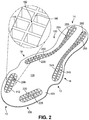
- FIGS. 1 and 2 illustrate isometric views of an embodiment of sole structure 100.
- FIG. 1 illustrates an isometric view of a bottom side of sole structure 100
- FIG. 2 illustrates an isometric view of a top side of sole structure 100.
- sole structure 100 is shown in isolation in FIGS. 1 and 2 .
- sole structure 100 could be incorporated into the sole of an article and/or associated with an upper.
- Sole structure 100 may generally comprise any portion of a sole for an article of footwear.
- sole structure 100 could comprise a portion of an insole.
- sole structure 100 could comprise a portion of a midsole.
- sole structure 100 could comprise an outsole for an article that is configured to come into contact with a ground surface. In some embodiments, sole structure 100 may form the entire outsole of an article of footwear. In other embodiments, sole structure 100 may form only a portion of an outsole of an article of footwear. Moreover, in cases where sole structure 100 comprises an outsole, sole structure 100 could be attached to any other component of a sole structure (such as a midsole or insole). In other cases, sole structure 100 could be attached directly to an upper of an article of footwear. Additionally, in other embodiments, different configurations of sole structure 100 may be included in an article of footwear.
- components of sole structure 100 may be divided into forefoot portion 10, midfoot portion 12 and heel portion 14.
- Forefoot portion 10 may be generally associated with the toes and joints connecting the metatarsals with the phalanges.
- Midfoot portion 12 may be generally associated with the arch of a foot.
- heel portion 14 may be generally associated with the heel of a foot, including the calcaneus bone.
- sole structure 100 may include lateral side 16 and medial side 18.
- lateral side 16 and medial side 18 may be opposing sides of sole structure 100.
- both lateral side 16 and medial side 18 may extend through forefoot portion 10, midfoot portion 12 and heel portion 14.
- forefoot portion 10, midfoot portion 12 and heel portion 14 are only intended for purposes of description and are not intended to demarcate precise regions of sole structure 100.
- lateral side 16 and medial side 18 are intended to represent generally two sides of a sole structure, rather than precisely demarcating sole structure 100 into two halves.
- forefoot portion 10, midfoot portion 12 and heel portion 14, as well as lateral side 16 and medial side 18, can also be applied to individual components of a sole structure, such as a sockliner, insole or any other component.
- longitudinal refers to a direction extending a length of a component. In some cases, the longitudinal direction may extend from a forefoot portion to a heel portion of the sole structure.
- lateral refers to a direction extending a width of the sole structure. In other words, the lateral direction may extend between a medial side and a lateral side of the sole structure.
- vertical refers to a direction generally perpendicular to a lateral and longitudinal direction.
- proximal refers to a portion of a footwear component that is closer to a portion of a foot when an article of footwear is worn.
- distal refers to a portion of a footwear component that is further from a portion of a foot when an article of footwear is worn. It will be understood that each of these directional adjectives may be applied to individual components of an article and/or a sole structure.
- sole structure 100 may comprise plate member 103.
- plate member 103 can be a full length plate member, including a forefoot portion, a midfoot portion and a heel portion. In other cases, however, plate member 103 may be a partial length plate member. For example, in some cases, plate member 103 may only extend through the forefoot of an article of footwear.
- sole structure 100 can include a plurality of cleat members 102 disposed on lower surface 104 of plate member 103.
- cleat member as used throughout this detailed specification and throughout the claims includes any provision disposed on a sole structure for increasing traction through friction or penetration of a ground surface.
- plurality of cleat members 102 includes first cleat member 110, second cleat member 120, third cleat member 130, fourth cleat member 140, fifth cleat member 150, and sixth cleat member 160.
- cleat members 102 could include less than six cleat members. In still other embodiments, cleat members 102 could include more than six cleat members.
- cleat members 102 could be disposed in any arrangement on plate member 103. In some cases, some of cleat members 102 could be disposed in forefoot portion 10. In other cases, some of cleat members 102 could be disposed in midfoot portion 12. In some cases, some of cleat members 102 could be disposed in heel portion 14. In one embodiment, first cleat member 110 and second cleat member 120 are disposed in forefoot portion 10. Also, in one embodiment, third cleat member 130 and fourth cleat member 140 are disposed in midfoot portion 12. Additionally, in one embodiment, fifth cleat member 150 and sixth cleat member 160 are disposed in heel portion 14. However, any other arrangement of cleat members 102 are possible. For example, the current embodiment includes cleat members that are disposed on a peripheral portion 106 of plate member 103. In other cases, however, some cleat members could be disposed more centrally on plate member 103.
- the embodiments are not limited to cleat members having a particular shape and/or geometry.
- some embodiments could incorporate cleat members having different geometries and/or shapes, which may be selected according to various factors including desired traction properties, weight properties, stability properties as well as possible other factors.
- the geometry and/or shape of one or more cleat members could vary according to the intended sport for which sole structure 100 may be used.
- the geometry and/or shape of one or more cleat members could be selected according to whether sole structure 100 is intended for use in football, soccer, baseball, golf as well as possibly other sports, as each sport may be associated with cleats having particular geometric characteristics.
- Some embodiments may include provisions for reducing the overall weight of sole structure 100 while maintaining durability of cleat members 102.
- a portion of a cleat member could be integrally formed with a plate member.
- a portion of a cleat member can comprise a protruding portion that is integral with a plate member.
- plate member 103 includes protruding portion 112 (shown in an enlarged cross-section within FIG. 1 ) that is integrally formed with plate member 103.
- Protruding portion 112 may include an outer portion 114 that extends out in a convex manner from lower surface 104 of plate member 103.
- Protruding portion 112 may also include an inner portion 116 that is recessed in a concave manner with respect to upper surface 105 of plate member 103. With this configuration, protruding portion 112 provides an integrally formed first portion 118 for first cleat member 110 that extends outwardly from lower surface 104 of plate member 103.
- first cleat member 110 further includes second portion 119.
- second portion 119 comprises first pair of cleat tip portions 170.
- First pair of cleat tip portions 170 includes first cleat tip portion 171 and second cleat tip portion 172 that are spaced apart by gap 173.
- second portion 119 could include a single cleat tip portion.
- second portion 119 could include three or more distinct cleat tip portions.
- second portion 119 can also include connecting portion 174.
- connecting portion 174 wraps around sidewalls 115 of protruding portion 112.
- Connecting portion 174 may be configured to connect first cleat tip portion 171 with second cleat tip portion 172.
- connecting portion 174 can provide a connection between pair of cleat tip portions 170 and any other portions of sole member 100.
- a sole member can include provisions for increasing the strength of a protruding portion.
- a protruding portion can be configured with a supporting structure.
- a supporting structure can be any structure configured to reinforce or otherwise enhance support for a protruding portion.
- a supporting structure can also help to anchor one or more cleat tip portions to a protruding portion.
- protruding portion 112 can be associated with first supporting structure 180.
- first supporting structure 180 may comprise a lattice like structure that is disposed within inner portion 116 of protruding portion 112.
- first supporting structure 180 comprises a plurality of intersecting ribs or walls that are arranged approximately along the longitudinal and lateral directions of protruding portion 112.
- the geometry of supporting structure 180 can vary. Any three-dimensional geometry and/or two-dimensional geometry could be used for supporting structure 180.
- supporting structure 180 has a square or rectangular lattice-like cross-sectional geometry.
- supporting structure 180 could have a hexagonal lattice-like, or honeycomb shaped, cross-sectional geometry.
- the cross-sectional geometry could be associated with any other shapes including triangles, rectangles, circles, ellipses, polygons, regular shapes as well as irregular shapes.
- the pattern associated with supporting structure 180 could be constant or could vary over different regions. It will be understood that the geometry of a supporting structure could be selected according to the desired strength characteristics for a protruding portion as well as the geometry of the protruding portion.
- supporting structure 180 could extend throughout the substantial entirety of inner portion 116. In other cases, supporting structure 180 could extend through only a part of inner portion 116. In some cases, a supporting structure 180 could have a variable height that is contoured to fit the shape of inner portion 116. In some cases, surface 182 of supporting structure 180 could be approximately flush with upper surface 105 of plate member 103.
- protruding portion 112 includes first hole 191 and second hole 192.
- supporting structure 180 and first pair of cleat tip portions 170 can be connected through first hole 191 and second hole 192.
- first pair of cleat tip portions 170 and supporting structure 180 comprise a substantially continuous material portion that are joined through first hole 191 and second hole 192. This arrangement helps to anchor pair of cleat tip portions 170 to protruding portion 112.
- each of the remaining cleat members may be configured in a similar manner to first cleat member 110.
- each of second cleat member 120, third cleat member 130, fourth cleat member 140, fifth cleat member 150 and sixth cleat member 160 include corresponding protruding portion 220, protruding portion 230, protruding portion 240, protruding portion 250 and protruding portion 260, respectively, which may be collectively referred to along with protruding portion 112 as protruding portions 280.
- Each protruding portion includes a corresponding convex outer portion along lower surface 104 and a corresponding concave inner portion along upper surface 105.
- protruding portion 240 and protruding portion 260 could be continuous with one another, forming intermediate ridge portion 210 on lower surface 104.
- protruding portion 230 and protruding portion 250 could be continuous with one another, forming intermediate ridge portion 212 on lower surface 104.
- plate member 103 may not include ridge portion 210 and/or ridge portion 212.
- each of second cleat member 120, third cleat member 130, fourth cleat member 140, fifth cleat member 150 and sixth cleat member 160 may include corresponding pair of tip portions 226, pair of tip portions 236, pair of tip portions 246, pair of tip portions 256 and pair of tip portions 266, respectively, which may be collectively referred to along with pair of tip portions 170 as plurality of cleat tip portions 286.
- some cleat members can include cleat tip portions, while others may not include cleat tip portions. In other words, in some cases, cleat tip portions may be optional.
- each of second cleat member 120, third cleat member 130, fourth cleat member 140, fifth cleat member 150 and sixth cleat member 160 may include corresponding connecting portion 228, connecting portion 238, connecting portion 248, connecting portion 258 and connecting portion 268, respectively, which may be collectively referred to along with connecting portion 174 as plurality of connecting portions 290.
- some cleat members can include connecting portions, while others may not include connecting portions. In other words, in some cases, connecting portions may be optional.
- each of cleat members 102 can also include a corresponding supporting structure.
- second cleat member 120, third cleat member 130, fourth cleat member 140, fifth cleat member 150 and sixth cleat member 160 may include corresponding supporting structure 225, supporting structure 235, supporting structure 245, supporting structure 255 and supporting structure 265, respectively, which may be referred to collectively as plurality of supporting structures 296.
- some cleat members can include supporting structures, while others may not include supporting structures. In other words, in some cases, supporting structures may be optional.
- each cleat member can be configured in a similar manner.
- each cleat member comprises a first portion that is integrally formed with a plate member and provides a base like protruding portion for the cleat.
- each cleat member comprises a second portion that is attached to the first portion, where the second portion comprises cleat tip portions that further enhance the traction provided by the cleat member.
- each cleat member is formed with a hollow inner portion that is filled with a supporting structure.
- plurality of protruding portions 280 are filled with plurality of supporting structures 296. The supporting structures help increase the structural integrity of the cleat member and can provide anchoring for cleat tip portions 286.
- plurality of cleat tip portions 286 may be integrally formed with plurality of connecting portions 290. Moreover, each of connecting portions 290 can be connected to peripheral layer 298 that extends around peripheral portion 106 of plate 103 on lower surface 104. In some cases, as discussed in further detail below, plurality of cleat tip portions 286, plurality of connecting portions 290 and peripheral layer 298 may comprise a single molded layer that is disposed over lower surface 104 of plate member 103. In other cases, however, some of these various portions may not be connected to one another.
- FIGS. 3 through 10 are intended to illustrate one embodiment of a process for making a sole structure including integrated cleat members.
- some of the steps associated with the process could be accomplished by a proprietor, a manufacturer, a retailer or any other entity. It will be understood that in some embodiments one or more of the steps associated with the process may be optional. In other embodiments, some additional steps could be included that are not discussed below. Additionally, the order of the steps discussed below could be rearranged in any desired manner.
- plate member 103 can comprise different materials with different characteristics.
- plate member 103 can comprise a composite material.
- composite material refers to any material made from two or more materials with differing material properties that retain some amount of separation within the composite material.
- plate member 103 may be made of a fiber-reinforced composite material including short fiber-reinforced materials and continuous fiber-reinforced materials. Examples of fiber-reinforced materials include, but are not limited to: wood, carbon-fiber reinforced plastics and glass reinforced plastics.
- plate member 103 comprises a carbon fiber reinforced composite.
- An exemplary composite structure is disclosed in Auger, U.S. Patent Number 7,832,117, issued November 16, 2010 , the entirety of which is hereby incorporated by reference. In other cases, however, plate member 103 could be made of any other materials, including materials with relatively high rigidities or materials with relatively low rigidities.
- cleat tip portions 286, connecting portions 290 and/or supporting structures 296 may comprise substantially similar materials. Examples of materials that could be used for these components include, but are not limited to: plastics, rubbers, metals as well as any other materials.
- each of cleat tip portions 286, connecting portions 290 and supporting structures 296 may comprise a relatively soft and/or flexible plastic material, such as thermoplastic polyurethane (TPU).
- TPU thermoplastic polyurethane
- these different portions could comprise different materials.
- cleat tip portions 286 and supporting structures 296 could be made of substantially different plastic materials.
- the arrangement described above provides an integrated cleat member with a strong base (a protruding portion) that is integrally formed with substantially rigid composite plate. This arrangement further provides a cleat member with a more flexible cleat tip that provides for adaptability of the cleat tip on different kinds of surfaces and enhances penetration into a ground surface.
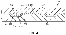
- FIGS. 3 and 4 illustrate schematic views of an embodiment of a process for forming a plurality of protruding portions on a plate member.
- plate member 103 could be associated with shaping assembly 310.
- plate member 103 could be configured with any geometry.
- plate member 103 may have any approximately two-dimensional geometry, such that the width and length are substantially greater than the depth of plate member 103.
- the depth of plate member 103 could vary such that plate member 103 is better described as three-dimensional.
- plate member 103 could have a substantially flat geometry.
- plate member 103 comprises a substantially flat layer.
- plate member 103 could have a curved or contoured geometry.
- plate member 103 could be pre-shaped with the geometry of an outsole including a contoured periphery that slopes upwardly towards a midsole component or upper of an article of footwear.
- plate member 103 may have a substantially flat geometry without any protrusions.
- the geometry of plate member 103 could be slightly contoured.
- plate member 103 could be pre-shaped to have an outer edge 302 that has the approximate shape of an outsole or other sole component.
- a rectangular sheet of stock composite material may be shaped using shaping assembly 310 and then cut to the shape of an outsole or other sole component.
- Shaping assembly 310 can be any machine or device known in the art for shaping or otherwise deforming various different kinds of materials including rigid materials.
- shaping assembly 310 comprises a press that is configured to re-shape one or more portions of a rigid material using pressure and/or heat.
- shaping assembly 310 could include a top molding portion and a bottom molding portion that are used to reshape a rigid material.
- shaping assembly 310 may use pressure to reshape portions of plate member 103.
- shaping assembly 310 may use heat to reshape portions of plate member 103.
- shaping assembly 310 may use heat and pressure to reshape portions of plate member 103.
- shaping assembly 310 could be part of a device that uses an autoclave molding technique to shape composite materials.
- shaping assembly 310 comprises top molding plate 312 and bottom molding plate 314.
- top molding plate 312 and bottom molding plate 314 provide molding surfaces that can be used to reshape on one or more portions of plate member 103.
- top molding plate 312 could be provided with protrusions 320.
- bottom molding plate 314 could be provided with recesses 322 that correspond with protrusions 320. As seen in FIGS. 3 and 4 , to form protrusions in plate member 103, protrusions 320 and recesses 322 of top molding plate 312 and bottom molding plate 314 may be aligned on opposing sides of plate member 103.
- protruding portions 280 are formed.
- first portion 330 of plate member 103 is aligned with first protruding portion 331 of top molding plate 312 and first recess 332 of bottom molding plate 314.
- first portion 330 is reshaped to form first protruding portion 112, including concave inner portion 116 and convex outer portion 114.
- each of the remaining protruding portions discussed above can be formed in a similar manner using corresponding protrusions 320 and recesses 322 of shaping assembly 310.
- the current embodiment illustrates a process for forming a plurality of protruding portions simultaneously, in other embodiments two or more different protrusions can be formed during different steps.
- protruding portions can be formed one at a time by applying a shaping assembly to a localized region of a plate member.
- a plate member or similar sole component could be molded from a liquid and/or foam molding material.
- a molding assembly can be used to form a sole component from a rubber and/or plastic material.
- FIGS. 5 and 6 illustrate isometric views of upper surface 105 and lower surface 104, respectively, of plate member 103 after being removed from shaping assembly 310.
- plate member 103 has been reshaped and includes protruding portions 280 that extend outwardly from lower surface 104.
- plate member 103 includes first protruding portion 112, second protruding portion 220, third protruding portion 230, fourth protruding portion 240, fifth protruding portion 250 and sixth protruding portion 260.
- Each protruding portion includes a corresponding inner concave portion and outer convex portion.
- first protruding portion 112 includes inner portion 114 and outer portion 116.
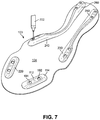
- FIG. 7 illustrates an embodiment of a possible step in the method where holes are formed in one or more protruding portions.
- two holes are formed in each protruding portion.
- first hole 191 and second hole 192 are formed in first protruding portion 112.
- first hole 191 and second hole 192 may extend through the entire thickness of first protruding portion 112. This allows fluid communication between outer portion 114 and inner portion 116, as seen in FIG. 1 .
- holes may also be formed in each of second protruding portion 220, third protruding portion 230, fourth protruding portion 240, fifth protruding portion 250 and sixth protruding portion 260.
- each protruding portion could include a single hole. In still other cases, each protruding portion could include more than two holes. Moreover, in some cases, some protruding portions could include holes, while other protruding portions may not include holes.
- each hole may have an approximately circular shape. In other cases, however, each hole could have any other shape including, but not limited to: triangular shapes, rectangular shapes, oval shapes, polygonal shapes, regular shapes and/or irregular shapes. In addition, the size of each hole could be varied in any manner.
- each hole may be formed using water jet cutter 702 that uses high pressure and high velocity water to cut through rigid materials.
- holes could be formed using any other techniques known in the art including, but not limited to laser cutting techniques, drilling and punching.
- holes could be formed simultaneously with a protruding portion. For example, in an embodiment where a portion of a plate member is reshaped to form a protruding portion, a hole could be punched from the plate member as the protruding portion is being formed using a molding plate.
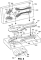
- FIGS. 8 -10 illustrate embodiments of a method of forming cleat tip portions and support structures on a plate member.
- FIG. 8 illustrates a schematic view of plate member 103 inserting into molding assembly 800
- FIGS. 9 and 10 illustrate cross sectional views of a protruding portion inside a portion of molding assembly 800.
- molding assembly 800 comprises top molding plate 802 and bottom molding plate 804.
- molding assembly 800 is shown schematically in the current embodiment, however it will be understood that molding assembly 800 can be representative of any type of molding device, machine or system known in the art.
- top molding plate 802 is configured with provisions for forming supporting structures.
- top molding plate 802 includes spacer portions 820.
- Spacer portions 820 comprise projections that extend outwardly from top molding plate 802.
- spacer portions 820 are integrally formed with top molding plate 802.
- top molding plate 802 comprises a metal material
- spacer portions 820 may comprise a substantially similar metal material.
- spacer portions 820 may not be integrally formed with top molding plate 802.
- spacer portions 820 could be removable from top molding plate 802.
- spacer portions 820 are arranged in sets that correspond with each protruding portion of plate member 103.
- first set of spacer portions 822 are configured to insert into inner portion 116 of first protruding portion 112, as shown in FIG. 9 .
- second set of spacer portions 824, third set of spacer portions 826, fourth set of spacer portions 828, fifth set of spacer portions 830 and sixth set of spacer portions 832 are configured to insert into second protruding portion 220, third protruding portion 230, fourth protruding portion 240, fifth protruding portion 250 and sixth protruding portion 260, respectively.
- first set of spacer portions 822 includes spacer portions approximately aligned in two longitudinal rows and eight lateral rows. The spacer portions are separated by gaps 831 where molding material may be filled in between the spacer portions.
- each spacer portion can be varied.
- the shape of each spacer portion can be contoured so that each set of spacer portions has an overall shape corresponding to the approximate shape of an associated protruding portion.
- the spacer portions of first set of spacer portions 822 include contoured outer edges 840 that are contoured to the shape of outer edge 850 of first protruding portion 112.
- the heights of one or more spacer portions could be constant. In other cases, the heights of one or more spacer portions could be varied to accommodate the contours of first protruding portion 112.
- the spacer portions of the majority of first set of spacer portions 822 have approximately constant heights. In this case, the outermost spacer portions 839 have shorter heights to accommodate the slope of inner portion 116, as seen in FIG. 9 .
- bottom molding plate 804 includes provisions for forming cleat tip portions on lower surface 104 of plate member 103.
- bottom molding plate 804 includes molding cavities 860.
- Molding cavities 860 comprise recesses that are sunken in from upper surface 805 of bottom molding plate 804.
- Molding cavities 860 may include first molding cavity 862, second molding cavity 864, third molding cavity 866, fourth molding cavity 868, fifth molding cavity 870 and sixth molding cavity 872, corresponding to first protruding portion 112, second protruding portion 220, third protruding portion 230, fourth protruding portion 240, fifth protruding portion 250 and sixth protruding portion 260, respectively.
- each molding cavity may be shaped to form corresponding cleat tip portions and connecting portions on a protruding portion.
- first molding cavity 862 can include recessed portion 880 that may receive sidewall portions 115 of first protruding portion 112.
- first molding cavity 862 further includes first sub-recess 882 and second sub-recess 884, which are recessed with respect to recessed portion 880.
- First sub-recess 882 and second sub-recess 884 may be shaped to form first cleat tip portion 171 and second cleat tip portion 172 of first cleat member 110, as shown in FIG. 1 .
- each of the remaining molding cavities 860 can be configured in a substantially similar manner to first molding cavity 862.
- each of second molding cavity 864, third molding cavity 866, fourth molding cavity 868, fifth molding cavity 870 and sixth molding cavity 872 can include similar recessed portions to form cleat tip portions and connecting portions on second protruding portion 220, third protruding portion 230, fourth protruding portion 240, fifth protruding portion 250 and sixth protruding portion 260, respectively.
- bottom molding plate 804 can also include peripheral cavity 890 that extends between molding cavities 860.
- Peripheral cavity 890 may be a relatively shallow cavity that is used to form peripheral layer 298 (see FIG. 1 ). In other embodiments, bottom molding plate 804 may not include peripheral cavity 890.
- first set of spacer portions 822 of top molding plate 802 are inserted into inner portion 116 of first protruding portion 112.
- first protruding portion 112 is disposed within first molding cavity 862 of bottom molding plate 804.
- injection nozzle 900 may be aligned with an injecting port 902 of top molding plate 802.
- the current embodiment illustrates an injection port 902 associated with top molding plate 802 in the region of first set of spacer portions 822.
- an injection port could be associated with any other portion of molding assembly 800, including top molding plate 802 and/or bottom molding plate 804.
- multiple injection ports can be used at multiple locations of molding assembly 800.
- each set of spacer portions of top molding plate 802 could include a separate injection port.
- each molding cavity of bottom molding plate 804 could include a separate injection port.
- molding material 1000 injected through first set of spacer portions 822. This allows the molding material to fill into gaps 831 to form first supporting structure 180. Moreover, molding material 1000 may flow through first hole 191 and second hole 192 of protruding portion 112 into molding cavity 862. Thus, molding material 1000 is able to cover sidewall portions 115 of first protruding portion 112 to form first connecting portion 174. Also, molding material 1000 may fill into first sub-recess 882 and second sub-recess 884 in order to form first cleat tip portion 171 and second cleat tip portion 172.
- molding material 1000 could comprise any material.
- molding material 1000 comprises a plastic material, such as thermoplastic polyurethane (TPU).
- TPU thermoplastic polyurethane
- molding material 1000 could be any other material.
- Molding material 1000 could be selected to achieve desired material properties for cleat tip portions and connecting portions of a cleat member.
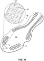
- FIG. 11 illustrates an alternative embodiment of sole structure 100 in which the gaps of supporting structure 180 have been filled with material 1102.
- material 1102 can be inserted into supporting structure 180 after support structure 180 has been formed. In other cases, however, material 1102 could be formed substantially simultaneously with support structure 180, for example using a multi-shot molding process.
- material 1102 could be any material. In some cases, material 1102 could be a foam material. In other cases, material 1102 could be a plastic material. Material 1102 may be selected in order to achieve desired characteristics for cleat member 110. For example, to increase strength and rigidity for cleat member 110, material 1102 could be a relatively rigid material. In other cases, to increase cushioning, material 1102 could be a foam or soft plastic material.
- FIG. 12 illustrates a cross sectional view of an embodiment of an optional step of a process for making a cleat member.
- a protruding portion 1312 of a plate member 1303 may be formed without any holes.
- molding assembly 800 can include a first injection nozzle 1302 and a second injection nozzle 1304 associated with top molding plate 802 and bottom molding plate 804. This allows a first material 1322 to be injected into inner portion 1316 of protruding portion 1312 and a second material 1324 to be injected over outer portion 1314 of protruding portion 1312.
- first material 1322 and second material 1324 could be substantially different materials. In some cases, for example, first material 1322 could be substantially more rigid than second material 1324. In other cases, second material 1324 could be substantially more rigid than first material 1322. In still other cases, first material 1322 and second material 1324 could be substantially similar materials. For example, in one embodiment, first material 1322 and second material 1324 could both be TPU.
- outer portion 1314 of protruding portion 1312 illustrates a single layer of material on outer portion 1314 of protruding portion 1312
- other embodiments could incorporate two or more layers.
- another embodiment may use two layers on outer portion 1314, where the outermost layer could be substantially more abrasion resistant than the layer directly adjacent to outer portion 1314.
- Cleat member 1410 includes cleat tip portions 1470 and connecting portion 1474 on outer portion 1314 of protruding portion 1312 associated with outer surface 1304 of plate member 1303.
- supporting structure 1480 is formed on an inner portion 1316 of protruding portion 1312.
- cleat tip portions 1470 are not connected to supporting structure 1480.
Landscapes
- Engineering & Computer Science (AREA)
- Chemical & Material Sciences (AREA)
- Materials Engineering (AREA)
- Mechanical Engineering (AREA)
- Health & Medical Sciences (AREA)
- General Health & Medical Sciences (AREA)
- Physical Education & Sports Medicine (AREA)
- Footwear And Its Accessory, Manufacturing Method And Apparatuses (AREA)
Priority Applications (1)
| Application Number | Priority Date | Filing Date | Title |
|---|---|---|---|
| EP17001725.5A EP3295816B1 (en) | 2012-06-04 | 2013-05-31 | Sole structure with integrated cleat member |
Applications Claiming Priority (2)
| Application Number | Priority Date | Filing Date | Title |
|---|---|---|---|
| US13/487,962 US9615621B2 (en) | 2012-06-04 | 2012-06-04 | Sole structure with integrated cleat member and methods of making |
| PCT/US2013/043550 WO2013184497A2 (en) | 2012-06-04 | 2013-05-31 | Sole structure with integrated cleat member and methods of making |
Related Child Applications (1)
| Application Number | Title | Priority Date | Filing Date |
|---|---|---|---|
| EP17001725.5A Division EP3295816B1 (en) | 2012-06-04 | 2013-05-31 | Sole structure with integrated cleat member |
Publications (2)
| Publication Number | Publication Date |
|---|---|
| EP2854586A2 EP2854586A2 (en) | 2015-04-08 |
| EP2854586B1 true EP2854586B1 (en) | 2017-11-01 |
Family
ID=48783331
Family Applications (2)
| Application Number | Title | Priority Date | Filing Date |
|---|---|---|---|
| EP13736682.9A Active EP2854586B1 (en) | 2012-06-04 | 2013-05-31 | Sole structure with integrated cleat member and methods of making |
| EP17001725.5A Active EP3295816B1 (en) | 2012-06-04 | 2013-05-31 | Sole structure with integrated cleat member |
Family Applications After (1)
| Application Number | Title | Priority Date | Filing Date |
|---|---|---|---|
| EP17001725.5A Active EP3295816B1 (en) | 2012-06-04 | 2013-05-31 | Sole structure with integrated cleat member |
Country Status (5)
| Country | Link |
|---|---|
| US (3) | US9615621B2 (enExample) |
| EP (2) | EP2854586B1 (enExample) |
| JP (2) | JP6125623B2 (enExample) |
| CN (1) | CN104540409B (enExample) |
| WO (1) | WO2013184497A2 (enExample) |
Families Citing this family (41)
| Publication number | Priority date | Publication date | Assignee | Title |
|---|---|---|---|---|
| US9545129B2 (en) * | 2011-03-08 | 2017-01-17 | Athalonz, Llc | Baseball shoe with cleat pattern for pitching |
| US10674786B2 (en) | 2011-03-08 | 2020-06-09 | Athalonz, Llc | Athletic positioning apparatus including a heel platform and applications thereof |
| US9839255B2 (en) * | 2012-06-20 | 2017-12-12 | Nike, Inc. | Sole structure for article of footwear |
| USD728210S1 (en) * | 2013-04-18 | 2015-05-05 | Kumkang Shoe Co., Ltd. | Shoe outsole |
| US10391705B2 (en) * | 2014-05-09 | 2019-08-27 | Nike, Inc. | System and method for forming three-dimensional structures |
| US9930934B2 (en) * | 2014-07-03 | 2018-04-03 | Nike, Inc. | Article of footwear with a segmented plate |
| US10016919B2 (en) * | 2014-07-03 | 2018-07-10 | Nike, Inc. | Method of making an article of footwear with a segmented plate |
| DE102014115609B4 (de) * | 2014-10-27 | 2017-01-05 | Teng-Jen Yang | Verfahren zur Herstellung einer während der Formgebung gleichzeitig mit Schuhspikes verbundenen Schuhbodenkonstruktion sowie eine entsprechende Schuhbodenkonstruktion mit Schuhspikes |
| USD735982S1 (en) * | 2014-12-23 | 2015-08-11 | Nike, Inc. | Shoe outsole |
| US9820530B2 (en) | 2015-01-16 | 2017-11-21 | Nike, Inc. | Knit article of footwear with customized midsole and customized cleat arrangement |
| US9775401B2 (en) | 2015-01-16 | 2017-10-03 | Nike, Inc. | Sole system for an article of footwear incorporating a knitted component with a one-piece knit outsole |
| US9848673B2 (en) * | 2015-01-16 | 2017-12-26 | Nike, Inc. | Vacuum formed knit sole system for an article of footwear incorporating a knitted component |
| US10568383B2 (en) | 2015-01-16 | 2020-02-25 | Nike, Inc. | Sole system for an article of footwear incorporating a knitted component with a one-piece knit outsole and a tensile element |
| US9820529B2 (en) * | 2015-02-20 | 2017-11-21 | Nike, Inc. | Asymmetric torsion plate and composite sole structure for article of footwear |
| CN112353041B (zh) * | 2015-08-25 | 2022-03-18 | 耐克创新有限合伙公司 | 具有载体和框架的鞋类鞋底结构 |
| USD802899S1 (en) * | 2015-10-30 | 2017-11-21 | Reebok International Limited | Shoe |
| US11019879B2 (en) * | 2015-11-18 | 2021-06-01 | Reebok International Limited | Extruded components for articles of footwear and methods of making the same |
| WO2017115417A1 (ja) * | 2015-12-28 | 2017-07-06 | 株式会社アシックス | 靴用部材、靴、及びその製造方法 |
| USD845597S1 (en) * | 2017-03-06 | 2019-04-16 | Adidas Ag | Shoe |
| USD798562S1 (en) * | 2017-04-21 | 2017-10-03 | Nike, Inc. | Shoe outsole |
| USD847477S1 (en) * | 2017-06-29 | 2019-05-07 | Nike, Inc. | Shoe outsole |
| USD864542S1 (en) * | 2017-12-13 | 2019-10-29 | Under Armour, Inc. | Sole structure |
| US20200147911A1 (en) * | 2018-11-14 | 2020-05-14 | Dean Shoes Company Ltd | Manufacturing method of injection molded composite shoe sole and sole thereof |
| JP7217689B2 (ja) * | 2018-12-20 | 2023-02-03 | アクシュネット カンパニー | 全表面型トラクション領域を伴うアウトソールを具備するゴルフ靴 |
| JP2020141737A (ja) * | 2019-03-04 | 2020-09-10 | 美津濃株式会社 | アウトソール構造、その製造方法、およびアウトソール構造を用いたクリーツシューズ |
| JP6903088B2 (ja) * | 2019-03-27 | 2021-07-14 | 美津濃株式会社 | ソール構造用部材の製造方法 |
| US11944158B2 (en) * | 2019-09-03 | 2024-04-02 | Adidas Ag | Sole element |
| USD966678S1 (en) * | 2019-10-11 | 2022-10-18 | Adidas Ag | Shoe |
| USD937550S1 (en) * | 2020-07-24 | 2021-12-07 | Nike, Inc. | Shoe |
| USD954411S1 (en) | 2020-07-24 | 2022-06-14 | Nike, Inc. | Shoe |
| USD946254S1 (en) * | 2020-12-18 | 2022-03-22 | Nike, Inc. | Shoe |
| USD952307S1 (en) | 2020-12-18 | 2022-05-24 | Nike, Inc. | Shoe |
| US12178284B2 (en) * | 2021-05-28 | 2024-12-31 | Nike, Inc. | Sole structure for article of footwear |
| US12102175B2 (en) * | 2022-02-28 | 2024-10-01 | Puma SE | Article of footwear having a sole plate with spikes |
| US12440002B2 (en) * | 2022-04-29 | 2025-10-14 | Adidas Ag | Outsole for a shoe |
| US12369683B2 (en) | 2022-04-29 | 2025-07-29 | Adidas Ag | Outsole for a shoe |
| US11937667B2 (en) * | 2022-08-25 | 2024-03-26 | Teng-Jen Yang | Spike structure made of different materials |
| USD1002169S1 (en) * | 2023-02-23 | 2023-10-24 | Nike, Inc. | Shoe |
| USD1012458S1 (en) * | 2023-02-23 | 2024-01-30 | Nike, Inc. | Shoe |
| US20240341397A1 (en) * | 2023-04-12 | 2024-10-17 | Acushnet Company | Golf shoe with traction elements |
| US12389979B2 (en) | 2023-04-12 | 2025-08-19 | Acushnet Company | Golf shoe with traction elements |
Family Cites Families (44)
| Publication number | Priority date | Publication date | Assignee | Title |
|---|---|---|---|---|
| BE639898A (enExample) | 1962-11-17 | |||
| FR2261721A1 (en) * | 1974-02-22 | 1975-09-19 | Beneteau Charles | Sole of sports shoe for outdoor use - has deformable protuberances on the base of the sole |
| NO781821L (no) | 1977-07-18 | 1979-01-19 | Adolf Dassler | Sportsko, saerlig fotballsko. |
| JPS54138747A (en) | 1978-04-18 | 1979-10-27 | Kohkoku Chem Ind | Method of making shoes |
| FR2423996A1 (fr) | 1978-04-27 | 1979-11-23 | Patrick Sa | Semelle de chaussure a crampons, notamment de football |
| FR2481088A1 (fr) | 1980-04-28 | 1981-10-30 | Patrick Sa | Procede et moule pour la fabrication d'une semelle a crampons de chaussure de sport |
| ES8704337A1 (es) | 1984-11-07 | 1987-04-01 | Kloeckner Ferromatik Desma | Procedimiento y dispositivo para fabricar zapatos de deportecon suela moldeada e inyectada en la plantilla |
| JPH0127682Y2 (enExample) | 1985-10-14 | 1989-08-22 | ||
| DE58903176D1 (de) * | 1988-12-13 | 1993-02-11 | Helmut Mayer | Einlage fuer einen schuh. |
| JPH0636724Y2 (ja) | 1989-04-20 | 1994-09-28 | 美津濃株式会社 | 靴 |
| DE4123302C2 (de) * | 1991-07-13 | 1994-02-10 | Uhl Sportartikel Karl | Greifelement für Sportschuhsohlen |
| US5367791A (en) * | 1993-02-04 | 1994-11-29 | Asahi, Inc. | Shoe sole |
| NL9500145A (nl) * | 1995-01-26 | 1996-09-02 | Carolus Joannes Maria Pijnenbu | Zool voor een voetbalschoen, werkwijze voor het vervaardigen van een zool voor een voetbalschoen en aldus verkregen voetbalschoen. |
| US5832636A (en) | 1996-09-06 | 1998-11-10 | Nike, Inc. | Article of footwear having non-clogging sole |
| AU5176298A (en) * | 1996-11-12 | 1998-06-03 | Stan Hockerson | Cleated athletic shoe |
| US6018893A (en) | 1997-04-03 | 2000-02-01 | Adidas International B.V. | Athletic shoe having notched cleats |
| US6016613A (en) | 1997-11-05 | 2000-01-25 | Nike International Ltd. | Golf shoe outsole with pivot control traction elements |
| DE19850449B4 (de) * | 1998-11-02 | 2005-03-03 | Adidas International Marketing B.V. | Stollenschuh |
| US6499235B2 (en) | 1999-12-06 | 2002-12-31 | Adidas International B.V. | Cleated footwear |
| US6954998B1 (en) * | 2000-08-02 | 2005-10-18 | Adidas International Marketing B.V. | Chassis construction for an article of footwear |
| US7047675B2 (en) | 2001-04-18 | 2006-05-23 | Adidas International Marketing B.V. | Detachable cleat system |
| DE10118986B4 (de) | 2001-04-18 | 2006-08-10 | Adidas International Marketing B.V. | Sohle |
| US6973746B2 (en) | 2003-07-25 | 2005-12-13 | Nike, Inc. | Soccer shoe having independently supported lateral and medial sides |
| JP2005102788A (ja) | 2003-09-29 | 2005-04-21 | Mizuno Corp | スポーツシューズのソール構造 |
| GB0403591D0 (en) | 2004-02-18 | 2004-03-24 | Smith Wayne | Shock absorbing safety stud |
| US7076857B2 (en) | 2004-08-24 | 2006-07-18 | Chi-Hsiung Yang | Method for making foamed products |
| ITMC20040138A1 (it) | 2004-11-23 | 2005-02-23 | Jo System Srl | Procedimento ed attrezzatura per tagliare e sagomare fogli di pelle o di altri materiali modellabili |
| CA2609635C (en) | 2005-05-30 | 2011-05-10 | Mizuno Corporation | Sole structure for a shoe |
| WO2006129392A1 (ja) * | 2005-05-30 | 2006-12-07 | Mizuno Corporation | シューズのソール構造体 |
| DE102005046138A1 (de) | 2005-09-27 | 2007-03-29 | Uhlsport Gmbh | Sportschuh und Verfahren zu seiner Herstellung |
| US7832117B2 (en) | 2006-07-17 | 2010-11-16 | Nike, Inc. | Article of footwear including full length composite plate |
| US20090113766A1 (en) | 2007-11-07 | 2009-05-07 | Nike, Inc. | Article of Footwear with a Water Repelling Member |
| US7562471B2 (en) | 2006-12-04 | 2009-07-21 | Nike, Inc. | Article of footwear with gripping system |
| US7827705B2 (en) | 2007-03-08 | 2010-11-09 | Nike, Inc. | Article of footwear with multiple cleat sizes |
| US7882648B2 (en) * | 2007-06-21 | 2011-02-08 | Nike, Inc. | Footwear with laminated sole assembly |
| US8056267B2 (en) | 2008-05-30 | 2011-11-15 | Nike, Inc. | Article of footwear with cleated sole assembly |
| US9526297B2 (en) * | 2008-11-26 | 2016-12-27 | Ariat International, Inc. | Footwear sole with honeycomb reinforcement shank |
| US8453349B2 (en) * | 2009-04-02 | 2013-06-04 | Nike, Inc. | Traction elements |
| US8356428B2 (en) | 2009-10-20 | 2013-01-22 | Nike, Inc. | Article of footwear with flexible reinforcing plate |
| FR2955466B1 (fr) | 2010-01-25 | 2012-04-20 | Salomon Sas | Chaussure a semelage ameliore |
| FR2958506B1 (fr) * | 2010-04-07 | 2012-09-21 | Francois Hochart | Semelle thermoformable. |
| US8713819B2 (en) * | 2011-01-19 | 2014-05-06 | Nike, Inc. | Composite sole structure |
| US9119438B2 (en) * | 2011-12-05 | 2015-09-01 | Nike, Inc. | Sole member for an article of footwear |
| US9839255B2 (en) * | 2012-06-20 | 2017-12-12 | Nike, Inc. | Sole structure for article of footwear |
-
2012
- 2012-06-04 US US13/487,962 patent/US9615621B2/en active Active
-
2013
- 2013-05-31 EP EP13736682.9A patent/EP2854586B1/en active Active
- 2013-05-31 EP EP17001725.5A patent/EP3295816B1/en active Active
- 2013-05-31 CN CN201380040990.5A patent/CN104540409B/zh active Active
- 2013-05-31 JP JP2015516076A patent/JP6125623B2/ja active Active
- 2013-05-31 WO PCT/US2013/043550 patent/WO2013184497A2/en not_active Ceased
-
2017
- 2017-02-27 US US15/443,230 patent/US10420392B2/en active Active
- 2017-04-05 JP JP2017075301A patent/JP2017119181A/ja active Pending
-
2019
- 2019-08-12 US US16/538,082 patent/US11051584B2/en active Active
Non-Patent Citations (1)
| Title |
|---|
| None * |
Also Published As
| Publication number | Publication date |
|---|---|
| WO2013184497A3 (en) | 2014-01-30 |
| JP2017119181A (ja) | 2017-07-06 |
| EP3295816A1 (en) | 2018-03-21 |
| CN104540409B (zh) | 2017-05-24 |
| US9615621B2 (en) | 2017-04-11 |
| US20170164690A1 (en) | 2017-06-15 |
| CN104540409A (zh) | 2015-04-22 |
| US10420392B2 (en) | 2019-09-24 |
| EP3295816B1 (en) | 2019-03-27 |
| WO2013184497A2 (en) | 2013-12-12 |
| JP6125623B2 (ja) | 2017-05-10 |
| JP2015518772A (ja) | 2015-07-06 |
| US20130318831A1 (en) | 2013-12-05 |
| US20190357631A1 (en) | 2019-11-28 |
| EP2854586A2 (en) | 2015-04-08 |
| US11051584B2 (en) | 2021-07-06 |
Similar Documents
| Publication | Publication Date | Title |
|---|---|---|
| US11051584B2 (en) | Sole structure with integrated cleat member and methods of making | |
| EP2429326B1 (en) | Article of footwear with vertical grooves | |
| EP2871993B1 (en) | Mold for footwear with sipes and method of manufacturing same | |
| EP3386335B1 (en) | Article having sole assembly with cleats | |
| EP2605676B1 (en) | Article of footwear with slots and method of making | |
| EP3171725B1 (en) | Footwear with sole structure incorporating lobed fluid-filled chamber with protruding end wall portions | |
| US11547180B2 (en) | Sole structure with overmolded cleats | |
| EP1714571A1 (en) | Shoe sole product and method | |
| EP3010364B1 (en) | Method for making a cleated plate member and apparatus | |
| CN105495864A (zh) | 制造在鞋底中具有凹槽的鞋类的方法 | |
| EP3267822B1 (en) | Auxetic structures and footwear with soles having auxetic structures | |
| US20220295940A1 (en) | Segmented sole for footwear | |
| EP3402359B1 (en) | Sole structure for an article of footwear, comprising an outer sole component with a co-molded flex modifier component, and method of making said sole structure | |
| EP2969507B1 (en) | A midsole for an article of footwear formed from two preforms and method and mold for manufacturing same |
Legal Events
| Date | Code | Title | Description |
|---|---|---|---|
| PUAI | Public reference made under article 153(3) epc to a published international application that has entered the european phase |
Free format text: ORIGINAL CODE: 0009012 |
|
| 17P | Request for examination filed |
Effective date: 20141211 |
|
| AK | Designated contracting states |
Kind code of ref document: A2 Designated state(s): AL AT BE BG CH CY CZ DE DK EE ES FI FR GB GR HR HU IE IS IT LI LT LU LV MC MK MT NL NO PL PT RO RS SE SI SK SM TR |
|
| AX | Request for extension of the european patent |
Extension state: BA ME |
|
| DAX | Request for extension of the european patent (deleted) | ||
| GRAP | Despatch of communication of intention to grant a patent |
Free format text: ORIGINAL CODE: EPIDOSNIGR1 |
|
| INTG | Intention to grant announced |
Effective date: 20170613 |
|
| RAP1 | Party data changed (applicant data changed or rights of an application transferred) |
Owner name: NIKE INNOVATE C.V. |
|
| GRAS | Grant fee paid |
Free format text: ORIGINAL CODE: EPIDOSNIGR3 |
|
| GRAA | (expected) grant |
Free format text: ORIGINAL CODE: 0009210 |
|
| AK | Designated contracting states |
Kind code of ref document: B1 Designated state(s): AL AT BE BG CH CY CZ DE DK EE ES FI FR GB GR HR HU IE IS IT LI LT LU LV MC MK MT NL NO PL PT RO RS SE SI SK SM TR |
|
| REG | Reference to a national code |
Ref country code: GB Ref legal event code: FG4D |
|
| REG | Reference to a national code |
Ref country code: CH Ref legal event code: EP Ref country code: AT Ref legal event code: REF Ref document number: 941113 Country of ref document: AT Kind code of ref document: T Effective date: 20171115 |
|
| REG | Reference to a national code |
Ref country code: IE Ref legal event code: FG4D |
|
| REG | Reference to a national code |
Ref country code: DE Ref legal event code: R096 Ref document number: 602013028739 Country of ref document: DE |
|
| REG | Reference to a national code |
Ref country code: NL Ref legal event code: MP Effective date: 20171101 |
|
| REG | Reference to a national code |
Ref country code: LT Ref legal event code: MG4D |
|
| REG | Reference to a national code |
Ref country code: FR Ref legal event code: PLFP Year of fee payment: 6 |
|
| REG | Reference to a national code |
Ref country code: AT Ref legal event code: MK05 Ref document number: 941113 Country of ref document: AT Kind code of ref document: T Effective date: 20171101 |
|
| PG25 | Lapsed in a contracting state [announced via postgrant information from national office to epo] |
Ref country code: LT Free format text: LAPSE BECAUSE OF FAILURE TO SUBMIT A TRANSLATION OF THE DESCRIPTION OR TO PAY THE FEE WITHIN THE PRESCRIBED TIME-LIMIT Effective date: 20171101 Ref country code: FI Free format text: LAPSE BECAUSE OF FAILURE TO SUBMIT A TRANSLATION OF THE DESCRIPTION OR TO PAY THE FEE WITHIN THE PRESCRIBED TIME-LIMIT Effective date: 20171101 Ref country code: SE Free format text: LAPSE BECAUSE OF FAILURE TO SUBMIT A TRANSLATION OF THE DESCRIPTION OR TO PAY THE FEE WITHIN THE PRESCRIBED TIME-LIMIT Effective date: 20171101 Ref country code: NO Free format text: LAPSE BECAUSE OF FAILURE TO SUBMIT A TRANSLATION OF THE DESCRIPTION OR TO PAY THE FEE WITHIN THE PRESCRIBED TIME-LIMIT Effective date: 20180201 Ref country code: ES Free format text: LAPSE BECAUSE OF FAILURE TO SUBMIT A TRANSLATION OF THE DESCRIPTION OR TO PAY THE FEE WITHIN THE PRESCRIBED TIME-LIMIT Effective date: 20171101 Ref country code: NL Free format text: LAPSE BECAUSE OF FAILURE TO SUBMIT A TRANSLATION OF THE DESCRIPTION OR TO PAY THE FEE WITHIN THE PRESCRIBED TIME-LIMIT Effective date: 20171101 |
|
| PG25 | Lapsed in a contracting state [announced via postgrant information from national office to epo] |
Ref country code: BG Free format text: LAPSE BECAUSE OF FAILURE TO SUBMIT A TRANSLATION OF THE DESCRIPTION OR TO PAY THE FEE WITHIN THE PRESCRIBED TIME-LIMIT Effective date: 20180201 Ref country code: HR Free format text: LAPSE BECAUSE OF FAILURE TO SUBMIT A TRANSLATION OF THE DESCRIPTION OR TO PAY THE FEE WITHIN THE PRESCRIBED TIME-LIMIT Effective date: 20171101 Ref country code: AT Free format text: LAPSE BECAUSE OF FAILURE TO SUBMIT A TRANSLATION OF THE DESCRIPTION OR TO PAY THE FEE WITHIN THE PRESCRIBED TIME-LIMIT Effective date: 20171101 Ref country code: RS Free format text: LAPSE BECAUSE OF FAILURE TO SUBMIT A TRANSLATION OF THE DESCRIPTION OR TO PAY THE FEE WITHIN THE PRESCRIBED TIME-LIMIT Effective date: 20171101 Ref country code: LV Free format text: LAPSE BECAUSE OF FAILURE TO SUBMIT A TRANSLATION OF THE DESCRIPTION OR TO PAY THE FEE WITHIN THE PRESCRIBED TIME-LIMIT Effective date: 20171101 Ref country code: IS Free format text: LAPSE BECAUSE OF FAILURE TO SUBMIT A TRANSLATION OF THE DESCRIPTION OR TO PAY THE FEE WITHIN THE PRESCRIBED TIME-LIMIT Effective date: 20180301 Ref country code: GR Free format text: LAPSE BECAUSE OF FAILURE TO SUBMIT A TRANSLATION OF THE DESCRIPTION OR TO PAY THE FEE WITHIN THE PRESCRIBED TIME-LIMIT Effective date: 20180202 |
|
| PG25 | Lapsed in a contracting state [announced via postgrant information from national office to epo] |
Ref country code: DK Free format text: LAPSE BECAUSE OF FAILURE TO SUBMIT A TRANSLATION OF THE DESCRIPTION OR TO PAY THE FEE WITHIN THE PRESCRIBED TIME-LIMIT Effective date: 20171101 Ref country code: CZ Free format text: LAPSE BECAUSE OF FAILURE TO SUBMIT A TRANSLATION OF THE DESCRIPTION OR TO PAY THE FEE WITHIN THE PRESCRIBED TIME-LIMIT Effective date: 20171101 Ref country code: CY Free format text: LAPSE BECAUSE OF FAILURE TO SUBMIT A TRANSLATION OF THE DESCRIPTION OR TO PAY THE FEE WITHIN THE PRESCRIBED TIME-LIMIT Effective date: 20171101 Ref country code: EE Free format text: LAPSE BECAUSE OF FAILURE TO SUBMIT A TRANSLATION OF THE DESCRIPTION OR TO PAY THE FEE WITHIN THE PRESCRIBED TIME-LIMIT Effective date: 20171101 Ref country code: SK Free format text: LAPSE BECAUSE OF FAILURE TO SUBMIT A TRANSLATION OF THE DESCRIPTION OR TO PAY THE FEE WITHIN THE PRESCRIBED TIME-LIMIT Effective date: 20171101 |
|
| REG | Reference to a national code |
Ref country code: DE Ref legal event code: R097 Ref document number: 602013028739 Country of ref document: DE |
|
| PG25 | Lapsed in a contracting state [announced via postgrant information from national office to epo] |
Ref country code: IT Free format text: LAPSE BECAUSE OF FAILURE TO SUBMIT A TRANSLATION OF THE DESCRIPTION OR TO PAY THE FEE WITHIN THE PRESCRIBED TIME-LIMIT Effective date: 20171101 Ref country code: RO Free format text: LAPSE BECAUSE OF FAILURE TO SUBMIT A TRANSLATION OF THE DESCRIPTION OR TO PAY THE FEE WITHIN THE PRESCRIBED TIME-LIMIT Effective date: 20171101 Ref country code: PL Free format text: LAPSE BECAUSE OF FAILURE TO SUBMIT A TRANSLATION OF THE DESCRIPTION OR TO PAY THE FEE WITHIN THE PRESCRIBED TIME-LIMIT Effective date: 20171101 Ref country code: SM Free format text: LAPSE BECAUSE OF FAILURE TO SUBMIT A TRANSLATION OF THE DESCRIPTION OR TO PAY THE FEE WITHIN THE PRESCRIBED TIME-LIMIT Effective date: 20171101 |
|
| PLBE | No opposition filed within time limit |
Free format text: ORIGINAL CODE: 0009261 |
|
| STAA | Information on the status of an ep patent application or granted ep patent |
Free format text: STATUS: NO OPPOSITION FILED WITHIN TIME LIMIT |
|
| 26N | No opposition filed |
Effective date: 20180802 |
|
| PG25 | Lapsed in a contracting state [announced via postgrant information from national office to epo] |
Ref country code: SI Free format text: LAPSE BECAUSE OF FAILURE TO SUBMIT A TRANSLATION OF THE DESCRIPTION OR TO PAY THE FEE WITHIN THE PRESCRIBED TIME-LIMIT Effective date: 20171101 |
|
| REG | Reference to a national code |
Ref country code: CH Ref legal event code: PL |
|
| REG | Reference to a national code |
Ref country code: BE Ref legal event code: MM Effective date: 20180531 |
|
| PG25 | Lapsed in a contracting state [announced via postgrant information from national office to epo] |
Ref country code: MC Free format text: LAPSE BECAUSE OF FAILURE TO SUBMIT A TRANSLATION OF THE DESCRIPTION OR TO PAY THE FEE WITHIN THE PRESCRIBED TIME-LIMIT Effective date: 20171101 |
|
| PG25 | Lapsed in a contracting state [announced via postgrant information from national office to epo] |
Ref country code: CH Free format text: LAPSE BECAUSE OF NON-PAYMENT OF DUE FEES Effective date: 20180531 Ref country code: LI Free format text: LAPSE BECAUSE OF NON-PAYMENT OF DUE FEES Effective date: 20180531 |
|
| REG | Reference to a national code |
Ref country code: IE Ref legal event code: MM4A |
|
| PG25 | Lapsed in a contracting state [announced via postgrant information from national office to epo] |
Ref country code: LU Free format text: LAPSE BECAUSE OF NON-PAYMENT OF DUE FEES Effective date: 20180531 |
|
| PG25 | Lapsed in a contracting state [announced via postgrant information from national office to epo] |
Ref country code: IE Free format text: LAPSE BECAUSE OF NON-PAYMENT OF DUE FEES Effective date: 20180531 |
|
| PG25 | Lapsed in a contracting state [announced via postgrant information from national office to epo] |
Ref country code: BE Free format text: LAPSE BECAUSE OF NON-PAYMENT OF DUE FEES Effective date: 20180531 |
|
| PG25 | Lapsed in a contracting state [announced via postgrant information from national office to epo] |
Ref country code: MT Free format text: LAPSE BECAUSE OF NON-PAYMENT OF DUE FEES Effective date: 20180531 |
|
| PG25 | Lapsed in a contracting state [announced via postgrant information from national office to epo] |
Ref country code: TR Free format text: LAPSE BECAUSE OF FAILURE TO SUBMIT A TRANSLATION OF THE DESCRIPTION OR TO PAY THE FEE WITHIN THE PRESCRIBED TIME-LIMIT Effective date: 20171101 |
|
| PG25 | Lapsed in a contracting state [announced via postgrant information from national office to epo] |
Ref country code: PT Free format text: LAPSE BECAUSE OF FAILURE TO SUBMIT A TRANSLATION OF THE DESCRIPTION OR TO PAY THE FEE WITHIN THE PRESCRIBED TIME-LIMIT Effective date: 20171101 Ref country code: HU Free format text: LAPSE BECAUSE OF FAILURE TO SUBMIT A TRANSLATION OF THE DESCRIPTION OR TO PAY THE FEE WITHIN THE PRESCRIBED TIME-LIMIT; INVALID AB INITIO Effective date: 20130531 |
|
| PG25 | Lapsed in a contracting state [announced via postgrant information from national office to epo] |
Ref country code: MK Free format text: LAPSE BECAUSE OF NON-PAYMENT OF DUE FEES Effective date: 20171101 |
|
| PG25 | Lapsed in a contracting state [announced via postgrant information from national office to epo] |
Ref country code: AL Free format text: LAPSE BECAUSE OF FAILURE TO SUBMIT A TRANSLATION OF THE DESCRIPTION OR TO PAY THE FEE WITHIN THE PRESCRIBED TIME-LIMIT Effective date: 20171101 |
|
| REG | Reference to a national code |
Ref country code: FR Ref legal event code: PLFP Year of fee payment: 11 |
|
| P01 | Opt-out of the competence of the unified patent court (upc) registered |
Effective date: 20230515 |
|
| PGFP | Annual fee paid to national office [announced via postgrant information from national office to epo] |
Ref country code: DE Payment date: 20250402 Year of fee payment: 13 |
|
| PGFP | Annual fee paid to national office [announced via postgrant information from national office to epo] |
Ref country code: GB Payment date: 20250401 Year of fee payment: 13 |
|
| PGFP | Annual fee paid to national office [announced via postgrant information from national office to epo] |
Ref country code: FR Payment date: 20250401 Year of fee payment: 13 |