EP3295816B1 - Sole structure with integrated cleat member - Google Patents
Sole structure with integrated cleat member Download PDFInfo
- Publication number
- EP3295816B1 EP3295816B1 EP17001725.5A EP17001725A EP3295816B1 EP 3295816 B1 EP3295816 B1 EP 3295816B1 EP 17001725 A EP17001725 A EP 17001725A EP 3295816 B1 EP3295816 B1 EP 3295816B1
- Authority
- EP
- European Patent Office
- Prior art keywords
- cleat
- sole structure
- plate member
- cases
- protruding portion
- Prior art date
- Legal status (The legal status is an assumption and is not a legal conclusion. Google has not performed a legal analysis and makes no representation as to the accuracy of the status listed.)
- Active
Links
Images


Classifications
-
- A—HUMAN NECESSITIES
- A43—FOOTWEAR
- A43B—CHARACTERISTIC FEATURES OF FOOTWEAR; PARTS OF FOOTWEAR
- A43B13/00—Soles; Sole-and-heel integral units
- A43B13/02—Soles; Sole-and-heel integral units characterised by the material
- A43B13/026—Composites, e.g. carbon fibre or aramid fibre; the sole, one or more sole layers or sole part being made of a composite
-
- A—HUMAN NECESSITIES
- A43—FOOTWEAR
- A43B—CHARACTERISTIC FEATURES OF FOOTWEAR; PARTS OF FOOTWEAR
- A43B13/00—Soles; Sole-and-heel integral units
- A43B13/02—Soles; Sole-and-heel integral units characterised by the material
- A43B13/04—Plastics, rubber or vulcanised fibre
-
- A—HUMAN NECESSITIES
- A43—FOOTWEAR
- A43B—CHARACTERISTIC FEATURES OF FOOTWEAR; PARTS OF FOOTWEAR
- A43B13/00—Soles; Sole-and-heel integral units
- A43B13/02—Soles; Sole-and-heel integral units characterised by the material
- A43B13/12—Soles with several layers of different materials
-
- A—HUMAN NECESSITIES
- A43—FOOTWEAR
- A43B—CHARACTERISTIC FEATURES OF FOOTWEAR; PARTS OF FOOTWEAR
- A43B13/00—Soles; Sole-and-heel integral units
- A43B13/02—Soles; Sole-and-heel integral units characterised by the material
- A43B13/12—Soles with several layers of different materials
- A43B13/122—Soles with several layers of different materials characterised by the outsole or external layer
-
- A—HUMAN NECESSITIES
- A43—FOOTWEAR
- A43B—CHARACTERISTIC FEATURES OF FOOTWEAR; PARTS OF FOOTWEAR
- A43B13/00—Soles; Sole-and-heel integral units
- A43B13/14—Soles; Sole-and-heel integral units characterised by the constructive form
-
- A—HUMAN NECESSITIES
- A43—FOOTWEAR
- A43B—CHARACTERISTIC FEATURES OF FOOTWEAR; PARTS OF FOOTWEAR
- A43B13/00—Soles; Sole-and-heel integral units
- A43B13/14—Soles; Sole-and-heel integral units characterised by the constructive form
- A43B13/143—Soles; Sole-and-heel integral units characterised by the constructive form provided with wedged, concave or convex end portions, e.g. for improving roll-off of the foot
- A43B13/146—Concave end portions, e.g. with a cavity or cut-out portion
-
- A—HUMAN NECESSITIES
- A43—FOOTWEAR
- A43B—CHARACTERISTIC FEATURES OF FOOTWEAR; PARTS OF FOOTWEAR
- A43B13/00—Soles; Sole-and-heel integral units
- A43B13/14—Soles; Sole-and-heel integral units characterised by the constructive form
- A43B13/22—Soles made slip-preventing or wear-resisting, e.g. by impregnation or spreading a wear-resisting layer
- A43B13/223—Profiled soles
-
- A—HUMAN NECESSITIES
- A43—FOOTWEAR
- A43B—CHARACTERISTIC FEATURES OF FOOTWEAR; PARTS OF FOOTWEAR
- A43B13/00—Soles; Sole-and-heel integral units
- A43B13/14—Soles; Sole-and-heel integral units characterised by the constructive form
- A43B13/22—Soles made slip-preventing or wear-resisting, e.g. by impregnation or spreading a wear-resisting layer
- A43B13/24—Soles made slip-preventing or wear-resisting, e.g. by impregnation or spreading a wear-resisting layer by use of insertions
- A43B13/26—Soles made slip-preventing or wear-resisting, e.g. by impregnation or spreading a wear-resisting layer by use of insertions projecting beyond the sole surface
-
- A—HUMAN NECESSITIES
- A43—FOOTWEAR
- A43B—CHARACTERISTIC FEATURES OF FOOTWEAR; PARTS OF FOOTWEAR
- A43B13/00—Soles; Sole-and-heel integral units
- A43B13/38—Built-in insoles joined to uppers during the manufacturing process, e.g. structural insoles; Insoles glued to shoes during the manufacturing process
- A43B13/41—Built-in insoles joined to uppers during the manufacturing process, e.g. structural insoles; Insoles glued to shoes during the manufacturing process combined with heel stiffener, toe stiffener, or shank stiffener
-
- A—HUMAN NECESSITIES
- A43—FOOTWEAR
- A43B—CHARACTERISTIC FEATURES OF FOOTWEAR; PARTS OF FOOTWEAR
- A43B13/00—Soles; Sole-and-heel integral units
- A43B13/42—Filling materials located between the insole and outer sole; Stiffening materials
-
- A—HUMAN NECESSITIES
- A43—FOOTWEAR
- A43B—CHARACTERISTIC FEATURES OF FOOTWEAR; PARTS OF FOOTWEAR
- A43B5/00—Footwear for sporting purposes
- A43B5/001—Golf shoes
-
- A—HUMAN NECESSITIES
- A43—FOOTWEAR
- A43B—CHARACTERISTIC FEATURES OF FOOTWEAR; PARTS OF FOOTWEAR
- A43B5/00—Footwear for sporting purposes
- A43B5/002—Mountain boots or shoes
-
- A—HUMAN NECESSITIES
- A43—FOOTWEAR
- A43B—CHARACTERISTIC FEATURES OF FOOTWEAR; PARTS OF FOOTWEAR
- A43B5/00—Footwear for sporting purposes
- A43B5/02—Football boots or shoes, i.e. for soccer, football or rugby
-
- A—HUMAN NECESSITIES
- A43—FOOTWEAR
- A43B—CHARACTERISTIC FEATURES OF FOOTWEAR; PARTS OF FOOTWEAR
- A43B5/00—Footwear for sporting purposes
- A43B5/06—Running shoes; Track shoes
-
- A—HUMAN NECESSITIES
- A43—FOOTWEAR
- A43B—CHARACTERISTIC FEATURES OF FOOTWEAR; PARTS OF FOOTWEAR
- A43B5/00—Footwear for sporting purposes
- A43B5/14—Shoes for cyclists
-
- A—HUMAN NECESSITIES
- A43—FOOTWEAR
- A43C—FASTENINGS OR ATTACHMENTS OF FOOTWEAR; LACES IN GENERAL
- A43C15/00—Non-skid devices or attachments
- A43C15/16—Studs or cleats for football or like boots
-
- A—HUMAN NECESSITIES
- A43—FOOTWEAR
- A43C—FASTENINGS OR ATTACHMENTS OF FOOTWEAR; LACES IN GENERAL
- A43C15/00—Non-skid devices or attachments
- A43C15/16—Studs or cleats for football or like boots
- A43C15/161—Studs or cleats for football or like boots characterised by the attachment to the sole
-
- A—HUMAN NECESSITIES
- A43—FOOTWEAR
- A43C—FASTENINGS OR ATTACHMENTS OF FOOTWEAR; LACES IN GENERAL
- A43C15/00—Non-skid devices or attachments
- A43C15/16—Studs or cleats for football or like boots
- A43C15/162—Studs or cleats for football or like boots characterised by the shape
-
- B—PERFORMING OPERATIONS; TRANSPORTING
- B29—WORKING OF PLASTICS; WORKING OF SUBSTANCES IN A PLASTIC STATE IN GENERAL
- B29D—PRODUCING PARTICULAR ARTICLES FROM PLASTICS OR FROM SUBSTANCES IN A PLASTIC STATE
- B29D35/00—Producing footwear
- B29D35/0054—Producing footwear by compression moulding, vulcanising or the like; Apparatus therefor
-
- B—PERFORMING OPERATIONS; TRANSPORTING
- B29—WORKING OF PLASTICS; WORKING OF SUBSTANCES IN A PLASTIC STATE IN GENERAL
- B29D—PRODUCING PARTICULAR ARTICLES FROM PLASTICS OR FROM SUBSTANCES IN A PLASTIC STATE
- B29D35/00—Producing footwear
- B29D35/02—Producing footwear made in one piece using a moulding technique, e.g. by injection moulding or casting
- B29D35/04—Producing footwear made in one piece using a moulding technique, e.g. by injection moulding or casting having multilayered parts
-
- B—PERFORMING OPERATIONS; TRANSPORTING
- B29—WORKING OF PLASTICS; WORKING OF SUBSTANCES IN A PLASTIC STATE IN GENERAL
- B29D—PRODUCING PARTICULAR ARTICLES FROM PLASTICS OR FROM SUBSTANCES IN A PLASTIC STATE
- B29D35/00—Producing footwear
- B29D35/12—Producing parts thereof, e.g. soles, heels, uppers, by a moulding technique
- B29D35/122—Soles
-
- B—PERFORMING OPERATIONS; TRANSPORTING
- B29—WORKING OF PLASTICS; WORKING OF SUBSTANCES IN A PLASTIC STATE IN GENERAL
- B29D—PRODUCING PARTICULAR ARTICLES FROM PLASTICS OR FROM SUBSTANCES IN A PLASTIC STATE
- B29D35/00—Producing footwear
- B29D35/12—Producing parts thereof, e.g. soles, heels, uppers, by a moulding technique
- B29D35/14—Multilayered parts
- B29D35/142—Soles
-
- B—PERFORMING OPERATIONS; TRANSPORTING
- B29—WORKING OF PLASTICS; WORKING OF SUBSTANCES IN A PLASTIC STATE IN GENERAL
- B29K—INDEXING SCHEME ASSOCIATED WITH SUBCLASSES B29B, B29C OR B29D, RELATING TO MOULDING MATERIALS OR TO MATERIALS FOR MOULDS, REINFORCEMENTS, FILLERS OR PREFORMED PARTS, e.g. INSERTS
- B29K2075/00—Use of PU, i.e. polyureas or polyurethanes or derivatives thereof, as moulding material
-
- B—PERFORMING OPERATIONS; TRANSPORTING
- B29—WORKING OF PLASTICS; WORKING OF SUBSTANCES IN A PLASTIC STATE IN GENERAL
- B29K—INDEXING SCHEME ASSOCIATED WITH SUBCLASSES B29B, B29C OR B29D, RELATING TO MOULDING MATERIALS OR TO MATERIALS FOR MOULDS, REINFORCEMENTS, FILLERS OR PREFORMED PARTS, e.g. INSERTS
- B29K2105/00—Condition, form or state of moulded material or of the material to be shaped
- B29K2105/04—Condition, form or state of moulded material or of the material to be shaped cellular or porous
Definitions
- a method of making a sole structure includes reshaping a portion of a plate member to form a protruding portion for a cleat member, where the protruding portion has a convex outer portion and a concave inner portion. The method also includes filling the inner portion with a molding material to form a supporting structure.
- the plate member is substantially more rigid than the supporting structure.
- forefoot portion 10, midfoot portion 12 and heel portion 14 are only intended for purposes of description and are not intended to demarcate precise regions of sole structure 100.
- lateral side 16 and medial side 18 are intended to represent generally two sides of a sole structure, rather than precisely demarcating sole structure 100 into two halves.
- forefoot portion 10, midfoot portion 12 and heel portion 14, as well as lateral side 16 and medial side 18, can also be applied to individual components of a sole structure, such as a sockliner, insole or any other component.
- plate member 103 includes protruding portion 112 (shown in an enlarged cross-section within FIG. 1 ) that is integrally formed with plate member 103.
- Protruding portion 112 may include an outer portion 114 that extends out in a convex manner from lower surface 104 of plate member 103.
- Protruding portion 112 may also include an inner portion 116 that is recessed in a concave manner with respect to upper surface 105 of plate member 103. With this configuration, protruding portion 112 provides an integrally formed first portion 118 for first cleat member 110 that extends outwardly from lower surface 104 of plate member 103.
- shaping assembly 310 comprises top molding plate 312 and bottom molding plate 314.
- top molding plate 312 and bottom molding plate 314 provide molding surfaces that can be used to reshape on one or more portions of plate member 103.
- top molding plate 312 could be provided with protrusions 320.
- bottom molding plate 314 could be provided with recesses 322 that correspond with protrusions 320. As seen in FIGS. 3 and 4 , to form protrusions in plate member 103, protrusions 320 and recesses 322 of top molding plate 312 and bottom molding plate 314 may be aligned on opposing sides of plate member 103.
Description
- The embodiments relate generally to a sole structure with an integrated cleat member and methods of making the sole structure with the integrated cleat member.
- Articles of footwear having an outsole with cleats have previously been proposed. In many cases, the outsole and cleat portions are frequently subjected to intense forces and stresses caused by repeated impact with the ground. In some cases, cleats penetrate the ground surface exposing the cleats and outsole to even more stress.
- For example,
EP2347666 A1 discloses a sole structure with cleat members made of multiple layers of different materials. - In one aspect, a method of making a sole structure includes reshaping a portion of a plate member to form a protruding portion for a cleat member, where the protruding portion has a convex outer portion and a concave inner portion. The method also includes forming a hole in the protruding portion, where the hole provides fluid communication between the outer portion and the inner portion. The method also includes molding a cleat tip portion onto the outer portion and molding a supporting structure within the inner portion. The cleat tip portion is connected to the supporting structure through the hole.
- In another aspect, a method of making a sole structure includes reshaping a portion of a plate member to form a protruding portion for a cleat member, where the protruding portion has a convex outer portion and a concave inner portion. The method also includes filling the inner portion with a molding material to form a supporting structure. The plate member is substantially more rigid than the supporting structure.
- In another aspect, a sole structure includes a plate member made of a first material, where the plate member has an upper surface and a lower surface. The sole structure also includes a cleat member, where the cleat member further includes: a fist portion that is integrally formed with the plate member and includes a concave inner portion on the upper surface of the plate member and a convex outer portion on the lower surface of the plate member; a second portion attached to the first portion, where the second portion is made of a second material; and a support structure filling at least a portion of the concave inner portion, where the support structure is made of a third material. The first material is substantially more rigid than the second material and the first material is substantially more rigid than the third material.
- Other systems, methods, features, and advantages of the current embodiments will be, or will become, apparent to one of ordinary skill in the art upon examination of the following figures and detailed description.
- Embodiments can be better understood with reference to the following drawings and description. The components in the figures are not necessarily to scale, emphasis instead being placed upon illustrating the principles of the embodiments. Moreover, in the figures, like reference numerals designate corresponding parts throughout the different views.
-
FIG. 1 is an isometric view of a lower surface of an embodiment of a sole member; -
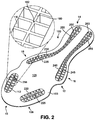
FIG. 2 is a top isometric view of an embodiment of a sole member; -
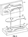
FIG. 3 is a schematic view of an embodiment of a shaping assembly for forming protruding portions on a plate member; -
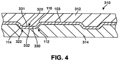
FIG. 4 is a cross sectional view of an embodiment of a shaping assembly with a plate member inserted between a top molding plate and a bottom molding plate; -
FIG. 5 is a top down isometric view of an embodiment of a plate member with a plurality of protruding portions; -
FIG. 6 is an isometric view of a lower surface of an embodiment of a plate member with a plurality of protruding portions; -
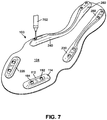
FIG. 7 is a schematic view of an embodiment of holes being formed in a plurality of protruding portions on a plate member; -
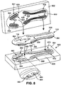
FIG. 8 is a schematic view of an embodiment of a molding assembly for a plate member; -
FIG. 9 is a cross sectional view of an embodiment of a portion of a plate member disposed between a top molding plate and a bottom molding plate; -
FIG. 10 is a cross sectional view of an embodiment of a portion of a plate member disposed between a top molding plate and a bottom molding plate with molding material filled in between the top molding plate and the bottom molding plate; -
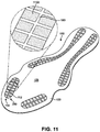
FIG. 11 is an isometric view of an alternative embodiment of a sole structure including filling material; -
FIG. 12 is a cross sectional view of an embodiment of a process of molding material onto a protruding portion without holes; and -
FIG. 13 is an isometric view of an embodiment of a sole structure. - The following discussion and accompanying figures disclose a sole structure for an article of footwear. Concepts associated with the sole structure may be applied to a variety of athletic footwear types, including soccer shoes, running shoes, baseball shoes, basketball shoes, cross-training shoes, cycling shoes, football shoes, golf shoes, tennis shoes, walking shoes, and hiking shoes and boots, for example. The concepts may also be applied to footwear types that are generally considered to be non-athletic, including dress shoes, loafers, sandals, and work boots. Accordingly, the concepts disclosed herein apply to a wide variety of footwear types.
-
FIGS. 1 and2 illustrate isometric views of an embodiment ofsole structure 100. In particular,FIG. 1 illustrates an isometric view of a bottom side ofsole structure 100, whileFIG. 2 illustrates an isometric view of a top side ofsole structure 100. For purposes of illustration,sole structure 100 is shown in isolation inFIGS. 1 and2 . In some embodiments,sole structure 100 could be incorporated into the sole of an article and/or associated with an upper.Sole structure 100 may generally comprise any portion of a sole for an article of footwear. For example, in some cases,sole structure 100 could comprise a portion of an insole. In other cases,sole structure 100 could comprise a portion of a midsole. In one embodiment,sole structure 100 could comprise an outsole for an article that is configured to come into contact with a ground surface. In some embodiments,sole structure 100 may form the entire outsole of an article of footwear. In other embodiments,sole structure 100 may form only a portion of an outsole of an article of footwear. Moreover, in cases wheresole structure 100 comprises an outsole,sole structure 100 could be attached to any other component of a sole structure (such as a midsole or insole). In other cases,sole structure 100 could be attached directly to an upper of an article of footwear. Additionally, in other embodiments, different configurations ofsole structure 100 may be included in an article of footwear. - For purposes of reference, components of
sole structure 100 may be divided intoforefoot portion 10,midfoot portion 12 andheel portion 14.Forefoot portion 10 may be generally associated with the toes and joints connecting the metatarsals with the phalanges.Midfoot portion 12 may be generally associated with the arch of a foot. Likewise,heel portion 14 may be generally associated with the heel of a foot, including the calcaneus bone. In addition,sole structure 100 may includelateral side 16 andmedial side 18. In particular,lateral side 16 andmedial side 18 may be opposing sides ofsole structure 100. Furthermore, bothlateral side 16 andmedial side 18 may extend throughforefoot portion 10,midfoot portion 12 andheel portion 14. - It will be understood that
forefoot portion 10,midfoot portion 12 andheel portion 14 are only intended for purposes of description and are not intended to demarcate precise regions ofsole structure 100. Likewise,lateral side 16 andmedial side 18 are intended to represent generally two sides of a sole structure, rather than precisely demarcatingsole structure 100 into two halves. In addition,forefoot portion 10,midfoot portion 12 andheel portion 14, as well aslateral side 16 andmedial side 18, can also be applied to individual components of a sole structure, such as a sockliner, insole or any other component. - For consistency and convenience, directional adjectives are employed throughout this detailed description corresponding to the illustrated embodiments. The term "longitudinal" as used throughout this detailed description and in the claims refers to a direction extending a length of a component. In some cases, the longitudinal direction may extend from a forefoot portion to a heel portion of the sole structure. Also, the term "lateral" as used throughout this detailed description and in the claims refers to a direction extending a width of the sole structure. In other words, the lateral direction may extend between a medial side and a lateral side of the sole structure. Furthermore, the term "vertical" as used throughout this detailed description and in the claims refers to a direction generally perpendicular to a lateral and longitudinal direction. For example, in cases where a sole structure is planted flat on a ground surface, the vertical direction may extend from the ground surface upward. In addition, the term "proximal" refers to a portion of a footwear component that is closer to a portion of a foot when an article of footwear is worn. Likewise, the term "distal" refers to a portion of a footwear component that is further from a portion of a foot when an article of footwear is worn. It will be understood that each of these directional adjectives may be applied to individual components of an article and/or a sole structure.
- In some embodiments,
sole structure 100 may compriseplate member 103. In some cases,plate member 103 can be a full length plate member, including a forefoot portion, a midfoot portion and a heel portion. In other cases, however,plate member 103 may be a partial length plate member. For example, in some cases,plate member 103 may only extend through the forefoot of an article of footwear. - In some embodiments,
sole structure 100 can include a plurality ofcleat members 102 disposed onlower surface 104 ofplate member 103. Generally, the term "cleat member" as used throughout this detailed specification and throughout the claims includes any provision disposed on a sole structure for increasing traction through friction or penetration of a ground surface. In the current embodiment, plurality ofcleat members 102 includesfirst cleat member 110,second cleat member 120,third cleat member 130,fourth cleat member 140,fifth cleat member 150, andsixth cleat member 160. Although the current embodiment includes six cleat members, in other embodiments,cleat members 102 could include less than six cleat members. In still other embodiments,cleat members 102 could include more than six cleat members. - Generally,
cleat members 102 could be disposed in any arrangement onplate member 103. In some cases, some ofcleat members 102 could be disposed inforefoot portion 10. In other cases, some ofcleat members 102 could be disposed inmidfoot portion 12. In some cases, some ofcleat members 102 could be disposed inheel portion 14. In one embodiment,first cleat member 110 andsecond cleat member 120 are disposed inforefoot portion 10. Also, in one embodiment,third cleat member 130 andfourth cleat member 140 are disposed inmidfoot portion 12. Additionally, in one embodiment,fifth cleat member 150 andsixth cleat member 160 are disposed inheel portion 14. However, any other arrangement ofcleat members 102 are possible. For example, the current embodiment includes cleat members that are disposed on aperipheral portion 106 ofplate member 103. In other cases, however, some cleat members could be disposed more centrally onplate member 103. - It will be understood that the embodiments are not limited to cleat members having a particular shape and/or geometry. For example, some embodiments could incorporate cleat members having different geometries and/or shapes, which may be selected according to various factors including desired traction properties, weight properties, stability properties as well as possible other factors. In some cases, for example, the geometry and/or shape of one or more cleat members could vary according to the intended sport for which
sole structure 100 may be used. In particular, the geometry and/or shape of one or more cleat members could be selected according to whethersole structure 100 is intended for use in football, soccer, baseball, golf as well as possibly other sports, as each sport may be associated with cleats having particular geometric characteristics. - Some embodiments may include provisions for reducing the overall weight of
sole structure 100 while maintaining durability ofcleat members 102. In some cases, for example, a portion of a cleat member could be integrally formed with a plate member. In some cases, a portion of a cleat member can comprise a protruding portion that is integral with a plate member. - In some embodiments,
plate member 103 includes protruding portion 112 (shown in an enlarged cross-section withinFIG. 1 ) that is integrally formed withplate member 103. Protrudingportion 112 may include anouter portion 114 that extends out in a convex manner fromlower surface 104 ofplate member 103. Protrudingportion 112 may also include aninner portion 116 that is recessed in a concave manner with respect toupper surface 105 ofplate member 103. With this configuration, protrudingportion 112 provides an integrally formedfirst portion 118 forfirst cleat member 110 that extends outwardly fromlower surface 104 ofplate member 103. - In some embodiments,
first cleat member 110 further includessecond portion 119. In some cases,second portion 119 comprises first pair ofcleat tip portions 170. First pair ofcleat tip portions 170 includes firstcleat tip portion 171 and secondcleat tip portion 172 that are spaced apart bygap 173. In other embodiments,second portion 119 could include a single cleat tip portion. In still other embodiments,second portion 119 could include three or more distinct cleat tip portions. - In some embodiments,
second portion 119 can also include connectingportion 174. In some cases, connectingportion 174 wraps aroundsidewalls 115 of protrudingportion 112. Connectingportion 174 may be configured to connect firstcleat tip portion 171 with secondcleat tip portion 172. Moreover, in some cases, connectingportion 174 can provide a connection between pair ofcleat tip portions 170 and any other portions ofsole member 100. - A sole member can include provisions for increasing the strength of a protruding portion. In some embodiments, a protruding portion can be configured with a supporting structure. A supporting structure can be any structure configured to reinforce or otherwise enhance support for a protruding portion. In some cases, a supporting structure can also help to anchor one or more cleat tip portions to a protruding portion.
- In some embodiments, protruding
portion 112 can be associated with first supportingstructure 180. In some cases, first supportingstructure 180 may comprise a lattice like structure that is disposed withininner portion 116 of protrudingportion 112. In some cases, first supportingstructure 180 comprises a plurality of intersecting ribs or walls that are arranged approximately along the longitudinal and lateral directions of protrudingportion 112. - In different embodiments, the geometry of supporting
structure 180 can vary. Any three-dimensional geometry and/or two-dimensional geometry could be used for supportingstructure 180. In some cases, supportingstructure 180 has a square or rectangular lattice-like cross-sectional geometry. In other cases, supportingstructure 180 could have a hexagonal lattice-like, or honeycomb shaped, cross-sectional geometry. In still other cases, the cross-sectional geometry could be associated with any other shapes including triangles, rectangles, circles, ellipses, polygons, regular shapes as well as irregular shapes. Moreover, the pattern associated with supportingstructure 180 could be constant or could vary over different regions. It will be understood that the geometry of a supporting structure could be selected according to the desired strength characteristics for a protruding portion as well as the geometry of the protruding portion. - In some embodiments, supporting
structure 180 could extend throughout the substantial entirety ofinner portion 116. In other cases, supportingstructure 180 could extend through only a part ofinner portion 116. In some cases, a supportingstructure 180 could have a variable height that is contoured to fit the shape ofinner portion 116. In some cases,surface 182 of supportingstructure 180 could be approximately flush withupper surface 105 ofplate member 103. - In some embodiments, protruding
portion 112 can includefirst hole 191 andsecond hole 192. In some cases, supportingstructure 180 and first pair ofcleat tip portions 170 can be connected throughfirst hole 191 andsecond hole 192. In some cases, first pair ofcleat tip portions 170 and supportingstructure 180 comprise a substantially continuous material portion that are joined throughfirst hole 191 andsecond hole 192. This arrangement helps to anchor pair ofcleat tip portions 170 to protrudingportion 112. - In some embodiments, each of the remaining cleat members may be configured in a similar manner to
first cleat member 110. For example, each ofsecond cleat member 120,third cleat member 130,fourth cleat member 140,fifth cleat member 150 andsixth cleat member 160 include corresponding protrudingportion 220, protrudingportion 230, protrudingportion 240, protrudingportion 250 and protrudingportion 260, respectively, which may be collectively referred to along with protrudingportion 112 as protrudingportions 280. Each protruding portion includes a corresponding convex outer portion alonglower surface 104 and a corresponding concave inner portion alongupper surface 105. In some cases, protrudingportion 240 and protrudingportion 260 could be continuous with one another, formingintermediate ridge portion 210 onlower surface 104. Likewise, in some cases, protrudingportion 230 and protrudingportion 250 could be continuous with one another, formingintermediate ridge portion 212 onlower surface 104. In other cases, however,plate member 103 may not includeridge portion 210 and/orridge portion 212. - In some embodiments, each of
second cleat member 120,third cleat member 130,fourth cleat member 140,fifth cleat member 150 andsixth cleat member 160 may include corresponding pair oftip portions 226, pair oftip portions 236, pair oftip portions 246, pair oftip portions 256 and pair oftip portions 266, respectively, which may be collectively referred to along with pair oftip portions 170 as plurality ofcleat tip portions 286. In other embodiments, some cleat members can include cleat tip portions, while others may not include cleat tip portions. In other words, in some cases, cleat tip portions may be optional. - In some embodiments, each of
second cleat member 120,third cleat member 130,fourth cleat member 140,fifth cleat member 150 andsixth cleat member 160 may include corresponding connectingportion 228, connectingportion 238, connectingportion 248, connectingportion 258 and connectingportion 268, respectively, which may be collectively referred to along with connectingportion 174 as plurality of connectingportions 290. In other embodiments, some cleat members can include connecting portions, while others may not include connecting portions. In other words, in some cases, connecting portions may be optional. - In some embodiments, each of
cleat members 102 can also include a corresponding supporting structure. For example, in some cases,second cleat member 120,third cleat member 130,fourth cleat member 140,fifth cleat member 150 andsixth cleat member 160 may include corresponding supportingstructure 225, supportingstructure 235, supportingstructure 245, supportingstructure 255 and supportingstructure 265, respectively, which may be referred to collectively as plurality of supportingstructures 296. In other embodiments, some cleat members can include supporting structures, while others may not include supporting structures. In other words, in some cases, supporting structures may be optional. - Using this arrangement, each cleat member can be configured in a similar manner. In particular, each cleat member comprises a first portion that is integrally formed with a plate member and provides a base like protruding portion for the cleat. Additionally, each cleat member comprises a second portion that is attached to the first portion, where the second portion comprises cleat tip portions that further enhance the traction provided by the cleat member. Moreover, to reduce weight and maintain strength for each cleat member, each cleat member is formed with a hollow inner portion that is filled with a supporting structure. For example, plurality of protruding
portions 280 are filled with plurality of supportingstructures 296. The supporting structures help increase the structural integrity of the cleat member and can provide anchoring forcleat tip portions 286. - In some embodiments, plurality of
cleat tip portions 286 may be integrally formed with plurality of connectingportions 290. Moreover, each of connectingportions 290 can be connected toperipheral layer 298 that extends aroundperipheral portion 106 ofplate 103 onlower surface 104. In some cases, as discussed in further detail below, plurality ofcleat tip portions 286, plurality of connectingportions 290 andperipheral layer 298 may comprise a single molded layer that is disposed overlower surface 104 ofplate member 103. In other cases, however, some of these various portions may not be connected to one another. -
FIGS. 3 through 10 are intended to illustrate one embodiment of a process for making a sole structure including integrated cleat members. In some embodiments, some of the steps associated with the process could be accomplished by a proprietor, a manufacturer, a retailer or any other entity. It will be understood that in some embodiments one or more of the steps associated with the process may be optional. In other embodiments, some additional steps could be included that are not discussed below. Additionally, the order of the steps discussed below could be rearranged in any desired manner. - In different embodiments,
plate member 103 can comprise different materials with different characteristics. In some embodiments,plate member 103 can comprise a composite material. The term "composite material" as used throughout this detailed description and in the claims, refers to any material made from two or more materials with differing material properties that retain some amount of separation within the composite material. In some cases,plate member 103 may be made of a fiber-reinforced composite material including short fiber-reinforced materials and continuous fiber-reinforced materials. Examples of fiber-reinforced materials include, but are not limited to: wood, carbon-fiber reinforced plastics and glass reinforced plastics. In one embodiment,plate member 103 comprises a carbon fiber reinforced composite. An exemplary composite structure is disclosed in Auger,U.S. Patent Number 7,832,117, issued November 16, 2010 . In other cases, however,plate member 103 could be made of any other materials, including materials with relatively high rigidities or materials with relatively low rigidities. - In some cases,
cleat tip portions 286, connectingportions 290 and/or supportingstructures 296 may comprise substantially similar materials. Examples of materials that could be used for these components include, but are not limited to: plastics, rubbers, metals as well as any other materials. In one embodiment, each ofcleat tip portions 286, connectingportions 290 and supportingstructures 296 may comprise a relatively soft and/or flexible plastic material, such as thermoplastic polyurethane (TPU). In other embodiments, these different portions could comprise different materials. For example,cleat tip portions 286 and supportingstructures 296 could be made of substantially different plastic materials. - The arrangement described above provides an integrated cleat member with a strong base (a protruding portion) that is integrally formed with substantially rigid composite plate. This arrangement further provides a cleat member with a more flexible cleat tip that provides for adaptability of the cleat tip on different kinds of surfaces and enhances penetration into a ground surface.
-
FIGS. 3 and4 illustrate schematic views of an embodiment of a process for forming a plurality of protruding portions on a plate member. Initially, as seen inFIG. 3 ,plate member 103 could be associated with shapingassembly 310. Initially,plate member 103 could be configured with any geometry. In some cases,plate member 103 may have any approximately two-dimensional geometry, such that the width and length are substantially greater than the depth ofplate member 103. In other cases, the depth ofplate member 103 could vary such thatplate member 103 is better described as three-dimensional. In some embodiments,plate member 103 could have a substantially flat geometry. For example, in one embodiment,plate member 103 comprises a substantially flat layer. In other embodiments, however,plate member 103 could have a curved or contoured geometry. For example, in some cases,plate member 103 could be pre-shaped with the geometry of an outsole including a contoured periphery that slopes upwardly towards a midsole component or upper of an article of footwear. - As seen in
FIG. 3 , in an exemplary embodiment,plate member 103 may have a substantially flat geometry without any protrusions. In some cases, the geometry ofplate member 103 could be slightly contoured. Additionally, in some cases,plate member 103 could be pre-shaped to have anouter edge 302 that has the approximate shape of an outsole or other sole component. - It will be understood that in other embodiments, rather than starting with a substantially
flat plate member 103, other embodiments of the method could start with a stock material that needs to be re-shaped and also cut. For example, in some cases, a rectangular sheet of stock composite material may be shaped usingshaping assembly 310 and then cut to the shape of an outsole or other sole component. - Shaping
assembly 310 can be any machine or device known in the art for shaping or otherwise deforming various different kinds of materials including rigid materials. In some cases, shapingassembly 310 comprises a press that is configured to re-shape one or more portions of a rigid material using pressure and/or heat. In particular, shapingassembly 310 could include a top molding portion and a bottom molding portion that are used to reshape a rigid material. In some embodiments, shapingassembly 310 may use pressure to reshape portions ofplate member 103. In some cases, shapingassembly 310 may use heat to reshape portions ofplate member 103. In some cases, shapingassembly 310 may use heat and pressure to reshape portions ofplate member 103. In one embodiment, shapingassembly 310 could be part of a device that uses an autoclave molding technique to shape composite materials. - In one embodiment, shaping
assembly 310 comprisestop molding plate 312 andbottom molding plate 314. In some cases,top molding plate 312 andbottom molding plate 314 provide molding surfaces that can be used to reshape on one or more portions ofplate member 103. In some cases,top molding plate 312 could be provided withprotrusions 320. Additionally,bottom molding plate 314 could be provided withrecesses 322 that correspond withprotrusions 320. As seen inFIGS. 3 and4 , to form protrusions inplate member 103,protrusions 320 and recesses 322 oftop molding plate 312 andbottom molding plate 314 may be aligned on opposing sides ofplate member 103. Astop molding plate 312 andbottom molding plate 314 are pressed together, protrudingportions 280 are formed. For example, in one embodiment,first portion 330 ofplate member 103 is aligned with first protrudingportion 331 oftop molding plate 312 andfirst recess 332 ofbottom molding plate 314. Astop mold 312 and bottom bold 314 are pressed together,first portion 330 is reshaped to form first protrudingportion 112, including concaveinner portion 116 and convexouter portion 114. - Each of the remaining protruding portions discussed above, including second protruding
portion 220, third protrudingportion 230, fourth protrudingportion 240, fifth protrudingportion 250 and sixth protruding portion 260 (seeFIG. 1 ) can be formed in a similar manner using correspondingprotrusions 320 and recesses 322 of shapingassembly 310. Although the current embodiment illustrates a process for forming a plurality of protruding portions simultaneously, in other embodiments two or more different protrusions can be formed during different steps. For example, in some cases, protruding portions can be formed one at a time by applying a shaping assembly to a localized region of a plate member. - It will be understood that in still other embodiments, a plate member or similar sole component could be molded from a liquid and/or foam molding material. For example, in some other cases, a molding assembly can be used to form a sole component from a rubber and/or plastic material.
-
FIGS. 5 and6 illustrate isometric views ofupper surface 105 andlower surface 104, respectively, ofplate member 103 after being removed from shapingassembly 310. As seen inFIGS. 5 and6 ,plate member 103 has been reshaped and includes protrudingportions 280 that extend outwardly fromlower surface 104. At this stage in the process,plate member 103 includes first protrudingportion 112, second protrudingportion 220, third protrudingportion 230, fourth protrudingportion 240, fifth protrudingportion 250 and sixth protrudingportion 260. Each protruding portion includes a corresponding inner concave portion and outer convex portion. For example, first protrudingportion 112 includesinner portion 114 andouter portion 116. -
FIG. 7 illustrates an embodiment of a possible step in the method where holes are formed in one or more protruding portions. In one embodiment, two holes are formed in each protruding portion. For example, in the current embodiment,first hole 191 andsecond hole 192 are formed in first protrudingportion 112. In some cases,first hole 191 andsecond hole 192 may extend through the entire thickness of first protrudingportion 112. This allows fluid communication betweenouter portion 114 andinner portion 116, as seen inFIG. 1 . As seen inFIG. 7 , holes may also be formed in each of second protrudingportion 220, third protrudingportion 230, fourth protrudingportion 240, fifth protrudingportion 250 and sixth protrudingportion 260. - Although the current embodiment includes two holes for each protruding portion, in other embodiments any other number of holes could be used. In some cases, each protruding portion could include a single hole. In still other cases, each protruding portion could include more than two holes. Moreover, in some cases, some protruding portions could include holes, while other protruding portions may not include holes.
- Generally, the shape and/or size of a hole can vary. In some embodiments, each hole may have an approximately circular shape. In other cases, however, each hole could have any other shape including, but not limited to: triangular shapes, rectangular shapes, oval shapes, polygonal shapes, regular shapes and/or irregular shapes. In addition, the size of each hole could be varied in any manner.
- Methods for forming holes in a plate member can vary. In one embodiment, each hole may be formed using
water jet cutter 702 that uses high pressure and high velocity water to cut through rigid materials. In other embodiments, however, holes could be formed using any other techniques known in the art including, but not limited to laser cutting techniques, drilling and punching. In still other embodiments, holes could be formed simultaneously with a protruding portion. For example, in an embodiment where a portion of a plate member is reshaped to form a protruding portion, a hole could be punched from the plate member as the protruding portion is being formed using a molding plate. -
FIGS. 8 - 10 illustrate embodiments of a method of forming cleat tip portions and support structures on a plate member. In particular,FIG. 8 illustrates a schematic view ofplate member 103 inserting intomolding assembly 800, whileFIGS. 9 and 10 illustrate cross sectional views of a protruding portion inside a portion ofmolding assembly 800. - Referring to
FIG. 8 ,molding assembly 800 comprisestop molding plate 802 andbottom molding plate 804. For purposes of illustration,molding assembly 800 is shown schematically in the current embodiment, however it will be understood thatmolding assembly 800 can be representative of any type of molding device, machine or system known in the art. - In some embodiments,
top molding plate 802 is configured with provisions for forming supporting structures. In one embodiment,top molding plate 802 includesspacer portions 820.Spacer portions 820 comprise projections that extend outwardly fromtop molding plate 802. In some cases,spacer portions 820 are integrally formed withtop molding plate 802. For example, in embodiments wheretop molding plate 802 comprises a metal material,spacer portions 820 may comprise a substantially similar metal material. In other cases, however, spacerportions 820 may not be integrally formed withtop molding plate 802. In some other embodiments, for example,spacer portions 820 could be removable fromtop molding plate 802. - In some embodiments,
spacer portions 820 are arranged in sets that correspond with each protruding portion ofplate member 103. For example, first set ofspacer portions 822 are configured to insert intoinner portion 116 of first protrudingportion 112, as shown inFIG. 9 . Likewise, second set ofspacer portions 824, third set ofspacer portions 826, fourth set ofspacer portions 828, fifth set ofspacer portions 830 and sixth set ofspacer portions 832 are configured to insert into second protrudingportion 220, third protrudingportion 230, fourth protrudingportion 240, fifth protrudingportion 250 and sixth protrudingportion 260, respectively. - Each set of spacer portions may be configured to create a corresponding supporting structure during a molding process. For example, first set of
spacer portions 822 includes spacer portions approximately aligned in two longitudinal rows and eight lateral rows. The spacer portions are separated bygaps 831 where molding material may be filled in between the spacer portions. - In some embodiments, the geometry of each spacer portion can be varied. In some embodiments, the shape of each spacer portion can be contoured so that each set of spacer portions has an overall shape corresponding to the approximate shape of an associated protruding portion. For example, in one embodiment, the spacer portions of first set of
spacer portions 822 include contouredouter edges 840 that are contoured to the shape ofouter edge 850 of first protrudingportion 112. In some cases, the heights of one or more spacer portions could be constant. In other cases, the heights of one or more spacer portions could be varied to accommodate the contours of first protrudingportion 112. In the current embodiment, the spacer portions of the majority of first set ofspacer portions 822 have approximately constant heights. In this case, theoutermost spacer portions 839 have shorter heights to accommodate the slope ofinner portion 116, as seen inFIG. 9 . - In some embodiments,
bottom molding plate 804 includes provisions for forming cleat tip portions onlower surface 104 ofplate member 103. In one embodiment,bottom molding plate 804 includesmolding cavities 860.Molding cavities 860 comprise recesses that are sunken in fromupper surface 805 ofbottom molding plate 804.Molding cavities 860 may includefirst molding cavity 862,second molding cavity 864,third molding cavity 866,fourth molding cavity 868,fifth molding cavity 870 andsixth molding cavity 872, corresponding to first protrudingportion 112, second protrudingportion 220, third protrudingportion 230, fourth protrudingportion 240, fifth protrudingportion 250 and sixth protrudingportion 260, respectively. - In some embodiments, each molding cavity may be shaped to form corresponding cleat tip portions and connecting portions on a protruding portion. For example,
first molding cavity 862 can include recessedportion 880 that may receivesidewall portions 115 of first protrudingportion 112. In addition,first molding cavity 862 further includesfirst sub-recess 882 andsecond sub-recess 884, which are recessed with respect to recessedportion 880. First sub-recess 882 andsecond sub-recess 884 may be shaped to form firstcleat tip portion 171 and secondcleat tip portion 172 offirst cleat member 110, as shown inFIG. 1 . - Each of the remaining
molding cavities 860 can be configured in a substantially similar manner tofirst molding cavity 862. In particular, each ofsecond molding cavity 864,third molding cavity 866,fourth molding cavity 868,fifth molding cavity 870 andsixth molding cavity 872 can include similar recessed portions to form cleat tip portions and connecting portions on second protrudingportion 220, third protrudingportion 230, fourth protrudingportion 240, fifth protrudingportion 250 and sixth protrudingportion 260, respectively. - In some embodiments,
bottom molding plate 804 can also includeperipheral cavity 890 that extends betweenmolding cavities 860.Peripheral cavity 890 may be a relatively shallow cavity that is used to form peripheral layer 298 (seeFIG. 1 ). In other embodiments,bottom molding plate 804 may not includeperipheral cavity 890. - Referring to
FIG. 9 , withplate member 103 placed withinmolding assembly 800, first set ofspacer portions 822 oftop molding plate 802 are inserted intoinner portion 116 of first protrudingportion 112. Likewise, first protrudingportion 112 is disposed withinfirst molding cavity 862 ofbottom molding plate 804. At this point,injection nozzle 900 may be aligned with an injectingport 902 oftop molding plate 802. - For purposes of clarity, the current embodiment illustrates an
injection port 902 associated withtop molding plate 802 in the region of first set ofspacer portions 822. However, in other embodiments, an injection port could be associated with any other portion ofmolding assembly 800, includingtop molding plate 802 and/orbottom molding plate 804. Also, in some cases, multiple injection ports can be used at multiple locations ofmolding assembly 800. For example, in one embodiment, each set of spacer portions oftop molding plate 802 could include a separate injection port. In other cases, each molding cavity ofbottom molding plate 804 could include a separate injection port. - Next, as shown in
FIG. 10 ,molding material 1000 injected through first set ofspacer portions 822. This allows the molding material to fill intogaps 831 to form first supportingstructure 180. Moreover,molding material 1000 may flow throughfirst hole 191 andsecond hole 192 of protrudingportion 112 intomolding cavity 862. Thus,molding material 1000 is able to coversidewall portions 115 of first protrudingportion 112 to form first connectingportion 174. Also,molding material 1000 may fill intofirst sub-recess 882 andsecond sub-recess 884 in order to form firstcleat tip portion 171 and secondcleat tip portion 172. - As previously discussed,
molding material 1000 could comprise any material. In some cases,molding material 1000 comprises a plastic material, such as thermoplastic polyurethane (TPU). In other cases, however,molding material 1000 could be any other material.Molding material 1000 could be selected to achieve desired material properties for cleat tip portions and connecting portions of a cleat member. -
FIG. 11 illustrates an alternative embodiment ofsole structure 100 in which the gaps of supportingstructure 180 have been filled withmaterial 1102. In some cases,material 1102 can be inserted into supportingstructure 180 aftersupport structure 180 has been formed. In other cases, however,material 1102 could be formed substantially simultaneously withsupport structure 180, for example using a multi-shot molding process. - Generally,
material 1102 could be any material. In some cases,material 1102 could be a foam material. In other cases,material 1102 could be a plastic material.Material 1102 may be selected in order to achieve desired characteristics forcleat member 110. For example, to increase strength and rigidity forcleat member 110,material 1102 could be a relatively rigid material. In other cases, to increase cushioning,material 1102 could be a foam or soft plastic material. -
FIG. 12 illustrates a cross sectional view of an embodiment of an optional step of a process for making a cleat member. Referring toFIG. 12 , in some embodiments, a protrudingportion 1312 of aplate member 1303 may be formed without any holes. In such cases,molding assembly 800 can include afirst injection nozzle 1302 and asecond injection nozzle 1304 associated withtop molding plate 802 andbottom molding plate 804. This allows afirst material 1322 to be injected intoinner portion 1316 of protrudingportion 1312 and asecond material 1324 to be injected overouter portion 1314 of protrudingportion 1312. - In some embodiments,
first material 1322 andsecond material 1324 could be substantially different materials. In some cases, for example,first material 1322 could be substantially more rigid thansecond material 1324. In other cases,second material 1324 could be substantially more rigid thanfirst material 1322. In still other cases,first material 1322 andsecond material 1324 could be substantially similar materials. For example, in one embodiment,first material 1322 andsecond material 1324 could both be TPU. - Although the current embodiment illustrates a single layer of material on
outer portion 1314 of protrudingportion 1312, other embodiments could incorporate two or more layers. For example, another embodiment may use two layers onouter portion 1314, where the outermost layer could be substantially more abrasion resistant than the layer directly adjacent toouter portion 1314. - As seen in
FIG. 13 , the process shown inFIG. 12 provides a method of making asole structure 1400 withcleat member 1410.Cleat member 1410 includescleat tip portions 1470 and connectingportion 1474 onouter portion 1314 of protrudingportion 1312 associated withouter surface 1304 ofplate member 1303. Moreover, supportingstructure 1480 is formed on aninner portion 1316 of protrudingportion 1312. Moreover, in contrast to the previous embodiments,cleat tip portions 1470 are not connected to supportingstructure 1480. - While various embodiments have been described, the description is intended to be exemplary. Accordingly, the current embodiments are not to be restricted except in light of the attached claims. Features described in one embodiment may or may not be included in other embodiments described herein. Also, various modifications and changes may be made within the scope of the attached claims.
Claims (12)
- A sole structure (100), comprising:a plate member (103) comprising a first material, the plate member (103) having a upper surface and a lower surface;at least one cleat member (110) disposed on the lower surface of the plate member, wherein each of the at least one cleat member includes:a first portion that is integrally formed with the plate member and includes a concave inner portion (116) on the upper surface of the plate member, a convex outer portion (114) on the lower surface of the plate member and a sidewall;a second portion (119) attached to the first portion, the second portion comprising a second material, and including at least one cleat tip portion (171,172) and a connecting portion (174) wrapping around the sidewall of the first portion;a support structure (180) filling at least a portion of the concave inner portion, the support structure forming a lattice-like structure (831) of intersecting walls with gaps between the intersecting walls, and being made of a third material; andwherein the first material is substantially more rigid than the second material andwherein the first material is substantially more rigid than the third material.
- The sole structure according to claim 1, wherein the second material and the third material are substantially similar.
- The sole structure according to claim 1, wherein the first material is a carbon fiber composite material.
- The sole structure according to claim 1, wherein the second material is thermoplastic polyurethane.
- The sole structure according to claim 1, wherein the third material is thermoplastic polyurethane.
- The sole structure according to claim 1, wherein the first portion includes a hole providing fluid communication between the outer portion and the inner portion, and wherein the second portion is attached to the supporting structure through the hole.
- The sole structure set forth in claim 1, wherein the at least one cleat tip portion of each of the at least one cleat member includes a first cleat tip portion and a second cleat tip portion that are spaced from each other by a gap, with the connecting portion of the at least one cleat tip portion connecting the first cleat tip portion and the second cleat tip portion.
- The sole structure set forth in claim 7, wherein the first portion includes at least one hole providing fluid communication between the convex outer portion and the concave inner portion of the first portion, and wherein the at least one cleat tip portion and the supporting structure comprise a substantially continuous material portion joined through the at least one hole.
- The sole structure set forth in claim 8, wherein the at least one hole includes a first hole connecting the supporting structure and the first cleat tip portion, and a second hole connecting the supporting structure and the second cleat tip portion.
- The sole structure set forth in claim 1, wherein the gaps in the lattice structure of the supporting structure are filled with a fourth material.
- The sole structure set forth in claim 10, wherein the fourth material is different than the third material.
- The sole structure set forth in claim 1, wherein the second material and the third material are the same material.
Applications Claiming Priority (3)
| Application Number | Priority Date | Filing Date | Title |
|---|---|---|---|
| US13/487,962 US9615621B2 (en) | 2012-06-04 | 2012-06-04 | Sole structure with integrated cleat member and methods of making |
| EP13736682.9A EP2854586B1 (en) | 2012-06-04 | 2013-05-31 | Sole structure with integrated cleat member and methods of making |
| PCT/US2013/043550 WO2013184497A2 (en) | 2012-06-04 | 2013-05-31 | Sole structure with integrated cleat member and methods of making |
Related Parent Applications (1)
| Application Number | Title | Priority Date | Filing Date |
|---|---|---|---|
| EP13736682.9A Division EP2854586B1 (en) | 2012-06-04 | 2013-05-31 | Sole structure with integrated cleat member and methods of making |
Publications (2)
| Publication Number | Publication Date |
|---|---|
| EP3295816A1 EP3295816A1 (en) | 2018-03-21 |
| EP3295816B1 true EP3295816B1 (en) | 2019-03-27 |
Family
ID=48783331
Family Applications (2)
| Application Number | Title | Priority Date | Filing Date |
|---|---|---|---|
| EP13736682.9A Active EP2854586B1 (en) | 2012-06-04 | 2013-05-31 | Sole structure with integrated cleat member and methods of making |
| EP17001725.5A Active EP3295816B1 (en) | 2012-06-04 | 2013-05-31 | Sole structure with integrated cleat member |
Family Applications Before (1)
| Application Number | Title | Priority Date | Filing Date |
|---|---|---|---|
| EP13736682.9A Active EP2854586B1 (en) | 2012-06-04 | 2013-05-31 | Sole structure with integrated cleat member and methods of making |
Country Status (5)
| Country | Link |
|---|---|
| US (3) | US9615621B2 (en) |
| EP (2) | EP2854586B1 (en) |
| JP (2) | JP6125623B2 (en) |
| CN (1) | CN104540409B (en) |
| WO (1) | WO2013184497A2 (en) |
Families Citing this family (35)
| Publication number | Priority date | Publication date | Assignee | Title |
|---|---|---|---|---|
| US9545129B2 (en) * | 2011-03-08 | 2017-01-17 | Athalonz, Llc | Baseball shoe with cleat pattern for pitching |
| US9839255B2 (en) * | 2012-06-20 | 2017-12-12 | Nike, Inc. | Sole structure for article of footwear |
| US10391705B2 (en) * | 2014-05-09 | 2019-08-27 | Nike, Inc. | System and method for forming three-dimensional structures |
| US10016919B2 (en) * | 2014-07-03 | 2018-07-10 | Nike, Inc. | Method of making an article of footwear with a segmented plate |
| US9930934B2 (en) * | 2014-07-03 | 2018-04-03 | Nike, Inc. | Article of footwear with a segmented plate |
| DE102014115609B4 (en) * | 2014-10-27 | 2017-01-05 | Teng-Jen Yang | A method for producing a simultaneously associated with shoe spikes shoe bottom construction and a corresponding shoe bottom construction with shoe spikes |
| USD735982S1 (en) * | 2014-12-23 | 2015-08-11 | Nike, Inc. | Shoe outsole |
| US9775401B2 (en) | 2015-01-16 | 2017-10-03 | Nike, Inc. | Sole system for an article of footwear incorporating a knitted component with a one-piece knit outsole |
| US10568383B2 (en) | 2015-01-16 | 2020-02-25 | Nike, Inc. | Sole system for an article of footwear incorporating a knitted component with a one-piece knit outsole and a tensile element |
| US9820530B2 (en) | 2015-01-16 | 2017-11-21 | Nike, Inc. | Knit article of footwear with customized midsole and customized cleat arrangement |
| US9848673B2 (en) | 2015-01-16 | 2017-12-26 | Nike, Inc. | Vacuum formed knit sole system for an article of footwear incorporating a knitted component |
| US9820529B2 (en) * | 2015-02-20 | 2017-11-21 | Nike, Inc. | Asymmetric torsion plate and composite sole structure for article of footwear |
| US10244815B2 (en) | 2015-08-25 | 2019-04-02 | Nike, Inc. | Footwear sole structure with carrier and frame |
| USD802899S1 (en) * | 2015-10-30 | 2017-11-21 | Reebok International Limited | Shoe |
| US11019879B2 (en) * | 2015-11-18 | 2021-06-01 | Reebok International Limited | Extruded components for articles of footwear and methods of making the same |
| WO2017115417A1 (en) * | 2015-12-28 | 2017-07-06 | 株式会社アシックス | Shoe member, shoe, and method for manufacturing same |
| USD845597S1 (en) * | 2017-03-06 | 2019-04-16 | Adidas Ag | Shoe |
| USD798562S1 (en) * | 2017-04-21 | 2017-10-03 | Nike, Inc. | Shoe outsole |
| USD847477S1 (en) * | 2017-06-29 | 2019-05-07 | Nike, Inc. | Shoe outsole |
| USD864542S1 (en) * | 2017-12-13 | 2019-10-29 | Under Armour, Inc. | Sole structure |
| US20200147911A1 (en) * | 2018-11-14 | 2020-05-14 | Dean Shoes Company Ltd | Manufacturing method of injection molded composite shoe sole and sole thereof |
| JP7217689B2 (en) * | 2018-12-20 | 2023-02-03 | アクシュネット カンパニー | Golf shoe with outsole with full surface traction area |
| JP2020141737A (en) * | 2019-03-04 | 2020-09-10 | 美津濃株式会社 | Outsole structure, manufacturing method therefor, and cleats shoes using outsole structure |
| JP6903088B2 (en) * | 2019-03-27 | 2021-07-14 | 美津濃株式会社 | Manufacturing method of sole structural members |
| US11944158B2 (en) * | 2019-09-03 | 2024-04-02 | Adidas Ag | Sole element |
| USD966678S1 (en) * | 2019-10-11 | 2022-10-18 | Adidas Ag | Shoe |
| USD954411S1 (en) | 2020-07-24 | 2022-06-14 | Nike, Inc. | Shoe |
| USD937550S1 (en) * | 2020-07-24 | 2021-12-07 | Nike, Inc. | Shoe |
| USD952307S1 (en) | 2020-12-18 | 2022-05-24 | Nike, Inc. | Shoe |
| USD946254S1 (en) * | 2020-12-18 | 2022-03-22 | Nike, Inc. | Shoe |
| US20220378150A1 (en) * | 2021-05-28 | 2022-12-01 | Nike, Inc. | Sole structure for article of footwear |
| US20230270208A1 (en) * | 2022-02-28 | 2023-08-31 | Puma SE | Article of footwear having a sole plate with spikes |
| US11937667B2 (en) * | 2022-08-25 | 2024-03-26 | Teng-Jen Yang | Spike structure made of different materials |
| USD1002169S1 (en) * | 2023-02-23 | 2023-10-24 | Nike, Inc. | Shoe |
| USD1012458S1 (en) * | 2023-02-23 | 2024-01-30 | Nike, Inc. | Shoe |
Family Cites Families (45)
| Publication number | Priority date | Publication date | Assignee | Title |
|---|---|---|---|---|
| BE639898A (en) | 1962-11-17 | |||
| FR2261721A1 (en) * | 1974-02-22 | 1975-09-19 | Beneteau Charles | Sole of sports shoe for outdoor use - has deformable protuberances on the base of the sole |
| NO781821L (en) | 1977-07-18 | 1979-01-19 | Adolf Dassler | SPORTS SHOES, ESPECIALLY FOOTBALL SHOES. |
| JPS54138747A (en) | 1978-04-18 | 1979-10-27 | Kohkoku Chem Ind | Method of making shoes |
| FR2423996A1 (en) | 1978-04-27 | 1979-11-23 | Patrick Sa | FOOTBALL SHOE SOLE |
| FR2481088A1 (en) | 1980-04-28 | 1981-10-30 | Patrick Sa | PROCESS AND MOLD FOR THE MANUFACTURE OF A SPORTED SHOE SPOKE SOLE |
| ES8704337A1 (en) | 1984-11-07 | 1987-04-01 | Kloeckner Ferromatik Desma | Sports shoe and methods for making the same |
| JPH0127682Y2 (en) | 1985-10-14 | 1989-08-22 | ||
| DE58903176D1 (en) * | 1988-12-13 | 1993-02-11 | Helmut Mayer | INSERT FOR A SHOE. |
| JPH0636724Y2 (en) | 1989-04-20 | 1994-09-28 | 美津濃株式会社 | shoes |
| DE4123302C2 (en) * | 1991-07-13 | 1994-02-10 | Uhl Sportartikel Karl | Gripping element for sports shoe soles |
| US5367791A (en) * | 1993-02-04 | 1994-11-29 | Asahi, Inc. | Shoe sole |
| NL9500145A (en) * | 1995-01-26 | 1996-09-02 | Carolus Joannes Maria Pijnenbu | Football shoe sole, method of manufacturing a football shoe sole and football shoe thus obtained. |
| US5832636A (en) | 1996-09-06 | 1998-11-10 | Nike, Inc. | Article of footwear having non-clogging sole |
| US6145221A (en) * | 1996-11-12 | 2000-11-14 | Hockerson; Stan | Cleated athletic shoe |
| US6018893A (en) | 1997-04-03 | 2000-02-01 | Adidas International B.V. | Athletic shoe having notched cleats |
| US6016613A (en) | 1997-11-05 | 2000-01-25 | Nike International Ltd. | Golf shoe outsole with pivot control traction elements |
| DE19850449B4 (en) * | 1998-11-02 | 2005-03-03 | Adidas International Marketing B.V. | Studded shoe |
| US6499235B2 (en) | 1999-12-06 | 2002-12-31 | Adidas International B.V. | Cleated footwear |
| US6954998B1 (en) * | 2000-08-02 | 2005-10-18 | Adidas International Marketing B.V. | Chassis construction for an article of footwear |
| DE10118986B4 (en) | 2001-04-18 | 2006-08-10 | Adidas International Marketing B.V. | sole |
| US7047675B2 (en) | 2001-04-18 | 2006-05-23 | Adidas International Marketing B.V. | Detachable cleat system |
| US6973746B2 (en) * | 2003-07-25 | 2005-12-13 | Nike, Inc. | Soccer shoe having independently supported lateral and medial sides |
| JP2005102788A (en) | 2003-09-29 | 2005-04-21 | Mizuno Corp | Sole structure of sport shoe |
| GB0403591D0 (en) | 2004-02-18 | 2004-03-24 | Smith Wayne | Shock absorbing safety stud |
| US7076857B2 (en) | 2004-08-24 | 2006-07-18 | Chi-Hsiung Yang | Method for making foamed products |
| ITMC20040138A1 (en) | 2004-11-23 | 2005-02-23 | Jo System Srl | PROCEDURE AND EQUIPMENT FOR CUTTING AND SHAPING LEATHER SHEETS OR OTHER MODELABLE MATERIALS |
| CA2609635C (en) | 2005-05-30 | 2011-05-10 | Mizuno Corporation | Sole structure for a shoe |
| WO2006129392A1 (en) * | 2005-05-30 | 2006-12-07 | Mizuno Corporation | Sole structure body for shoes |
| DE102005046138A1 (en) | 2005-09-27 | 2007-03-29 | Uhlsport Gmbh | Sports shoe e.g. football shoe, has sole with cleats for contacting surface of lawn or hard court, arranged in interior of bootleg and is covered with insole, where cleats project outwards through holes of bootleg material |
| US7832117B2 (en) | 2006-07-17 | 2010-11-16 | Nike, Inc. | Article of footwear including full length composite plate |
| US20090113766A1 (en) | 2007-11-07 | 2009-05-07 | Nike, Inc. | Article of Footwear with a Water Repelling Member |
| US7562471B2 (en) | 2006-12-04 | 2009-07-21 | Nike, Inc. | Article of footwear with gripping system |
| US7827705B2 (en) | 2007-03-08 | 2010-11-09 | Nike, Inc. | Article of footwear with multiple cleat sizes |
| US7882648B2 (en) * | 2007-06-21 | 2011-02-08 | Nike, Inc. | Footwear with laminated sole assembly |
| US8056267B2 (en) | 2008-05-30 | 2011-11-15 | Nike, Inc. | Article of footwear with cleated sole assembly |
| US9526297B2 (en) * | 2008-11-26 | 2016-12-27 | Ariat International, Inc. | Footwear sole with honeycomb reinforcement shank |
| CN102421316B (en) * | 2009-04-02 | 2015-11-25 | 耐克创新有限合伙公司 | traction elements |
| JP5422251B2 (en) | 2009-04-17 | 2014-02-19 | ヤンマー株式会社 | vehicle |
| US8356428B2 (en) | 2009-10-20 | 2013-01-22 | Nike, Inc. | Article of footwear with flexible reinforcing plate |
| FR2955466B1 (en) | 2010-01-25 | 2012-04-20 | Salomon Sas | IMPROVED SHOE SHOE |
| FR2958506B1 (en) * | 2010-04-07 | 2012-09-21 | Francois Hochart | THERMOFORMABLE SOLE. |
| US8713819B2 (en) * | 2011-01-19 | 2014-05-06 | Nike, Inc. | Composite sole structure |
| US9119438B2 (en) * | 2011-12-05 | 2015-09-01 | Nike, Inc. | Sole member for an article of footwear |
| US9839255B2 (en) * | 2012-06-20 | 2017-12-12 | Nike, Inc. | Sole structure for article of footwear |
-
2012
- 2012-06-04 US US13/487,962 patent/US9615621B2/en active Active
-
2013
- 2013-05-31 JP JP2015516076A patent/JP6125623B2/en active Active
- 2013-05-31 WO PCT/US2013/043550 patent/WO2013184497A2/en active Application Filing
- 2013-05-31 EP EP13736682.9A patent/EP2854586B1/en active Active
- 2013-05-31 EP EP17001725.5A patent/EP3295816B1/en active Active
- 2013-05-31 CN CN201380040990.5A patent/CN104540409B/en active Active
-
2017
- 2017-02-27 US US15/443,230 patent/US10420392B2/en active Active
- 2017-04-05 JP JP2017075301A patent/JP2017119181A/en active Pending
-
2019
- 2019-08-12 US US16/538,082 patent/US11051584B2/en active Active
Non-Patent Citations (1)
| Title |
|---|
| None * |
Also Published As
| Publication number | Publication date |
|---|---|
| US11051584B2 (en) | 2021-07-06 |
| US10420392B2 (en) | 2019-09-24 |
| EP2854586A2 (en) | 2015-04-08 |
| US20190357631A1 (en) | 2019-11-28 |
| EP2854586B1 (en) | 2017-11-01 |
| JP2015518772A (en) | 2015-07-06 |
| JP2017119181A (en) | 2017-07-06 |
| WO2013184497A3 (en) | 2014-01-30 |
| US20130318831A1 (en) | 2013-12-05 |
| WO2013184497A2 (en) | 2013-12-12 |
| CN104540409A (en) | 2015-04-22 |
| JP6125623B2 (en) | 2017-05-10 |
| EP3295816A1 (en) | 2018-03-21 |
| US20170164690A1 (en) | 2017-06-15 |
| US9615621B2 (en) | 2017-04-11 |
| CN104540409B (en) | 2017-05-24 |
Similar Documents
| Publication | Publication Date | Title |
|---|---|---|
| US11051584B2 (en) | Sole structure with integrated cleat member and methods of making | |
| EP3386335B1 (en) | Article having sole assembly with cleats | |
| EP2429326B1 (en) | Article of footwear with vertical grooves | |
| EP2871993B1 (en) | Mold for footwear with sipes and method of manufacturing same | |
| US9468255B2 (en) | Sole structures and articles of footwear having a lightweight midsole member with protective elements | |
| EP3171725B1 (en) | Footwear with sole structure incorporating lobed fluid-filled chamber with protruding end wall portions | |
| EP2874514B1 (en) | Sole plate assembly and method of making | |
| EP3007578B1 (en) | Contoured insoles for footwear | |
| EP2605676B1 (en) | Article of footwear with slots and method of making | |
| US11547180B2 (en) | Sole structure with overmolded cleats | |
| EP1714571A1 (en) | Shoe sole product and method | |
| EP3010364B1 (en) | Method for making a cleated plate member and apparatus | |
| CN105495864A (en) | Method for manufacturing footwear having sipes in shoe soles | |
| EP3267822B1 (en) | Auxetic structures and footwear with soles having auxetic structures | |
| EP3402359B1 (en) | Sole structure for an article of footwear, comprising an outer sole component with a co-molded flex modifier component, and method of making said sole structure | |
| CN111741692B (en) | Sole for shoes | |
| EP2969507B1 (en) | A midsole for an article of footwear formed from two preforms and method and mold for manufacturing same |
Legal Events
| Date | Code | Title | Description |
|---|---|---|---|
| PUAI | Public reference made under article 153(3) epc to a published international application that has entered the european phase |
Free format text: ORIGINAL CODE: 0009012 |
|
| STAA | Information on the status of an ep patent application or granted ep patent |
Free format text: STATUS: THE APPLICATION HAS BEEN PUBLISHED |
|
| AC | Divisional application: reference to earlier application |
Ref document number: 2854586 Country of ref document: EP Kind code of ref document: P |
|
| AK | Designated contracting states |
Kind code of ref document: A1 Designated state(s): AL AT BE BG CH CY CZ DE DK EE ES FI FR GB GR HR HU IE IS IT LI LT LU LV MC MK MT NL NO PL PT RO RS SE SI SK SM TR |
|
| STAA | Information on the status of an ep patent application or granted ep patent |
Free format text: STATUS: REQUEST FOR EXAMINATION WAS MADE |
|
| 17P | Request for examination filed |
Effective date: 20180621 |
|
| RBV | Designated contracting states (corrected) |
Designated state(s): AL AT BE BG CH CY CZ DE DK EE ES FI FR GB GR HR HU IE IS IT LI LT LU LV MC MK MT NL NO PL PT RO RS SE SI SK SM TR |
|
| GRAP | Despatch of communication of intention to grant a patent |
Free format text: ORIGINAL CODE: EPIDOSNIGR1 |
|
| STAA | Information on the status of an ep patent application or granted ep patent |
Free format text: STATUS: GRANT OF PATENT IS INTENDED |
|
| RIC1 | Information provided on ipc code assigned before grant |
Ipc: A43B 13/02 20060101ALI20181029BHEP Ipc: A43B 13/16 20060101ALI20181029BHEP Ipc: A43C 15/16 20060101ALI20181029BHEP Ipc: A43B 5/02 20060101AFI20181029BHEP Ipc: A43B 13/26 20060101ALI20181029BHEP Ipc: B29D 35/12 20100101ALI20181029BHEP Ipc: A43B 13/41 20060101ALI20181029BHEP Ipc: B29D 35/04 20100101ALI20181029BHEP Ipc: A43B 13/12 20060101ALI20181029BHEP Ipc: A43B 13/42 20060101ALI20181029BHEP Ipc: A43B 13/04 20060101ALI20181029BHEP Ipc: A43B 5/14 20060101ALI20181029BHEP Ipc: A43B 5/00 20060101ALI20181029BHEP Ipc: A43B 13/14 20060101ALI20181029BHEP Ipc: A43B 13/22 20060101ALI20181029BHEP Ipc: B29D 35/00 20100101ALI20181029BHEP Ipc: B29D 35/14 20100101ALI20181029BHEP Ipc: A43B 5/06 20060101ALI20181029BHEP |
|
| INTG | Intention to grant announced |
Effective date: 20181113 |
|
| GRAS | Grant fee paid |
Free format text: ORIGINAL CODE: EPIDOSNIGR3 |
|
| GRAA | (expected) grant |
Free format text: ORIGINAL CODE: 0009210 |
|
| STAA | Information on the status of an ep patent application or granted ep patent |
Free format text: STATUS: THE PATENT HAS BEEN GRANTED |
|
| AC | Divisional application: reference to earlier application |
Ref document number: 2854586 Country of ref document: EP Kind code of ref document: P |
|
| AK | Designated contracting states |
Kind code of ref document: B1 Designated state(s): AL AT BE BG CH CY CZ DE DK EE ES FI FR GB GR HR HU IE IS IT LI LT LU LV MC MK MT NL NO PL PT RO RS SE SI SK SM TR |
|
| REG | Reference to a national code |
Ref country code: GB Ref legal event code: FG4D |
|
| REG | Reference to a national code |
Ref country code: CH Ref legal event code: EP |
|
| REG | Reference to a national code |
Ref country code: AT Ref legal event code: REF Ref document number: 1111950 Country of ref document: AT Kind code of ref document: T Effective date: 20190415 |
|
| REG | Reference to a national code |
Ref country code: IE Ref legal event code: FG4D |
|
| REG | Reference to a national code |
Ref country code: DE Ref legal event code: R096 Ref document number: 602013053155 Country of ref document: DE |
|
| PG25 | Lapsed in a contracting state [announced via postgrant information from national office to epo] |
Ref country code: LT Free format text: LAPSE BECAUSE OF FAILURE TO SUBMIT A TRANSLATION OF THE DESCRIPTION OR TO PAY THE FEE WITHIN THE PRESCRIBED TIME-LIMIT Effective date: 20190327 Ref country code: SE Free format text: LAPSE BECAUSE OF FAILURE TO SUBMIT A TRANSLATION OF THE DESCRIPTION OR TO PAY THE FEE WITHIN THE PRESCRIBED TIME-LIMIT Effective date: 20190327 Ref country code: NO Free format text: LAPSE BECAUSE OF FAILURE TO SUBMIT A TRANSLATION OF THE DESCRIPTION OR TO PAY THE FEE WITHIN THE PRESCRIBED TIME-LIMIT Effective date: 20190627 Ref country code: FI Free format text: LAPSE BECAUSE OF FAILURE TO SUBMIT A TRANSLATION OF THE DESCRIPTION OR TO PAY THE FEE WITHIN THE PRESCRIBED TIME-LIMIT Effective date: 20190327 |
|
| REG | Reference to a national code |
Ref country code: NL Ref legal event code: MP Effective date: 20190327 |
|
| PG25 | Lapsed in a contracting state [announced via postgrant information from national office to epo] |
Ref country code: GR Free format text: LAPSE BECAUSE OF FAILURE TO SUBMIT A TRANSLATION OF THE DESCRIPTION OR TO PAY THE FEE WITHIN THE PRESCRIBED TIME-LIMIT Effective date: 20190628 Ref country code: RS Free format text: LAPSE BECAUSE OF FAILURE TO SUBMIT A TRANSLATION OF THE DESCRIPTION OR TO PAY THE FEE WITHIN THE PRESCRIBED TIME-LIMIT Effective date: 20190327 Ref country code: BG Free format text: LAPSE BECAUSE OF FAILURE TO SUBMIT A TRANSLATION OF THE DESCRIPTION OR TO PAY THE FEE WITHIN THE PRESCRIBED TIME-LIMIT Effective date: 20190627 Ref country code: LV Free format text: LAPSE BECAUSE OF FAILURE TO SUBMIT A TRANSLATION OF THE DESCRIPTION OR TO PAY THE FEE WITHIN THE PRESCRIBED TIME-LIMIT Effective date: 20190327 Ref country code: NL Free format text: LAPSE BECAUSE OF FAILURE TO SUBMIT A TRANSLATION OF THE DESCRIPTION OR TO PAY THE FEE WITHIN THE PRESCRIBED TIME-LIMIT Effective date: 20190327 Ref country code: HR Free format text: LAPSE BECAUSE OF FAILURE TO SUBMIT A TRANSLATION OF THE DESCRIPTION OR TO PAY THE FEE WITHIN THE PRESCRIBED TIME-LIMIT Effective date: 20190327 |
|
| REG | Reference to a national code |
Ref country code: AT Ref legal event code: MK05 Ref document number: 1111950 Country of ref document: AT Kind code of ref document: T Effective date: 20190327 |
|
| PG25 | Lapsed in a contracting state [announced via postgrant information from national office to epo] |
Ref country code: IT Free format text: LAPSE BECAUSE OF FAILURE TO SUBMIT A TRANSLATION OF THE DESCRIPTION OR TO PAY THE FEE WITHIN THE PRESCRIBED TIME-LIMIT Effective date: 20190327 Ref country code: SK Free format text: LAPSE BECAUSE OF FAILURE TO SUBMIT A TRANSLATION OF THE DESCRIPTION OR TO PAY THE FEE WITHIN THE PRESCRIBED TIME-LIMIT Effective date: 20190327 Ref country code: PT Free format text: LAPSE BECAUSE OF FAILURE TO SUBMIT A TRANSLATION OF THE DESCRIPTION OR TO PAY THE FEE WITHIN THE PRESCRIBED TIME-LIMIT Effective date: 20190727 Ref country code: AL Free format text: LAPSE BECAUSE OF FAILURE TO SUBMIT A TRANSLATION OF THE DESCRIPTION OR TO PAY THE FEE WITHIN THE PRESCRIBED TIME-LIMIT Effective date: 20190327 Ref country code: ES Free format text: LAPSE BECAUSE OF FAILURE TO SUBMIT A TRANSLATION OF THE DESCRIPTION OR TO PAY THE FEE WITHIN THE PRESCRIBED TIME-LIMIT Effective date: 20190327 Ref country code: CZ Free format text: LAPSE BECAUSE OF FAILURE TO SUBMIT A TRANSLATION OF THE DESCRIPTION OR TO PAY THE FEE WITHIN THE PRESCRIBED TIME-LIMIT Effective date: 20190327 Ref country code: EE Free format text: LAPSE BECAUSE OF FAILURE TO SUBMIT A TRANSLATION OF THE DESCRIPTION OR TO PAY THE FEE WITHIN THE PRESCRIBED TIME-LIMIT Effective date: 20190327 Ref country code: RO Free format text: LAPSE BECAUSE OF FAILURE TO SUBMIT A TRANSLATION OF THE DESCRIPTION OR TO PAY THE FEE WITHIN THE PRESCRIBED TIME-LIMIT Effective date: 20190327 |
|
| PG25 | Lapsed in a contracting state [announced via postgrant information from national office to epo] |
Ref country code: SM Free format text: LAPSE BECAUSE OF FAILURE TO SUBMIT A TRANSLATION OF THE DESCRIPTION OR TO PAY THE FEE WITHIN THE PRESCRIBED TIME-LIMIT Effective date: 20190327 Ref country code: PL Free format text: LAPSE BECAUSE OF FAILURE TO SUBMIT A TRANSLATION OF THE DESCRIPTION OR TO PAY THE FEE WITHIN THE PRESCRIBED TIME-LIMIT Effective date: 20190327 |
|
| REG | Reference to a national code |
Ref country code: CH Ref legal event code: PL |
|
| PG25 | Lapsed in a contracting state [announced via postgrant information from national office to epo] |
Ref country code: AT Free format text: LAPSE BECAUSE OF FAILURE TO SUBMIT A TRANSLATION OF THE DESCRIPTION OR TO PAY THE FEE WITHIN THE PRESCRIBED TIME-LIMIT Effective date: 20190327 Ref country code: IS Free format text: LAPSE BECAUSE OF FAILURE TO SUBMIT A TRANSLATION OF THE DESCRIPTION OR TO PAY THE FEE WITHIN THE PRESCRIBED TIME-LIMIT Effective date: 20190727 |
|
| REG | Reference to a national code |
Ref country code: DE Ref legal event code: R097 Ref document number: 602013053155 Country of ref document: DE |
|
| PG25 | Lapsed in a contracting state [announced via postgrant information from national office to epo] |
Ref country code: CH Free format text: LAPSE BECAUSE OF NON-PAYMENT OF DUE FEES Effective date: 20190531 Ref country code: LI Free format text: LAPSE BECAUSE OF NON-PAYMENT OF DUE FEES Effective date: 20190531 Ref country code: DK Free format text: LAPSE BECAUSE OF FAILURE TO SUBMIT A TRANSLATION OF THE DESCRIPTION OR TO PAY THE FEE WITHIN THE PRESCRIBED TIME-LIMIT Effective date: 20190327 Ref country code: MC Free format text: LAPSE BECAUSE OF FAILURE TO SUBMIT A TRANSLATION OF THE DESCRIPTION OR TO PAY THE FEE WITHIN THE PRESCRIBED TIME-LIMIT Effective date: 20190327 |
|
| REG | Reference to a national code |
Ref country code: BE Ref legal event code: MM Effective date: 20190531 |
|
| PLBE | No opposition filed within time limit |
Free format text: ORIGINAL CODE: 0009261 |
|
| STAA | Information on the status of an ep patent application or granted ep patent |
Free format text: STATUS: NO OPPOSITION FILED WITHIN TIME LIMIT |
|
| PG25 | Lapsed in a contracting state [announced via postgrant information from national office to epo] |
Ref country code: SI Free format text: LAPSE BECAUSE OF FAILURE TO SUBMIT A TRANSLATION OF THE DESCRIPTION OR TO PAY THE FEE WITHIN THE PRESCRIBED TIME-LIMIT Effective date: 20190327 Ref country code: LU Free format text: LAPSE BECAUSE OF NON-PAYMENT OF DUE FEES Effective date: 20190531 |
|
| 26N | No opposition filed |
Effective date: 20200103 |
|
| PG25 | Lapsed in a contracting state [announced via postgrant information from national office to epo] |
Ref country code: TR Free format text: LAPSE BECAUSE OF FAILURE TO SUBMIT A TRANSLATION OF THE DESCRIPTION OR TO PAY THE FEE WITHIN THE PRESCRIBED TIME-LIMIT Effective date: 20190327 |
|
| PG25 | Lapsed in a contracting state [announced via postgrant information from national office to epo] |
Ref country code: IE Free format text: LAPSE BECAUSE OF NON-PAYMENT OF DUE FEES Effective date: 20190531 |
|
| PG25 | Lapsed in a contracting state [announced via postgrant information from national office to epo] |
Ref country code: BE Free format text: LAPSE BECAUSE OF NON-PAYMENT OF DUE FEES Effective date: 20190531 |
|
| PG25 | Lapsed in a contracting state [announced via postgrant information from national office to epo] |
Ref country code: CY Free format text: LAPSE BECAUSE OF FAILURE TO SUBMIT A TRANSLATION OF THE DESCRIPTION OR TO PAY THE FEE WITHIN THE PRESCRIBED TIME-LIMIT Effective date: 20190327 |
|
| PG25 | Lapsed in a contracting state [announced via postgrant information from national office to epo] |
Ref country code: MT Free format text: LAPSE BECAUSE OF FAILURE TO SUBMIT A TRANSLATION OF THE DESCRIPTION OR TO PAY THE FEE WITHIN THE PRESCRIBED TIME-LIMIT Effective date: 20190327 Ref country code: HU Free format text: LAPSE BECAUSE OF FAILURE TO SUBMIT A TRANSLATION OF THE DESCRIPTION OR TO PAY THE FEE WITHIN THE PRESCRIBED TIME-LIMIT; INVALID AB INITIO Effective date: 20130531 |
|
| PG25 | Lapsed in a contracting state [announced via postgrant information from national office to epo] |
Ref country code: MK Free format text: LAPSE BECAUSE OF FAILURE TO SUBMIT A TRANSLATION OF THE DESCRIPTION OR TO PAY THE FEE WITHIN THE PRESCRIBED TIME-LIMIT Effective date: 20190327 |
|
| P01 | Opt-out of the competence of the unified patent court (upc) registered |
Effective date: 20230515 |
|
| PGFP | Annual fee paid to national office [announced via postgrant information from national office to epo] |
Ref country code: FR Payment date: 20230411 Year of fee payment: 11 Ref country code: DE Payment date: 20230404 Year of fee payment: 11 |
|
| PGFP | Annual fee paid to national office [announced via postgrant information from national office to epo] |
Ref country code: GB Payment date: 20230406 Year of fee payment: 11 |