EP2854482A1 - Method for generating a sequence of binary code words of a multibit code for a pulse modulated control signal for a consumer - Google Patents
Method for generating a sequence of binary code words of a multibit code for a pulse modulated control signal for a consumer Download PDFInfo
- Publication number
- EP2854482A1 EP2854482A1 EP14155995.5A EP14155995A EP2854482A1 EP 2854482 A1 EP2854482 A1 EP 2854482A1 EP 14155995 A EP14155995 A EP 14155995A EP 2854482 A1 EP2854482 A1 EP 2854482A1
- Authority
- EP
- European Patent Office
- Prior art keywords
- code
- pcm
- der
- die
- oder
- Prior art date
- Legal status (The legal status is an assumption and is not a legal conclusion. Google has not performed a legal analysis and makes no representation as to the accuracy of the status listed.)
- Withdrawn
Links
Images


Classifications
-
- H—ELECTRICITY
- H05—ELECTRIC TECHNIQUES NOT OTHERWISE PROVIDED FOR
- H05B—ELECTRIC HEATING; ELECTRIC LIGHT SOURCES NOT OTHERWISE PROVIDED FOR; CIRCUIT ARRANGEMENTS FOR ELECTRIC LIGHT SOURCES, IN GENERAL
- H05B45/00—Circuit arrangements for operating light-emitting diodes [LED]
- H05B45/30—Driver circuits
- H05B45/345—Current stabilisation; Maintaining constant current
-
- H—ELECTRICITY
- H05—ELECTRIC TECHNIQUES NOT OTHERWISE PROVIDED FOR
- H05B—ELECTRIC HEATING; ELECTRIC LIGHT SOURCES NOT OTHERWISE PROVIDED FOR; CIRCUIT ARRANGEMENTS FOR ELECTRIC LIGHT SOURCES, IN GENERAL
- H05B45/00—Circuit arrangements for operating light-emitting diodes [LED]
- H05B45/30—Driver circuits
- H05B45/32—Pulse-control circuits
Definitions
- the invention relates to a method for generating a sequence of binary codewords of a multi-bit code for a Pulse Code Modulated (PCM) drive signal for a consumer, in particular in its use in a lighting device and in particular in a device for setting multi-colored light scenes in a motor vehicle.
- PCM Pulse Code Modulated
- Electric / electronic consumers can z. B. are controlled quite accurately by pulse modulation.
- the invention in which a PCM modulation is used, is described on the basis of the driving of LEDs as an example of an electronic consumer.
- the PWM modulation has some disadvantages, in particular with regard to EMC aspects, which will be described in detail below.
- Pulse width modulation respectively pulse length modulation (see also " Karsten Block, Peter Busch, Ludger Erwig, Franz Fischer, Wilken Pape, Manfredmgerber: Electrical professions. Learning fields 9-13. Energy and building technology. 1st edition. Academicsverlag EINS, Troisdorf 2006. ISBN 978-3-427-44464-0. P.
- PLM for pulse-length modulation is a type of modulation in which a technical variable (eg the electric current) alternates between two values, whereby the duty cycle of a rectangular pulse is modulated at constant frequency Width of the pulses forming it
- the English term for the method is Pulse Width Modulation (PWM)
- PWM Pulse Width Modulation
- PDM Pulse Width Modulation
- lighting devices are known in the art that include a plurality of light emitters in at least two different colors that are configured to be coupled to a circuit having a current source and a common potential reference and driver (TR1, TR2, TR3, DRV ) for operating the plurality of light emitters, of which at least two are connected to the plurality of light emitters and the circuit and comprise the respective current paths of the at least two differently colored light emitters corresponding switches.
- said prior art lighting device includes control for periodically and independently opening and closing at least two switches.
- the controller has a variable bus address assigned to it from outside in order to identify and respond to the address portion of an input data flow, the data flow portion, in particular an addressed data packet, being assigned to this controller.
- this lighting device of the prior art is characterized in particular in that each light emitter is an LED and the controller generates a plurality of PWM signals, each PWM signal each one of the PWM signals causes a corresponding one of the at least two opening and closing switches with corresponding frequencies according to the respective working cycles and wherein the data flow component data for determining the respective working cycles of the at least two differently colored LEDs includes (see eg EP-B-1 016 062 ).
- Fig. 1 shows an exemplary spectrum for a bipolar PWM according to the prior art.
- an illumination device in which the light sources are operated to generate light of desired intensity and color by means of pulse modulation of a randomly controlled pulse width, which in turn adjusts white noise as a spectrum.
- the invention solves the problem of providing a device for supplying light emitters and / or LEDs with electrical energy, wherein an interference spectrum with reduced amplitude and in contrast to the prior art within certain limits modelable interference spectrum arise.
- a subtask to be given later in the description is the provision of a pseudo-random signal with a fill factor that deviates from 50%.
- the consumers are driven by means of a drive signal which is PCM-coded.
- the codewords of a multi-bit PCM code can be divided into several code classes, sorted by the number of their one-bits. Each code class represents a specific energy / power used by a consumer. If a consumer is to be controlled with a predeterminable energy / power which is assigned to a code class comprising a plurality of code words, their codewords will change according to the invention, in particular stochastically, ie randomly or quasi-randomly controlled, or else used in a deterministically varying manner.
- This has the advantage that the (interference) spectrum to be observed with regard to the EMC can be selected in advance or limited, and thus differs quite clearly from white noise. This, in turn, makes it much easier to take the measures required to ensure EMC, which, moreover, are much easier to implement.
- PCM Pulse Code Modulated
- PCM Pulse Code Modulated
- the Pulse Code Modulated (PCM) drive signals only from such code classes, which comprise a plurality of codewords represent codewords, one with respect to the number n of the bits of the multi-bit code percentage of Have one-bits lying between a predetermined lower and a predetermined upper limit and / or within one or more predetermined ranges.
- a subset of codewords is selected from the number of codewords of a code class, and that the codewords of this subset are used to form the Pulse Code Modulated (PCM) drive signal.
- PCM Pulse Code Modulated
- each Pulse Code Modulated (PCM) drive signal representing a codeword has a partial spectrum in the frequency domain and thus corresponds to a partial spectrum of each codeword of each code class and that those codewords whose partial spectra lie within a predeterminable overall spectrum, potentially be used for the formation of the Pulse Code Modulated (PCM) drive signal.
- PCM Pulse Code Modulated
- the clock frequency of the PCM drive signals, with which the code words are transmitted monofrequent or bandwidth limited with a lower limit frequency not equal to zero and an upper limit frequency and thus variable.
- one or more codewords of one or at least one other code class can be transmitted within a temporal sequence of codewords of a code class.
- a modification i. H. "sprinkling" codewords of code classes other than those representing the electrical voltage, electrical current, or electrical power with which the consumer is to be currently supplied may be advantageous in terms of the above-mentioned property limitations of a consumer.
- the at least two PCM drive signals do not correlate and / or only after a predefinable number of clocks, z. B. only after 256, 512, 1024, 2048 or 4096 cycles for one or a few bars each other. This measure serves to suppress the formation and / or the effects of disturbances.
- an expedient embodiment of the invention may also be provided to control the consumer, where appropriate, in addition to the PCM control with respect to the size of the supplied electrical power specifically or to regulate.
- This will be explained below with reference to an LED as a consumer, in which the drive unit controls the color temperature of the LED based on a desired and an actual color temperature value by the maximum current and / or the maximum voltage and / or the maximum energy of the respective PCM drive signal is controlled , As a result, the supply of the consumer with electrical power, adapted to its potential “property losses" and thus these are compensated.
- the background of this measure is that a consumer can react differently when being driven by the PCM signals with code words from the same code class.
- the load operates according to the codeword and succession of the one-bits for a different amount of time with the operating voltage defined by a one-bit or the corresponding operating current. This can z. B. have influence on the color temperature of lamps and in particular LEDs.
- this effect is corrected by a variable value (represented by a one-bit of the code) for the voltage, current or power to be supplied to the load.
- a variable value represented by a one-bit of the code
- the above finding can also be used to exclude those code words of a code class for a drive whose one-bit pattern for the operation of a consumer are less advantageous than other one-bit patterns of this class of code.
- the inventive method is particularly suitable for supplying at least one electrical / electronic such.
- an electromechanical, electro-optical or electro-acoustic consumer in particular a light source such.
- a light source such.
- an LED or a consumer with a possibly parasitic, ohmic and / or inductive and / or capacitive load, as in electrical / electronic articles / components in the automotive sector and / or daily life for z.
- electrical energy As residential and / or industrial buildings, accessories, transport are encountered, with electrical energy.
- the invention solves the problem of uncontrolled EMC emissions through the use of random bit sequences or pseudo random bit sequences.
- Such random sequences and pseudorandom sequences have the property that approximately 50% of the bits are 1 and approximately 50% of the bits are 0.
- a true random sequence is white noise. If such a sequence were used directly for controlling the light sources, in particular LEDs, their luminous intensity would also rush in frequency ranges that are perceived by the human eye. This is not wanted. It is therefore important that the random sequence is band limited. In particular, it is important that the amplitude of the control signal below a lower limit frequency ⁇ u is ideally zero or negligible for the application.
- T clk is the clock period for the shift operation.
- the feedback is done by a simple primitive polynomial.
- T P is the lower limit frequency. It should be noted, however, that such a pseudo-random sequence always has a mean expected value of about 50% for a 1 and thus is not suitable for amplitude control.
- this expectation value is referred to as "fill factor”, since it determines how many 1 bits on average come from how many 0 bits of a PCM codeword.
- the invention solves this sub-task by means of at least two predefinable codes, which are sent at a constant clock rate.
- predefinable codes which are sent at a constant clock rate.
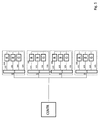
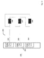
- a controlled device can have a plurality of lighting means (106, 107, 108, R, G, B) which are connected via supply lines (102, 103, 104) to a respective driver (TR1, TR2, TR3, DRV).
- a controller regulates the power and / or the current and / or the voltage which the respective driver (TR1, TR2, TR3, DRV) supplies to the lighting means (106, 107, 108, R, G, B).
- an LED circuit which may consist of parallel and series circuits of LEDs, this is preferably a current drive.
- a voltage or power control is equally useful.
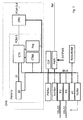
- a PCM (CHN) channel In contrast to the prior art, in each of the drivers (TR1, TR2, Tr3, DRV), a PCM (CHN) channel generates a PCM (Pulse Code Modulation) signal (102, 103, 104) corresponding to a predetermined code, the active code, and the procedure described below.
- CHN PCM
- PCM Pulse Code Modulation
- This active code (in the said example, a 4-bit code) may each be stored in a memory (CTAB) for the exemplary 16 codes resulting from said exemplary 4 bits.
- CTAB memory
- CTAB code table
- the fill factor is the number of 1-bits in a code (in bits) divided by the length of the code (also expressed in bits) as a percentage. The maximum fill factor is therefore 100%.
- a numerical value of 0 of said exemplary 4-control bits is to correspond to a power output of 0% and a fill factor of 0%.
- a numerical value of 16, ie the numerical value of the code, with all 4 bits at logical 1, should correspond to a radiation power of 100% and a filling factor of 100%.
- a 3-bit data word corresponds to the selection of the fill factor, each with a code class.
- a code may have more than 16-bits for the said example, the concrete code being selected, for example, by a 4-bit random number from the set of codes with the same filling factor.
- code class 0 with fill factor 0% with only one code
- code class 1 with fill factor 25% with four codes
- code class 2 with fill factor 50% with six codes
- code class 3 with fill factor 75% with four codes
- code class 4 with fill factor 100% with again only one code (see the right column of the table).
- the exchange can be done, for example, by generating a random or pseudorandom number (ZZ) in a random number generator (ZG), for example as described above, by means of a feedback shift register and a simple primitive polynomial implemented in the form of appropriate logic, for example; but not directly to control the lighting and / or the LED, but to select the active code to be used from the set of allowed and / or possible codes for the next transmission period from the codes of the given code class by a controller (CTR ) and defines this to be used active code.
- the code class corresponds to the desired fill factor. It corresponds in function to that of the duty cycle in a PWM. By selecting the code class, a filling factor for the PCM signal can be determined that deviates substantially from 50%.
- the entire PCM signal generated by the controller becomes a bandlimited aperiodic quasi-random or random signal with a fill factor corresponding to the selected code class appropriate for the driving of the lighting means and especially of LEDs.
- codes within a code class may be restricted due to EMC requirements. So it is conceivable, for example, based on the example discussed here, not to use all six codes with fill factor 50% (see table), but for example only two or even only one of these six possible codes. Using only one code, however, would result in a periodic signal, since then no selection of the code due to the random signal can take place and the PCM signal would lose the property of a random signal.
- a code bit sequence 0010 could thus be transformed to the sequence 0110 in which the first 1 of the sequence is not represented due to the low-pass characteristics of the driver (DRV, TR1, TR2, TR3), the leads (102, 103, 103) and the LEDs (106, 107, 108, R, G, B) so that the desired code 0010 again results as the active code effectively represented by the LEDs.
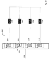
- a lighting device which can be controlled according to the invention therefore typically comprises a plurality of light means and / or LEDs in at least two, but typically three or four or more different colors, in a specific embodiment. These are typically designed to be connected to an electrical power supply.
- the power supply includes an electrical circuit and a common potential reference (105).
- the driver means (TR1, TR2, TR3, DRV) for operating the plurality of light emitters and / or LEDs are also part of the device.
- the driver means (TR1, TR2, TR3, DRV) are connected to the said light sources and / or LEDs and the circuit, and the respective current paths (102, 103, 104) comprise the switches and / or regulators corresponding to at least two differently colored light sources / LEDs , Furthermore, a control for the aperiodic and independent opening and closing of the at least two switches or at least two regulators is provided. In this case, under the opening and closing in the case of a said regulator, a reduction or increase in the energy throughput by the respective controller should be understood.
- the controller is connected to a wired or wireless data network and / or a data line and / or a data bus.
- the controller may have a variable from the outside by means of programming or with the aid of an address generator, which is part of the device variable bus address.
- This bus address is used by the device to z. B. from the data stream data, in particular data packets or other data messages, filter out. It thus identifies the respective proportion of an assigned input data flow and reacts thereto typically by changing a parameter of the device.
- CTAB code or parts of Code table
- CTAB whole code table
- the size of the code table (CTAB) does not necessarily have to be 2 n , where n denotes the length of the code. It is rather conceivable that the code table (CTAB) is implemented much shorter with fewer codes.
- the selection of the active codes is influenced by specifications via the said data interface.
- typically at least two of the luminous means are LEDs.
- the controller (101) typically generates a plurality of PCM signals (102, 103, 104) by means of the drivers (TR1, TR2, TR3).
- the PCM signals (102, 103, 104) do not correlate with each other. This non-correlation may also refer only to portions of the signals. For example, it is conceivable that a correlation only occurs after 256 or 512 or 1024 or 2048 or 4096 clocks, which does not correspond to the technical optimum. Non-corellation is not mandatory.
- Each of the PCM signals (102, 103, 104) corresponds in each case to one color of the plurality of LEDs (106, 107, 108, R, G, B) and / or light sources of different colors.
- each of the PCM signals (102, 103, 104) is generated by in each case at least one corresponding switch or controller associated with the respective PCM signal for opening and closing in accordance with the respective logic state of the internal PCM also associated with the respective PCM signal Signal (PCM-S) of the respective channel (CHN) of the control unit (101) is caused.
- the frequency spectrum of the magnitude of the frequency of the PCM signal is band limited as described above. This means that the signal has a lower limit frequency ⁇ u and / or an upper limit frequency ⁇ o .
- said data flow component determines the data for determining the respective active regions of the transmission codes which emit the at least two differently colored LEDs. It is particularly advantageous if the data flow component, that is to say typically a data packet intended for the device, determines a predefined or preprogrammed color palette in the form of a subset of the possible active codes.
- the device therefore has, per light source, a subdevice which converts the subset of the possible active codes corresponding to this data flow component into a random sequence of on and off signals and in particular into a PCM signal (PCM-S) for the said switch with the preselected fill factor.
- PCM-S PCM signal
- the controller comprises at least two registers for controlling the at least two differently colored lamps / LEDs.
- registers for controlling the at least two differently colored lamps / LEDs.
- parts of registers can be used instead of two registers.
- These registers or register parts are each used to store values which, for example, receives the said data interface from a data flow.
- These data flow components in particular data packets, are then assigned to the respective differently colored lamps / LEDs and, for example, each specify the said fill factor and thus the active code class. This can happen on the one hand in the form that the content of the data flow component directly reflects the fill factor that is to be used or, on the other hand, the contents of the data flow component directly or indirectly refer to the fill factor via further tables, which should be used.
- color palettes are conceivable, which can then refer to the register contents. This is particularly efficient when z. B. a restriction to 16 colors takes place. In this case, not all data, but for example, only a 4-bit data word for the color must be transmitted.
- the fill factor of each individual PCM signal (102, 103, 104, PCM-Out) is then determined using the color palette.
- the invention may conveniently have a controller adapted to adjust the code fill factor appropriately. It will be like described above, which type of code may be used at all.
- the possible filling factors of 0%, 25%, 50%, 75% and 100% of the exemplary code classes 0 to 4 result Filling factors close to the value of 50% each, the maximum number of code variations possible. If this code is sent to a light source or an LED, then the average duty cycle per duty cycle is equal to the product of code transmission time and fill factor. This means that the behavior is analogous to that of a PWM in which the data values for determining the average duty cycle per time unit are assigned to the associated color LEDs (general color lamps).
- the controller comprises at least one further register for the control of the at least two differently colored lamps or LEDs.
- this third register or this third register part is used in each case for storing a third value, which, for example, the said data interface also receives from a data flow.
- the direct use of the value is possible, but also the indirect use of a color palette possibly associated with the code palette.
- the content of the third value refers to the correct code table.
- This data flow component in particular a data packet, is allocated when the active code table is used directly and controls, for example, the selection of the codes from the code table.
- the device It is basically useful to provide the device with a housing which essentially surrounds the plurality of light sources or LEDs, the driver means (TR1, TR2, TR3, DRV) and the said controller (101).
- this includes an electrical regulator for controlling the supplied via the current paths to the plurality of LEDs Maximum currents so as to keep the maximum currents at constant maximum values.
- the amplitude of the PCM pulse signal is also typically controlled.
- the invention can provide a color sensor that allows the control unit (101) to adjust the fill factor and / or the color temperature of the lamps or LEDs so that the desired color emission or color reflection of the irradiated object is achieved.
- the latter comprises an electrical regulator for controlling the maximum energy supplied via the current paths to the plurality of light-emitting means or LEDs so as to keep the maximum energy absorbed by the light-emitting means or LEDs at constant maximum values.
- an electrical regulator for controlling the maximum energy supplied via the current paths to the plurality of light-emitting means or LEDs so as to keep the maximum energy absorbed by the light-emitting means or LEDs at constant maximum values.
- the latter comprises a regulator for controlling the maximum currents or the maximum electrical energy supplied via the current paths to the plurality of LEDs, in order thus to increase the maximum currents and / or maximum energy to constant maximum values
- the housing now essentially surrounds the controller (PWR) in addition to the plurality of LEDs, the driver means (TR1, TR2, TR3, DRV) and the controller (101).
- the controller for identifying and responding to an input data flow component ie the respective data packet, in accordance with a LIN data protocol and / or a Flexray data protocol and / or a CAN data protocol and / or a KNX Data protocol and / or an IP data protocol and / or a USB data protocol and / or an HDMI data protocol.
- a first data interface and a second data interface are available. The transmission from the first data interface to the second data interface should preferably depend on whether the data interface has already received a valid bus address. If this is not the case, the data packets are not forwarded.
- the invention uses a radio interface and / or a Bluetooth interface and / or a WLAN interface.
- each input data flow component advantageously comprises in each case one data word of one or a plurality of bits or bytes for each luminous means or LED color.
- the byte contains 8 data bits for setting the intensity of the respective LED color within a range corresponding to the decimal numbers 0 to 255.
- the controller is set up to control the filling factor of the respectively applied codes in accordance with the bit content of the respective data word.
- a consumer comprises a plurality of red and / or green and / or blue and / or yellow and / or white bulbs or LEDs and / or UV bulbs or LEDs and / or IR bulbs or LEDs.
- the plurality of light sources or LEDs may comprise a serial and / or parallel arrangement of light sources or LEDs.
- Such a device can be used in a lighting network.
- a lighting network comprises a central controller for generating said input data flow and a plurality of lighting devices as described above.
- each of the lighting devices should be arranged to receive the data flow and to set its variable bus address during the initialization phase unlike the other lighting devices of the lighting network and in contrast to the prior art, to ensure that the lighting devices to different proportions of Input data flow react. It is therefore particularly advantageous if each of the lighting devices has a device to generate a variable network address (bus address) itself, which preferably depends on the position in the lighting network. Exemplary methods for this are in DE-B-102 56 631 . EP-B-1 490 772 . EP-B-1 364 288 and / or in EP-A-2 571 200 disclosed.
- the control provides, for example, a bus address to all bus subscribers (lighting device) at the same time and the bus subscribers decide whether this bus address is suitable for the respective bus subscriber. If this decision is positive, the bus user accepts the provided bus address and signals to all other bus users that this bus address has been accepted or that now the assumption of the next bus address should be made by another bus participant.
- This signaling can take place, for example, by passing the data flow from said first data interface of the lighting device to said second data interface of the lighting device and vice versa from the time at which the variable bus address of the lighting device has been adopted.
- the bus address is not concretely assigned to a bus subscriber. It is thus the case that the controller provides the network - ie all bus users - with a bus address for (free) use. Individual bus participants decide independently according to this procedure whether they use this bus address. It is thus not an assignment with respect to a single bus participant, but the assignment of the bus address to a network position.
- the particular advantage of this method is that the individual bus users receive their bus address due to their position and do not have to be preconfigured.
- bus user may also be appropriate for the bus user to maintain the address table of all network addresses (bus addresses) of the lighting network used.
- the bus user selects one of the bus addresses independently, determined by the position in the cable harness.
Abstract
Die Erfindung betrifft ein Verfahren zur Erzeugung einer Sequenz von binären Codewörtern eines Mehrbit-Codes für ein Pulse Modulated Ansteuersignal, wobei bei dem Verfahren - ein Mehrbit-Code mit einer Vielzahl von binären Codewörtern mit jeweils gleicher Anzahl von n-Bits, mit n > 1 bereitgestellt wird, die sich in mindestens zwei Code-Klassen von Codewörtern unterteilen lassen, wobei mindestens eine Code-Klasse mehrere Codewörter mit der gleichen Anzahl von Eins-Bits aufweist und die Anzahl von Eins-Bits der Codewörter der Code-Klassen von Code-Klasse zu Code-Klasse verschieden ist, und - das Pulse Modulated Ansteuersignal als Sequenz der Codewörter einer Code-Klasse erzeugt wird, indem die Codewörter dieser Code-Klasse in dem Pulse Modulated Ansteuersignal zufallsoder quasi zufallsgesteuert oder in beliebig variierender oder deterministisch variierender Reihenfolge aufeinanderfolgen.The invention relates to a method for generating a sequence of binary codewords of a multi-bit code for a pulse-modulated drive signal, wherein in the method - A multi-bit code is provided with a plurality of binary codewords each having the same number of n-bits, with n> 1, which can be divided into at least two code classes of codewords, wherein at least one code class a plurality of codewords with the has the same number of one bits and the number of one bits of the code words of the code classes is different from code class to code class, and - The Pulse Modulated drive signal is generated as a sequence of codewords of a code class in that the code words in the Pulse Modulated drive signal in the Pulse Modulated drive signal randomly or quasi randomly or in any varying or deterministically varying order.
Description
Die Erfindung betrifft ein Verfahren zur Erzeugung einer Sequenz von binären Codewörtern eines Mehrbit-Codes für ein Pulse Code Modulated (PCM-)Ansteuersignal für einen Verbraucher, insbesondere in ihrer Anwendung bei einer Beleuchtungsvorrichtung und insbesondere bei einer Vorrichtung zur Einstellung mehrfarbiger Lichtszenen in Kfz.The invention relates to a method for generating a sequence of binary codewords of a multi-bit code for a Pulse Code Modulated (PCM) drive signal for a consumer, in particular in its use in a lighting device and in particular in a device for setting multi-colored light scenes in a motor vehicle.
Elektrische/elektronische Verbraucher können z. B. durch Pulsmodulationsverfahren recht exakt angesteuert werden. Im Folgenden wird die Erfindung, bei der eine PCM-Modulation verwendet wird, anhand der Ansteuerung von LEDs als Beispiel für einen elektronischen Verbraucher beschrieben.Electric / electronic consumers can z. B. are controlled quite accurately by pulse modulation. In the following, the invention, in which a PCM modulation is used, is described on the basis of the driving of LEDs as an example of an electronic consumer.
Die Verfügbarkeit mehrfarbiger LEDs ermöglicht die Einstellung verschiedener Lichtszenen insbesondere in Innenräumen. Ganz besondere Bedingungen herrschen dabei im Innern von Kfz.The availability of multicolored LEDs makes it possible to set different lighting scenes, especially indoors. Very special conditions prevail in the interior of motor vehicles.
Im Stand der Technik sind verschiedene Vorrichtungen bekannt, bei denen eine PWM Ansteuerung zur Regelung der Helligkeit verwendet wird.In the prior art, various devices are known in which a PWM control is used to control the brightness.
Die PWM Modulation ist mit einigen Nachteilen insbesondere im Hinblick auf EMV-Aspekte behaftet, was nachfolgend im Einzelnen beschrieben werden soll.The PWM modulation has some disadvantages, in particular with regard to EMC aspects, which will be described in detail below.
Zur Einführung sei zunächst auf eine Definition der PWM nach dem Stand der Technik verwiesen.For introduction, reference is first made to a definition of the PWM according to the prior art.
Die Pulsweitenmodulation (PWM) respektive Pulslängenmodulation (siehe auch "
Im Stand der Technik sind beispielsweise Beleuchtungsvorrichtungen bekannt, die eine Mehrzahl von Lichtstrahlern in zumindest zwei verschiedenen Farben umfassen, die darauf ausgelegt sind, an einen Stromkreis gekoppelt zu werden, der eine Stromquelle sowie eine gemeinsame Potentialreferenz und Treiber (TR1, TR2, TR3, DRV) zum Betreiben der Mehrzahl von Lichtstrahlern enthält, von denen zumindest zwei mit der Mehrzahl von Lichtstrahlern und dem Stromkreis verschaltet sind und den jeweiligen Strompfaden der zumindest zwei verschiedenfarbigen Lichtstrahler entsprechende Schalter umfassen. Des Weiteren enthält besagte Beleuchtungsvorrichtung aus dem Stand der Technik eine Steuerung zum periodischen und unabhängigen Öffnen und Schließen von zumindest zwei Schaltern. Dabei besitzt die Steuerung eine ihr von außen zugewiesene, veränderliche Bus-Adresse, um denAdress-Anteil eines Eingangsdatenflusses zu identifizieren und darauf zu reagieren, wobei der Datenflussanteil, insbesondere ein adressiertes Datenpaket, dieser Steuerung zugewiesen ist. Dabei ist diese Beleuchtungsvorrichtung aus dem Stand der Technik insbesondere dadurch gekennzeichnet, dass jeder Lichtstrahler eine LED ist und die Steuerung eine Mehrzahl von PWM-Signalen erzeugt, wobei jedes PWM-Signal jeweils einer LED der Mehrzahl von LEDs verschiedener Farben zugeordnet ist und jedes der PWM-Signale einen entsprechenden der zumindest zwei Schalter zum Öffnen und Schließen mit entsprechenden Frequenzen gemäß den jeweiligen Arbeitszyklen veranlasst und wobei der Datenflussanteil Daten zur Bestimmung der jeweiligen Arbeitszyklen der zumindest zwei verschiedenfarbigen LEDs umfasst (siehe z. B.
Das Spektrum strahlt sehr stark auch noch in höheren Frequenzen. Dies kann beträchtliche EMV-Probleme verursachen.The spectrum radiates very strong even in higher frequencies. This can cause considerable EMC problems.
Aus
Die Erfindung löst die Aufgabe, eine Vorrichtung zur Versorgung von Lichtstrahlern und/oder LEDs mit elektrischer Energie bereitzustellen, wobei ein Störspektrum mit verringerter Amplitude und ein im Gegensatz zum Stand der Technik in gewissen Grenzen modellierbares Störspektrum entstehen.The invention solves the problem of providing a device for supplying light emitters and / or LEDs with electrical energy, wherein an interference spectrum with reduced amplitude and in contrast to the prior art within certain limits modelable interference spectrum arise.
Diese Aufgabe wird mit einem Verfahren gemäß dem Anspruch 1 gelöst. Einzelne Ausgestaltungen der Erfindung sind in den Unteransprüchen angegeben.This object is achieved by a method according to
Eine später in der Beschreibung ergebende Teilaufgabe ist die Bereitstellung eines Pseudozufallssignals mit einem Füllfaktor, der von 50% abweicht.A subtask to be given later in the description is the provision of a pseudo-random signal with a fill factor that deviates from 50%.
Die Erfindung schlägt ein Verfahren zur Erzeugung einer Sequenz von binären Codewörtern eines Mehrbit-Codes für ein Pulse Code Modulated (PCM-) Ansteuersignal für einen Verbraucher vor, wobei bei dem Verfahren
- ein Mehrbit-Code mit einer Vielzahl von binären Codewörtern mit jeweils gleicher Anzahl von n-Bits, mit n > 1 bereitgestellt wird, die sich in mindestens zwei Code-Klassen von Codewörtern unterteilen lassen, wobei mindestens eine Code-Klasse mehrere Codewörter mit der gleichen Anzahl von Eins-Bits aufweist und die Anzahl von Eins-Bits der Codewörter der Code-Klassen von Code-Klasse zu Code-Klasse verschieden ist, und
- das Pulse Code Modulated (PCM-) Ansteuersignal als Sequenz der Code-wörter einer Code-Klasse erzeugt wird, indem die Codewörter dieser Code-Klasse in dem Pulse Code Modulated (PCM-) Ansteuersignal zufalls- oder quasi zufallsgesteuert oder in beliebig variierender oder deterministisch variierender Reihenfolge aufeinanderfolgen.
- a multi-bit code is provided with a plurality of binary codewords each having the same number of n-bits, n> 1, which can be subdivided into at least two code classes of codewords, wherein at least one code class comprises a plurality of codewords having the same Number of one bits and the number of one bits of the code words of the code classes is different from code class to code class, and
- the Pulse Code Modulated (PCM) drive signal is generated as a sequence of the code words of a code class by randomly or quasi randomly or in a randomly varying or deterministic manner the code words in the Pulse Code Modulated (PCM) drive signal follow one another in a varying order.
Erfindungsgemäß werden die Verbraucher mittels eines Ansteuersignals angesteuert, das PCM-kodiert ist. Die Codewörter eines Mehrbit-PCM-Codes lassen sich, nach der Anzahl ihrer Eins-Bits sortiert, in mehrere Code-Klassen unterteilen. Jede Code-Klasse repräsentiert dabei eine bestimmte Energie/Leistung, mit der ein Verbraucher betrieben wird. Soll nun ein Verbraucher mit einer vorgebbaren Energie/Leistung angesteuert werden, die einer mehrere Code-wörter umfassenden Code-Klasse zugeordnet ist, so werden deren Codewörter erfindungsgemäß insbesondere stochastisch wechseln, also zufalls- oder quasizufallsgesteuert alternierend, oder aber auch deterministisch variierend verwendet. Das hat den Vorteil, dass das in Bezug auf die EMV zu beachtende (Stör-)Spektrum im Vorhinein wählbar ist bzw. begrenzt werden kann und sich damit ganz eindeutig von weißem Rauschen unterscheidet. Damit wiederum ist es wesentlich einfacher, die zur Sicherstellung der EMV erforderlichen Maßnahmen, die überdies selbst wesentlich einfacher zu realisieren sind, zu treffen.According to the invention, the consumers are driven by means of a drive signal which is PCM-coded. The codewords of a multi-bit PCM code can be divided into several code classes, sorted by the number of their one-bits. Each code class represents a specific energy / power used by a consumer. If a consumer is to be controlled with a predeterminable energy / power which is assigned to a code class comprising a plurality of code words, their codewords will change according to the invention, in particular stochastically, ie randomly or quasi-randomly controlled, or else used in a deterministically varying manner. This has the advantage that the (interference) spectrum to be observed with regard to the EMC can be selected in advance or limited, and thus differs quite clearly from white noise. This, in turn, makes it much easier to take the measures required to ensure EMC, which, moreover, are much easier to implement.
Zweckmäßig ist es, wenn die Reihenfolge der das Pulse Code Modulated (PCM-) Ansteuersignal bildenden Codewörter einer Code-Klasse sich zyklisch wiederholt.It is expedient if the order of the codewords of a code class forming the Pulse Code Modulated (PCM) control signal repeats cyclically.
Ferner kann es von Vorteil sein, wenn als Code-Klasse, aus der das Pulse Code Modulated (PCM-) Ansteuersignal bildende Codewörter ausgewählt werden, nur eine solche oder nur mehrere solcher Code-Klassen gewählt werden, der bzw. denen jeweils Codewörter zugeordnet sind, deren Anzahl an Eins-Bits in Relation zur Anzahl der n-Bits des Mehrbit-Codes innerhalb eines oder mehrerer Prozentbereiche liegt.Furthermore, it may be advantageous if only one or more of such code classes are selected as the code class from which the codewords forming the Pulse Code Modulated (PCM) control signal are selected, to which codewords are respectively assigned whose number of one-bits is within one or more percentage ranges in relation to the number of n-bits of the multi-bit code.
In weiterer vorteilhafter Ausgestaltung der Erfindung kann vorgesehen sein, die Pulse Code Modulated (PCM-) Ansteuersignale lediglich aus solchen Code-Klassen, die mehrere Codewörter umfassen, Codewörter repräsentieren, die einen bezogen auf die Anzahl n der Bits des Mehrbit-Codes prozentualen Anteil an Eins-Bits aufweisen, der zwischen einer vorgegebenen unteren und einer vorgegebenen oberen Grenze und/oder innerhalb eines oder mehrere vorgegebener Bereiche liegt. Hierdurch ergibt sich beim Design einer Vorrichtung, bei der die Erfindung genutzt wird, ein weiterer Freiheitsgrad der Vorherbestimmung des (Stör-)Spektrums hinsichtlich dessen Frequenzgang(-gängen) und Lage(n).In a further advantageous embodiment of the invention can be provided, the Pulse Code Modulated (PCM) drive signals only from such code classes, which comprise a plurality of codewords represent codewords, one with respect to the number n of the bits of the multi-bit code percentage of Have one-bits lying between a predetermined lower and a predetermined upper limit and / or within one or more predetermined ranges. This results in the design of a device in which the invention is used, a further degree of freedom of the predetermination of the (interference) spectrum with regard to the frequency response (s) and position (s).
Nach der Erfindung kann mit Vorteil auch vorgesehen sein, dass aus der Anzahl von Codewörtern einer Code-Klasse eine Untermenge an Codewörtern ausgewählt wird, und dass die Codewörter dieser Untermenge zur Bildung des Pulse Code Modulated (PCM-) Ansteuersignals verwendet werden. Auch durch diese Variante lässt sich das potentiell von der erfindungsgemäßen Ansteuerung einer Vorrichtung ausgehende (Stör-)Spektrum nach Frequenzgang und Lage beeinflussen.According to the invention, it can also be advantageously provided that a subset of codewords is selected from the number of codewords of a code class, and that the codewords of this subset are used to form the Pulse Code Modulated (PCM) drive signal. This variant also makes it possible to influence the (interference) spectrum that potentially originates from the activation of a device according to the invention according to frequency response and position.
Zweckmäßigerweise kann nach der Erfindung vorgesehen sein, dass jedes ein Codewort repräsentierendes Pulse Code Modulated (PCM-) Ansteuersignal im Frequenzbereich ein Teilspektrum aufweist und somit jedem Codewort jeder Code-Klasse ein Teilspektrum entspricht und dass diejenigen Codewörter, deren Teilspektren innerhalb eines vorgebbaren Gesamtspektrums liegen, potentiell für die Bildung des Pulse Code Modulated (PCM-) Ansteuersignals verwendet werden. Hierdurch ist die Zielvorgabe, dass nämlich das (Stör-)Spektrum eine gewünscht Lage und Größe aufweist, besonders vorteilhaft einzuhalten.Conveniently, it can be provided according to the invention that each Pulse Code Modulated (PCM) drive signal representing a codeword has a partial spectrum in the frequency domain and thus corresponds to a partial spectrum of each codeword of each code class and that those codewords whose partial spectra lie within a predeterminable overall spectrum, potentially be used for the formation of the Pulse Code Modulated (PCM) drive signal. As a result, the target specification that the (interference) spectrum has a desired position and size is to be observed particularly advantageously.
Ferner kann vorgesehen sein, dass die Taktfrequenz der PCM-Ansteuersignale, mit denen die Code-Wörter übertragen werden, monofrequent oder bandbreitenbegrenzt mit einer unteren Grenzfrequenz ungleich Null und einer oberen Grenzfrequenz und damit variabel ist. Hierdurch werden weitere Störspektren unterdrückt, was mit der asynchronen Taktung zu tun hat, wie sie vorstehend als vorteilhaft angegeben ist.Furthermore, it can be provided that the clock frequency of the PCM drive signals, with which the code words are transmitted, monofrequent or bandwidth limited with a lower limit frequency not equal to zero and an upper limit frequency and thus variable. As a result, further interference spectra are suppressed, which has to do with the asynchronous timing, as indicated above as advantageous.
Falls erforderlich, können nach der Erfindung innerhalb einer zeitlichen Aufeinanderfolge von Codewörtern einer Code-Klasse ein oder mehrere Codewörter einer oder mindestens einer anderen Code-Klasse übertragen werden. Hierbei ist anzumerken, dass eine derartige Modifikation, d. h. das "Einstreuen" von Codewörtern anderer Code-Klassen als derjenigen, die die elektrische Spannung, den elektrischen Strom oder die elektrische Leistung repräsentieren, mit der der Verbraucher aktuell versorgt werden soll, hinsichtlich der oben angegebenen Eigenschaftseinschränkungen eines Verbrauchers von Vorteil sein kann.If necessary, according to the invention, one or more codewords of one or at least one other code class can be transmitted within a temporal sequence of codewords of a code class. It should be noted that such a modification, i. H. "sprinkling" codewords of code classes other than those representing the electrical voltage, electrical current, or electrical power with which the consumer is to be currently supplied may be advantageous in terms of the above-mentioned property limitations of a consumer.
Vorteilhafterweise korrelieren die mindestens zwei PCM-Ansteuersignale nicht und/oder erst nach einer vorgebbaren Anzahl von Takten, z. B. erst nach 256, 512, 1024, 2048 oder 4096 Takten für einen oder wenige Takte miteinander. Diese Maßnahme dient der Unterdrückung der Entstehung und/oder der Auswirkungen von Störungen.Advantageously, the at least two PCM drive signals do not correlate and / or only after a predefinable number of clocks, z. B. only after 256, 512, 1024, 2048 or 4096 cycles for one or a few bars each other. This measure serves to suppress the formation and / or the effects of disturbances.
In zweckmäßiger Ausgestaltung der Erfindung kann ferner vorgesehen sein, den Verbraucher ggf. neben der PCM-Ansteuerung hinsichtlich der Größe der zuzuführenden elektrischen Leistung speziell zu steuern bzw. zu regeln. Dies soll nachfolgend anhand einer LED als Verbraucher erläutert werden, bei der die Ansteuereinheit die Farbtemperatur der LED anhand eines Soll- und eines Ist-Farbtemperaturwerts regelt, indem der Maximalstrom und/oder die Maximalspannung und/oder die Maximalenergie des jeweiligen PCM-Ansteuersignals geregelt wird. Hierdurch kann die Versorgung des Verbrauchers mit elektrischer Leistung, an dessen potentielle "Eigenschaftsverluste" angepasst und damit diese kompensiert werden. Hintergrund dieser Maßnahme ist, dass ein Verbraucher bei Ansteuerung durch die PCM-Signale mit Codewörtern aus derselben Code-Klasse unterschiedlich reagieren kann. Das liegt daran, dass die Lage der Eins-Bits der Codewörter ein- und derselben Code-Klasse unterschiedlich ist. So können z. B. die Eins-Bits einzeln, d. h. voneinander durch Null-Bits getrennt, oder aber gruppenweise mit unterschiedlichen Anzahlen von direkt "aneinanderhängenden "Eins-Bits aufeinanderfolgen. Aufgrund des "Anlaufs" des Verbrauchers bei dessen pulsförmiger Ansteuerung, wie dies bei der PCM-Modulation (aber auch bei anderen Pulsmodulationsverfahren wie z. B. Puls Amplituden Modulation (PAM), Puls Frequenz Modulation (PFM), Puls Weiten Modulation (PWM), Puls-Pausen-Modulation (PPM),Puls Phasen Modulation (PPM) und Puls-Position-Modulation (PPM), wie beispielsweise beim Manchester-Code) der Fall ist, arbeitet der Verbraucher also je nach Codewort und Aufeinanderfolge der Eins-Bits unterschiedlich lange mit der durch ein Eins-Bit definierten Betriebsspannung bzw. dem entsprechenden Betriebsstrom. Das kann z. B. bei Leuchtmitteln und insbesondere bei LEDs Einfluss auf deren Farbtemperatur haben. Daher wird dieser Effekt durch einen veränderlichen Wert (, der durch ein Eins-Bit des Codes repräsentiert wird) für die Spannung, den Strom oder die den Verbraucher zuzuführenden Leistung korrigiert. Alternativ oder zusätzlich kann die obige Erkenntnis auch dazu genutzt werden, diejenigen Codewörter einer Code-Klasse für eine Ansteuerung auszuschließen, deren Eins-Bit-Muster für den Betrieb eines Verbrauchers weniger vorteilhaft als andere Eins-Bit-Muster dieser Code-Klasse sind.In an expedient embodiment of the invention may also be provided to control the consumer, where appropriate, in addition to the PCM control with respect to the size of the supplied electrical power specifically or to regulate. This will be explained below with reference to an LED as a consumer, in which the drive unit controls the color temperature of the LED based on a desired and an actual color temperature value by the maximum current and / or the maximum voltage and / or the maximum energy of the respective PCM drive signal is controlled , As a result, the supply of the consumer with electrical power, adapted to its potential "property losses" and thus these are compensated. The background of this measure is that a consumer can react differently when being driven by the PCM signals with code words from the same code class. This is because the location of the one-bits of the codewords of the same code class is different. So z. B. the one-bits individually, ie separated from each other by zero bits, or in groups with different numbers of directly "contiguous" one-bits follow each other. Due to the "start-up" of the consumer during its pulse-shaped activation, as in PCM modulation (but also in other pulse modulation methods such as pulse amplitude modulation (PAM), pulse frequency modulation (PFM), pulse width modulation (PWM) Pulse Pause Modulation (PPM), Pulse Phase Modulation (PPM) and Pulse Position Modulation (PPM), as in Manchester code, for example, the load operates according to the codeword and succession of the one-bits for a different amount of time with the operating voltage defined by a one-bit or the corresponding operating current. This can z. B. have influence on the color temperature of lamps and in particular LEDs. Therefore, this effect is corrected by a variable value (represented by a one-bit of the code) for the voltage, current or power to be supplied to the load. Alternatively or additionally, the above finding can also be used to exclude those code words of a code class for a drive whose one-bit pattern for the operation of a consumer are less advantageous than other one-bit patterns of this class of code.
Das erfindungsgemäße Verfahren eignet sich insbesondere zur Versorgung mindestens eines elektrischen/elektronischen wie z. B. eines elektromechanischen, elektrooptischen oder elektroakustischen Verbrauchers, insbesondere eines Leuchtmittels wie z. B. eine LED, oder eines Verbrauchers mit einer ggf. parasitären, ohmschen und/oder induktiven und/oder kapazitiven Last, wie sie in elektrischen/elektronischen Gegenständen/Komponenten im Automotive-Bereich und/oder des täglichen Lebens für z. B. Wohn- und/oder Industriegebäude, Accessoire, Transport anzutreffen sind, mit elektrischer Energie.The inventive method is particularly suitable for supplying at least one electrical / electronic such. B. an electromechanical, electro-optical or electro-acoustic consumer, in particular a light source such. As an LED, or a consumer with a possibly parasitic, ohmic and / or inductive and / or capacitive load, as in electrical / electronic articles / components in the automotive sector and / or daily life for z. As residential and / or industrial buildings, accessories, transport are encountered, with electrical energy.
Die Erfindung löst das Problem der unkontrollierten EMV-Emissionen durch die Nutzung von Zufalls-Bit-Folgen oder Pseudozufalls-Bit-Folgen. Solche Zufallsfolgen und Pseudozufallsfolgen haben die Eigenschaft, dass ca. 50% der Bits 1 sind und ca. 50% der Bits 0 sind. Bei einer echten Zufallsfolge handelt es sich um weißes Rauschen. Würde eine solche Folge direkt für die Ansteuerung der Leuchtmittel, insbesondere von LEDs benutzt, so würde deren Leuchtstärke auch in Frequenzbereichen rauschen, die durch das menschliche Auge wahrgenommen werden. Dies ist nicht erwünscht. Es ist daher wichtig, dass die Zufallsfolge bandbegrenzt ist. Insbesondere ist es wichtig, dass die Amplitude des Steuersignals unterhalb einer unteren Grenzfrequenz ωu im Idealfall Null oder für den Anwendungszweck vernachlässigbar ist.The invention solves the problem of uncontrolled EMC emissions through the use of random bit sequences or pseudo random bit sequences. Such random sequences and pseudorandom sequences have the property that approximately 50% of the bits are 1 and approximately 50% of the bits are 0. A true random sequence is white noise. If such a sequence were used directly for controlling the light sources, in particular LEDs, their luminous intensity would also rush in frequency ranges that are perceived by the human eye. This is not wanted. It is therefore important that the random sequence is band limited. In particular, it is important that the amplitude of the control signal below a lower limit frequency ω u is ideally zero or negligible for the application.
Eine Möglichkeit, um ein bandbegrenztes Pseudozufallssignal zu generieren, ist die Nutzung rückgekoppelter Schieberegister. Wenn die Länge des Schieberegisters K Bits beträgt, so ist die maximale Periodendauer TP für ein solches rückgekoppeltes Schieberegister bis zur Wiederholung ![]()
![]()
Dabei bedeutet Tclk die Taktperiodendauer für den Schiebevorgang. Die Rückkopplung erfolgt durch ein einfach primitives Polynom. Hier sei auf die europäische Anmeldung
Es stellt sich somit die Teilaufgabe, wie eine Pseudozufallsfolge oder besser noch eine Zufallsfolge mit einem vorgegebenen Erwartungswert kleiner oder größer als 50% erzeugt werden kann.This raises the subtask of how to create a pseudorandom sequence, or better still, a random sequence with a given expectation value smaller or larger than 50%.
Im Folgenden wird dieser Erwartungswert, ausgedrückt in %, mit "Füllfaktor" bezeichnet, da er bestimmt, wie viele 1-Bits im Mittel auf wie viele 0-Bits eines PCM-Codeworts kommen.In the following, this expectation value, expressed in%, is referred to as "fill factor", since it determines how many 1 bits on average come from how many 0 bits of a PCM codeword.
Die Erfindung löst diese Teilaufgabe mit Hilfe von mindestens zwei vordefinierbaren Codes, die mit einer konstanten Taktrate gesendet werden. Im Folgenden wird ausschließlich das Beispiel eines 4-Bit-Codes besprochen, da dieser in den Zeichnungen und der Beschreibung kurz und vereinfacht dargestellt werden kann. In einer realen Anwendung dürften in analoger Weise wesentlich längere Codes zum Einsatz kommen. Insofern ist diese Beschreibung nur beispielhaft und beschränkt die Offenbarung ausdrücklich nicht auf diese Code-Länge.The invention solves this sub-task by means of at least two predefinable codes, which are sent at a constant clock rate. In the following, only the example of a 4-bit code will be discussed, since this can be shown briefly and simplified in the drawings and the description. In a real application, much longer codes should be used in an analogous way. In this respect, this description is only exemplary and expressly does not limit the disclosure to this code length.
Eine erfindungsgemäße gesteuerte Vorrichtung kann mehrere Leuchtmittel (106, 107, 108, R, G, B) aufweisen, die über Zuleitungen (102, 103, 104) mit jeweils einem Treiber (TR1, TR2, TR3, DRV) verbunden sind. Ein Controller regelt die Leistung und/oder den Strom und/oder die Spannung, die der jeweilige Treiber (TR1, TR2, TR3, DRV) an die Leuchtmittel (106, 107, 108, R, G, B) abgibt. Im Falle einer LED-Schaltung, die aus Parallel- und Serienschaltungen von LEDs bestehen kann, ist dies vorzugsweise eine Stromansteuerung. Eine Spannungs- bzw. Leistungssteuerung ist aber ebenso sinnvoll.A controlled device according to the invention can have a plurality of lighting means (106, 107, 108, R, G, B) which are connected via supply lines (102, 103, 104) to a respective driver (TR1, TR2, TR3, DRV). A controller regulates the power and / or the current and / or the voltage which the respective driver (TR1, TR2, TR3, DRV) supplies to the lighting means (106, 107, 108, R, G, B). In the case of an LED circuit, which may consist of parallel and series circuits of LEDs, this is preferably a current drive. A voltage or power control is equally useful.
Im Gegensatz zum Stand der Technik erzeugt in jedem der Treiber (TR1, TR2, Tr3, DRV) ein PCM-Kanal (CHN) ein PCM-(Pulse Code Modulation)-Signal (102, 103, 104) entsprechend einem vorgegebenen Code, dem aktiven Code, und dem im Folgenden beschriebenen Verfahren.In contrast to the prior art, in each of the drivers (TR1, TR2, Tr3, DRV), a PCM (CHN) channel generates a PCM (Pulse Code Modulation) signal (102, 103, 104) corresponding to a predetermined code, the active code, and the procedure described below.
Dieser aktive Code (in dem besagten beispielsweise ein 4-bit-Code) kann jeweils in einem Speicher (CTAB) für die beispielhaften 16 Codes, die sich aus den besagten beispielhaften 4 Bits ergeben, abgelegt sein.This active code (in the said example, a 4-bit code) may each be stored in a memory (CTAB) for the exemplary 16 codes resulting from said exemplary 4 bits.
Eine solche beispielhafte Code-Tabelle (CTAB) wird im Folgenden für den besagten beispielhaften 4-Bit-Code angegeben. Als Füllfaktor wird im Folgenden die Anzahl der 1-Bits in einem Code (in Bits) geteilt durch die Länge des Codes (ebenfalls in Bits) als Prozentzahl angegeben. Der Maximale Füllfaktor beträgt demnach 100%.
In dem hier beschriebenen Beispiel zur Verdeutlichung der Erfindung soll ein Zahlenwert von 0 der besagten beispielhaften 4-Steuerbits einer Leistungs- oder Stromabgabe von 0% und einem Füllfaktor von 0% entsprechen. Ein Zahlenwert von 16, also der Zahlenwert des Codes, bei dem alle 4 Bits auf logisch 1 stehen, soll einer Abstrahlleistung von 100% und einem Füllfaktor von 100% entsprechen.In the example to illustrate the invention described here, a numerical value of 0 of said exemplary 4-control bits is to correspond to a power output of 0% and a fill factor of 0%. A numerical value of 16, ie the numerical value of the code, with all 4 bits at logical 1, should correspond to a radiation power of 100% and a filling factor of 100%.
Dabei korrespondiert beispielsweise ein 3-Bit-Datenwort zur Selektion des Füllfaktors mit jeweils einer Code-Klasse.In this case, for example, a 3-bit data word corresponds to the selection of the fill factor, each with a code class.
Dabei ist es nicht notwendig, dass der Mittelwert der Bits eines Codes, d. h. der Füllfaktor, einem von außen vorgegebenen Zahlenwert, d. h. einem Datenwort, tatsächlich proportional ist. Es ist beispielsweise denkbar, dass eine Intensitätskennline durch unterschiedliche Codes implementiert wird. Für diesen Zweck kann ein Code beispielsweise über mehr als 16-Bit für das besagte Beispiel verfügen, wobei der konkrete Code beispielsweise durch eine 4-bit-Zufallszahl aus der Menge der Codes mit gleichen Füllfaktor ausgewählt wird.It is not necessary that the average of the bits of a code, i. H. the fill factor, an externally given numerical value, d. H. a data word, is actually proportional. For example, it is conceivable that an intensity characteristic is implemented by different codes. For this purpose, for example, a code may have more than 16-bits for the said example, the concrete code being selected, for example, by a 4-bit random number from the set of codes with the same filling factor.
So ist es beispielsweise sinnvoll, die physiologische Empfindlichkeit zu berücksichtigen.For example, it makes sense to consider the physiological sensitivity.
Im Folgenden wird zur Vereinfachung lediglich eine proportionale Zuordnung zwischen Datenwort und Füllfaktor betrachtet. Die Offenbarung wird dadurch aber nicht beschränkt. Es ist offensichtlich, dass zu einem Wert, bei dem N Bits der M Bits, die den Code bilden - in dem Beispiel 4 Bit -, einen logischen Wert von 1 haben ![]()
![]()
Es ist daher sinnvoll, die Codes von PCM-Periode zu PCM-Periode auszutauschen. Dabei werden Codes gleichen Füllfaktors zu Code-Klassen zusammengefasst. In dem Beispiel eines 4-Bit langen Codes gibt es daher fünf Code-Klassen, nämlich die Code-Klasse 0 mit Füllfaktor 0% mit nur einem Code, die Code-Klasse 1 mit Füllfaktor 25% mit vier Codes, die Code-Klasse 2 mit Füllfaktor 50% mit sechs Codes, die Code-Klasse 3 mit Füllfaktor 75% mit vier Codes und die Code-Klasse 4 mit Füllfaktor 100% mit wiederum nur einem Code (siehe die rechte Spalte der Tabelle).It therefore makes sense to exchange the codes from PCM period to PCM period. Codes of the same fill factor are combined into code classes. In the example of a 4-bit long code, there are therefore five code classes, namely the code class 0 with fill factor 0% with only one code, the
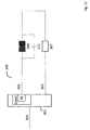
Der Austausch kann beispielsweise dadurch geschehen, dass beispielsweise wie oben beschrieben, mittels eines rückgekoppelten Schieberegisters und eines einfach primitiven Polynoms, das beispielsweise in Form einer entsprechende Logik implementiert ist, eine Zufalls- oder Pseudozufallszahl (ZZ) in einem Zufallsgenerator (ZG) erzeugt wird, die nun aber nicht direkt zur Ansteuerung der Leuchtmittel und/oder der LED, sondern zur Selektion des zu verwendenden aktiven Codes aus der Menge der erlaubten und/oder möglichen Codes für die nächste Sendeperiode aus den Codes der vorgegeben Code-Klasse durch einen Controller (CTR) genutzt wird und diesen zu verwendenden aktiven Code festlegt. Die Code-Klasse entspricht dabei dem gewünschten Füllfaktor. Sie entspricht in der Funktion derjenigen des Tastverhältnisses bei einer PWM. Durch die Selektion der Code-Klasse kann somit ein Füllfaktor für das PCM-Signal festgelegt werden, der von 50% wesentlich abweicht, also zumindest in bestimmten Betriebslagen weniger als 45% und/oder mehr als 55% beträgt. Bei einer entsprechenden Länge der erzeugten Zufallsfolge wird daher das gesamte PCM-Signal, das durch den Controller (CTR) erzeugt wird, zu einem bandbegrenzten aperiodischen Quasizufalls- oder Zufallssignal mit einem Füllfaktor entsprechend der gewählten Code-Klasse, das sich für die Ansteuerung der Leuchtmittel und besonders von LEDs eignet.The exchange can be done, for example, by generating a random or pseudorandom number (ZZ) in a random number generator (ZG), for example as described above, by means of a feedback shift register and a simple primitive polynomial implemented in the form of appropriate logic, for example; but not directly to control the lighting and / or the LED, but to select the active code to be used from the set of allowed and / or possible codes for the next transmission period from the codes of the given code class by a controller (CTR ) and defines this to be used active code. The code class corresponds to the desired fill factor. It corresponds in function to that of the duty cycle in a PWM. By selecting the code class, a filling factor for the PCM signal can be determined that deviates substantially from 50%. So at least in certain operating situations is less than 45% and / or more than 55%. With a corresponding length of the generated random sequence, therefore, the entire PCM signal generated by the controller (CTR) becomes a bandlimited aperiodic quasi-random or random signal with a fill factor corresponding to the selected code class appropriate for the driving of the lighting means and especially of LEDs.
Die Selektion von Codes innerhalb einer Code-Klasse kann aufgrund von EMV-Anforderungen eingeschränkt werden. So ist es, beispielsweise bezogen auf das hier diskutierte Beispiel, denkbar, nicht alle sechs Codes mit Füllfaktor 50% (siehe Tabelle) zu verwenden, sondern beispielsweise nur zwei oder auch nur einen dieser sechs möglichen Codes. Bei der Verwendung von nur einem Code ergäbe sich allerdings ein periodisches Signal, da dann ja keine Auswahl des Codes aufgrund des Zufallssignals mehr stattfinden kann und das PCM-Signal die Eigenschaft eines Zufallssignals verlieren würde.The selection of codes within a code class may be restricted due to EMC requirements. So it is conceivable, for example, based on the example discussed here, not to use all six codes with fill factor 50% (see table), but for example only two or even only one of these six possible codes. Using only one code, however, would result in a periodic signal, since then no selection of the code due to the random signal can take place and the PCM signal would lose the property of a random signal.
Insbesondere bei mittleren Füllfaktoren der PCM-Codes (siehe Tabelle) sind im Übrigen auch sehr hohe Frequenzen möglich. Es besteht daher die Möglichkeit durch die besagte Selektion von bestimmten Codes und durch den Ausschluss von anderen Codes das spektrale Verhalten der PCM-Modulation zu steuern und beispielsweise nur solche Codes als aktive Codes zu erlauben, die vorzugsweise zu niedrigeren Störfrequenzen führen. Somit kann in Abhängigkeit von dem bisher abgestrahlten Spektrum oder dem erwarteten zukünftigen Abstrahlspektrum der nächste aktive Code oder die Menge an zulässigen aktiven Codes bestimmt werden. Auch sollte berücksichtigt werden, dass unter Umständen Codes, die hohe Frequenzanteile besitzen, durch die Ansteuerung, die Zuleitungen und die LEDs selbst aufgrund von deren Tiefpasseigenschaften nicht mehr dargestellt werden können. Insofern ist es sinnvoll, bestimmte kritische Codes entweder nicht darzustellen oder für sehr niedrige Leuchtstärken die Nichtlinearität der LEDs derart zu berücksichtigen, dass durch eine nichtlineare Abbildung der Codes diese auf darstellbare Codes als aktiver Code abgebildet werden. Eine Code-Bit-Folge 0010 könnte so zur Folge 0110 transformiert werden, wobei die erste 1 der Sequenz infolge der Tiefpasseigenschaften des Treibers (DRV, TR1, TR2, TR3), der Zuleitungen (102, 103, 103) und der LEDs (106, 107, 108, R, G, B) nicht dargestellt wird, so dass sich wieder der gewünschte Code 0010 als effektiv durch die LEDs dargestellter aktiver Code ergibt.In particular, at medium filling factors of the PCM codes (see table) are also very high frequencies possible. It is therefore possible by the said selection of certain codes and the exclusion of other codes to control the spectral behavior of the PCM modulation and, for example, to allow only those codes as active codes, which preferably lead to lower interference frequencies. Thus, depending on the spectrum previously emitted or the expected future broadcast spectrum, the next active code or set of allowed active codes can be determined. It should also be considered that under certain circumstances codes that have high frequency components can no longer be represented by the drive, the leads and the LEDs themselves due to their low-pass characteristics. In this respect, it makes sense to either not represent certain critical codes or to take account of the non-linearity of the LEDs for very low luminous powers in such a way that a non-linear mapping of the codes these are mapped to representable codes as active code. A code bit sequence 0010 could thus be transformed to the sequence 0110 in which the first 1 of the sequence is not represented due to the low-pass characteristics of the driver (DRV, TR1, TR2, TR3), the leads (102, 103, 103) and the LEDs (106, 107, 108, R, G, B) so that the desired code 0010 again results as the active code effectively represented by the LEDs.
Eine erfindungsgemäß ansteuerbare Beleuchtungsvorrichtung umfasst daher in einer speziellen Ausprägung typischerweise eine Mehrzahl von Lichtmitteln und/oder LEDs in mindestens zwei, typischerweise jedoch drei oder vier oder mehr verschiedenen Farben. Diese sind typischerweise darauf ausgelegt, an eine elektrische Energieversorgung angeschlossen zu werden. Die Energieversorgung enthält einen elektrischen Stromkreis und eine gemeinsame Potentialreferenz (105). Die Treibermittel (TR1, TR2, TR3, DRV) zum Betreiben der Mehrzahl von Lichtstrahlern und/oder LEDs sind ebenfalls Teil der Vorrichtung. Die Treibermittel (TR1, TR2, TR3, DRV) sind mit den besagten Leuchtmitteln und/oder LEDs und dem Stromkreis verschaltet sowie mit den jeweiligen Strompfaden (102, 103, 104) die zumindest zwei verschiedenfarbigen Leuchtmitteln/LEDs entsprechende Schalter und/oder Regler umfassen. Des Weiteren ist eine Steuerung zum aperiodischen und unabhängigen Öffnen und Schließen der zumindest zwei Schalter oder zumindest zwei Regler vorgesehen. Dabei soll unter dem Öffnen und Schließen im Falle eines besagten Reglers eine Verminderung oder Erhöhung des Energiedurchsatzes durch den jeweiligen Regler zu verstehen sein. Die Steuerung ist dabei an ein drahtgebundenes oder drahtloses Datennetzwerk und/oder eine Datenleitung und/oder einen Daten-Bus angeschlossen. Dabei kann die Steuerung eine von außen mittels Programmierung oder unter Zuhilfenahme eines Adressengenerators, der Teil der Vorrichtung ist, veränderliche Bus-Adresse aufweisen. Diese Bus-Adresse wird durch die Vorrichtung genutzt, um z. B. aus dem Datenstrom Daten, insbesondere Datenpakete oder andere Datenbotschaften, herauszufiltern. Sie identifiziert also den jeweiligen Anteil eines zugewiesenen Eingangsdatenflusses und reagiert darauf typischerweise durch Veränderung eines Parameters der Vorrichtung. Beispielsweise ist es denkbar, einen Code oder Teile der Code-Tabelle (CTAB) oder die ganze Code-Tabelle (CTAB) auszutauschen. An dieser Stelle sei darauf hingewiesen, dass die Größe der Code-Tabelle (CTAB) nicht notwendigerweise 2n betragen muss, wobei n die Länge des Codes bezeichnet. Es ist vielmehr denkbar, dass die Code-Tabelle (CTAB) wesentlich kürzer mit weniger Codes implementiert wird. Es ist also ein wesentliches mögliches Merkmal der Erfindung, dass die Selektion der aktiven Codes durch Vorgaben über die besagte Datenschnittstelle beeinflusst wird. Dabei sind typischerweise zumindest zwei der besagten Leuchtmittel LEDs. Die Steuerung (101) erzeugt typischerweise mittels der Treiber (TR1, TR2, TR3) eine Mehrzahl von PCM-Signalen (102, 103, 104). Vorzugsweise korrelieren die PCM-Signale (102, 103, 104) nicht miteinander. Diese Nicht-Korrelation kann sich auch nur auf Abschnitte der Signale beziehen. Es ist beispielsweise denkbar, dass eine Korrelation erst nach 256 oder 512 oder 1024 oder 2048 oder 4096 Takten auftritt, was aber nicht dem technischen Optimum entspricht. Die Nicht-Korellation ist aber nicht zwingend erforderlich. Jedes der PCM-Signale (102, 103, 104) korrespondiert dabei jeweils mit einer Farbe der Mehrzahl von LEDs (106, 107, 108, R, G, B) und/oder Leuchtmitteln verschiedener Farben. Dabei wird jedes der PCM-Signale (102, 103, 104) erzeugt, indem jeweils mindestens ein entsprechender, dem jeweiligen PCM-Signal zugeordneter Schalter oder Regler zum Öffnen und Schließen entsprechend dem jeweiligen logischen Zustand des ebenfalls dem jeweiligen PCM-Signal zugehörigen internen PCM-Signals (PCM-S) des jeweiligen Kanals (CHN) der Steuereinheit (101) veranlasst wird. Dabei ist das Frequenzspektrum des Betrags der Frequenz des PCM-Signals, wie oben beschrieben, bandbegrenzt. Das bedeutet, dass das Signal eine untere Grenzfrequenz ωu und/oder eine obere Grenzfrequenz ωo besitzt.A lighting device which can be controlled according to the invention therefore typically comprises a plurality of light means and / or LEDs in at least two, but typically three or four or more different colors, in a specific embodiment. These are typically designed to be connected to an electrical power supply. The power supply includes an electrical circuit and a common potential reference (105). The driver means (TR1, TR2, TR3, DRV) for operating the plurality of light emitters and / or LEDs are also part of the device. The driver means (TR1, TR2, TR3, DRV) are connected to the said light sources and / or LEDs and the circuit, and the respective current paths (102, 103, 104) comprise the switches and / or regulators corresponding to at least two differently colored light sources / LEDs , Furthermore, a control for the aperiodic and independent opening and closing of the at least two switches or at least two regulators is provided. In this case, under the opening and closing in the case of a said regulator, a reduction or increase in the energy throughput by the respective controller should be understood. The controller is connected to a wired or wireless data network and / or a data line and / or a data bus. In this case, the controller may have a variable from the outside by means of programming or with the aid of an address generator, which is part of the device variable bus address. This bus address is used by the device to z. B. from the data stream data, in particular data packets or other data messages, filter out. It thus identifies the respective proportion of an assigned input data flow and reacts thereto typically by changing a parameter of the device. For example, it is conceivable to use a code or parts of Code table (CTAB) or the whole code table (CTAB). It should be noted that the size of the code table (CTAB) does not necessarily have to be 2 n , where n denotes the length of the code. It is rather conceivable that the code table (CTAB) is implemented much shorter with fewer codes. It is thus an essential possible feature of the invention that the selection of the active codes is influenced by specifications via the said data interface. At the same time, typically at least two of the luminous means are LEDs. The controller (101) typically generates a plurality of PCM signals (102, 103, 104) by means of the drivers (TR1, TR2, TR3). Preferably, the PCM signals (102, 103, 104) do not correlate with each other. This non-correlation may also refer only to portions of the signals. For example, it is conceivable that a correlation only occurs after 256 or 512 or 1024 or 2048 or 4096 clocks, which does not correspond to the technical optimum. Non-corellation is not mandatory. Each of the PCM signals (102, 103, 104) corresponds in each case to one color of the plurality of LEDs (106, 107, 108, R, G, B) and / or light sources of different colors. In this case, each of the PCM signals (102, 103, 104) is generated by in each case at least one corresponding switch or controller associated with the respective PCM signal for opening and closing in accordance with the respective logic state of the internal PCM also associated with the respective PCM signal Signal (PCM-S) of the respective channel (CHN) of the control unit (101) is caused. Here, the frequency spectrum of the magnitude of the frequency of the PCM signal is band limited as described above. This means that the signal has a lower limit frequency ω u and / or an upper limit frequency ω o .
In einer besonderen Ausprägung der Erfindung bestimmt der besagte Datenflussanteil, also typischerweise ein Datenpaket, die Daten zur Bestimmung der jeweiligen aktiven Bereiche der Sende-Codes, die die zumindest zwei verschiedenfarbigen LEDs aussenden. Besonders vorteilhaft ist es, wenn der Datenflussanteil, also typischerweise ein für die Vorrichtung bestimmtes Datenpaket, eine vordefinierte oder vorprogrammierte Farbpalette in Form einer Untermenge der möglichen aktiven Codes bestimmt. Die Vorrichtung verfügt daher je Leuchtmittel über eine Teilvorrichtung, die die diesem Datenflussanteil entsprechende Untermenge der möglichen aktiven Codes in eine Zufallssequenz von Ein- und Ausschaltsignalen und insbesondere in ein PCM-Signal (PCM-S) für die besagten Schalter mit dem vorgewählten Füllfaktor umwandelt.In a particular embodiment of the invention, said data flow component, that is to say typically a data packet, determines the data for determining the respective active regions of the transmission codes which emit the at least two differently colored LEDs. It is particularly advantageous if the data flow component, that is to say typically a data packet intended for the device, determines a predefined or preprogrammed color palette in the form of a subset of the possible active codes. The device therefore has, per light source, a subdevice which converts the subset of the possible active codes corresponding to this data flow component into a random sequence of on and off signals and in particular into a PCM signal (PCM-S) for the said switch with the preselected fill factor.
In einer weiteren Ausprägung der Erfindung umfasst die Steuerung zumindest zwei Register für die Ansteuerung der zumindest zwei verschiedenfarbigen Leuchtmittel/LEDs. Statt zweier Register können selbstverständlich auch Teile von Registern verwendet werden. Diese Register bzw. Registerteile werden jeweils zum Speichern von Werten verwendet, die zum Beispiel die besagte Datenschnittstelle aus einem Datenfluss erhält. Diese Datenflussanteile, insbesondere Datenpakete, werden dann den jeweiligen verschiedenfarbigen Leuchtmitteln/LEDs zugeordnet und geben beispielsweise jeweils den besagten Füllfaktor und damit die aktive Code-Klasse vor. Dies kann zum einen in direkter Weise geschehen in der Form, dass der Inhalt des Datenflussanteils direkt den Füllfaktor widerspiegelt, der verwendet werden soll oder zum anderen in der Weise geschehen, dass der Inhalt des Datenflussanteils auf den Füllfaktor direkt oder indirekt über weitere Tabellen verweist, die verwendet werden sollen. Beispielsweise ist die Verwendung von Farbpaletten denkbar, auf die dann der Registerinhalt verweisen kann. Dies ist besonders effizient, wenn z. B. eine Beschränkung auf 16 Farben stattfindet. In diesem Fall müssen nicht alle Daten, sondern beispielsweise nur ein 4-Bit-Datenwort für die Farbe übertragen werden.In a further embodiment of the invention, the controller comprises at least two registers for controlling the at least two differently colored lamps / LEDs. Of course, parts of registers can be used instead of two registers. These registers or register parts are each used to store values which, for example, receives the said data interface from a data flow. These data flow components, in particular data packets, are then assigned to the respective differently colored lamps / LEDs and, for example, each specify the said fill factor and thus the active code class. This can happen on the one hand in the form that the content of the data flow component directly reflects the fill factor that is to be used or, on the other hand, the contents of the data flow component directly or indirectly refer to the fill factor via further tables, which should be used. For example, the use of color palettes is conceivable, which can then refer to the register contents. This is particularly efficient when z. B. a restriction to 16 colors takes place. In this case, not all data, but for example, only a 4-bit data word for the color must be transmitted.
Mit Hilfe dieses beispielhaften 4-Bit-Datenwortes wird dann der Füllfaktor jedes einzelnen PCM-Signals (102, 103, 104, PCM-Out) mit Hilfe der Farbpalette bestimmt.With the aid of this exemplary 4-bit data word, the fill factor of each individual PCM signal (102, 103, 104, PCM-Out) is then determined using the color palette.
Die Erfindung kann zweckmäßigerweise über eine Steuerung verfügen, die dafür eingerichtet ist, den Code-Füllfaktor geeignet einzustellen. Dabei wird wie oben beschrieben festgelegt, welche Art von Codes überhaupt verwendet werden dürfen. In dem hier dargestellten Beispiel eines vier Bit-Codes ergeben sich die möglichen Füllfaktoren von 0%, 25%, 50%, 75% und 100% der beispielhaften Code-Klassen 0 bis 4. Wie der Tabelle oben zu entnehmen ist, sind für die Füllfaktoren nahe dem Wert von 50% jeweils die maximale Anzahl an Code-Variationen möglich. Wird dieser Code an ein Leuchtmittel bzw. eine LED gesendet, so ist die mittlere Einschaltdauer pro Einschaltzyklus gleich dem Produkt aus Code-Transmissionsdauer und Füllfaktor. Das bedeutet, dass das Verhalten demjenigen einer PWM analog ist, bei der die Datenwerte zum Bestimmen der mittleren Einschaltdauer pro Zeiteinheit der zugehörigen Farb-LEDs (allg. Farb-Leuchtmittel) zugeordnet werden.The invention may conveniently have a controller adapted to adjust the code fill factor appropriately. It will be like described above, which type of code may be used at all. In the example of a four-bit code shown here, the possible filling factors of 0%, 25%, 50%, 75% and 100% of the exemplary code classes 0 to 4 result Filling factors close to the value of 50% each, the maximum number of code variations possible. If this code is sent to a light source or an LED, then the average duty cycle per duty cycle is equal to the product of code transmission time and fill factor. This means that the behavior is analogous to that of a PWM in which the data values for determining the average duty cycle per time unit are assigned to the associated color LEDs (general color lamps).
In einer weiteren Ausprägung der Erfindung umfasst die Steuerung zumindest ein weiteres Register für die Ansteuerung der zumindest zwei verschiedenfarbigen Leuchtmitteln bzw. LEDs. Statt dieses zusätzlichen dritten Registers können selbstverständlich auch Teile von Registern verwendet werden. Dieses dritte Register bzw. dieser dritte Registerteil wird jeweils zum Speichern eines dritten Wertes verwendet, den zum Beispiel die besagte Datenschnittstelle ebenfalls aus einem Datenfluss erhält. Auch hier ist wieder die direkte Verwendung des Wertes möglich, aber auch die indirekte Verwendung über eine der Farbpalette ggf. zugeordnete Code-Palette. In dem letzteren Fall verweist der Inhalt des dritten Wertes beispielsweise auf die richtige Code-Tabelle. Dieser Datenflussanteil, insbesondere ein Datenpaket, wird bei der direkten Verwendung der aktiven Code-Tabelle zugeordnet und steuert beispielsweise die Selektion der Codes aus der Code-Tabelle.In a further embodiment of the invention, the controller comprises at least one further register for the control of the at least two differently colored lamps or LEDs. Of course, parts of registers can be used instead of this additional third register. This third register or this third register part is used in each case for storing a third value, which, for example, the said data interface also receives from a data flow. Again, the direct use of the value is possible, but also the indirect use of a color palette possibly associated with the code palette. For example, in the latter case, the content of the third value refers to the correct code table. This data flow component, in particular a data packet, is allocated when the active code table is used directly and controls, for example, the selection of the codes from the code table.
Dabei ist es grundsätzlich sinnvoll, die Vorrichtung mit einem Gehäuse zu versehen, das im Wesentlichen die Mehrzahl von Leuchtmitteln bzw. LEDs, die Treibermittel (TR1, TR2, TR3, DRV) und die besagte Steuerung (101) umgibt.It is basically useful to provide the device with a housing which essentially surrounds the plurality of light sources or LEDs, the driver means (TR1, TR2, TR3, DRV) and the said controller (101).
In einer weiteren Ausprägung der Erfindung umfasst diese einen elektrischen Regler zum Steuern der über die Strompfade zu der Mehrzahl von LEDs gelieferten Maximalströme, um so die Maximalströme auf konstanten Maximalwerten zu halten. Dies hat den Vorteil, dass die Farbtemperatur der LEDs konstant gehalten werden kann.In a further embodiment of the invention, this includes an electrical regulator for controlling the supplied via the current paths to the plurality of LEDs Maximum currents so as to keep the maximum currents at constant maximum values. This has the advantage that the color temperature of the LEDs can be kept constant.
Es wird also zusätzlich zur Vorgabe des PCM-Pulsmusters typischer Weise auch die Amplitude des PCM-Pulssignals geregelt.Thus, in addition to the specification of the PCM pulse pattern, the amplitude of the PCM pulse signal is also typically controlled.
Darüber hinaus kann die Erfindung einen Farbsensor vorsehen, der es der Steuereinheit (101) ermöglicht, den Füllfaktor und/oder die Farbtemperatur der Leuchtmittel bzw. LEDs so nachzuregeln, das die erwünschte Farbabstrahlung oder Farbreflektion des bestrahlten Objekts erzielt wird.In addition, the invention can provide a color sensor that allows the control unit (101) to adjust the fill factor and / or the color temperature of the lamps or LEDs so that the desired color emission or color reflection of the irradiated object is achieved.
So ist es beispielsweise sinnvoll, die Farbtemperatur eines Kanals (CHN, CHN1, CHN2, CHN3) immer dann zu messen, wenn die anderen Kanäle ausgeschaltet sind, was bei nicht korrelierten PCM-Signalen (102, 103, 104, PCM-Out), die auf Zufallssignalen oder Pseudozufallszahlen beruhen, immer wieder der Fall sein wird. Dies ermöglicht es, durch Nachregelung des Maximalstroms und/oder der Maximalspannung und/oder der Maximalenergie die Farbtemperatur sehr einfach nachzuregeln.For example, it makes sense to measure the color temperature of one channel (CHN, CHN1, CHN2, CHN3) whenever the other channels are off, which is not the case with uncorrelated PCM signals (102, 103, 104, PCM-Out). which are based on random or pseudo-random numbers, will always be the case. This makes it possible to readjust the color temperature very easily by readjusting the maximum current and / or the maximum voltage and / or the maximum energy.
In einer weiteren beispielhaften Ausprägung der Erfindung umfasst diese einen elektrischen Regler zum Steuern der über die Strompfade zu der Mehrzahl von Leuchtmitteln bzw. LEDs gelieferten Maximalenergie, um so die durch die Leuchtmittel bzw. LEDs aufgenommene Maximalenergie auf konstanten Maximalwerten zu halten. Eine solche Regelung hat im Gegensatz zur Regelung des Stromes den Vorteil, dass die Energiemenge, die umgesetzt wird unter Kontrolle gehalten werden kann.In a further exemplary embodiment of the invention, the latter comprises an electrical regulator for controlling the maximum energy supplied via the current paths to the plurality of light-emitting means or LEDs so as to keep the maximum energy absorbed by the light-emitting means or LEDs at constant maximum values. Such a regulation has the advantage, in contrast to the regulation of the current, that the amount of energy that is converted can be kept under control.
In einer weiteren zweckmäßigen Ausprägung der Erfindung umfasst diese einen Regler zum Steuern der über die Strompfade zu der Mehrzahl von LEDs gelieferten Maximalströme oder der elektrischen Maximalenergie, um so die Maximalströme und/oder Maximalenergie auf konstanten Maximalwerten zu halten, wobei das Gehäuse im Wesentlichen zusätzlich zur Mehrzahl von LEDs, den Treibermitteln (TR1, TR2, TR3, DRV) und der Steuerung (101) nun auch den Regler (PWR) umgibt. Eine solche integrierte Lösung hat den Vorteil, dass die EMV Robustheit weiter erhöht wird.In a further expedient embodiment of the invention, the latter comprises a regulator for controlling the maximum currents or the maximum electrical energy supplied via the current paths to the plurality of LEDs, in order thus to increase the maximum currents and / or maximum energy to constant maximum values The housing now essentially surrounds the controller (PWR) in addition to the plurality of LEDs, the driver means (TR1, TR2, TR3, DRV) and the controller (101). Such an integrated solution has the advantage that the EMC robustness is further increased.
In einer weiteren vorzugsweisen Ausprägung der Erfindung ist die Steuerung zum Identifizieren und Reagieren auf einen Eingangsdatenflussanteil, also dem jeweiligen Datenpaket, in Übereinstimmung mit einem LIN-Datenprotokoll und/oder einem Flexray-Datenprotokoll und/oder einem CAN-Datenprotokoll und/oder einem KNX-Datenprotokoll und/oder einem IP-Datenprotokoll und/oder einem USB-Datenprotokoll und/oder einem HDMI-Datenprotokoll eingerichtet. Dabei ist es von besonderer Bedeutung, wenn die Einrichtung selbstständig ihre Position im Netzwerk feststellen kann. Ganz besonders vorteilhaft ist es, wenn eine erste Datenschnittstelle und eine zweite Datenschnittstelle zur Verfügung stehen. Die Durchleitung von der ersten Datenschnittstelle zur zweiten Datenschnittstelle sollte dabei vorzugsweise davon abhängen, ob die Datenschnittstelle bereits eine gültige Bus-Adresse erhalten hat. Sofern dies nicht der Fall ist, werden die Datenpakete nicht weitergeleitet.In a further preferred embodiment of the invention, the controller for identifying and responding to an input data flow component, ie the respective data packet, in accordance with a LIN data protocol and / or a Flexray data protocol and / or a CAN data protocol and / or a KNX Data protocol and / or an IP data protocol and / or a USB data protocol and / or an HDMI data protocol. It is of particular importance if the institution can independently determine its position in the network. It is particularly advantageous if a first data interface and a second data interface are available. The transmission from the first data interface to the second data interface should preferably depend on whether the data interface has already received a valid bus address. If this is not the case, the data packets are not forwarded.
Dementsprechend ist es auch sinnvoll, wenn die Erfindung eine Funkschnittstelle und/oder eine Bluetooth Schnittstelle und/oder eine WLAN Schnittstelle nutzt.Accordingly, it also makes sense if the invention uses a radio interface and / or a Bluetooth interface and / or a WLAN interface.
In einer weiteren Ausprägung der Erfindung umfasst jeder Eingangsdatenflussanteil vorteilhafterweise jeweils ein Datenwort aus einem oder einer Mehrzahl von Bits oder Bytes für jede Leuchtmittel- bzw. LED-Farbe. Dabei enthält das Byte 8 Datenbits zum Festlegen der Intensität der jeweiligen LED-Farbe innerhalb eines Bereichs, der den Dezimalzahlen 0 bis 255 entspricht. Die Steuerung ist dabei dafür eingerichtet, den Füllfaktor der jeweils angewandten Codes in Übereinstimmung mit dem Bitinhalt des jeweiligen Datenwortes zu steuern.In a further embodiment of the invention, each input data flow component advantageously comprises in each case one data word of one or a plurality of bits or bytes for each luminous means or LED color. The byte contains 8 data bits for setting the intensity of the respective LED color within a range corresponding to the decimal numbers 0 to 255. The controller is set up to control the filling factor of the respectively applied codes in accordance with the bit content of the respective data word.
In einer weiteren Ausprägung der Erfindung umfasst ein Verbraucher eine Mehrzahl von roten und/oder grünen und/oder blauen und/oder gelben und/oder weißen Leuchtmitteln bzw. LEDs und/oder UV-Leuchtmitteln bzw.-LEDs und/oder IR-Leuchtmitteln bzw. -LEDs.In a further embodiment of the invention, a consumer comprises a plurality of red and / or green and / or blue and / or yellow and / or white bulbs or LEDs and / or UV bulbs or LEDs and / or IR bulbs or LEDs.
Dabei kann grundsätzlich die Mehrzahl von Leuchtmitteln bzw. LEDs eine serielle und/oder parallele Anordnung von Leuchtmitteln bzw. LEDs umfassen.In principle, the plurality of light sources or LEDs may comprise a serial and / or parallel arrangement of light sources or LEDs.
Eine solche Vorrichtung kann in einem Beleuchtungsnetzwerk eingesetzt werden. Ein solches Beleuchtungsnetzwerk umfasst eine zentrale Steuerung zum Erzeugen des besagten Eingangsdatenflusses und eine Mehrzahl von Beleuchtungsvorrichtungen wie zuvor beschrieben. Dabei sollte jeder der Beleuchtungsvorrichtungen dafür eingerichtet sein, den Datenfluss zu empfangen und seine veränderliche Bus-Adresse während der Initialisierungsphase anders als die übrigen Beleuchtungsvorrichtungen des Beleuchtungsnetzwerks und im Gegensatz zum Stand der Technik selbst zu setzen, um sicherzustellen, dass die Beleuchtungseinrichtungen auf verschiedene Anteile des Eingangsdatenflusses reagieren. Es ist daher von besonderem Vorteil, wenn jede der Beleuchtungsvorrichtungen über eine Einrichtung verfügt, um eine veränderliche Netzwerkadresse (Bus-Adresse) selbst zu erzeugen, die vorzugsweise von der Position im Beleuchtungsnetzwerk abhängt. Beispielhafte Verfahren hierzu sind in
Bei einer solchen Art der Autoadressierung erfolgt insbesondere keine Zuweisung einer Bus-Adresse an einen vorbestimmten Endknoten durch die Steuerung. Vielmehr stellt die Steuerung beispielsweise eine Bus-Adresse allen Bus-Teilnehmern (Beleuchtungsvorrichtung) geleichzeitig zur Verfügung und die Bus-Teilnehmer entscheiden, ob diese Bus-Adresse für den jeweiligen Bus-Teilnehmer geeignet ist. Wenn diese Entscheidung positiv ausfällt, übernimmt der Bus-Teilnehmer die zur Verfügung gestellte Bus-Adresse und signalisiert allen anderen Bus-Teilnehmern, dass diese Bus-Adresse übernommen wurde bzw. dass nun die Übernahme der nächsten Bus-Adresse durch einen anderen Bus-Teilnehmer erfolgen soll. Diese Signalisierung kann beispielsweise durch die Durchleitung des Datenflusses von der besagten ersten Datenschnittstelle der Beleuchtungsvorrichtung zur besagten zweiten Datenschnittstelle der Beleuchtungsvorrichtung und umgekehrt ab dem Zeitpunkt erfolgen, ab dem die veränderliche Bus-Adresse der Beleuchtungsvorrichtung übernommen wurde.In particular, in such a type of auto-addressing, no assignment of a bus address to a predetermined end node is made by the controller. Rather, the control provides, for example, a bus address to all bus subscribers (lighting device) at the same time and the bus subscribers decide whether this bus address is suitable for the respective bus subscriber. If this decision is positive, the bus user accepts the provided bus address and signals to all other bus users that this bus address has been accepted or that now the assumption of the next bus address should be made by another bus participant. This signaling can take place, for example, by passing the data flow from said first data interface of the lighting device to said second data interface of the lighting device and vice versa from the time at which the variable bus address of the lighting device has been adopted.
Bei den oben zitierten Autoadressierungsverfahren wird die Bus-Adresse also nicht einem Bus-Teilnehmer konkret zugewiesen. Es ist somit so, dass die Steuerung dem Netzwerk - also allen Bus-Teilnehmern - eine Bus-Adresse zur (freien) Verfügung stellt. Einzelne Bus-Teilnehmer entscheiden dabei entsprechend diesem Verfahren selbstständig, ob sie diese Bus-Adresse verwenden. Es handelt sich somit nicht um eine Zuweisung bezogen auf einen einzelnen Bus-Teilnehmer, sondern um die Zuweisung der Bus-Adresse zu einer Netzwerk-Position. Der besondere Vorteil dieses Verfahrens liegt darin, dass die einzelnen Bus-Teilnehmer aufgrund ihrer Position ihre Bus-Adresse erhalten und nicht vorkonfiguriert werden müssen.In the auto-addressing method cited above, therefore, the bus address is not concretely assigned to a bus subscriber. It is thus the case that the controller provides the network - ie all bus users - with a bus address for (free) use. Individual bus participants decide independently according to this procedure whether they use this bus address. It is thus not an assignment with respect to a single bus participant, but the assignment of the bus address to a network position. The particular advantage of this method is that the individual bus users receive their bus address due to their position and do not have to be preconfigured.
Hierfür kann es auch sinnvoll sein, dass der Bus-Teilnehmer die Adresstabelle aller verwendeten Netzwerkadressen (Bus-Adressen) des Beleuchtungsnetzwerks vorhält. Der Bus-Teilnehmer wählt selbstständig, bestimmt durch die Position im Kabelbaum, eine der Bus-Adressen aus.For this purpose, it may also be appropriate for the bus user to maintain the address table of all network addresses (bus addresses) of the lighting network used. The bus user selects one of the bus addresses independently, determined by the position in the cable harness.
Im Folgenden wird die Erfindung anhand der Zeichnungen weiter erläutert.
- Fig. 1
- zeigt das Spektrum einer bipolaren PWM entsprechend dem Stand der Technik.
- Fig. 2
- zeigt den schematischen Aufbau einer erfindungsgemäß ansteuerbaren beispielhaften Vorrichtung 100 mit drei Gruppen von RGB-
Leuchtmitteln Die Steuereinheit 101 verfügt in diesem Beispiel über eineDatenschnittstelle 109.Über diese Datenschnittstelle 109 kommuniziert dieVorrichtung 100 mit dem Beleuchtungsnetzwerk, indie die Vorrichtung 100 eingebunden ist.Die Steuereinheit 101 gibt drei PCM-Signale Leuchtmitteln Signal 102 derrot strahlenden Leuchtmittelgruppe 108 zugeordnet, das zweite PCM-Signal 103 der blau strahlenden Leuchmittelgruppe 107 zugeordnet und das dritte PCM-Signal 104 der grün strahlenden Leuchtmittelgruppe 106 zugeordnet.Alle Komponenten über ein Bezugspotenzial 105 verbunden. In einem Kfz ist dieses Bezugspotenzial vorzugsweise mit der Karosserie verbunden. - Fig. 3
- zeigt einen beispielhaften Basis-
Systemtakt 1 der die Position der Flanken des PCM-Steuersignals 4 bestimmt. Die Zeit ist dabei von links nach rechts dargestellt. In dem Beispiel sind dieCodes 2, die jeweils aktiv sind, dargestellt. Die möglichen beispielhaften Codes mit beispielhafter Code-Länge vier sind in der Tabelle oben aufgelistet. Es handelt sich um die bereits dargestellten beispielhaften 4-Bit-Codes. In der Realität sind, wie erwähnt, andere und insbesondere größere Code-Längen sinnvoll. Da die Codes eine Code-Länge von vier Bit haben, wird mit jedem vierten Takt des Basis-Systemtakts 1 erst eine neue Zufallszahl 5 bestimmt und dann der entsprechende Code als neuer aktiverCode 2 gewählt. Dabei wird das Verfahren zur Bestimmung der Zufallszahl ZZ vorzugsweise so gewählt, dass alle Codes des gerade aktiven Füllfaktors mit der gleichen Wahr-scheinlichkeit gewählt werden können. In dem Beispiel beträgt der aktive Füllfaktor 50%.
Zum Vergleich zu einer PWM-Modulation mit einem Duty-Cycle von 50 % ist ganz unten inFig. 3 das entsprechende PWM-Signal 6 dargestellt, was deutlich den Unterschied der erfindungsgemäßen PCM-zur bekannten PWM-Modulation und - Ansteuerung der Leuchtmittel bzw. LEDS zeigt.
Der Basis-Systemtakt 1 könnte, statt monofrequent, wie inFig. 3 gezeigt, auch innerhalb vorgebbarer Frequenzgrenzen (mit der unteren Grenze ungleich Null) bandbreitenbegrenzt sein, was zu einer asynchronen Taktung des Systems führen würde. - Fig. 4
- zeigt eine beispielhafte
Implementation der Steuereinheit 101. Die beispielhafte Steuereinheit verfügt über einen Mikro-Controller µC, der zusammen mit einer Speichereinheit RAM/ROM/FLASH und dem Taktgenerator CLK ein Mikrorechnersystem bildet. Die Teilvorrichtungen des beispielhaften Mikrorechnersystems sind über einen internen Daten- und Steuerbus IBUS miteinander verbunden. An diesen internen Daten- und Steuerbus IBUS ist eine Datenschnittstelle IF angeschlossen, über die der Mikro-Controller µC mit dem Rest des Beleuchtungsnetzwerks kommunizieren kann. Die Datenschnittstelle IF ist dabei mit dem externen Bus EBUS verbunden, der zusammen mit der zuvor genannten Datenschnittstelle (IF) mit der zuvor erwähnten externen Datenschnittstelle (109) derFig. 2 identisch ist. Eine Energieversorgung PWR versorgt die Vorrichtung mit Energie. Die Energieversorgung PWR erhält die elektrische Energie über einen externen Energieanschluss EXTPWR. Es ist vorteilhaft, wenn der Mikro-Controller µC deren Zustand über den internen Bus IBUS abfragen und dadurch ggf. die Leistung der Vorrichtung verändern kann. Eine Schaltung zur Detektion des Einschaltvorgangs PWRst setzt die Vorrichtung in einen definierten Zustand zurück, wenn die externe Energieversorgung der Vorrichtung über den externen Energieanschluss EXTPWR eingeschaltet wird. Zu diesem Zeitpunkt versucht eine Adresserzeugung AdrGen eine im Beleuchtungsnetzwerk nur einmal vergebene Bus-Adresse zu erzeugen. Diese wird der Schnittstelle IF zur Verfügung gestellt. Dieses Basis-Rechnersystem entspricht dabei weitestgehend dem Stand der Technik.
Die Vorrichtung verfügt nun je PCM-Kanal CHN, CHN1, CHN2, CHN3 über eine PCM-Treibereinrichtung DRV, TR1, TR2, TR3 mit einem Ausgangssignal PCM-Out, die je eines der besagten PCM-Signale Leuchtmitteln Fig. 4 erzeugt mit Hilfe der Zeitbasis CLK ein Zufallsgenerator ZG eine Zufallszahl ZZ und stellt diese einem Controller CTR zur Verfügung. Der Controller erzeugt mit Hilfe der Zeitbasis CLK, der Code-Tabelle CTAB und eines Registerwertes REG, der den Füllfaktor festlegt, das PCM-Steuersignal PCM-S. Dieses wird durch einen Treiber DRV zu dem besagten nieder-ohmigen Ausgangsignal PCM-Out umgesetzt. Der Treiber kann dabei einen Regler enthalten, der den Maximalpegel des PCM-Out-Signals entsprechend einer Vorgabe regelt. Diese Vorgabe kann insbesondere von extern, beispielsweise über ein Register oder durch Messung der Farbtemperatur, erfolgen. Der Regler kann dabei den Maximalstrom oder die Maximalenergie oder die Maximalspannung ausregeln. Eine Regelung des Maximalstroms ist besonders vorteilhaft. Der Regler ist in diesem Sinne ein Teil des Treibers. Der Treiber verfügt in der Regel über mindestens einen ersten Schalter, der in Abhängigkeit vom PCM-Steuersignal PCM-S den Treiberausgang PCM-Out mit der Energiequelle, bevorzugt über den Regler, verbindet. In vielen Realisierungen wird der Treiber über eine Push-Pull-Stufe mit zwei Schaltern verfügen, von denen der zusätzlich zweite Schalter den Ausgang PCM-Out nur dann beispielsweisemit dem Bezugspotenzial 105 verbindet, wenn der andere zuvor erwähnte erste Schalter geöffnet ist. Als Schalter werden typischer Weise Bipolar- oder Feldeffekt-Transistoren oder ähnliches verwendet. Es ist dabei besonders vorteilhaft, wenn die Komponenten ihren Status an den Mikro-Controller µC melden können und von diesem konfiguriert werden können. Der Treiber DRV wird dabei durch die Spannungsversorgung PWR mit Energie versorgt. Dabeiwird das Referenzpotenzial 105 über einen separaten Anschluss Ref zugeführt. Über diesen Anschluss wird der Strom der Treiber TR1, TR2, TR3, DRV von den RGB-Leuchtmitteln Fig. 2 sind drei Kanäle CHN notwendig. In derFig. 4 ist zur Vereinfachung jedoch nur ein Kanal CHN als Repräsentant für die Mehrzahl an Kanälen CHN1, CHN2,CHN3 einer Steuereinrichtung 101 eingezeichnet. Die besagten PCM-Signale Fig. 2 werden jeweils an einen Ausgang PCM-Out je eines Kanals CHN1, CHN2,CHN3 der Steuereinrichtung 101 angeschlossen. Da es sich nur um ein Beispiel handelt, wird bei den PCM-Signalen in der Folge immer auch ein Signal PCM-Out für einen einzelnen Kanal vermerkt. Dieses Signal PCM-Out repräsentiert jedoch bei der Verwendung mehrerer Kanäle CHN1, CHN1, CHN3 mehrere PCM-Signale Signale - Fig. 5
- zeigt ein beispielhaftes Beleuchtungsnetzwerk mit einer zentralen Kontrolleinheit CENTR und vier beispielhaften Vorrichtungen 100, die über einen sternförmigen Bus miteinander verbunden sind.
- Fig. 6
- zeigt ein beispielhaftes Beleuchtungsnetzwerk mit einer zentralen Kontrolleinheit CENTR und vier beispielhaften Vorrichtungen 100, die über einen sequentiellen Bus miteinander verbunden sind. Dabei verfügt jede der Vorrichtungen über eine weitere zweite Datenschnittstelle. Dies ermöglicht die Durchführung eines Verfahrens zur Ermittlung der veränderlichen Bus-Adresse wie in
DE-B-102 56 631 EP-B-1 490 772 EP-B-1 364 288 EP-A-2 571 200 - Fig. 7
- zeigt eine beispielhafte schematische Vorrichtung mit zwei Schnittstellen IF1, IF2, die jeweils an einen Datenbus EBUS1, EBUS2 angeschlossen sind. Diese Vorrichtung ist für ein Bussystem entsprechend
Fig. 6 geeignet. Die Vorrichtung verfügt darüber hinaus beispielhaft über eine Funkschnittstelle TX/RX. - Fig. 8
- zeigt eine beispielhafte schematische Vorrichtung 200 mit zu einem Stern
verschalteten induktiven Lasten jeweils ein Steuersignal EP-A-2 688 209 Sternpunkt als Potenzialreferenz 205. DieSteuerung der Steuereinrichtung 201 erfolgt wieder über einen Datenbus. Solche Konstruktionen werden vorzugsweise für die Erzeugung von Drehfeldern verwendet. - Fig. 9
- zeigt eine Vorrichtung ähnlich der aus
Fig. 8 mit dem Unterschied, dassnun der Sternpunkt 205 über einen weiteren Kanal CHN4 und einen zugehörigen Treiber TR angesteuert wird. Der Ausgang desTreibers 210 Treibt dabei eine separate Sternpunktsinduktivität. 211 Ziel ist es dabei typischerweise, dass die Sternpunktsspannung 0V wird. Eine solche Topologie ist beispielsweise sinnvoll, wenn die Informationen der Messmittel der Kanäle CHN1, CHN2, CHN3, CHN4 auch zur Lagebestimmung des Rotors einer rotierenden Maschine, beispielsweise eines bürstenlosen Gleichstrommotors, herangezogen werden sollen. - Fig. 10
- zeigt eine Vorrichtung ähnlich der aus
Fig. 9 mit dem Unterschied, dass dasBezugspotenzial der Steuereinrichtung 201 nicht mehr mit dem Sternpunkt verbunden ist. - Fig. 11
- zeigt eine Vorrichtung ähnlich der in
Fig. 8 mit dem Unterschied, dass die Induktivitäten nun im Dreieck geschaltet sind. - Fig. 12
- zeigt eine andere einschlägige Anwendung, an der sich besonders gut die Möglichkeiten zur Verbesserung der elektromagnetischen Verträglichkeit diskutieren lassen. Die Vorrichtung verfügt beispielhaft hier nur über einen einzigen Kanal CHN1. Dieser steuert über den Treiber
TR die Leitung 302. Die Leitung weist eine parasitäre Induktivität 308 und eine parasitäre Kapazität 312 auf. Es sei dieAufgabe der Schaltung 300,einen Verbraucher 307, also beispielsweise eine LED, mit elektrischer Energie in der Art zu versorgen, dass durch die Schaltvorgänge der Schwingkreis aus Induktivität 308 undKapazität 307 nicht anschwingt oder, wenn dies doch geschehen solle, schnell ausschwingt.
Das Problem beschränkt sich dabei nicht nur auf die Resonanzfrequenz des Schwingkreises bestehend aus Induktivität 308 undKapazität 312, sondern erstreckt sich typischerweise auch auf Oberwellen der Resonanzfrequenz.
Typischerweise lässt sich beispielsweise ein Empfindlichkeitsspektrum e(f) in Abhängigkeit von der Frequenz angeben. Diese soll nun durch dieVorrichtung 200 und dieSteuereinrichtung 201 berücksichtigt werden. Diese Berücksichtigung erfolgt durch geeignete Auswahl des nächsten zu sendenden Codes durch dieSteuereinrichtung 201. Hierzu speichert die Steuereinheit zumindest eine zeitbegrenzte Sequenz der gesendeten Codes und damit die gesendete Bit-Sequenz ab. Vor der Aussendung eines Codes wird dieser durch dieSteuereinrichtung 201 auf Eignung geprüft. Es wird der geeignetste Code gesendet. Diese Eignungsprüfung, also eine Bewertung, erfolgt beispielsweise so, dass die abgespeicherte Code-Sequenz um den zu bewertenden Code ergänzt wird und die so erhaltene Code-Sequenz Fourier-transformiert wird. Hierbei ist übrigens zu beachten, dass die Länge der so erhaltenen Code-Sequenz nicht schon selbst Transienten erzeugt, die mit der Resonanzfrequenz und oder deren Oberwellenfrequenzen korrelieren. Nun wird das durch die Fourier-Transformation erhaltene Spektrum der ergänzten Code-Sequenz mit dem Empfindlichkeitsspektrum e(f) multipliziert und das Produkt über den interessierenden Bereich integriert. Die so erhaltene Zahl ist ein beispielhaftes Maß für die Korrelation und damit dafür, inwieweit der Code die Resonanz oder eine der möglichen Oberschwingungen anregen würde.
Auf diese Weise werden nun alle Codes mit dem vorgegebenen Füllfaktor, dem Zielfüllfaktor bewertet. Der Code mit der geringsten Anregung, bei diesem Beispiel der Code mit der geringsten Bewertung, wird für die Sendung ausgewählt. Ist die Anwendung sehr genau bekannt, so kann für verschiedene Füllfaktoren der zu wählende Code oder eine zu wählende Sequenz von Codes schon in der Konstruktionsphase vorausberechnet und in der Vorrichtung abgespeichert oder hart verdrahtet werden.
Es ist darüber hinaus denkbar, dass in der jeweiligen Applikation ein vom vorgegebenen Füllfaktor, dem Zielfüllfaktor, in geringem Maße abweichender Füllfaktor nicht auffallen würde. Daher ist es durchaus denkbar, wenn auch Codes mit einem geringfügig abweichenden Füllfaktor geprüft werden. Bei der Bewertung werden diese mit einem "Malus" versehen, der umso größer sein sollte, je größer die Abweichung des Füllfaktors ist. Dieser Malus kann beispielsweise ein Bewertungsoffset und/oder ein Malusfaktor sein, mit dem das Bewertungsergebnis verschlechtert wird. Andere, insbesondere nichtlineare Bewertungsmethoden sind denkbar. Das System selektiert daher den Code, der hinsichtlich der Bewertung der elektromagnetischen Verträglichkeit - hier das beispielhafte Anschwingen eines Serienresonanzkreises - und hinsichtlich der Bewertung des Ergebnisses für den Nutzer die optimalen Eigenschaften im Sinne eines optimalen Kompromisses darstellt. Die exakte Bewertungsfunktion hinsichtlich dieser zwei Bewertungsdimensionen dürften von Anwendungsfall zu Anwendungsfall sehr stark schwanken, weshalb es hier bei diesen Beispielen bleiben soll.
- Fig. 1
- shows the spectrum of a bipolar PWM according to the prior art.
- Fig. 2
- shows the schematic structure of an example according to the invention
controllable device 100 with three groups ofRGB bulbs control unit 101 has adata interface 109 in this example. Via thisdata interface 109, thedevice 100 communicates with the lighting network in which thedevice 100 is integrated. Thecontrol unit 101 outputs threePCM signals RGB lamps first PCM signal 102 is assigned to the red-emitting light-emittinggroup 108, thesecond PCM signal 103 is assigned to the blue-emitting light-emittinggroup 107, and thethird PCM signal 104 is assigned to the green-emitting light-emittinggroup 106. Allcomponents reference potential 105. In a motor vehicle, this reference potential is preferably connected to the body. - Fig. 3
- shows an exemplary
base system clock 1 which determines the position of the edges of thePCM control signal 4. The time is shown from left to right. In the example, thecodes 2, which are respectively active, are shown. The possible exemplary codes with exemplary code length four are listed in the table above. These are the exemplary 4-bit codes already shown. In reality, as mentioned, other and especially larger code lengths make sense. Since the codes have a code length of four bits, a newrandom number 5 is determined with every fourth clock of thebasic system clock 1, and then the corresponding code is selected as the newactive code 2. In this case, the method for determining the random number ZZ is preferably selected so that all codes of the currently active filling factor with the same probability can be chosen. In the example, the active fill factor is 50%.
Compared to a PWM modulation with a duty cycle of 50% is at the very bottom inFig. 3 the correspondingPWM signal 6 is shown, which clearly shows the difference of the PCM according to the invention for the known PWM modulation and - control of the lamps or LEDS.
Thebase system clock 1 could, instead of monofrequent, as inFig. 3 even within predeterminable frequency limits (with the lower limit not equal to zero) bandwidth limited, which would lead to an asynchronous clocking of the system. - Fig. 4
- 11 shows an exemplary implementation of the
control unit 101. The exemplary control unit has a microcontroller .mu.C which forms a microcomputer system together with a memory unit RAM / ROM / FLASH and the clock generator CLK. The subdevices of the exemplary microcomputer system are interconnected via an internal data and control bus IBUS. Connected to this internal data and control bus IBUS is a data interface IF, via which the microcontroller .mu.C can communicate with the remainder of the lighting network. The data interface IF is connected to the external bus EBUS, which together with the aforementioned data interface (IF) with the aforementioned external data interface (109) of theFig. 2 is identical. A power supply PWR powers the device. The power supply PWR receives the electrical energy via an external power connection EXTPWR. It is advantageous if the microcontroller .mu.C can query its state via the internal bus IBUS and thereby possibly change the power of the device. A circuit for detecting the turn-on PWRst sets the Device back to a defined state when the external power supply of the device is turned on via the external power terminal EXTPWR. At this time, address generation AdrGen attempts to generate a bus address assigned only once in the lighting network. This is provided to the interface IF. This basic computer system largely corresponds to the state of the art.
The device now has per PCM channel CHN, CHN1, CHN2, CHN3 via a PCM driver DRV, TR1, TR2, TR3 with an output PCM-Out, each one of said PCM signals 102, 103, 104 as an output PCM Out for one of the aforementioned groups ofRGB bulbs Fig. 4 generates with the help of the time base CLK a random number generator ZG a random number ZZ and makes this a controller CTR available. The controller generates the PCM control signal PCM-S with the aid of the time base CLK, the code table CTAB and a register value REG which determines the fill factor. This is converted by a driver DRV to the said low-ohmic output signal PCM-Out. The driver may include a controller that controls the maximum level of the PCM-out signal according to a default. This specification can in particular be done externally, for example via a register or by measuring the color temperature. The controller can thereby regulate the maximum current or the maximum energy or the maximum voltage. A regulation of the maximum current is particularly advantageous. The controller is in this sense a part of the driver. As a rule, the driver has at least one first switch which, depending on the PCM control signal PCM-S, connects the driver output PCM-Out to the energy source, preferably via the controller. In many implementations, the driver will have a push-pull stage with two switches, of which the second switch will be the output PCM-Out, for example, connects to thereference potential 105 only when the other aforementioned first switch is open. As a switch bipolar or field effect transistors or the like are typically used. It is particularly advantageous if the components can report their status to the microcontroller .mu.C and can be configured by the latter. The driver DRV is powered by the power supply PWR with energy. In this case, thereference potential 105 is supplied via a separate terminal Ref. Via this connection, the current of the drivers TR1, TR2, TR3, DRV is fed back from theRGB lamps Fig. 2 three channels CHN are necessary. In theFig. 4 However, for simplicity, only one channel CHN is shown as representative of the plurality of channels CHN1, CHN2, CHN3 of acontroller 101. The said PCM signals 102, 103, 104 of theFig. 2 are each connected to an output PCM-Out each of a channel CHN1, CHN2, CHN3 of thecontroller 101. Since this is only an example, the PCM signals will always include a PCM-Out signal for a single channel. However, this signal PCM-Out represents multiple PCM signals 102, 103, 104 using multiple channels CHN1, CHN1, CHN3. In the example of the threePCM signals - Fig. 5
- shows an exemplary lighting network with a central control unit CENTR and four
exemplary devices 100, which are interconnected via a star-shaped bus. - Fig. 6
- shows an exemplary lighting network with a central control unit CENTR and four
exemplary devices 100, which are interconnected via a sequential bus. there Each of the devices has another second data interface. This makes it possible to carry out a method of determining the variable bus address as inDE-B-102 56 631 EP-B-1 490 772 EP-B-1 364 288 EP-A-2 571 200 - Fig. 7
- shows an exemplary schematic device with two interfaces IF1, IF2, which are each connected to a data bus EBUS1, EBUS2. This device is appropriate for a bus system
Fig. 6 suitable. The device also has an example of a radio interface TX / RX. - Fig. 8
- shows an exemplary
schematic device 200 with connected to a starinductive loads control device 201 described above generates by means of three channels CHN1, CHN2, CHN3, each with a driver TR, acontrol signal EP-A-2 688 209 potential reference 205. Thecontrol device 201 is again controlled via a data bus. Such constructions are preferably used for the production of rotary fields. - Fig. 9
- shows a device similar to the
Fig. 8 with the difference that now thestar point 205 is controlled via another channel CHN4 and an associated driver TR. The output of thedriver 210 drives a separate neutral inductance. The goal is typically that the neutral point voltage 0V becomes. Such a topology makes sense, for example, if the information from the measuring means of the channels CHN1, CHN2, CHN3, CHN4 is also to be used to determine the position of the rotor of a rotating machine, for example a brushless DC motor. - Fig. 10
- shows a device similar to the
Fig. 9 with the difference that the reference potential of thecontrol device 201 is no longer connected to the star point. - Fig. 11
- shows a device similar to the one in FIG
Fig. 8 with the difference that the inductors are now connected in a triangle. - Fig. 12
- shows another pertinent application where the possibilities of improving the electromagnetic compatibility can be discussed particularly well. By way of example, the device here has only a single channel CHN1. The latter controls the
line 302 via the driver TR. The line has aparasitic inductance 308 and aparasitic capacitance 312. It would be the task of thecircuit 300 to supply aload 307, for example an LED, with electrical energy in such a way that the resonant circuit of theinductor 308 andcapacitance 307 does not oscillate due to the switching operations or, if this is to happen, quickly oscillates ,
The problem is not limited to the resonant frequency of the resonant circuit consisting ofinductance 308 andcapacitance 312, but typically also extends to harmonics of the resonant frequency.
For example, it is typically possible to specify a sensitivity spectrum e (f) as a function of the frequency. This should now be taken into account by thedevice 200 and thecontroller 201. This consideration is made by suitable selection of the next code to be transmitted by thecontrol device 201. For this purpose, the control unit stores at least one time-limited sequence of the transmitted codes and thus the transmitted bit sequence. Before the transmission of a code this is checked by thecontroller 201 on suitability. The most suitable code is sent. This suitability test, that is to say an evaluation, takes place, for example, in such a way that the stored code sequence is supplemented by the code to be evaluated, and the code sequence thus obtained is Fourier-transformed. Incidentally, it should be noted that the length of the code sequence thus obtained does not itself generate transients that correlate with the resonance frequency and / or its harmonic frequencies. Now, the spectrum of the supplemented code sequence obtained by the Fourier transformation is multiplied by the sensitivity spectrum e (f) and the product is integrated over the region of interest. The number obtained in this way is an exemplary measure of the correlation and thus to what extent the code would stimulate the resonance or one of the possible harmonics.
In this way, all codes are now evaluated with the specified fill factor, the target fill factor. The code with the lowest excitation, in this example the code with the lowest rating, is selected for the transmission. If the application is known very precisely, the code to be selected or a sequence of codes to be selected can already be predicted in the design phase for various filling factors and stored in the device or hardwired.
It is also conceivable that in the respective application of a given fill factor, the Zielfüllfaktor, to a small extent deviating filling factor would not be noticed. Therefore, it is quite possible, even if codes are checked with a slightly different filling factor. In the assessment, these are provided with a "malus", which should be the greater, the greater the deviation of the filling factor. This malus may be, for example, an evaluation offset and / or a penalty factor, which will degrade the valuation result. Other, in particular non-linear evaluation methods are conceivable. The system therefore selects the code which, with regard to the evaluation of the electromagnetic compatibility - in this case the exemplary oscillation of a series resonant circuit - and the evaluation of the result for the user, represents the optimum characteristics in the sense of an optimal compromise. The exact evaluation function with respect to these two evaluation dimensions should fluctuate greatly from one application to the next, so it should stay with these examples.
Nachfolgend werden, in Gruppen eingeteilt, einzelne Merkmale der Erfindung aufgeführt, die einzeln oder in beliebigen Kombinationen, gruppenweise oder gruppenübergreifend die Erfindung definieren können.
- 1. Beleuchtungsvorrichtung, umfassend:
- eine
Mehrzahl von Leuchtmitteln - Treiber DRV, TR1, TR2, TR3 zum Betreiben der
Mehrzahl von Leuchtmitteln Mehrzahl von Leuchtmitteln eine Steuerung 101 zum aperiodischen und unabhängigen Öffnen und Schließen der zumindest zwei Schalter oder zumindest zwei Regler, wobei unter Öffnen und Schließen der Regler eine Verminderung oder Erhöhung des Energiedurchsatzes durch die besagten Regler zu verstehen ist, und wobei dieSteuerung 101 eine veränderliche Bus-Adresse hat, um einen jeweiligen Anteil eines zugewiesenen Eingangsdatenflusses zu identifizieren und darauf zu reagieren und wobei der Datenflussanteil dieser Steuerung 101 mittels der besagten veränderlichen Bus-Adresse zugewiesen ist,- wobei zumindest zwei der besagten Leuchtmittel 106, 107, 108 LEDs sind und
- wobei zumindest die besagte die
Steuereinrichtung 101 eine Mehrzahl von PCM-Signalen - wobei jedes PCM-Signal PCM-Out, 102, 103, 104 jeweils einer Farbe der Mehrzahl von LEDs und/
oder Leuchtmitteln - wobei der logische Zustand jedes der PCM-Signale PCM-Out, 102, 103, 104 durch das Öffnen und Schließen eines der zumindest zwei Schalter oder Regler zum Öffnen und Schließen entsprechend dem jeweiligen logischen Zustand zumindest eines PCM-Steuersignals PCM-S bestimmt wird und
- wobei das Frequenzspektrum des Betrags der Frequenz des jeweiligen PCM-Signals PCM-Out, 102, 103, 104 und/oder des jeweiligen PCM-Steuersignals PCM-S bandbegrenzt ist und
- wobei ein Datenflussanteil des Datenstromes auf einem Datenbus EBUS, 109 oder eines funkgestützten Datenstroms Daten zur direkten oder indirekten Bestimmung des jeweiligen Füllfaktors der jeweiligen zumindest zwei PCM-Signale PCM-Out, 102, 103, 104 der zumindest zwei verschiedenfarbigen
LEDs
- eine
- 2.
Vorrichtung gemäß Punkt 1, wobei dieSteuereinrichtung 101 zumindest zwei Register Reg oder zumindest zwei Teile von Registern für die zumindest zwei verschiedenfarbigen LEDs und/oder Leuchtmittel umfasst, die jeweils zum Speichern respektiver Datenwerte des Datenflussanteils für die zumindest zwei verschiedenfarbigen LEDs und/oder Leuchtmittel eingerichtet sind,wobei die Steuerung 101 dafür eingerichtet ist, die Datenwerte zum Bestimmen des Füllfaktors des PCM-Signals PCM-Out, PCM-S, 102, 103, 104 der jeweils zugehörigen Farb-LEDs direkt oder indirekt über eine Farbtabelle zu verwenden. - 3. Vorrichtung gemäß einem oder mehreren der vorhergehenden Punkte, wobei zumindest ein PCM-Signal PCM-Out, PCM-S, 102, 103, 104 ein digitales Signal ist, das zumindest in einer möglichen Betriebslage eine Zufallsfolge oder Pseudozufallsfolge mit einem Füllfaktor ist, der von 50% verschieden ist und/ oder kleiner als 45% ist oder von 50% verschieden ist und/ oder größer als 50% ist.
- 4. Vorrichtung gemäß einem oder mehreren der vorhergehenden Punkte,
wobei die Steuereinrichtung 101 zumindest ein drittes Register oder zumindest einen Teil eines Register Reg umfasst, die jeweils zum Speichern zumindest eines dritten Datenwertes des Datenflussanteils eingerichtet ist,wobei die Steuerung 101 dafür eingerichtet ist, die Datenwerte zum Bestimmen der zulässigen Codes für die Kodierung des PCM-Signals - 5. Vorrichtung gemäß einem oder mehreren der vorhergehenden Punkte,
wobei die Steuereinrichtung 101 zumindest Register Reg oder andere Speichermittel z. B. Ram/ROM/FLASH oder eine feste Verdrahtung aufweist, die die zulässigen Codes für die Kodierung des PCM-Signals - 6. Vorrichtung gemäß einem oder mehreren der vorhergehenden Punkte, die ein Gehäuse umfasst, das im Wesentlichen die Mehrzahl von LEDs, die Treiber TR1, TR2, TR3, DRV
und die Steuerung 101 umgibt. - 7. Vorrichtung gemäß einem oder mehreren der vorhergehenden Punkte, weiterhin umfassend einen elektrischen Regler DRV zum Steuern der über die Strompfade zu der Mehrzahl von LEDs gelieferten Maximalströme, um so die Maximalströme auf konstanten Maximalwerten zu halten.
- 8. Vorrichtung gemäß einem oder mehreren der vorhergehenden Punkte, weiterhin umfassend einen elektrischen Regler DRV zum Steuern der über die Strompfade zu der Mehrzahl von LEDs gelieferten Maximalenergie, um so die durch die LEDs aufgenommene Maximalenergie auf konstanten Maximalwerten zu halten.
- 9. Vorrichtung gemäß einem oder mehreren der vorhergehenden Punkte, weiterhin umfassend einen Regler zum Steuern der über die Strompfade zu der Mehrzahl von LEDs gelieferten Maximalströme oder der elektrischen Maximalenergie, um so die Maximalströme auf konstanten Maximalwerten zu halten, wobei das Gehäuse im Wesentlichen zusätzlich zur Mehrzahl von LEDs, den Treibern TR1, TR2, TR3, DRV und der
Steuerung 101, den Regler umgibt. - 10. Vorrichtung gemäß einem oder mehreren der vorhergehenden Punkte, wobei die Steuerung zum Identifizieren und Reagieren auf den jeweiligen Eingangsdatenflussanteil in Übereinstimmung mit einem LIN-Datenprotokoll oder einem Flexray-Datenprotokoll oder einem CAN-Datenprotokoll oder einem KNX-Datenprotokoll oder einem IP-Datenprotokoll oder einem USB-Datenprotokoll oder einem HDMI-Datenprotokoll eingerichtet ist.
- 11. Vorrichtung gemäß einem der vorhergehenden Punkte, wobei die Vorrichtung über eine Funkschnittstelle und/oder eine Bluetooth-Schnittstelle und/oder eine WLAN-Schnittstelle verfügt.
- 12. Vorrichtung gemäß einem der vorhergehenden Punkte, wobei jeder Eingangsdatenflussanteil jeweils ein Datenwort umfasst, das den Füllfaktor zum Festlegen der Intensität der jeweiligen LED-Farbe enthält, und die Steuerung dafür eingerichtet ist, den Füllfaktor zumindest eines PCM-Signals in Übereinstimmung mit dem Bitinhalt des jeweiligen Datenwortes zu steuern.
- 13. Vorrichtung gemäß einem der vorhergehenden Punkte, wobei die Mehrzahl von LEDs rote und/oder grüne und/oder blaue und/oder gelbe und/oder weiße LEDs und/oder eine UV-LED und/oder eine IR-LED umfasst.
- 14. Vorrichtung gemäß einem der vorhergehenden Punkte, wobei die Mehrzahl von LEDs eine serielle und/oder parallele Anordnung von LEDs umfasst.
- 15. Vorrichtung gemäß einem der vorhergehenden Punkte, wobei die Vorrichtung zumindest einen Zufallszahlgenerator ZG und/oder einen Pseudozufallszahlgenerator umfasst.
- 16. Vorrichtung gemäß einem der vorhergehenden Punkte, wobei die Vorrichtung zumindest eine Code-Tabelle CTAB umfasst.
- 17. Vorrichtung gemäß einem der vorhergehenden Punkte, wobei die Vorrichtung mehr als eine, zumindest aber zwei Code-Tabellen CTAB umfasst, die durch einen Register-Wert selektiert werden.
- 18. Vorrichtung gemäß einem der vorhergehenden Punkte, wobei die Vorrichtung eine Farbpalette umfasst, die einen Füllfaktor in Abhängigkeit von einem Register-Wert für zumindest einen Kanal CHN vorgibt.
- 19. Vorrichtung gemäß einem der vorhergehenden Punkte, wobei die Vorrichtung zumindest eine Datenschnittstelle IF, 109 umfasst.
- 20. Vorrichtung gemäß einem der vorhergehenden Punkte, wobei die Vorrichtung zumindest einen Datenspeicher (z.B. RAM/ROM) umfasst.
- 21. Vorrichtung gemäß einem der vorhergehenden Punkte, wobei die Vorrichtung zumindest eine Energieversorgung PWR umfasst.
- 22. Vorrichtung gemäß einem der vorhergehenden Punkte, wobei die Vorrichtung zumindest eine Teilvorrichtung PWRst umfasst, die die Vorrichtung in einen definierten Zustand versetzt, wenn diese aus einem Zustand ungenügender Energieversorgung in einen Zustand genügender Energieversorgung übergeht.
- 23. Vorrichtung gemäß einem der vorhergehenden Punkte, wobei die Vorrichtung mindestens zwei PCM-
Signale - 24. Vorrichtung gemäß einem der vorhergehenden Punkte, wobei die Vorrichtung mindestens zwei PCM-
Signale - 25. Vorrichtung gemäß einem der vorhergehenden Punkte, wobei die Vorrichtung über einen Farbsensor verfügt, der die abgestrahlte Farbe des Lichts der
Mehrzahl von Leuchtmitteln Mehrzahl von Leuchtmitteln - 26. Vorrichtung gemäß Punkt 25, wobei die Vorrichtung die Farbtemperatur einer einzelnen
Mehrzahl von Leuchtmitteln Signale Signal zugehörigen Leuchtmitteln - 27. Vorrichtung gemäß Punkt 26, wobei die Vorrichtung die Farbtemperatur einer einzelnen
Mehrzahl von Leuchtmitteln - 28. Beleuchtungsnetzwerk, umfassend
- eine zentrale Steuerung CENTR zum Erzeugen eines Eingangsdatenflusses
- und eine
Mehrzahl von Beleuchtungsvorrichtungen 100 gemäß einem der vorhergehenden Ansprüche, - wobei jeder der Beleuchtungsvorrichtungen dafür eingerichtet ist, den Datenfluss zu empfangen und seine veränderliche Bus-Adresse anders mittels einer Autoadressierungsvorrichtung AdrGen zusetzen, um so auf verschiedene Anteile des Eingangsdatenflusses zu reagieren.
- 29. Beleuchtungsnetzwerk nach Punkt 28, wobei jeder der Apparate über eine Autoadressierungsvorrichtung (AdrGen) verfügt, um eine veränderliche Bus-Adresse selbst zu erzeugen, die von der Position im Beleuchtungsnetzwerk abhängt.
- 30. Beleuchtungsnetzwerk nach einem oder mehreren der Punkte 28 bis 29
- wobei eine zentrale Steuerung CENTR, die Teil des Beleuchtungsnetzwerks ist, einer Mehrzahl von Satelliten und/oder Beleuchtungsvorrichtungen gleichzeitig eine Bus-Adresse zur Verfügung stellt und
- wobei die besagten Satelliten und/oder Beleuchtungsvorrichtungen aufgrund ihrer Position am Kabelbaum des Netzwerkes entscheiden, ob diese Bus-Adresse ihre neue veränderliche Bus-Adresse ist.
- 31. Beleuchtungsnetzwerk nach einem oder mehreren der Punkte 28 bis 30, wobei ein Satellit und/oder eine Beleuchtungsvorrichtung eine Adresstabelle aller oder eines Teils der verwendeten Netzwerkadressen (Bus-Adressen) des Beleuchtungsnetzwerks vorhält.
- 32.
Beleuchtungsnetzwerk nach Punkt 31, wobei ein Satellit und/ oder eine Beleuchtungsvorrichtung selbstständig aufgrund der Position im Kabelbaum eine der Bus-Adressen der Adresstabelle als veränderliche Bus-Adresse auswählt. - 33. Verfahren zur Erzeugung eines PCM-Signals wobei
- a. zuerst zu Beginn eines Code-Zyklus basierend auf einem vorgegeben Füllfaktor (Zielfüllfaktor) ein aktiver Code erzeugt oder selektiert wird,
- b. dessen Bits in einem weiteren Schritt dann sequentiell als Teil des PCM-Signals in einer vorgegebenen Reihenfolge herausgegeben werden
- c. woraufhin in einem weiteren Schritt der Code-Zyklus mit dem Ende des Herausgebens des letzten Bits des aktiven Codes der nächste Code-Zyklus mit Schritt a) beginnt.
- 34. Verfahren zur Erzeugung eines PCM-Signals, wobei das PCM-Signal ein Zufallssignal oder Pseudozufallssignal ist, dessen relativer Füllfaktor kleiner als 45% und/oder größer als 55% ist.
- 35. Verfahren nach Punkt 33 oder 34, wobei zumindest zeitweise mindestens zwei verschiedene Codes zu verschiedenen Zeiten und nicht überlappend und mit einem gleichen Füllfaktor als Teil des PCM-Signals ausgegeben werden.
- 36. Verfahren nach Punkt 35 wobei eine Zufallszahl ZZ oder ein Zufallssignal oder ein Pseudozufallssignal oder eine Pseudozufallszahl bestimmt, welcher der mindestens zwei verschiedenen Codes als aktiver Code selektiert oder erzeugt und ausgegeben wird.
- 37. Verfahren zur Erzeugung eines PCM-Signals nach einem oder mehreren der Punkte 35 bis 36, wobei nicht alle möglichen Codes mit gleichem Füllfaktor und gleicher Code-Länge als aktive Codes verwendet werden.
- 38. Verfahren zur Erzeugung eines PCM-Signals nach einem oder mehreren der Punkte 35 bis 37, wobei in Abhängigkeit von dem bisher abgestrahlten Spektrum oder dem erwarteten zukünftigen Abstrahlspektrum der nächste aktive Code oder die Menge an zulässigen aktiven Codes bestimmt wird.
- 39. Verfahren zur Erzeugung eines ersten PCM-Signals nach einem oder mehreren der Punkte 35 bis 38, wobei dieses zusammen mit einem zweiten PCM Signal, das ebenfalls nach einem oder mehreren der Punkte 35 bis 38 erzeugt wird, erzeugt wird, wobei das erste PCM-Signal und das zweite PCM-Signal nicht oder weniger als 10% oder 25% miteinander korrelieren.
- 40. Verfahren zur Versorgung eines Verbrauchers mit elektrischer Energie, wobei der Verbraucher mit einer elektrischen Leistung versorgt wird, die mit einem PCM-Signal, das gemäß einem Verfahren nach einem der Punkte 35 bis 39 erzeugt wird, moduliert ist.
- 41. Verfahren zur Versorgung eines Verbrauchers mit elektrischer Energie nach einem der Punkte 35 bis 40 mit einem PCM-Signal, wobei der Verbraucher ein Lichtstrahler und/oder eine LED ist.
- 42. Verfahren zur Versorgung eines Verbrauchers mit elektrischer Energie nach einem der Punkte 35 bis 41, wobei der Füllfaktor durch eine Datenbotschaft bestimmt wird, die über ein Datennetzwerk erhalten wird.
- 43. Verfahren zur Versorgung eines Verbrauchers mit elektrischer Energie nach einem der Punkte 35 bis 42, wobei mindestens ein als aktiver Code zulässiger Code oder ein aktiver Code durch eine Datenbotschaft bestimmt wird, die über ein Datennetzwerk erhalten wird.
- 44. Verfahren zur Versorgung eines Verbrauchers mit elektrischer Energie nach einem der Ansprüche 35 bis 42 wobei mindestens ein aktiver Code einer Code-Tabelle CTAB in Abhängigkeit von einer Zufallszahl ZZ und/oder einem Zufallssignal und/oder einer Pseudozufallszahl und/oder einem Pseudozufallssignal entnommen wird.
- 45. Verfahren zur Versorgung eines Verbrauchers mit elektrischer Energie nach einem der Punkte 35 bis 42, wobei mindestens ein aktiver Code einer Code-Tabelle CTAB in Abhängigkeit von dem Spektrum einer Sequenz zuvor gesendeter Codes ergänzt um diesen Code hinsichtlich der Korrelation mit einem Empfindlichkeitsspektrum e(f), bewertet wird, wobei das Empfindlichkeitsspektrum e(f) auch nur eine oder wenige diskrete Frequenzen umfassen kann.
- 46. Verfahren zur Versorgung eines Verbrauchers mit elektrischer Energie nach Punkt 45, wobei der mindestens ein aktiver Code einer Code-Tabelle (CTAB) in Abhängigkeit von einem Bewertungsergebnis selektiert wird.
- 47. Verfahren zur Versorgung eines Verbrauchers mit elektrischer Energie nach Punkt 45, wobei der mindestens ein aktiver Code einer Code-Tabelle CTAB mindestens einmal selektiert wird, dessen Füllfaktor von einem Zielfüllfaktor abweicht.
- 48. Verfahren zur Versorgung eines Verbrauchers mit elektrischer Energie nach einem oder mehreren der Punkte 45 bis 46 und nach 47, wobei das Bewertungsergebnis eines Codes vom Unterschied des Füllfaktors des Codes zum Zielfüllfaktor abhängt.
- 49. Verfahren zu Verfahren zur Versorgung eines Verbrauchers mit elektrischer Energie wobei die abgegebene Energie, der Füllfaktor, von der Energie abweicht, die entsprechend einem Steuerwert, dem Zielfüllfaktor, abzugeben wäre und wobei diese Abweichung das Spektrum des Signals der Versorgungsleitung verändert.
- 50. Vorrichtung dadurch gekennzeichnet, dass sie ein Verfahren nach einem oder mehreren der Punkte 33 bis 44 durchführt.
- 51. Beleuchtungsvorrichtung mit
- einer ersten Gruppe von Leuchtmitteln zur Abgabe von Licht einer ersten Farbe, wobei die erste Gruppe mindestens ein Leuchtmittel umfasst,
- mindestens einer zweiten Gruppe von Leuchtmitteln zur Abgabe von Licht einer von der ersten Farbe verschiedenen zweiten Farbe, wobei die zweite Gruppe mindestens ein Leuchtmittel umfasst,
- einer ersten Treibereinheit zum Treiben der ersten Gruppe von Leuchtmitteln,
- einer zweiten Treibereinheit zum Treiben der zweiten Gruppe von Leuchtmitteln und
- einer Ansteuereinheit zur gemeinsam und/oder unabhängig voneinander erfolgenden Ansteuerung der ersten und der zweiten Treibereinheit mittels Ansteuersignalen,
- wobei jedes Ansteuersignal der Ansteuereinheit ein n-Bits repräsentierendes Pulse Code Modulated (PCM-) Ansteuersignal eines Mehrbit-Codes ist, mit n > 1,
- wobei der Mehrbit-Code eine Vielzahl von binären Codewörtern aufweist, die sich in mindestens zwei Code-Klassen von Codewörtern unterteilen,
- wobei mindestens eine Code-Klasse Codewörter mit der gleichen Anzahl von Eins-Bits aufweist,
- wobei die Anzahl von Eins-Bits der Codewörter der Klassen von Code-Klasse zu Code-Klasse verschieden ist,
- wobei die Code-Klassen verschiedenen Intensitäten zugeordnet sind, mit denen die Leuchtmittel Licht abgeben,
- wobei die Ansteuereinheit zur Steuerung der Intensität, mit der mindestens eine erste Leuchtmittel oder das mindestens eine zweite Leuchtmittel Licht abgibt, an die Treibereinheit bzw. Treibereinheiten Pulse Code Modulated (PCM-) Ansteuersignale mit einem Codewort aus derjenigen Code-Klasse sendet, die der Intensität zugeordnet ist, mit der das betreffende Leuchtmittel Licht abgeben soll, und
- wobei die Ansteuereinheit dann, wenn die Intensität, mit der das betreffende Leuchtmittel Licht abgibt, unverändert bleibt, nacheinander Pulse Code Modulated (PCM-) Ansteuersignale mit verschiedenen der Codewörter aus der der Intensität zugeordneten Code-Klasse sendet.
- 52. Beleuchtungsvorrichtung nach Punkt 51, dadurch gekennzeichnet, dass die Auswahl der Codewörter aus einer Code-Klasse, die durch die Pulse Code Modulated (PCM-) Ansteuersignale der Ansteuereinheit repräsentiert werden, zufallsgesteuert, quasi zufallsgesteuert, beliebig variierend oder deterministisch variierend ist.
- 53. Beleuchtungsvorrichtung nach Punkt 51 und 52, dadurch gekennzeichnet, dass die Pulse Code Modulated (PCM-) Ansteuersignale lediglich Codewörter aus denjenigen Code-Klassen repräsentieren, die Codewörter mit einem bezogen auf die Anzahl n der Bits des Mehrbit-Codes prozentualen Anteil an Eins-Bits zwischen einer vorgegebenen unteren und einer vorgegebenen oberen Grenze und/oder innerhalb eines oder mehrere vorgegebener Bereiche aufweisen.
- 54. Beleuchtungsvorrichtung nach Punkt 53, dadurch gekennzeichnet, dass der oder einer der vorgegebenen Bereiche zwischen 30 % und 70 %, insbesondere zwischen 45 % und 60 % liegt.
- 55. Beleuchtungsvorrichtung nach einem der Punkte 51 bis 54, dadurch gekennzeichnet, dass aus der Anzahl von Codewörtern einer Code-Klasse eine Untermenge an Codewörtern ausgewählt ist, und dass die Codewörter dieser Untermenge zur Bildung des Pulse Code Modulated (PCM-) Ansteuersignals verwendet wird.
- 56. Beleuchtungsvorrichtung nach einem der Punkte 51 bis 55, gekennzeichnet durch einen mit der Ansteuereinheit gekoppelten Datenbus zum Empfangen von Datensignalen über den Datenbus, die die Ansteuereinheit befähigen, die Treibereinheiten mit den zur Erzeugung eines gewünschten Mischfarbenlichts erforderlichen Pulse Code Modulated (PCM-) Ansteuersignalen anzusteuern.
- 57. Beleuchtungsvorrichtung nach einem der Punkte 51 bis 56, gekennzeichnet durch mindestens eine Code-Tabelle, in der Codewörter der Code-Klassen oder zuvor ausgewählten Code-Klassen abgelegt sind.
- 58. Beleuchtungsvorrichtung nach einem der Punkte 51 bis 57, dadurch gekennzeichnet, dass die mindestens zwei PCM-Ansteuersignale nicht miteinander korrelieren und/oder erst nach einer vorgebbaren Anzahl von Takten, z. B. erst nach 256, 512, 1024, 2048 oder 4096 Takten für einen oder wenige Takte miteinander korrelieren.
- 59. Beleuchtungsvorrichtung nach einem der Punkte 51 bis 58, gekennzeichnet durch eine Farb-Tabelle, in der für jede Gruppe von Leuchtmitteln die der gewünschten Farbe des von den Leuchtmitteln abzugebenden Lichts zugeordneten Code-Klassen angegeben sind.
- 60. Beleuchtungsvorrichtung nach einem der Punkte 51 bis 59, gekennzeichnet durch einen Farbsensor zur Erfassung der Farbe des von den Leuchtmitteln abgegebenen Lichts zur Regelung der Farbe durch die Ansteuereinheit.
- 61. Beleuchtungsvorrichtung nach einem der Punkte 51 bis 60, dadurch gekennzeichnet, dass die Ansteuereinheit die Farbtemperatur der Leuchtmittel anhand eines Soll- und eines Ist-Farbtemperaturwerts regelt, indem der Maximalstrom und/oder die Maximalspannung und/oder die Maximalenergie des jeweiligen PCM-Ansteuersignals geregelt wird.
- 62. Beleuchtungsvorrichtung nach einem der Punkte 51 bis 61, dadurch gekennzeichnet, dass die Taktfrequenz der PCM-Ansteuersignale, mit denen die Code-Wörter übertragen werden, monofrequent oder bandbreitenbegrenzt mit einer unteren Grenzfrequenz ungleich Null und einer oberen Grenzfrequenz und damit variabel ist.
- 63. Beleuchtungsvorrichtung nach einem der Punkte 51 bis 62, dadurch gekennzeichnet, dass, falls erforderlich, innerhalb einer zeitlichen Aufeinanderfolge von Codewörtern einer Code-Klasse ein oder mehrere Codewörter einer oder mindestens einer anderen Code-Klasse übertragen werden.
- 64. Beleuchtungsanordnung mit
- mehreren Beleuchtungsvorrichtungen nach einem der Punkte 51 bis 33,
- einer Zentral-Steuereinheit, die über einen Datenbus mit den Ansteuereinheiten der Beleuchtungsvorrichtungen gekoppelt ist,
- wobei über den Datenbus gelangende Datensignale Adressinformationen zur Adressierung einer oder mehrerer Beleuchtungsvorrichtungen und Nutzinformationen zur Versorgung der adressierten Beleuchtungsvorrichtung bzw. Beleuchtungsvorrichtungen mit den zur Erzeugung des jeweils gewünschten Farblichts durch diese erforderlichen Informationen aufweisen.
- A lighting device comprising:
- a plurality of
bulbs potential reference 105; - Driver DRV, TR1, TR2, TR3 for operating the plurality of
bulbs bulbs - a
controller 101 for the aperiodic and independent opening and closing of the at least two switches or at least two regulators, wherein by opening and closing the controller is to be understood a reduction or increase of the energy throughput by said controller, and wherein thecontroller 101 is a variable bus address has to identify and respond to a respective portion of an assigned input data flow and wherein the data flow portion of thiscontroller 101 is assigned by means of said variable bus address, - wherein at least two of said
bulbs - wherein at least the said
controller 101 generates a plurality of PCM signals 102, 103, 104, PCM-Out and - wherein each PCM signal PCM-Out, 102, 103, 104 respectively corresponds to one color of the plurality of LEDs and / or
bulbs - wherein the logic state of each of the PCM signals PCM-Out, 102, 103, 104 is determined by opening and closing one of the at least two opening or closing switches or regulators according to the respective logic state of at least one PCM control signal PCM-S and
- wherein the frequency spectrum of the magnitude of the frequency of the respective PCM signal PCM-Out, 102, 103, 104 and / or the respective PCM control signal PCM-S is band-limited and
- wherein a data flow component of the data stream on a data bus EBUS, 109 or a radio-supported data stream data for direct or indirect determination of the respective filling factor of the respective at least two PCM signals PCM-Out, 102, 103, 104 of the at least two differently colored
LEDs
- a plurality of
- 2. Device according to
item 1, wherein thecontrol device 101 comprises at least two registers Reg or at least two parts of registers for the at least two differently colored LEDs and / or light sources, each for storing respective data values of the data flow component for the at least two differently colored LEDs and / or Lighting means are arranged, wherein thecontroller 101 is adapted to use the data values for determining the filling factor of the PCM signal PCM-out, PCM-S, 102, 103, 104 of the respectively associated color LEDs directly or indirectly via a color table. - 3. Device according to one or more of the preceding points, wherein at least one PCM signal PCM-Out, PCM-S, 102, 103, 104 is a digital signal which, at least in one possible operating position, is a random sequence or pseudorandom sequence with a filling factor, which is different from 50% and / or less than 45% or 50% different and / or greater than 50%.
- 4. Device according to one or more of the preceding points, wherein the
control device 101 comprises at least a third register or at least a part of a register Reg, each adapted to store at least a third data value of the data flow component, wherein thecontroller 101 is adapted to the Use data values for determining the permissible codes for the coding of thePCM signal - 5. Device according to one or more of the preceding points, wherein the
control device 101 at least register Reg or other storage means z. B. Ram / ROM / FLASH or a fixed wiring, the permissible codes for the coding of thePCM signal - 6. Device according to one or more of the preceding points, comprising a housing, which surrounds substantially the plurality of LEDs, the drivers TR1, TR2, TR3, DRV and the
controller 101. - 7. Device according to one or more of the preceding points, further comprising an electrical regulator DRV for controlling the maximum currents supplied via the current paths to the plurality of LEDs, so as to keep the maximum currents at constant maximum values.
- 8. The device according to one or more of the preceding points, further comprising an electrical regulator DRV for controlling the maximum energy supplied via the current paths to the plurality of LEDs, so as to keep the maximum energy absorbed by the LEDs at constant maximum values.
- 9. The device according to one or more of the preceding points, further comprising a regulator for controlling the maximum currents supplied via the current paths to the plurality of LEDs or the maximum electrical energy, so as to maintain the maximum currents at constant maximum values, the housing substantially in addition to A plurality of LEDs, the drivers TR1, TR2, TR3, DRV and the
controller 101, surround the controller. - 10. The device according to one or more of the preceding items, wherein the controller for identifying and responding to the respective input data flow component in accordance with a LIN data protocol or a Flexray data protocol or a CAN data protocol or a KNX data protocol or an IP data protocol or a USB data protocol or an HDMI data protocol.
- 11. Device according to one of the preceding points, wherein the device has a radio interface and / or a Bluetooth interface and / or a WLAN interface.
- 12. An apparatus according to any one of the preceding items, wherein each input data flow component each comprises a data word containing the fill factor for determining the intensity of the respective LED color and the controller is adapted to adjust the fill factor of at least one PCM signal in accordance with the bit content to control the respective data word.
- 13. Device according to one of the preceding points, wherein the plurality of LEDs comprises red and / or green and / or blue and / or yellow and / or white LEDs and / or a UV-LED and / or an IR-LED.
- 14. Device according to one of the preceding points, wherein the plurality of LEDs comprises a serial and / or parallel arrangement of LEDs.
- 15. Device according to one of the preceding points, wherein the device comprises at least one random number generator ZG and / or a pseudo-random number generator.
- 16. Device according to one of the preceding points, wherein the device comprises at least one code table CTAB.
- 17. Device according to one of the preceding points, wherein the device comprises more than one, but at least two code tables CTAB, which are selected by a register value.
- 18. Device according to one of the preceding points, wherein the device comprises a color palette which specifies a fill factor as a function of a register value for at least one channel CHN.
- 19. Device according to one of the preceding points, wherein the device comprises at least one data interface IF, 109.
- 20. Device according to one of the preceding points, wherein the device comprises at least one data memory (eg RAM / ROM).
- 21. Device according to one of the preceding points, wherein the device comprises at least one power supply PWR.
- 22. Device according to one of the preceding points, wherein the device comprises at least one subdevice PWRst, which sets the device in a defined state when it passes from a state of insufficient power supply to a state of sufficient power supply.
- 23. Device according to one of the preceding points, wherein the device outputs at least two
PCM signals - 24. Device according to one of the preceding points, wherein the device outputs at least two
PCM signals - 25. Device according to one of the preceding points, wherein the device has a color sensor which measures the radiated color of the light of the plurality of
light sources light bulbs - 26. The device according to item 25, wherein the device measures the color temperature of a single plurality of
bulbs PCM signal bulbs - 27. The device according to item 26, wherein the device adjusts the color temperature of a single plurality of
light sources - 28 lighting network, comprising
- a central controller CENTR for generating an input data flow
- and a plurality of
illumination devices 100 according to any one of the preceding claims, - wherein each of the lighting devices is adapted to receive the data flow and to otherwise set its variable bus address by means of a car addressing device AdrGen so as to respond to different portions of the input data flow.
- 29. The lighting network according to item 28, wherein each of the apparatuses has a car addressing device (AdrGen) to generate a variable bus address itself, which depends on the position in the lighting network.
- 30. Lighting network according to one or more of the items 28 to 29
- wherein a central controller CENTR, which is part of the lighting network, simultaneously provides a bus address to a plurality of satellites and / or lighting devices, and
- wherein said satellites and / or lighting devices, based on their position on the wire harness of the network, decide whether that bus address is their new variable bus address.
- An illumination network according to one or more of the items 28 to 30, wherein a satellite and / or a lighting device maintains an address table of all or part of the network addresses (bus addresses) of the lighting network used.
- 32. lighting network according to
item 31, wherein a satellite and / or a lighting device automatically selects one of the bus addresses of the address table as a variable bus address due to the position in the wiring harness. - 33. Method for generating a PCM signal wherein
- a. first an active code is generated or selected at the beginning of a code cycle based on a predetermined fill factor (target fill factor),
- b. the bits of which are then sequentially output as part of the PCM signal in a predetermined order in a further step
- c. whereupon, in a further step, the code cycle begins with the end of issuing the last bit of the active code, the next code cycle with step a).
- 34. A method for generating a PCM signal, wherein the PCM signal is a random signal or pseudo-random signal whose relative fill factor is less than 45% and / or greater than 55%.
- 35. The method of item 33 or 34, wherein at least at times at least two different codes are output at different times and not overlapping and with a same fill factor as part of the PCM signal.
- 36. The method according to item 35, wherein a random number ZZ or a random signal or a pseudorandom signal or a pseudorandom number determines which of the at least two different codes is selected or generated and output as the active code.
- 37. A method for generating a PCM signal according to one or more of the items 35 to 36, wherein not all possible codes with the same fill factor and the same code length are used as active codes.
- 38. A method for generating a PCM signal according to one or more of the items 35 to 37, wherein the next active code or the amount of allowed active codes is determined depending on the previously emitted spectrum or the expected future emission spectrum.
- 39. A method for generating a first PCM signal according to one or more of 35 to 38, wherein this is generated together with a second PCM signal, which is also generated according to one or more of the points 35 to 38, wherein the first PCM Signal and the second PCM signal do not correlate or less than 10% or 25% with each other.
- 40. A method for supplying a consumer with electrical energy, wherein the consumer is supplied with an electrical power that is modulated with a PCM signal generated according to a method according to any one of items 35 to 39.
- 41. A method for supplying a consumer with electrical energy according to any one of items 35 to 40 with a PCM signal, wherein the consumer is a light emitter and / or an LED.
- 42. A method of supplying a consumer with electrical energy according to any one of items 35 to 41, wherein the fill factor is determined by a data message received over a data network.
- 43. A method for supplying a consumer with electrical energy according to any one of items 35 to 42, wherein at least one code that is permitted as an active code or an active code is determined by a data message obtained via a data network.
- 44. Method for supplying a consumer with electrical energy according to one of claims 35 to 42, wherein at least one active code is taken from a code table CTAB as a function of a random number ZZ and / or a random signal and / or a pseudo-random number and / or a pseudo-random signal ,
- 45. A method for supplying a consumer with electrical energy according to any one of items 35 to 42, wherein at least one active code of a code table CTAB supplemented with the spectrum of a sequence of previously transmitted codes to this code with respect to the correlation with a sensitivity spectrum e ( f), wherein the sensitivity spectrum e (f) may comprise only one or a few discrete frequencies.
- 46. A method for supplying a consumer with electrical energy according to item 45, wherein the at least one active code of a code table (CTAB) is selected as a function of an evaluation result.
- 47. A method for supplying a consumer with electrical energy according to item 45, wherein the at least one active code of a code table CTAB is selected at least once, the filling factor of which deviates from a target filling factor.
- 48. A method for supplying a consumer with electrical energy according to one or more of items 45 to 46 and 47, wherein the evaluation result of a code depends on the difference of the filling factor of the code to the target filling factor.
- 49. A method of supplying electrical energy to a load, wherein the energy output, the fill factor, is different than the energy that would be output according to a control value, the target fill factor, and wherein this deviation alters the spectrum of the supply line signal.
- 50. Device characterized in that it performs a method according to one or more of the points 33 to 44.
- 51. Lighting device with
- a first group of light sources for emitting light of a first color, wherein the first group comprises at least one light source,
- at least one second group of light sources for emitting light of a second color different from the first color, wherein the second group comprises at least one light source,
- a first driver unit for driving the first group of lamps,
- a second driver unit for driving the second group of lamps and
- a drive unit for jointly and / or independently actuating the first and the second drive unit by means of drive signals,
- wherein each drive signal of the drive unit is an n-bit pulse code modulated (PCM) drive signal of a multi-bit code, with n> 1,
- wherein the multi-bit code comprises a plurality of binary codewords which are subdivided into at least two code classes of codewords,
- wherein at least one code class has codewords with the same number of one bits,
- wherein the number of one bits of the code words of the classes is different from code class to code class,
- wherein the code classes are associated with different intensities with which the bulbs emit light,
- wherein the drive unit for controlling the intensity with which at least one first luminous means or the at least one second luminous means emits light, to the driver unit or Pulse Code Modulated (PCM) driving signals with a code word from that code class sends the intensity is associated with the light source to give light, and
- wherein the drive unit, when the intensity with which the light source concerned emits light, remains unchanged, successively sends Pulse Code Modulated (PCM) drive signals with different ones of the code words from the intensity-assigned code class.
- 52. Lighting device according to item 51, characterized in that the selection of the codewords from a code class represented by the Pulse Code Modulated (PCM) drive signals of the drive unit are, randomly controlled, quasi randomly controlled, arbitrarily varying or deterministically varying.
- 53. Lighting device according to item 51 and 52, characterized in that the Pulse Code Modulated (PCM) drive signals represent only codewords from those code classes, the codewords with respect to the number n of the bits of the multi-bit code percentage of one Bits between a predetermined lower and a predetermined upper limit and / or within one or more predetermined ranges.
- 54. Lighting device according to item 53, characterized in that the or one of the predetermined ranges between 30% and 70%, in particular between 45% and 60%.
- 55. Lighting device according to one of the points 51 to 54, characterized in that from the number of code words of a code class, a subset of codewords is selected, and that the codewords this subset is used to form the Pulse Code Modulated (PCM) drive signal ,
- 56. The lighting device according to any one of items 51 to 55, characterized by a coupled to the drive unit data bus for receiving data signals via the data bus, which enable the drive unit, the driver units with the required for generating a desired mixed color light Pulse Code Modulated (PCM) drive signals head for.
- 57. Lighting device according to one of the points 51 to 56, characterized by at least one code table, are stored in the code words of the code classes or previously selected code classes.
- 58. Lighting device according to one of the points 51 to 57, characterized in that the at least two PCM drive signals do not correlate with one another and / or only after a prescribable number of cycles, eg. B. only after 256, 512, 1024, 2048 or 4096 clocks for one or a few bars correlate with each other.
- 59. Lighting device according to one of the points 51 to 58, characterized by a color table, in which for each group of lamps the desired color of the light to be emitted by the lamps associated code classes are given.
- 60. Lighting device according to one of the points 51 to 59, characterized by a color sensor for detecting the color of the light emitted by the bulbs light to control the color by the drive unit.
- 61. Lighting device according to one of the points 51 to 60, characterized in that the drive unit regulates the color temperature of the lighting means based on a desired and an actual color temperature value by the maximum current and / or the maximum voltage and / or the maximum energy of the respective PCM drive signal is regulated.
- 62. Lighting device according to one of the points 51 to 61, characterized in that the clock frequency of the PCM drive signals with which the code words are transmitted, monofrequent or bandwidth limited with a lower limit frequency not equal to zero and an upper limit frequency and thus variable.
- 63. Lighting device according to one of the points 51 to 62, characterized in that, if necessary, within a temporal succession of code words of a code class one or more code words of one or at least one other code class are transmitted.
- 64. Lighting arrangement with
- a plurality of lighting devices according to any one of items 51 to 33,
- a central control unit, which is coupled via a data bus to the drive units of the lighting devices,
- wherein data signals passing via the data bus have address information for addressing one or more illumination devices and useful information for supplying the addressed illumination device or illumination devices with the information required for generating the respective desired colored light.
Claims (10)
Priority Applications (4)
| Application Number | Priority Date | Filing Date | Title |
|---|---|---|---|
| EP14780448.8A EP3053409B1 (en) | 2013-09-30 | 2014-09-30 | Illuminating device |
| PCT/EP2014/070885 WO2015044442A2 (en) | 2013-09-30 | 2014-09-30 | Method for generating a sequence of binary code words of a multi-bit code for a control signal for a consumer |
| EP14783571.4A EP3053410B1 (en) | 2013-09-30 | 2014-09-30 | Method for generating a sequence of binary code words of a multi-bit code for a control signal for a consumer |
| PCT/EP2014/070893 WO2015044447A2 (en) | 2013-09-30 | 2014-09-30 | Illuminating device |
Applications Claiming Priority (1)
| Application Number | Priority Date | Filing Date | Title |
|---|---|---|---|
| DE102013016386.2A DE102013016386A1 (en) | 2013-09-30 | 2013-09-30 | Apparatus and method for setting multi-colored light scenes in motor vehicles |
Publications (1)
| Publication Number | Publication Date |
|---|---|
| EP2854482A1 true EP2854482A1 (en) | 2015-04-01 |
Family
ID=50156595
Family Applications (4)
| Application Number | Title | Priority Date | Filing Date |
|---|---|---|---|
| EP14156035.9A Withdrawn EP2854483A1 (en) | 2013-09-30 | 2014-02-20 | Illumination device |
| EP14155995.5A Withdrawn EP2854482A1 (en) | 2013-09-30 | 2014-02-20 | Method for generating a sequence of binary code words of a multibit code for a pulse modulated control signal for a consumer |
| EP14780448.8A Active EP3053409B1 (en) | 2013-09-30 | 2014-09-30 | Illuminating device |
| EP14783571.4A Active EP3053410B1 (en) | 2013-09-30 | 2014-09-30 | Method for generating a sequence of binary code words of a multi-bit code for a control signal for a consumer |
Family Applications Before (1)
| Application Number | Title | Priority Date | Filing Date |
|---|---|---|---|
| EP14156035.9A Withdrawn EP2854483A1 (en) | 2013-09-30 | 2014-02-20 | Illumination device |
Family Applications After (2)
| Application Number | Title | Priority Date | Filing Date |
|---|---|---|---|
| EP14780448.8A Active EP3053409B1 (en) | 2013-09-30 | 2014-09-30 | Illuminating device |
| EP14783571.4A Active EP3053410B1 (en) | 2013-09-30 | 2014-09-30 | Method for generating a sequence of binary code words of a multi-bit code for a control signal for a consumer |
Country Status (3)
| Country | Link |
|---|---|
| EP (4) | EP2854483A1 (en) |
| DE (1) | DE102013016386A1 (en) |
| WO (2) | WO2015044442A2 (en) |
Families Citing this family (8)
| Publication number | Priority date | Publication date | Assignee | Title |
|---|---|---|---|---|
| DE102014014677B4 (en) | 2014-09-29 | 2023-08-31 | Elmos Semiconductor Se | Process for the generation of PWM-modulated signals for the supply of LEDs for lighting in vehicles |
| DE102014014680B4 (en) | 2014-09-29 | 2020-08-06 | Elmos Semiconductor Aktiengesellschaft | Process for generating PWM-modulated signals for the supply of LEDs for lighting in motor vehicles |
| DE102014014679B4 (en) | 2014-09-29 | 2020-12-03 | Elmos Semiconductor Se | Device for generating PDM-modulated signals for supplying LEDs for lighting in motor vehicles |
| DE102014014678B4 (en) | 2014-09-29 | 2020-08-06 | Elmos Semiconductor Aktiengesellschaft | Device for generating PWM-modulated signals for the supply of LEDs for lighting in motor vehicles |
| EP3258748A1 (en) | 2016-06-13 | 2017-12-20 | Melexis Technologies NV | Package of light emitting diodes |
| DE102016211737A1 (en) * | 2016-06-29 | 2018-01-04 | Bayerische Motoren Werke Aktiengesellschaft | motor vehicle |
| EP3324437B1 (en) | 2016-11-16 | 2019-03-13 | Melexis Technologies NV | Device with light emitting diodes |
| EP3937594A1 (en) * | 2020-07-10 | 2022-01-12 | Big Dutchman International GmbH | Multi-channel light control |
Citations (5)
| Publication number | Priority date | Publication date | Assignee | Title |
|---|---|---|---|---|
| WO2009040705A2 (en) * | 2007-09-28 | 2009-04-02 | Koninklijke Philips Electronics N.V. | Method and apparatus for light intensity control with drive current modulation |
| US20100109550A1 (en) * | 2008-11-03 | 2010-05-06 | Muzahid Bin Huda | LED Dimming Techniques Using Spread Spectrum Modulation |
| DE112008003651T5 (en) * | 2008-01-30 | 2011-03-03 | Mitsubishi Electric Corp. | Code converter device, receiver and code conversion method |
| US8129924B2 (en) * | 2006-11-13 | 2012-03-06 | Cypress Semiconductor Corporation | Stochastic signal density modulation for optical transducer control |
| EP2696657A2 (en) * | 2012-08-10 | 2014-02-12 | Infineon Technologies AG | Modulator with variable quantizer |
Family Cites Families (18)
| Publication number | Priority date | Publication date | Assignee | Title |
|---|---|---|---|---|
| US6016038A (en) | 1997-08-26 | 2000-01-18 | Color Kinetics, Inc. | Multicolored LED lighting method and apparatus |
| US6362766B1 (en) * | 2000-02-09 | 2002-03-26 | International Business Machines Corporation | Variable pulse PWM DAC method and apparatus |
| FR2821453B1 (en) | 2001-02-26 | 2005-07-08 | Valeo Climatisation | METHOD FOR IDENTIFYING THE NODES OF AN INFORMATIVE NETWORK IN A MOTOR VEHICLE AIR CONDITIONING INSTALLATION, AND AIR CONDITIONING INSTALLATION USING THE METHOD |
| EP1490772B1 (en) | 2002-05-02 | 2005-06-01 | ELMOS Semiconductor AG | Method for addressing the users of a bus system by means of identification flows |
| DE10256631B4 (en) | 2002-12-03 | 2005-07-14 | Elmos Semiconductor Ag | Verfarhen for addressing the participants of a bus system |
| JP2009530877A (en) * | 2006-03-14 | 2009-08-27 | ティーアイアール テクノロジー エルピー | Apparatus and method for controlling activation of electronic device |
| JP5478248B2 (en) * | 2006-06-28 | 2014-04-23 | コーニンクレッカ フィリップス エヌ ヴェ | Method and apparatus for adjusting the light emission of a lighting device |
| US7915838B2 (en) * | 2007-06-29 | 2011-03-29 | Cypress Semiconductor Corporation | Delta-sigma signal density modulation for optical transducer control |
| US20110018465A1 (en) * | 2008-01-17 | 2011-01-27 | Koninklijke Philips Electronics N.V. | Method and apparatus for light intensity control |
| WO2009136723A2 (en) * | 2008-05-07 | 2009-11-12 | 주식회사 테라칩스 | Distributed pulse width modulation control device and method |
| WO2009136317A1 (en) * | 2008-05-08 | 2009-11-12 | Koninklijke Philips Electronics N.V. | Method and apparatus for spectrum spreading by temporal dithering of pulsed signals |
| GB2465194A (en) * | 2008-11-10 | 2010-05-12 | Iti Scotland Ltd | Randomly or pseudo-randomly modulated switching waveform for LED backlight |
| EP2257131A1 (en) * | 2009-05-29 | 2010-12-01 | Koninklijke Philips Electronics N.V. | An auto-addressing method for a tiled lighting system |
| US20120127210A1 (en) * | 2010-11-19 | 2012-05-24 | Au Optronics Corporation | Random PWM Dimming Control for LED Backlight |
| US8558497B2 (en) * | 2011-07-15 | 2013-10-15 | Cypress Semiconductor Corporation | Reduced electromagnetic interference for pulse-width modulation |
| US8935450B2 (en) | 2011-09-16 | 2015-01-13 | Nxp B.V. | Network communications circuit, system and method |
| EP2631674A1 (en) | 2012-02-23 | 2013-08-28 | ELMOS Semiconductor AG | Method and sensor system for measuring the properties of a transfer segment of a measuring system between transmitter and recipient |
| EP2688209A1 (en) | 2012-07-16 | 2014-01-22 | Siemens Aktiengesellschaft | Driver circuit and controls for a driver circuit |
-
2013
- 2013-09-30 DE DE102013016386.2A patent/DE102013016386A1/en active Pending
-
2014
- 2014-02-20 EP EP14156035.9A patent/EP2854483A1/en not_active Withdrawn
- 2014-02-20 EP EP14155995.5A patent/EP2854482A1/en not_active Withdrawn
- 2014-09-30 WO PCT/EP2014/070885 patent/WO2015044442A2/en active Application Filing
- 2014-09-30 WO PCT/EP2014/070893 patent/WO2015044447A2/en active Application Filing
- 2014-09-30 EP EP14780448.8A patent/EP3053409B1/en active Active
- 2014-09-30 EP EP14783571.4A patent/EP3053410B1/en active Active
Patent Citations (5)
| Publication number | Priority date | Publication date | Assignee | Title |
|---|---|---|---|---|
| US8129924B2 (en) * | 2006-11-13 | 2012-03-06 | Cypress Semiconductor Corporation | Stochastic signal density modulation for optical transducer control |
| WO2009040705A2 (en) * | 2007-09-28 | 2009-04-02 | Koninklijke Philips Electronics N.V. | Method and apparatus for light intensity control with drive current modulation |
| DE112008003651T5 (en) * | 2008-01-30 | 2011-03-03 | Mitsubishi Electric Corp. | Code converter device, receiver and code conversion method |
| US20100109550A1 (en) * | 2008-11-03 | 2010-05-06 | Muzahid Bin Huda | LED Dimming Techniques Using Spread Spectrum Modulation |
| EP2696657A2 (en) * | 2012-08-10 | 2014-02-12 | Infineon Technologies AG | Modulator with variable quantizer |
Non-Patent Citations (1)
| Title |
|---|
| CLAVIER A G ET AL: "Distortion in a Pulse Count Modulation System", TRANSACTIONS OF THE AMERICAN INSTITUTE OF ELECTRICAL ENGINEERS, AMERICAN INSTITUTE OF ELECTRICAL ENGINEERS, NEW YORK, NY, US, vol. 66, no. 1, 1 January 1947 (1947-01-01), pages 989 - 1005, XP011294078, ISSN: 0096-3860 * |
Also Published As
| Publication number | Publication date |
|---|---|
| WO2015044442A3 (en) | 2015-08-13 |
| EP3053409A2 (en) | 2016-08-10 |
| EP3053410B1 (en) | 2021-08-04 |
| WO2015044447A2 (en) | 2015-04-02 |
| EP2854483A1 (en) | 2015-04-01 |
| EP3053410A2 (en) | 2016-08-10 |
| EP3053409B1 (en) | 2019-08-28 |
| DE102013016386A1 (en) | 2015-04-02 |
| WO2015044447A3 (en) | 2015-08-13 |
| WO2015044442A2 (en) | 2015-04-02 |
Similar Documents
| Publication | Publication Date | Title |
|---|---|---|
| EP3053410B1 (en) | Method for generating a sequence of binary code words of a multi-bit code for a control signal for a consumer | |
| DE102011076692B4 (en) | PULSE MODULATION ARRANGEMENT AND PULSE MODULATION METHOD | |
| EP2474200B1 (en) | Operation of a pulse-width-modulated led | |
| EP1696707A2 (en) | Lighting device | |
| EP2433472B1 (en) | Method for setting a chromaticity coordinate | |
| EP3022991A1 (en) | Controlling a lamp having at least two semiconductor light sources | |
| DE102017125405A1 (en) | Method and apparatus for calibrating LED lighting | |
| WO2017190982A1 (en) | Illumination device | |
| DE10357776B4 (en) | Control arrangement with LEDs | |
| EP3536127B1 (en) | Lighting device and lighting system for a motor vehicle and method for operating a lighting system for a motor vehicle | |
| WO2015074893A1 (en) | Controlling a luminous means having at least two semiconductor light sources | |
| EP2772120B1 (en) | Pwm dimming of light-emitting means | |
| EP2952061B1 (en) | Device for led operation | |
| AT10601U1 (en) | PROCESS FOR CONTROLLING A CONTROL DEVICE FOR LAMP, IN PARTICULAR LED | |
| DE102010039827A1 (en) | Method for operating at least one light emitting diode and lighting device for carrying out the method | |
| DE102018209561B3 (en) | CONTROL DEVICE FOR AN LED LIGHT AND METHOD FOR CONTROLLING AN LED LIGHT | |
| DE102009026612A1 (en) | Method for controlling LED string, in display-backlight of motor vehicle, involves generating output signal during reaching of threshold value, and initiating generation of new threshold value, where signal determines clock pulse | |
| DE20300902U1 (en) | Control device for controlling lamps | |
| DE102016105739B4 (en) | Device with electrical isolation from a communication bus for a plurality of communication standards and corresponding method for data transmission via such a device | |
| DE102012018760A1 (en) | Device for operating e.g. organic LED in lighting system for lighting room, has supply unit supplying power to LED, where amount of supplied power in mode is differentiated from amount of supplied power in other mode with reference input | |
| EP2365734A2 (en) | Method for operating an LED assembly | |
| DE102015110003A1 (en) | Method for controlling a lighting device, method for determining control signal information for the control and lighting device | |
| DE102015203028A1 (en) | Energy-efficient LIN module | |
| DE112019002768T5 (en) | SYSTEM AND PROCEDURE FOR CONTROLLING A ADJUSTABLE LIGHTING SYSTEM | |
| DE102018201365A1 (en) | CIRCUIT ARRANGEMENT FOR OPERATING AT LEAST TWO LED STRINGS ON ONE VOLTAGE |
Legal Events
| Date | Code | Title | Description |
|---|---|---|---|
| PUAI | Public reference made under article 153(3) epc to a published international application that has entered the european phase |
Free format text: ORIGINAL CODE: 0009012 |
|
| 17P | Request for examination filed |
Effective date: 20140220 |
|
| AK | Designated contracting states |
Kind code of ref document: A1 Designated state(s): AL AT BE BG CH CY CZ DE DK EE ES FI FR GB GR HR HU IE IS IT LI LT LU LV MC MK MT NL NO PL PT RO RS SE SI SK SM TR |
|
| AX | Request for extension of the european patent |
Extension state: BA ME |
|
| RAP1 | Party data changed (applicant data changed or rights of an application transferred) |
Owner name: ELMOS SEMICONDUCTOR AKTIENGESELLSCHAFT |
|
| STAA | Information on the status of an ep patent application or granted ep patent |
Free format text: STATUS: THE APPLICATION IS DEEMED TO BE WITHDRAWN |
|
| RAP1 | Party data changed (applicant data changed or rights of an application transferred) |
Owner name: ELMOS SEMICONDUCTOR AKTIENGESELLSCHAFT |
|
| 18D | Application deemed to be withdrawn |
Effective date: 20151002 |