EP2854271A2 - Verfahren und System zur Ansteuerung elektrischer Maschinen - Google Patents
Verfahren und System zur Ansteuerung elektrischer Maschinen Download PDFInfo
- Publication number
- EP2854271A2 EP2854271A2 EP14185925.6A EP14185925A EP2854271A2 EP 2854271 A2 EP2854271 A2 EP 2854271A2 EP 14185925 A EP14185925 A EP 14185925A EP 2854271 A2 EP2854271 A2 EP 2854271A2
- Authority
- EP
- European Patent Office
- Prior art keywords
- string
- power converter
- bus
- leg
- semiconductor switches
- Prior art date
- Legal status (The legal status is an assumption and is not a legal conclusion. Google has not performed a legal analysis and makes no representation as to the accuracy of the status listed.)
- Withdrawn
Links
Images


Classifications
-
- H—ELECTRICITY
- H02—GENERATION; CONVERSION OR DISTRIBUTION OF ELECTRIC POWER
- H02M—APPARATUS FOR CONVERSION BETWEEN AC AND AC, BETWEEN AC AND DC, OR BETWEEN DC AND DC, AND FOR USE WITH MAINS OR SIMILAR POWER SUPPLY SYSTEMS; CONVERSION OF DC OR AC INPUT POWER INTO SURGE OUTPUT POWER; CONTROL OR REGULATION THEREOF
- H02M7/00—Conversion of ac power input into dc power output; Conversion of dc power input into ac power output
- H02M7/02—Conversion of ac power input into dc power output without possibility of reversal
- H02M7/04—Conversion of ac power input into dc power output without possibility of reversal by static converters
- H02M7/12—Conversion of ac power input into dc power output without possibility of reversal by static converters using discharge tubes with control electrode or semiconductor devices with control electrode
- H02M7/21—Conversion of ac power input into dc power output without possibility of reversal by static converters using discharge tubes with control electrode or semiconductor devices with control electrode using devices of a triode or transistor type requiring continuous application of a control signal
- H02M7/217—Conversion of ac power input into dc power output without possibility of reversal by static converters using discharge tubes with control electrode or semiconductor devices with control electrode using devices of a triode or transistor type requiring continuous application of a control signal using semiconductor devices only
-
- H—ELECTRICITY
- H02—GENERATION; CONVERSION OR DISTRIBUTION OF ELECTRIC POWER
- H02M—APPARATUS FOR CONVERSION BETWEEN AC AND AC, BETWEEN AC AND DC, OR BETWEEN DC AND DC, AND FOR USE WITH MAINS OR SIMILAR POWER SUPPLY SYSTEMS; CONVERSION OF DC OR AC INPUT POWER INTO SURGE OUTPUT POWER; CONTROL OR REGULATION THEREOF
- H02M7/00—Conversion of ac power input into dc power output; Conversion of dc power input into ac power output
- H02M7/42—Conversion of dc power input into ac power output without possibility of reversal
- H02M7/44—Conversion of dc power input into ac power output without possibility of reversal by static converters
- H02M7/48—Conversion of dc power input into ac power output without possibility of reversal by static converters using discharge tubes with control electrode or semiconductor devices with control electrode
- H02M7/483—Converters with outputs that each can have more than two voltages levels
- H02M7/4835—Converters with outputs that each can have more than two voltages levels comprising two or more cells, each including a switchable capacitor, the capacitors having a nominal charge voltage which corresponds to a given fraction of the input voltage, and the capacitors being selectively connected in series to determine the instantaneous output voltage
-
- H—ELECTRICITY
- H02—GENERATION; CONVERSION OR DISTRIBUTION OF ELECTRIC POWER
- H02M—APPARATUS FOR CONVERSION BETWEEN AC AND AC, BETWEEN AC AND DC, OR BETWEEN DC AND DC, AND FOR USE WITH MAINS OR SIMILAR POWER SUPPLY SYSTEMS; CONVERSION OF DC OR AC INPUT POWER INTO SURGE OUTPUT POWER; CONTROL OR REGULATION THEREOF
- H02M7/00—Conversion of ac power input into dc power output; Conversion of dc power input into ac power output
- H02M7/42—Conversion of dc power input into ac power output without possibility of reversal
- H02M7/44—Conversion of dc power input into ac power output without possibility of reversal by static converters
- H02M7/48—Conversion of dc power input into ac power output without possibility of reversal by static converters using discharge tubes with control electrode or semiconductor devices with control electrode
- H02M7/483—Converters with outputs that each can have more than two voltages levels
- H02M7/487—Neutral point clamped inverters
-
- H—ELECTRICITY
- H02—GENERATION; CONVERSION OR DISTRIBUTION OF ELECTRIC POWER
- H02P—CONTROL OR REGULATION OF ELECTRIC MOTORS, ELECTRIC GENERATORS OR DYNAMO-ELECTRIC CONVERTERS; CONTROLLING TRANSFORMERS, REACTORS OR CHOKE COILS
- H02P27/00—Arrangements or methods for the control of AC motors characterised by the kind of supply voltage
- H02P27/04—Arrangements or methods for the control of AC motors characterised by the kind of supply voltage using variable-frequency supply voltage, e.g. inverter or converter supply voltage
- H02P27/06—Arrangements or methods for the control of AC motors characterised by the kind of supply voltage using variable-frequency supply voltage, e.g. inverter or converter supply voltage using dc to ac converters or inverters
- H02P27/08—Arrangements or methods for the control of AC motors characterised by the kind of supply voltage using variable-frequency supply voltage, e.g. inverter or converter supply voltage using dc to ac converters or inverters with pulse width modulation
- H02P27/14—Arrangements or methods for the control of AC motors characterised by the kind of supply voltage using variable-frequency supply voltage, e.g. inverter or converter supply voltage using dc to ac converters or inverters with pulse width modulation with three or more levels of voltage
-
- H—ELECTRICITY
- H02—GENERATION; CONVERSION OR DISTRIBUTION OF ELECTRIC POWER
- H02P—CONTROL OR REGULATION OF ELECTRIC MOTORS, ELECTRIC GENERATORS OR DYNAMO-ELECTRIC CONVERTERS; CONTROLLING TRANSFORMERS, REACTORS OR CHOKE COILS
- H02P27/00—Arrangements or methods for the control of AC motors characterised by the kind of supply voltage
- H02P27/04—Arrangements or methods for the control of AC motors characterised by the kind of supply voltage using variable-frequency supply voltage, e.g. inverter or converter supply voltage
- H02P27/16—Arrangements or methods for the control of AC motors characterised by the kind of supply voltage using variable-frequency supply voltage, e.g. inverter or converter supply voltage using ac to ac converters without intermediate conversion to dc
-
- H—ELECTRICITY
- H02—GENERATION; CONVERSION OR DISTRIBUTION OF ELECTRIC POWER
- H02M—APPARATUS FOR CONVERSION BETWEEN AC AND AC, BETWEEN AC AND DC, OR BETWEEN DC AND DC, AND FOR USE WITH MAINS OR SIMILAR POWER SUPPLY SYSTEMS; CONVERSION OF DC OR AC INPUT POWER INTO SURGE OUTPUT POWER; CONTROL OR REGULATION THEREOF
- H02M1/00—Details of apparatus for conversion
- H02M1/0095—Hybrid converter topologies, e.g. NPC mixed with flying capacitor, thyristor converter mixed with MMC or charge pump mixed with buck
-
- H—ELECTRICITY
- H02—GENERATION; CONVERSION OR DISTRIBUTION OF ELECTRIC POWER
- H02P—CONTROL OR REGULATION OF ELECTRIC MOTORS, ELECTRIC GENERATORS OR DYNAMO-ELECTRIC CONVERTERS; CONTROLLING TRANSFORMERS, REACTORS OR CHOKE COILS
- H02P1/00—Arrangements for starting electric motors or dynamo-electric converters
- H02P1/16—Arrangements for starting electric motors or dynamo-electric converters for starting dynamo-electric motors or dynamo-electric converters
Definitions
- Multilevel converters offer several advantages over conventional two-level converters. For example, the power quality and efficiency of the multilevel converter is better than that of the two level converter. Also, multilevel converters are ideal for interfacing between a grid and renewable energy sources such as photovoltaic (PV) cells, fuel cells, and wind turbines. Transformer-less multilevel converters have been designed using a modular structure. Such multilevel converters typically include a plurality of power modules that are coupled between DC buses. The modular structure of the converters allows stacking of these converters to provide different power and voltage levels.
- PV photovoltaic
- a method for driving an electric machine includes providing power from an input source to the electric machine through a power converter.
- the power converter includes at least one leg that includes a first string and a second string.
- the first string includes a plurality of controllable semiconductor switches, a first connecting node, and a second connecting node.
- the first string is operatively coupled across a first bus and a second bus.
- the second string is operatively coupled to the first string via the first connecting node and the second connecting node, and includes a plurality of switching modules.
- the switching modules include a plurality of fully controllable semiconductor switches and at least one energy storage device.
- the method further includes generating a plurality of activation commands for the semiconductor switches and switching modules. Furthermore, when the electric machine is switched on for operation, the method includes activating the plurality of semiconductor switches and switching modules such that energy stored in the switching modules is provided to the electric machine.
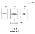
- FIG. 1 depicts a system 100 including a source 102, a power converter 104, and a load 106.
- the term source may comprise a renewable power source, a non-renewable power source, a generator, or a grid, for example. In another possible configuration, the source may comprise another power converter.
- the term load as used herein, may be used to refer to a grid, a machine, or an electrical appliance, for example. In one embodiment, the load 106 is an electric machine that requires power from the input source 102 for operations.
- the power converter 104 comprises a multilevel converter configured to convert power from one form to another.
- the power converter 104 may include legs, such as the leg shown in FIG. 2 , that are coupled between DC-link buses that are configured to transmit power from the input source to the load.
- the legs of the power converter 104 are configured such that regulated power is supplied from the input source to the load, and the operations of the power converter 104 are controlled by a controller 108.
- FIG. 2 a diagrammatical representation a leg 200 of a power converter is depicted.
- the leg 200 of the power converter includes a first string 202 and a second string 204. More particularly, the first string 202 is operatively coupled to the second string 204 to form the leg 200. Furthermore, the first string 202 may be operatively coupled between a first bus 206 and a second bus 208.
- the first bus 206 may include a positive DC bus, and the second bus 208 may include a negative DC bus.
- the first string 202 may be operatively coupled to the second string 204 via a first connecting node 210 and a second connecting node 212.
- first string 202 may include a first branch 214 operatively coupled to a second branch 216 via a third connecting node 218.
- second string 204 may include a first arm 220 operatively coupled to a second arm 222 via an AC phase 224 and an inductor 226.
- the third connecting node 218 may be operatively coupled to a third bus 228.
- the third bus 228 may comprise a direct current bus and more particularly, a middle or center DC bus which may be at a negative potential with respect to the first bus 206 and at a positive potential with respect to the second bus 208.
- the controllable semiconductor switches S 1 , S 2 , S 3 , and S 4 may include a power diode in combination with a thyristor, a silicon controlled rectifier, a gate turnoff thyristor, or an IGBT, for example.
- the first arm 220 and the second arm 222 of the second string 204 may include a plurality of switching modules 234.
- the switching module 234 may be a combination of a plurality of fully controllable semiconductor switches 238 and at least one energy storage device 236.
- the fully controllable semiconductor switches 238 may include insulated gate bipolar transistors (IGBTs), metal oxide semiconductor field effect transistors (MOSFETs), other types of field effect transistors (FETs), gate turn-off thyristors, insulated gate commutated thyristors (IGCTs), injection enhanced gate transistors (IEGTs), or combinations thereof.
- the materials of such switches may comprise silicon, silicon carbide, gallium nitride, or gallium arsenide, for example.
- the switching modules 234 in the first arm 220 and the second arm 222 are selected such that the voltage rating of the leg 200 is met and a minimum voltage step requirement of the power converter is fulfilled.
- the energy storage device 236 may include a capacitor, an ultra-capacitor, a super conducting coil, a battery or any other storage element.
- the fully controllable semiconductor switch 238 may be operatively coupled in series to the energy storage device 236.
- the leg 200 may be employed in a single phase power converter, a two phase power converter, a three phase power converter, and other equivalent multiphase DC to AC, AC to DC, AC to AC, or DC to DC power converters.
- the switching of the semiconductor switches in the first string 202 and the second string 204 may be controlled based on reference value for a controlled variable required at the output terminal. For example, the switches may be controlled to deliver required output power at the output terminals.
- a power converter with the leg 200 may be coupled with another power converter with leg 200 to create a back-to-back power conversion configuration.
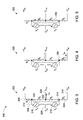
- FIGs. 3-5 depict diagrammatical representations 300, 400, and 500 of different states of a leg of a power converter, such as the leg 200 of FIG. 2 .
- a diagrammatical representation of a leg 302 such as the leg 200 of FIG. 2 , in a first state of switching of the controllable semiconductor switches is presented.
- the first state may also be referred to as a positive state.
- the leg 302 may include a first string 304 and a second string 306.
- the leg 302 may be operatively coupled between a first bus 308 and a second bus 310.
- the first bus 308 may include a positive DC bus
- the second bus 310 may include a negative DC bus.
- the first string 304 may be operatively coupled to the second string 306 via a first connecting node 312 and a second connecting node 314.
- a first arm such as the first arm 220 of FIG. 2 of the second string 306, and a second arm, such as the second arm 222 of FIG. 2 of the second string 306, may be represented by controllable voltage sources Vp 316 and V n 318, respectively.
- the second string 306 may include a plurality of switching modules (not shown).
- the first arm of the second string 306 and the second arm of the second string 306 may be operatively coupled via the fourth bus 320.
- a load such as the load 106, may be coupled to the leg 300 via the fourth bus 320.
- the first string 304 may include a third connecting node 322, which may be operatively coupled to a third bus 324. In the configuration of FIG.
- the first string 304 includes four controllable semiconductor switches represented as S 1 , S 2 , S 3 and S 4 .
- the voltage at the first bus 308 may be represented as +V dc
- the voltage at the second bus 310 may be represented as -V dc .
- the voltage of +V dc at the first bus 308 and the voltage of -V dc at the second bus 310 may be with respect to a virtual ground.
- the voltages across the first bus 308 and the second bus 310 are measured with respect to the third bus 324.
- the voltage at the third bus 324 may be represented as V mid .
- controllable semiconductor switches S 1 and S 3 are activated to allow current to flow therethrough, while the controllable semiconductor switches S 2 and S 4 are maintained in a deactivated state to prevent current from flowing therethrough.
- the activation of controllable semiconductor switches S 1 and S 3 provides a first current flow path 326 between the first bus 308 and the third bus 324 via a corresponding second string 306. Consequently, the second string 306 may be operatively coupled between the first bus 308 and the third bus 324 in the positive state.
- the voltage across the first bus 308 and the third bus 324 may depend on the switching of the fully controllable semiconductor switches corresponding to the plurality of switching modules in the second string 306, such as the switching modules 334 of FIG. 3 .
- the current flowing through the first current flow path 326 is represented as I dc .
- FIG. 4 is a diagrammatical representation 328 of a leg in a second state of switching of the controllable semiconductor switches.
- the second state of switching of the controllable semiconductor switches may also be referred to as a negative state.
- the controllable semiconductor switches S 2 and S 4 may be activated, while controllable semiconductor switches S 1 and S 3 are deactivated.
- the activation of the controllable semiconductor switches S 2 and S 4 results in providing a second current flow path 330 between the third bus 324 and the second bus 310.
- the second string 306 may be operatively coupled between the second bus 310 and the third bus 324 in the negative state.
- FIG. 5 is a diagrammatical representation 332 of a leg in a third state of switching of the controllable semiconductor switches.
- the third state of switching of the controllable semiconductor switches may also be referred to as a zero state.
- the controllable semiconductor switches S 2 and S 3 are activated, while the controllable semiconductor switches S 1 , and S 4 are deactivated.
- the activation of the controllable semiconductor switches S 2 and S 3 results in providing a third current flow path 334.
- This third current flow path 334 may also be referred to as a freewheeling path.
- both ends of the second string 306 may be operatively coupled to each other via the activated controllable semiconductor switches S 2 and S 3 and the third bus 324.
- FIGs. 3-5 represent the three states of switching with reference to a single leg, these three states of switching may be employed simultaneously for a plurality of legs in a two phase power converter, a three-phase power converter, and the like.
- the second string 306 is operatively coupled between the first bus 308 and third bus 324, between the third bus 324 and the second bus 310, or both ends of the second string 306 may be operatively coupled to a third bus 324.
- the second string 306 may have to withstand a maximum voltage of value V dc .
- the first arm of the second string 306 and the second arm of the second string 306 may each have to withstand a maximum voltage of V dc .
- the switching of the plurality of controllable semiconductor switches S 1 , S 2 , S 3 , and S 4 of the first string 304 may operate in combination with the switching of the plurality of switching modules (not shown) in the second string 306.
- the switching of the plurality of switching modules in the second string 306 may include activation and/or deactivation of the fully controllable semiconductor switches.
- the switching modules in the second string 306 and the switches in the first string 304 are controlled by a controller 1108 ( FIG. 11 ) such that regulated power is provided at the output terminal while ensuring that the energy stored in the power converter is maintained at a constant level.
- each leg 200 is connected in parallel between the first bus 206 and the second bus 208.
- the legs 200 are connected such that the first string 202 of each leg is coupled with the first bus 206 on one end and the second bus 208 on another end.
- the first string 202 of each leg 200 is coupled to the third bus 228.
- the voltage of the first bus 206 and the second bus 208 is measured with respect to the third bus 228.
- the fourth bus 320 of each leg 200 is coupled with phases of the load 106. For example, in the case of electric machine drive application via a three-phase converter, each phase (leg 200) of the power converter is coupled to a respective one of the three phases of the electric machine.
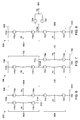
- FIG. 6-9 a diagrammatical representation 600, 700, 800, and 900 of different modes of operation of a three phase power converter, according to the aspects of the present disclosure, are depicted.
- FIGs. 6-9 will be described with respect to FIGs. 3 - 5 .
- the power converter may be operating in one of the three modes depicted in FIG. 6-8 .
- the power converter may be operated in a state as depicted in FIG. 9 , according to one embodiment.
- FIG. 9 it is assumed that an AC input is provided to the power converter. More precisely each of the three phases of an AC input source are connected to a respective leg of the power converter. Depending on the input received from the AC input source, each leg of the power converter operates in at least on mode illustrated in FIGs. 6-9 .
- the modes of operation of the power converter are dependent on the switching pattern of the semiconductor switches and the switching modules.
- the switches and switching modules are controlled by a controller, for example the controller 1108 ( FIG. 11 ), such that the power converter transitions from one mode to another in accordance with the input signal.
- Modes of operation of the power converter are determined by the state of each leg of the power converter. As illustrated in FIG 3-5 , each leg of the power converter can be in either a positive state, a negative state, or a zero state. Steady modes of operation of the power converter include a mode where one or more legs are in the positive state and the other legs are in a negative state. A steady mode of operation also includes a mode where one leg is in a positive state, one leg is in a negative state, and one leg is in a zero state. In comparison, a transient mode involves at least one leg of the power converter being in a transient mode. FIGs 6-9 illustrate steady as well as transient modes of operation of the power converter.
- FIG. 6 illustrates a mode of operation 600 of a converter when two legs are in a positive state and one leg of the converter is in negative state.
- the mode of operation 600 can be termed as mode "a".
- mode a for a three-phase power converter, the legs 602 and 604 are coupled to the positive bus 606 while the leg 608 is coupled to the negative bus 610.
- mode "a" the semiconductor switches S 1 and S 3 of two legs 602 and 604 are switched on and semiconductor switches S 3 and S 4 are switched on for the remaining leg 608.
- the legs 602 and 604 are coupled such that one end is coupled to the positive bus 606 and the other end of the legs is coupled to a third bus 612.
- the leg 608 is coupled to the third bus 612 on one end and to the negative bus 610 on the other end.
- FIG. 7 illustrates a second mode 700 of operation of the power converter with three legs 702, 704, and 708.
- the second mode of operation 700 also termed as mode "b"
- two legs are coupled to a negative bus 710 and a third bus 712, and one leg is coupled to the positive bus 708.
- the legs 704 and 708 are coupled to the third bus 712 and the negative bus 710 while the leg 702 is coupled to the positive bus 706 and the third bus 712.
- FIG. 8 illustrates a third mode 800 of operation of the power converter with three legs 802, 804, and 808.
- the third mode of operation 800 also termed as mode "c"
- one leg is coupled to the positive bus 806 and the third bus 812
- one leg is coupled to the third bus 812 and the negative bus 810
- one leg is coupled on both ends to the third bus 812.
- the leg 802 is coupled to the positive bus 806 and the third bus 812.
- the leg 804 is coupled to the third bus 812 on both ends.
- the leg 808 is coupled to the third bus 812 and the negative bus 810.
- Mode "c" may be considered a transient mode of operation for the power converter.
- the modes of operation illustrated in FIGs 6-7 are considered steady modes of operation of the power converter.
- the energy storage devices in the power converter are configured to receive and store energy from the input source.
- the energy stored in the energy storage devices of the legs of the power converter may be utilized to provide regulated power to the load coupled to the output terminal of the power converter.
- energy storage devices in the legs coupled to the positive bus 806 and the negative bus 810 continue to receive and store energy from the input source. However, the leg in zero state is temporarily de-coupled from the input source.
- the modes of the power converter periodically change from mode "a” to “b” to “c” and back to "a".
- the transition of these modes is carried out with the help of semiconductor switches S 1 , S 2 , S 3 , and S 4 of each leg.
- the four semiconductor switches of each leg are utilized to couple the switching modules to either the positive bus, the negative bus, or the third bus.
- the leg 602 transitions from a positive state to a negative state (represented as 702 in FIG. 7 ).
- the switches S 1 and S 3 corresponding to the leg 602 are activated.
- S 2 , and S 4 are activated.
- the switches S 1 and S 3 need to be deactivated and the switches S 2 and S 4 need to be activated.
- a controller such as the controller 1108 ( FIG. 11 ), may be configured to activate S 2 , and S 4 to facilitate the entry of the power converter into mode "b".
- the leg 702 transitions from a positive state to a zero state (represented as 802, in FIG. 8 ).
- the switch S4 associated with leg 702 needs to be deactivated and a switch S 2 needs to be activated such that S 2 and S 3 for the leg 702 remain activated and move the leg 702 in a zero state.
- the transient mode of operation, or mode "c" is activated during the time frame when the power converter transitions from mode "a" to mode "b".
- FIG. 9 illustrates a fourth mode 900 of operation of the power converter.
- the fourth mode 900 may also be termed as "d" mode of operation of the power converter.
- the legs 902, 904, and 908 are coupled to third bus 912 on both ends.
- the energy stored in energy storage devices of each leg 902, 904, and 908 is provided to the load connected to the output terminal of the power converter.
- the energy storage devices of the power converter are configured to store energy during modes “a”, “b", and “c” of operation.
- mode “d” the power converter is configured to provide power to the electric machine coupled at the output terminals.
- the power provided by the power converter is available through the energy stored in the energy storage devices of the legs of the power converter.
- the controller such as the controller 1108 ( FIG. 11 ), is configured to activate and deactivate appropriate semiconductor switches (S 1 , S 2 , S 3 , S 4 ) from the first string of each leg 200 such that the power converter transitions from either mode "a", mode "b", or mode “c” to mode “d".
- the controller 1108 may be configured to balance energy stored in the first arm 220 and the second arm 222 of each leg 200 in the power converter.
- the controller 1108 is configured to compute a difference between energy stored in the first arm 220 and the second arm 222 of each leg to generate a phase arm reference voltage.
- the phase arm reference voltage is utilized by the controller 1108 to drive a current in the leg 200 such that the energy stored in the first arm 220 and the second arm 222 is balanced.
- the controller 1108 may also be configured to compare energy stored in the energy storage devices with a predetermined threshold value.
- the predetermined threshold value is an indicator of minimum energy required to be stored in the energy storage devices of the power converter.
- the controller is configured to activate and deactivate switches S 1 , S 2 , S 3 , S 4 from the first string of each leg 200 such that the power converter transitions from mode "d" to mode "a", or mode "b", or mode "c". The transition from mode "d” to other modes of operation is dependent on the input received at input terminals of the power converter.
- a method for driving an electric machine with a power converter such as the power converter 104 with a leg 200, is described in conjunction with the flow diagram of FIG. 10 .
- the method includes providing power from an input source to the electric machine through a power converter.
- the power converter for example the power converter 104, includes a leg 200 with a first string 202 and a second string 204.
- the first string 202 includes a plurality of semiconductor switches (S 1 , S 2 , S 3 , and S 4 ) and the second string 204 includes a plurality of switching modules 234.
- the switching modules 234 are configured to provide regulated power to the electric machine coupled to the output terminal of the power converter.
- a system controller (for example, system controller 108) is configured to generate a plurality of activation commands for the semiconductor switches and the switching modules 234.
- the system controller is configured to activate semiconductor switches such that the power converter operates in any of the modes "a", “b", or "c".
- the switching modules 234 that include energy storage devices, for example the capacitive element 236, are configured to stored energy in the energy storage devices 236 in modes “a", "b", and "c". The switching requirements for modes "a”, “b”, and “c” have been explained in conjunction with FIG. 6-8 .
- the system controller 108 is also configured to generate activation commands such that the power converter is transitioned to mode "d" of operation. In mode “d”, all legs of the power converter are coupled to the third bus 228.
- the power converter in this mode, is configured to utilize energy stored in the energy storage devices 236.
- the system controller 108 is configured to provide activation signals to the semiconductor switches and the switching modules in the form of gate trigger signals.
- the activation signals change the mode of operation of the power converter from either mode “a”, or "b", or “c” to mode “d". Switching requirements for mode “d” have been explained in conjunction with FIG. 9 .
- the energy stored in the energy storage devices 236 of the power converter is utilized and provided to the electric machine coupled to the output terminal (for example, via the fourth bus 324).
- the energy provided from the energy storage devices 236 provides the electric machine with substantially high torque at substantially low speeds of operation.
- the controller 108 is configured to transition the power converter from mode “d” to either mode “a", or "b", or "c". The transition from mode "d” is also dependent on the input energy received by the power converter.
- the system controller is also configured to determine if the energy stored in the energy storage devices 236 is below a predetermined threshold value.
- the controller compares energy stored in each of the energy storage devices 236 with the predetermined threshold value.
- the method includes providing activation commands to the plurality of semiconductor switches (S 1 -S 4 ) such that the power converter operates in either mode "a", or "b", or "c".
- the energy storage devices 236 are provided energy in these modes and are available for utilization by the electric machine when the machine is subsequently switched on for operation.
- FIG. 11 depicts a system 1100 for driving an electric machine 1106.
- the system 1100 for driving the electric machine 1106 may include a source 1102, a power converter 1104, and a system controller 1108.
- the source 1102 is coupled to an input terminal of the power converter 1104.
- the source 1102 is configured to provide power to the electric machine 1106 coupled to the output terminal of the power converter 1104.
- the power converter 1104 is configured to convert or regulate input provided by the source 1102 according to the requirements of the electric machine 1106.
- the source 1102 may be placed at a remote location with respect to the electric machine 1106.
- the energy from the source 1102 is provided to the power converter 1104 through buses that couple the source 1102 and the power converter 1104.
- the power converter 1104 and the electric machine 1106 may also be coupled through link buses.
- the power converter 1104 includes at least one leg.
- An example of a leg is illustrated in FIG. 2 .
- the leg 200 includes a first string 202, and a second string 204.
- the first string includes semiconductor switches (S 1 -S 4 ), whereas the second string includes switching modules 234.
- the first string 202 is coupled to the first bus 206 and the second bus 208.
- the second string 204 is coupled to the first string 202 via the first connecting node 210 and second connecting node 212.
- three legs 200 are coupled in parallel between the first bus 206 and the second bus 208.
- the electric machine 1106 is coupled to the second string 204 of each leg 200.
- the first string 202 of each leg is coupled to the third bus 228.
- the system controller 1108 is configured to transition the power converter 1104 from modes “a", or "b", or “c” to mode “d".
- the switching modules 234 are configured to provide stored energy to the electric machine 1106 coupled to the third bus 228.
- the system controller 1108 includes a module "d" activation module 1110 that is configured to determine a current mode of operation of the power converter. Based on the current mode of operation of the power converter, the mode “d” activation module determines the semiconductor switches (S 1 -S 4 ) that need to be activated and deactivated to transition the mode of operation of the power converter to mode "d".
- the system controller 1108 is also configured to balance energy stored in the switching modules 234 of every leg.
- the system controller 1108 computes energy stored in each switching module 234 of each leg 200. Based on a difference between energy stored in each switching module 234, the system controller 1108 drives a current through the leg 200 such that the difference between energy stored in the switching modules 234 is reduced to zero.
- the system for driving an electric machine can include additional filters, and switching device bridges to meet harmonic requirements of the source 1102 and the electric machine 1106.
Landscapes
- Engineering & Computer Science (AREA)
- Power Engineering (AREA)
- Inverter Devices (AREA)
- Dc-Dc Converters (AREA)
Applications Claiming Priority (1)
| Application Number | Priority Date | Filing Date | Title |
|---|---|---|---|
| US14/040,767 US9325273B2 (en) | 2013-09-30 | 2013-09-30 | Method and system for driving electric machines |
Publications (2)
| Publication Number | Publication Date |
|---|---|
| EP2854271A2 true EP2854271A2 (de) | 2015-04-01 |
| EP2854271A3 EP2854271A3 (de) | 2015-09-02 |
Family
ID=51619000
Family Applications (1)
| Application Number | Title | Priority Date | Filing Date |
|---|---|---|---|
| EP14185925.6A Withdrawn EP2854271A3 (de) | 2013-09-30 | 2014-09-23 | Verfahren und System zur Ansteuerung elektrischer Maschinen |
Country Status (5)
| Country | Link |
|---|---|
| US (1) | US9325273B2 (de) |
| EP (1) | EP2854271A3 (de) |
| CN (1) | CN104518686B (de) |
| BR (1) | BR102014023837A2 (de) |
| CA (1) | CA2864566A1 (de) |
Families Citing this family (3)
| Publication number | Priority date | Publication date | Assignee | Title |
|---|---|---|---|---|
| US9515568B2 (en) * | 2014-03-28 | 2016-12-06 | General Electric Company | Power converter with a first string having diodes and a second string having switching units |
| CA2945093C (en) * | 2014-04-09 | 2022-04-19 | Lionel O. Barthold | Multi-module dc-to-dc power transformation system |
| WO2018149489A1 (en) * | 2017-02-15 | 2018-08-23 | Abb Schweiz Ag | Semiconductor switch with magnetic coupling device |
Family Cites Families (45)
| Publication number | Priority date | Publication date | Assignee | Title |
|---|---|---|---|---|
| GB2285523B (en) | 1994-01-08 | 1997-10-15 | Gec Alsthom Ltd | Improvements in or relating to multilevel convertors |
| GB2294821A (en) | 1994-11-04 | 1996-05-08 | Gec Alsthom Ltd | Multilevel converter |
| US6091610A (en) | 1998-04-06 | 2000-07-18 | Lucent Technologies Inc. | System and method for reducing transient switch currents in an asymmetrical half bridge converter |
| US6315080B1 (en) | 2000-01-24 | 2001-11-13 | Paul J. Doran | Converter arrangement for modular motor |
| DE20122923U1 (de) | 2001-01-24 | 2010-02-25 | Siemens Aktiengesellschaft | Stromrichterschaltungen mit verteilten Energiespeichern |
| US6466458B2 (en) | 2001-02-12 | 2002-10-15 | Delta Electronics, Inc. | Asymmetrical full bridge DC-to-DC converter |
| US6577515B2 (en) | 2001-03-02 | 2003-06-10 | Advanced Micro Devices, Inc. | Asymmetric power supply including a fast response converter |
| JP2005073362A (ja) | 2003-08-22 | 2005-03-17 | Rikogaku Shinkokai | 電力変換装置、モータドライブ装置、btbシステムおよび系統連系インバータシステム |
| US20050139259A1 (en) | 2003-12-30 | 2005-06-30 | Robert Steigerwald | Transformerless power conversion in an inverter for a photovoltaic system |
| US7219673B2 (en) | 2004-08-25 | 2007-05-22 | Curtiss-Wright Electro-Mechanical Corporation | Transformerless multi-level power converter |
| EP1750363A1 (de) | 2005-08-03 | 2007-02-07 | Abb Research Ltd. | Mehrpegel- Wechselstrom/Gleichstromwandler für Traktionsanwendungen |
| EP1750361A1 (de) | 2005-08-03 | 2007-02-07 | ABB Research Ltd | Anordnung eines Multilevel-Converters und ihre Verwendung |
| US7969755B2 (en) | 2005-09-09 | 2011-06-28 | Siemens Aktiengesellschaft | Apparatus for electrical power transmission |
| DE102005045090B4 (de) | 2005-09-21 | 2007-08-30 | Siemens Ag | Verfahren zur Steuerung eines mehrphasigen Stromrichters mit verteilten Energiespeichern |
| US8044537B2 (en) | 2006-06-28 | 2011-10-25 | Abb Technology Ltd. | Modular HVDC converter |
| US8008805B2 (en) | 2006-12-07 | 2011-08-30 | Nissan Motor Co., Ltd. | Power conversion apparatus and motor drive system |
| DE112006004197A5 (de) | 2006-12-08 | 2009-11-12 | Siemens Aktiengesellschaft | Steuerung eines modularen Stromrichters mit verteilten Energiespeichern |
| CN101548459B (zh) | 2006-12-08 | 2012-07-04 | 西门子公司 | 变流器相模块的有功功率平衡的产生 |
| WO2008067785A1 (de) | 2006-12-08 | 2008-06-12 | Siemens Aktiengesellschaft | Vorrichtung zum umrichten eines elektrischen stromes |
| ES2664868T3 (es) | 2007-01-17 | 2018-04-23 | Siemens Aktiengesellschaft | Control de un ramal de módulo de fase de un convertidor multinivel |
| WO2009068698A1 (es) | 2007-11-30 | 2009-06-04 | Ingeteam Energy, S.A. | Circuito electrico para convertir energia electrica continua en energia electrica alterna |
| WO2009086927A1 (en) | 2008-01-08 | 2009-07-16 | Abb Technology Ag | A method for controlling a voltage source converter and a voltage converting apparatus |
| EP2107672A1 (de) | 2008-03-31 | 2009-10-07 | SMA Solar Technology AG | Dreiphasiger Wechselrichter ohne Verbindung zwischen dem Neutralleiter des Netzes und dem Mittelpunkt des Zwischenkreises |
| US8717786B2 (en) | 2008-06-09 | 2014-05-06 | Abb Technology Ag | Plant for transmitting electric power utilizing asymmetric operation of voltage source converters |
| US7830681B2 (en) | 2008-09-24 | 2010-11-09 | Teco-Westinghouse Motor Company | Modular multi-pulse transformer rectifier for use in asymmetric multi-level power converter |
| US8254076B2 (en) | 2009-06-30 | 2012-08-28 | Teco-Westinghouse Motor Company | Providing modular power conversion |
| JP4969614B2 (ja) | 2009-07-21 | 2012-07-04 | 株式会社日立製作所 | 電力変換装置 |
| EP2290799A1 (de) | 2009-08-25 | 2011-03-02 | Converteam Technology Ltd | Bidirektionale mehrstufige AC-DC Wandleranordnungen |
| CN102741771B (zh) * | 2009-10-29 | 2015-03-25 | 瓦茨更多有限公司 | 能量收集系统和方法 |
| US8228695B2 (en) | 2009-11-16 | 2012-07-24 | General Electric Company | Multilevel converter operation |
| EP2348627A1 (de) * | 2010-01-25 | 2011-07-27 | ABB Research Ltd. | Wandlerschaltung sowie Verfahren zum Betreiben einer mehrstufigen Wandlerschaltung |
| US8395280B2 (en) | 2010-02-16 | 2013-03-12 | Infineon Technologies Ag | Circuit arrangement including a multi-level converter |
| CN102859826B (zh) * | 2010-02-23 | 2015-09-09 | Abb研究有限公司 | 一种有能力给电池充电的电站 |
| US8294306B2 (en) | 2010-03-16 | 2012-10-23 | Indian Institute Of Technology Madras | DC capacitor balancing |
| EP2650999A3 (de) | 2010-04-08 | 2015-11-04 | Alstom Technology Ltd | Spannungsgespeister Multi-Modul-Umrichter für ein HGÜ-System |
| FI122161B (fi) | 2010-04-15 | 2011-09-15 | Abb Oy | Järjestely ja menetelmä taajuusmuuttajamoduulien ohjaamiseksi |
| EP2559145B1 (de) | 2010-04-15 | 2018-02-28 | General Electric Technology GmbH | Hybrider 2-punkt und multilevel hgü umrichter |
| WO2012016592A1 (de) | 2010-08-05 | 2012-02-09 | Siemens Aktiengesellschaft | Verfahren zur spannungssteuerung eines multilevel-umrichters und steueranordnung für einen multilevel-umrichter |
| CN102158112B (zh) * | 2011-03-03 | 2013-01-02 | 山东大学 | 一种模块化多电平变换器的综合控制系统及其方法 |
| US9520741B2 (en) * | 2011-11-28 | 2016-12-13 | General Electric Company | System for charging electrical storage device and method of making same |
| DE102011122058A1 (de) * | 2011-12-22 | 2013-06-27 | Andreas Stihl Ag & Co. Kg | "Rückentragbarer Akkupack" |
| WO2013135277A1 (en) | 2012-03-14 | 2013-09-19 | Abb Technology Ltd. | A clamped modular power converter |
| WO2013137749A1 (en) | 2012-03-16 | 2013-09-19 | Auckland Uniservices Limited | Electrical systems with inductive power transfer-based energy balancing |
| CN103208929B (zh) * | 2013-04-22 | 2016-06-08 | 广东电网公司电力科学研究院 | 基于mmc的电子电力变压器 |
| CN103280952B (zh) * | 2013-04-23 | 2016-01-27 | 浙江大学 | 一种模块化多电平换流器的控制系统及其应用方法 |
-
2013
- 2013-09-30 US US14/040,767 patent/US9325273B2/en not_active Expired - Fee Related
-
2014
- 2014-09-18 CA CA 2864566 patent/CA2864566A1/en not_active Abandoned
- 2014-09-23 EP EP14185925.6A patent/EP2854271A3/de not_active Withdrawn
- 2014-09-25 BR BR102014023837A patent/BR102014023837A2/pt not_active Application Discontinuation
- 2014-09-29 CN CN201410513477.XA patent/CN104518686B/zh not_active Expired - Fee Related
Also Published As
| Publication number | Publication date |
|---|---|
| CA2864566A1 (en) | 2015-03-30 |
| EP2854271A3 (de) | 2015-09-02 |
| US20150091488A1 (en) | 2015-04-02 |
| CN104518686B (zh) | 2019-06-14 |
| BR102014023837A2 (pt) | 2016-05-24 |
| US9325273B2 (en) | 2016-04-26 |
| CN104518686A (zh) | 2015-04-15 |
Similar Documents
| Publication | Publication Date | Title |
|---|---|---|
| US11201565B2 (en) | Conversion circuit, control method, and power supply device | |
| US9479075B2 (en) | Multilevel converter system | |
| EP2713495B1 (de) | Mehrstufiges Wandlersystem | |
| US9252681B2 (en) | Power converter with a first string having controllable semiconductor switches and a second string having switching modules | |
| US10530237B2 (en) | Energy storage system for renewable energy source | |
| EP2400619B1 (de) | Kostengünstige Stromquellenwandler für eine Stromerzeugungsvorrichtung | |
| EP2323248B1 (de) | Betrieb eines dreistufigen Wandlers | |
| US20150229227A1 (en) | Multi-phase AC/AC Step-down Converter for Distribution Systems | |
| CN108702105B (zh) | 用于模块化多电平换流器的双子模块和包括该双子模块的模块化多电平换流器 | |
| US9431918B2 (en) | Grounding scheme for modular embedded multilevel converter | |
| KR20120041791A (ko) | Dc-ac 인버터 장치, 특히 태양전지 인버터 | |
| KR20140142825A (ko) | 멀티 레벨 인버터 | |
| EP2993777B1 (de) | Mehrpegelumrichter | |
| EP2924867B1 (de) | Mehrpegelumrichter | |
| Gonzalez-Longatt et al. | Power converters dominated power systems | |
| Stieneker et al. | Analysis of wind turbines connected to medium-voltage DC grids | |
| US9325273B2 (en) | Method and system for driving electric machines | |
| EP2840699A2 (de) | Mehrstufiges Wandlersystem | |
| KR101312959B1 (ko) | 전력 변환 장치 | |
| Cheng et al. | The topology analysis and compare of high-frequency power electronic transformer | |
| Ukil et al. | Components and Architectures of DC Grid for Various Applications | |
| Giessmann et al. | The Simultaneous Use of Two Alternative Neutral Point Current Paths in a 3-Level ANPC Topology–Benefits and Challenges in High Power Applications | |
| KUMAR et al. | LOAD SHARING WITH PARALLEL INVERTERS FOR INDUCTION MOTOR DRIVE APPLICATION | |
| KR20130052364A (ko) | 전력변환장치 |
Legal Events
| Date | Code | Title | Description |
|---|---|---|---|
| PUAI | Public reference made under article 153(3) epc to a published international application that has entered the european phase |
Free format text: ORIGINAL CODE: 0009012 |
|
| 17P | Request for examination filed |
Effective date: 20140923 |
|
| AK | Designated contracting states |
Kind code of ref document: A2 Designated state(s): AL AT BE BG CH CY CZ DE DK EE ES FI FR GB GR HR HU IE IS IT LI LT LU LV MC MK MT NL NO PL PT RO RS SE SI SK SM TR |
|
| AX | Request for extension of the european patent |
Extension state: BA ME |
|
| PUAL | Search report despatched |
Free format text: ORIGINAL CODE: 0009013 |
|
| AK | Designated contracting states |
Kind code of ref document: A3 Designated state(s): AL AT BE BG CH CY CZ DE DK EE ES FI FR GB GR HR HU IE IS IT LI LT LU LV MC MK MT NL NO PL PT RO RS SE SI SK SM TR |
|
| AX | Request for extension of the european patent |
Extension state: BA ME |
|
| RIC1 | Information provided on ipc code assigned before grant |
Ipc: H02M 1/32 20070101AFI20150730BHEP Ipc: H02M 5/42 20060101ALI20150730BHEP Ipc: H02P 27/14 20060101ALI20150730BHEP Ipc: H02J 7/02 20060101ALI20150730BHEP Ipc: H02M 7/493 20070101ALI20150730BHEP Ipc: H02P 1/16 20060101ALN20150730BHEP Ipc: H02P 27/16 20060101ALI20150730BHEP |
|
| R17P | Request for examination filed (corrected) |
Effective date: 20160301 |
|
| RBV | Designated contracting states (corrected) |
Designated state(s): AL AT BE BG CH CY CZ DE DK EE ES FI FR GB GR HR HU IE IS IT LI LT LU LV MC MK MT NL NO PL PT RO RS SE SI SK SM TR |
|
| STAA | Information on the status of an ep patent application or granted ep patent |
Free format text: STATUS: EXAMINATION IS IN PROGRESS |
|
| 17Q | First examination report despatched |
Effective date: 20191111 |
|
| RIC1 | Information provided on ipc code assigned before grant |
Ipc: H02P 27/16 20060101ALI20200630BHEP Ipc: H02P 27/14 20060101ALI20200630BHEP Ipc: H02M 5/42 20060101ALI20200630BHEP Ipc: H02P 1/16 20060101ALN20200630BHEP Ipc: H02J 7/02 20160101ALI20200630BHEP Ipc: H02M 1/32 20070101AFI20200630BHEP Ipc: H02M 7/493 20070101ALI20200630BHEP |
|
| RIC1 | Information provided on ipc code assigned before grant |
Ipc: H02P 27/14 20060101ALI20200715BHEP Ipc: H02P 27/16 20060101ALI20200715BHEP Ipc: H02P 1/16 20060101ALN20200715BHEP Ipc: H02J 7/02 20160101ALI20200715BHEP Ipc: H02M 5/42 20060101ALI20200715BHEP Ipc: H02M 7/493 20070101ALI20200715BHEP Ipc: H02M 1/32 20070101AFI20200715BHEP |
|
| RIC1 | Information provided on ipc code assigned before grant |
Ipc: H02J 7/02 20160101ALI20200728BHEP Ipc: H02P 27/16 20060101ALI20200728BHEP Ipc: H02M 7/493 20070101ALI20200728BHEP Ipc: H02P 27/14 20060101ALI20200728BHEP Ipc: H02P 1/16 20060101ALN20200728BHEP Ipc: H02M 1/32 20070101AFI20200728BHEP Ipc: H02M 5/42 20060101ALI20200728BHEP |
|
| RIC1 | Information provided on ipc code assigned before grant |
Ipc: H02P 27/16 20060101ALI20200923BHEP Ipc: H02P 1/16 20060101ALN20200923BHEP Ipc: H02P 27/14 20060101ALI20200923BHEP Ipc: H02J 7/02 20160101ALI20200923BHEP Ipc: H02M 7/493 20070101ALI20200923BHEP Ipc: H02M 1/32 20070101AFI20200923BHEP Ipc: H02M 5/42 20060101ALI20200923BHEP |
|
| RIC1 | Information provided on ipc code assigned before grant |
Ipc: H02P 27/14 20060101ALI20200930BHEP Ipc: H02M 7/493 20070101ALI20200930BHEP Ipc: H02M 5/42 20060101ALI20200930BHEP Ipc: H02J 7/02 20160101ALI20200930BHEP Ipc: H02M 1/32 20070101AFI20200930BHEP Ipc: H02P 27/16 20060101ALI20200930BHEP Ipc: H02P 1/16 20060101ALN20200930BHEP |
|
| GRAP | Despatch of communication of intention to grant a patent |
Free format text: ORIGINAL CODE: EPIDOSNIGR1 |
|
| STAA | Information on the status of an ep patent application or granted ep patent |
Free format text: STATUS: GRANT OF PATENT IS INTENDED |
|
| RIC1 | Information provided on ipc code assigned before grant |
Ipc: H02P 27/16 20060101ALI20201026BHEP Ipc: H02P 1/16 20060101ALN20201026BHEP Ipc: H02P 27/14 20060101ALI20201026BHEP Ipc: H02M 5/42 20060101ALI20201026BHEP Ipc: H02M 7/493 20070101ALI20201026BHEP Ipc: H02M 1/32 20070101AFI20201026BHEP Ipc: H02J 7/02 20160101ALI20201026BHEP |
|
| RIC1 | Information provided on ipc code assigned before grant |
Ipc: H02M 1/32 20070101AFI20201030BHEP Ipc: H02M 7/493 20070101ALI20201030BHEP Ipc: H02J 7/02 20160101ALI20201030BHEP Ipc: H02P 1/16 20060101ALN20201030BHEP Ipc: H02M 5/42 20060101ALI20201030BHEP Ipc: H02P 27/14 20060101ALI20201030BHEP Ipc: H02P 27/16 20060101ALI20201030BHEP |
|
| INTG | Intention to grant announced |
Effective date: 20201117 |
|
| STAA | Information on the status of an ep patent application or granted ep patent |
Free format text: STATUS: THE APPLICATION IS DEEMED TO BE WITHDRAWN |
|
| 18D | Application deemed to be withdrawn |
Effective date: 20210330 |