EP2853924A1 - Radiographic image reading device, radiographic image reading program, and radiographic image reading method - Google Patents
Radiographic image reading device, radiographic image reading program, and radiographic image reading method Download PDFInfo
- Publication number
- EP2853924A1 EP2853924A1 EP14177079.2A EP14177079A EP2853924A1 EP 2853924 A1 EP2853924 A1 EP 2853924A1 EP 14177079 A EP14177079 A EP 14177079A EP 2853924 A1 EP2853924 A1 EP 2853924A1
- Authority
- EP
- European Patent Office
- Prior art keywords
- excitation light
- radiographic image
- resolution
- scanning
- storage phosphor
- Prior art date
- Legal status (The legal status is an assumption and is not a legal conclusion. Google has not performed a legal analysis and makes no representation as to the accuracy of the status listed.)
- Withdrawn
Links
Images


Classifications
-
- G—PHYSICS
- G01—MEASURING; TESTING
- G01T—MEASUREMENT OF NUCLEAR OR X-RADIATION
- G01T1/00—Measuring X-radiation, gamma radiation, corpuscular radiation, or cosmic radiation
- G01T1/16—Measuring radiation intensity
- G01T1/20—Measuring radiation intensity with scintillation detectors
- G01T1/2012—Measuring radiation intensity with scintillation detectors using stimulable phosphors, e.g. stimulable phosphor sheets
- G01T1/2014—Reading out of stimulable sheets, e.g. latent image
Definitions
- the present invention relates to a radiographic image reading device, a radiographic image reading program, and a radiographic image reading method.
- a storage phosphor a photostimulable phosphor
- a portion of the radiation energy is stored in the storage phosphor.
- an excitation light such as a laser light or the like
- the storage phosphor is photostimulated and luminesces in accordance with the stored energy.
- radiographic image reading devices that employ storage phosphors are used for clinical applications, non-destructive testing in industry and the like.
- image information of a radiographic image of an imaging subject such as a weld or the like, is temporarily recorded in a sheet (an image plate IP, which is a storage phosphor sheet) that includes a storage phosphor layer.
- the storage phosphor sheet IP is scanned with excitation light, and photostimulated luminescence light that is produced is read photoelectrically.
- JP-A Japanese Patent Application Laid-Open
- JP-A No. 2004-163792 describes a radiographic image reading device that employs standard-resolution storage phosphor sheets and high-resolution storage phosphor sheets.
- a polygon mirror for illuminating the excitation light onto the surface of the storage phosphor sheet is rotated at a low speed, and when an image is being read at low resolution, the polygon mirror is rotated at a high speed.
- JP-A No. 2010-239480 describes a technology that eliminates stripe irregularities (linear irregularities) in a radiographic image. This technology eliminates the linear irregularities by image correction from an original image that contains the linear irregularities, which has been read by a radiographic image reading device.
- JP-A No. 2010-239480 because irregularities are eliminated in the image data by the image correction, there is a risk that portions of a scanning target may be mistakenly removed. For example, in a case in which a portion of the scanning target is a fault in a weld or the like, due to the fault being linear, the fault may be treated as an irregularity and corrected.
- the present invention has been made in view of the above circumstances and provides a radiographic image reading device, a radiographic image reading program, and a radiographic image reading method.
- a radiographic image reading device which includes: reading means that photoelectrically read photostimulated luminescence light produced from a storage phosphor sheet illuminated with excitation light, the storage phosphor sheet, at which a radiographic image is stored, being scanned by scanning means using the excitation light; and control means that control the reading means to so as cause the reading means, in a case of reading at a first resolution, to read with excitation light at a first scanning speed and a first intensity and, in a case of reading at a second resolution that is a higher resolution than the first resolution, to read with excitation light at a second scanning speed that is slower than the first scanning speed and a second intensity that is smaller than the first intensity.
- a beam diameter of the excitation light at a surface of the storage phosphor sheet may be the same regardless of the resolution, a pixel size of the first resolution may be larger than the beam diameter of the excitation light, and a pixel size of the second resolution may be smaller than the beam diameter of the excitation light.
- a second intensity may be 2.0 mW or more at a surface of the storage phosphor sheet.
- a second intensity at a surface of the storage phosphor sheet may be 30% or less of the first intensity at the surface of the storage phosphor sheet.
- a beam diameter of the excitation light may be 30 ⁇ m
- a preferable pixel size of the first resolution may be 100 ⁇ m
- a pixel size of the second resolution may be 25 ⁇ m.
- a radiographic image reading program that causes a computer to function as the control means of the radiographic image reading device according to the aspect of the present invention.
- a radiographic image reading method which includes, controlling, by controlling means, reading means that photoelectrically read photostimulated luminescence light produced from a storage phosphor sheet illuminated with excitation light, the storage phosphor sheet, at which a radiographic image is stored, being scanned by scanning means using the excitation light, so as to cause the reading means, in a case of reading at a first resolution, to read with excitation light at a first scanning speed and a first intensity and, in a case of reading at a second resolution that is a higher resolution than the first resolution, to read with excitation light at a second scanning speed that is slower than the first scanning speed and a second intensity that is smaller than the first intensity.
- image quality can be raised and scanning irregularities can be reduced.
- Fig. 1 is a vertical sectional diagram showing the schematic structure of a radiographic image reading device 10 that reads image information of a radiographic image recorded at a storage phosphor sheet IP (hereinafter referred to as "radiographic image information").
- the radiographic image reading device 10 according to the present exemplary embodiment may be, for example, a radiographic image reading device that reads radiographic image information recorded at storage phosphor sheets IP in a computed radiography (CR) system for industrial applications, or the like.
- CR computed radiography
- a touch panel 32 is provided at an upper portion of a casing 30 that structures the exterior of the radiographic image reading device 10.
- the touch panel 32 has the functions of an operation portion and a monitor.
- Each cassette 34 includes a rectangular case 40, which accommodates a storage phosphor sheet IP, and a cover body 44, which is capable of opening and closing an opening portion 42 of the case 40.
- Support stands 46 on which the cassettes 34 are placed, are provided in the cassette loading portions 36a to 36d.
- Shutter members 48 are also provided in the cassette loading portions 36a to 36d, to be capable of opening and closing. Each shutter member 48 is for shielding the interior of the casing 30 from light.
- Cassette position fixing mechanisms (not shown in the drawings) and cover body opening-and-closing mechanisms (not shown in the drawings) are incorporated in the cassette loading portions 36a to 36d. Each cassette position fixing mechanism fixes the position of the cassette 34, and each cover body opening-and-closing mechanism opens and closes the cover body 44 of the cassette 34.
- An ascending-and-descending sheet-feeding unit 50 is installed at the interior of the cassette loading portions 36a to 36d.
- the ascending-and-descending sheet-feeding unit 50 is disposed in arbitrary correspondence with one of the cassette loading portions 36a to 36d.
- the ascending-and-descending sheet-feeding unit 50 has functions for extracting the storage phosphor sheet IP from the arbitrary cassette 34 and returning the storage phosphor sheet IP into the cassette 34 after the storage phosphor sheet IP has been read and erased.
- the ascending-and-descending sheet-feeding unit 50 is provided with a sheet body sheet-feeding mechanism 52 and a raising-and-lowering mechanism 54.
- the sheet body sheet-feeding mechanism 52 includes rollers for conveying the storage phosphor sheets IP one sheet at a time, and the raising-and-lowering mechanism 54 is capable of raising and lowering the sheet body sheet-feeding mechanism 52 in an up-and-down direction (the direction of arrow A).
- a main conveyance path 60 for conveying each storage phosphor sheet IP is linked to the sheet body sheet-feeding mechanism 52 of the ascending-and-descending sheet-feeding unit 50.
- the main conveyance path 60 extends downward from the ascending-and-descending sheet-feeding unit 50, then curves at a lower portion of the casing 30, and reaches a reading conveyance path 70 that extends in the horizontal direction.
- a first roller pair 80 and a second roller pair 82 that structure the reading conveyance path 70 nip the storage phosphor sheet IP and convey the storage phosphor sheet IP in the direction of arrow Y for sub-scanning.
- the first roller pair 80 and second roller pair 82 used in the present exemplary embodiment are rollers whose external periphery faces are fabricated of rubber.
- the reading conveyance path 70 curves and extends upward, and connects with a withdrawal conveyance path 94 that extends in the horizontal direction.
- One end of an erasure conveyance path 96 connects between the reading conveyance path 70 and the withdrawal conveyance path 94.
- the other end of the erasure conveyance path 96 connects with the main conveyance path 60, and the erasure conveyance path 96 supplies a storage phosphor sheet IP conveyed from the withdrawal conveyance path 94 to the main conveyance path 60.
- An excitation light scanning unit 64 and an upper reading unit 66 are disposed at an upper portion of an inner periphery side of the reading conveyance path 70 that curves upward.
- Fig. 2A and Fig. 2B are structural diagrams showing an example of the structure of the excitation light scanning unit 64.
- Fig. 2A shows a plan view of the excitation light scanning unit 64 and
- Fig. 2B shows a side view of the excitation light scanning unit 64.
- the excitation light scanning unit 64 is provided with a light source 12, and a diverging lens system 13 for converting excitation light L, which is a laser beam emitted from the light source 12, to divergent light.
- the excitation light L is made divergent by the diverging lens system 13.
- the light source 12 may be, for example, a laser diode or the like.
- the excitation light scanning unit 64 is provided with a rotating polygon mirror 14, a first lens 16, a second lens 17, and a reflecting mirror 18.
- the rotating polygon mirror 14 is for reflectively deflecting the excitation light L diverged by the diverging lens system 13 toward a surface (a scanning face) of the storage phosphor sheet IP.
- the first lens 16 and second lens 17 are disposed subsequent to the rotating polygon mirror 14 and are included in a scanning focusing optical system that focuses the excitation light L on the storage phosphor sheet IP.
- the reflecting mirror 18 is for reflecting the excitation light L toward the storage phosphor sheet IP.
- the excitation light L emitted from the light source 12 is temporarily made divergent by the diverging lens system 13, and then reflected by deflecting faces provided at outer periphery faces of the rotating polygon mirror 14.
- the excitation light L reflected by the deflecting faces of the rotating polygon mirror 14 passes through the first lens 16 and second lens 17, is reflected by the reflecting mirror 18 and focused on the storage phosphor sheet IP, and exposes the storage phosphor sheet IP by scanning in a main scanning direction. Meanwhile, the storage phosphor sheet IP is being driven in the sub-scanning direction, which is orthogonal to the main scanning direction in which the excitation light L is scanning, by a driving unit (see Fig. 1 ). Thus, the surface of the storage phosphor sheet IP is scanned with the excitation light L. Photostimulated luminescence light, containing the radiographic image information, is outputted from the storage phosphor sheet IP on which the excitation light L is illuminated.
- the upper reading unit 66 is provided with a condensing guide 84 and a photoelectric converter 86.
- the condensing guide 84 includes a transparent member such as an acrylic plate or the like, of which an incidence face at a lower end portion thereof is disposed in a vicinity between the first roller pair 80 and the second roller pair 82.
- the photoelectric converter 86 includes a photomultiplier or the like that is connected to an emission face at an upper end portion of the condensing guide 84.
- a condensing mirror 88 is disposed close to the incidence face of the condensing guide 84.
- the condensing mirror 88 is for efficiently directing the photostimulated luminescence light into the incidence face.
- the photoelectric converter 86 converts the photostimulated luminescence light that has been guided through the condensing guide 84 to electronic signals.
- portions of the photoelectric converter 86 other than a light incidence portion (a photoelectric surface) are covered with a magnetic shield member 90.
- a member with high magnetic permeability is employed as the magnetic shield member 90.
- permalloy an oriented electrical steel plate, an iron plate (pure iron) or the like may be used, or an alternative material may be used.
- permalloy is most excellently employed as the magnetic shield member 90.
- a control circuit 120 and an erasure unit 122 are disposed between the withdrawal conveyance path 94 and the erasure conveyance path 96.
- the control circuit 120 controls the radiographic image reading device 10 as a whole.
- the erasure unit 122 eliminates radiation energy remaining in a storage phosphor sheet IP from which the radiographic image information has been read.
- the erasure unit 122 accommodates a plural number of erasure light sources 126 in a case 124. Each erasure light source 126 is formed of a cold-cathode fluorescent tube or the like.
- the conveyance direction in the radiographic image reading device 10 is the sub-scanning direction (the direction of arrow L1 in Fig. 3A ), corresponding to the longest direction of a storage phosphor sheet IP (i.e., of a radiographic image recorded at the storage phosphor sheet IP), and the direction orthogonal to the longest direction of the storage phosphor sheet IP (the direction of arrow W1 in Fig. 3A ) is the main scanning direction.
- Each storage phosphor sheet IP is accommodated in the cassette 34 facing to the lower side, and the cassette 34 is loaded in the cassette loading portions 36a to 36d (see Fig. 1 ).
- the cassette 34 loaded in the cassette loading portions 36a to 36d is fixed in position by the mechanism that fixes the position of the cassette 34, after which the cover body 44 of the cassette 34 is opened and the storage phosphor sheet IP is sheet-fed from the cassette 34 by the ascending-and-descending sheet-feeding unit 50.
- the sheet-fed storage phosphor sheet IP is conveyed by the main conveyance path 60 and is provided to the reading conveyance path 70.
- the storage phosphor sheet IP is nipped by the first and second roller pairs 80 and 82 and is conveyed for sub-scanning in the direction of arrow Y.
- the excitation light scanning unit 64 disposed above the reading conveyance path 70 deflects the excitation light L emitted from the light source 12 in the main scanning direction with the rotating polygon mirror 14, thus scanning a storage phosphor layer (not shown in the drawings) of the storage phosphor sheet IP.
- the storage phosphor layer of the storage phosphor sheet IP illuminated with the excitation light L outputs photostimulated luminescence light containing radiographic image information.
- the photostimulated luminescence light outputted from the storage phosphor layer of the storage phosphor sheet IP is incident on the incidence surface of the condensing guide 84 provided at the upper reading unit 66 directly, and is reflected by the condensing mirror 88 and made incident on the incidence surface. Hence, the light is directed through the emission surface of the condensing guide 84 to the photoelectric converter 86 and is converted to electronic signals.
- the electronic signals relating to the radiographic image information that are obtained by the photoelectric converter 86 are transferred to the control circuit 120 or, via a wired or wireless communications circuit or the like, to external equipment or the like.
- the storage phosphor sheet IP for which reading has been completed is temporarily conveyed from the reading conveyance path 70 to the withdrawal conveyance path 94, and then provided to the erasure conveyance path 96. While a storage phosphor sheet IP for which reading has been completed is being temporarily conveyed to the withdrawal conveyance path 94, another storage phosphor sheet IP may be provided to the reading conveyance path 70. Thus, reading processes may be carried out concurrently.
- An erasure light Q from the erasure light sources 126 provided in the erasure unit 122 is illuminated at the storage phosphor layer of the storage phosphor sheet IP provided to the erasure conveyance path 96.
- radiographic image information remaining in the storage phosphor layer is erased.
- the erased storage phosphor sheet IP is conveyed via the main conveyance path 60 to the raising-and-lowering mechanism 54, and is then returned to the predetermined cassette 34.
- Fig. 3A and Fig. 3B show descriptive diagrams for describing scanning irregularities.
- Fig. 3A is a conceptual view illustrating scanning irregularities that are produced in a read radiographic image.
- Fig. 3B is a descriptive view showing image densities (QL values) in the sub-scanning direction of the radiographic image of Fig. 3A in which scanning irregularities are produced.
- the scanning irregularities are produced along the main scanning direction of the radiographic image, and image densities (QL values) are higher at the scanning irregularities.
- Causes for the occurrence of scanning irregularities include: variations in the rotation speeds of motors (not shown in the drawings) that are used for sub-scanning conveyance of the storage phosphor sheets IP; eccentricity of the roller pairs 80 and 82 and the like that are used for conveying the storage phosphor sheets IP; load variations when a storage phosphor sheet IP is fed to the roller pairs 80 and 82; load variations when a storage phosphor sheet IP leaves the roller pairs 80 and 82; and the like.
- the production of scanning irregularities is suppressed while the radiographic image information is being read.
- the production of scanning irregularities is suppressed by the control circuit 120 controlling driving of the excitation light scanning unit 64 and controlling the power of the excitation light.
- Fig. 4 is a schematic diagram of an example of principal structures for suppressing the production of scanning irregularities in the radiographic image reading device 10 in accordance with the present invention.
- the control circuit 120 is provided with a control section 20, a resolution setting section 22, a light source control section 24, a motor driving circuit 26 and an interface section 28.
- the control section 20, resolution setting section 22, light source control section 24, motor driving circuit 26 and interface section 28 are connected by a bus 29 to enable exchanges of various kinds of information.
- the control section 20 is structured by a microcomputer and is provided with a central processing unit (CPU), a read-only memory (ROM), a random access memory (RAM) and a hard disk drive (HDD).
- the CPU executes reading control processing, which is described in detail below, by executing a program memorized in the ROM.
- the control section 20 is not limited to the structure shown in Fig. 4 and may be realized by, for example, an application-specific integrated circuit (ASIC), a programmable logic device or the like.
- ASIC application-specific integrated circuit
- the resolution setting section 22 specifies a resolution for reading a radiographic image.
- two modes are provided as resolutions for reading the radiographic image-a high-resolution mode and a low-resolution mode.
- the high-resolution mode has a higher resolution than the low-resolution mode, specifically, a pixel size of 25 ⁇ m/pixel.
- the low-resolution mode has a lower resolution than the high-resolution mode, specifically, a pixel size of 100 ⁇ m/pixel. Thus, the pixel size is larger in the low-resolution mode than in the high-resolution mode.
- pixel size includes a value, for both the main scanning direction and the sub-scanning direction, for which a scanning width of the storage phosphor sheet IP is divided by a number of pixels.
- a reading speed is slower in the high-resolution mode than in the low-resolution mode.
- the designated resolution (the high-resolution mode or the low-resolution mode) is specified at the resolution setting section 22.
- the light source control section 24 has a function for controlling the light source 12 of the excitation light scanning unit 64.
- the light source control section 24 is controlled by the control section 20, and thus the intensity (laser power) of the excitation light from the light source 12 is controlled.
- a method of control of the intensity of the excitation light is not particularly limited; for example, in a case in which the light source 12 is a laser diode, the current value of a driving current may be controlled.
- the motor driving circuit 26 has a function for driving (rotating) the rotating polygon mirror 14 of the excitation light scanning unit 64.
- the motor driving circuit 26 is controlled by the control section 20, and thus the rotation speed of the rotating polygon mirror 14 is controlled.
- the scanning speed at which the surface of the storage phosphor sheet IP is scanned in the sub-scanning direction is controlled, and the reading speed (sampling rate) of the radiographic image is controlled.
- the control section 20 controls the rotation speed of the rotating polygon mirror 14.
- the rotation speed of the rotating polygon mirror 14 is denoted as a rotation frequency (RPM). The greater the rotation frequency, the faster the rotation speed and the faster the scanning speed. On the other hand, the lower the rotation frequency, the slower the rotation speed and the slower the scanning speed.
- the interface section 28 is an interface that exchanges information with external equipment.
- Fig. 5A to Fig. 5C show examples of correspondences between the intensity of excitation light and scanning irregularity intensities (QL values) in the high-resolution mode and the low-resolution mode.
- Fig. 5A is a graph showing an example of correspondences between intensities of excitation light and scanning irregularity intensities (QL values) in a high-resolution mode and a low-resolution mode.
- Fig. 5B is a table showing an example of the correspondence between the intensity of excitation light and scanning irregularities in the high-resolution mode
- Fig. 5C is a table showing an example of the correspondence between the intensity of excitation light and scanning irregularities in the low-resolution mode.
- Fujifilm Imaging Plate Industrial UR-1 fabricated by Fujifilm Corporation
- Fujifilm Imaging Plate Industrial ST-VI fabricated by Fujifilm Corporation
- Reading conditions in the high-resolution mode are: pixel size, 25 ⁇ m/pixel; scanning speed (reading speed), 0.7 ⁇ s/pixel; excitation light wavelength, 660 nm; and half-amplitude beam diameter of the excitation light, 30 ⁇ m.
- Reading conditions in the low-resolution mode are: pixel size, 100 ⁇ m/pixel; scanning speed (reading speed), 1.0 ⁇ s/pixel; excitation light wavelength, 660 nm; and half-amplitude beam diameter of the excitation light, 30 ⁇ m.
- the wavelength and beam diameter of the excitation light are the same irrespective of the high-resolution mode or the low-resolution mode.
- the beam diameter that is referred to is the beam diameter defined by the half-amplitude of the excitation light at the surface of the storage phosphor sheet IP.
- the stronger the intensity of the excitation light in either the high-resolution mode or the low-resolution mode the greater the intensities (QL values) of the scanning irregularities, and the smaller the intensity of the excitation light, the smaller the intensities (QL values) of the scanning irregularities.
- Correspondences between excitation light intensities and scanning irregularity intensities are considered to be particular properties of the storage phosphor sheets IP. In a case in which the excitation light intensities are the same, the intensities (QL values) of the scanning irregularities are smaller in the low-resolution mode than in the high-resolution mode.
- the excitation light illuminated from the excitation light scanning unit 64 is scanned in accordance with the pixels to be read.
- Fig. 6A and Fig. 6B are descriptive diagrams for describing a correspondence between the excitation light beam diameter and the pixel size at the surface of the storage phosphor sheet IP.
- Fig. 6A shows a case in which the excitation light beam diameter is larger than the pixel size
- Fig. 6B shows a case in which the excitation light beam diameter is smaller than the pixel size.
- the excitation light is illuminated twice at the overlap portion on the storage phosphor sheet IP, as a result of which a scanning irregularity is more likely to be visible than in the case in which the excitation light beam diameter is smaller than the pixel size.
- the intensity (QL value) of a scanning irregularity is less than 10, even if the scanning irregularity is produced in the radiographic image, the scanning irregularity is hard to see.
- the intensity of the excitation light is calculated from the graph shown in Fig. 5A for cases in which the intensity (QL value) of scanning irregularities is 10, which has little effect on the interpretation of the subject image, 9.7 mW is obtained for the high-resolution mode and 32 mW is obtained for the low-resolution mode.
- the excitation light intensity in the high-resolution mode is about 30% of the excitation light intensity in the low-resolution mode.
- the production of scanning irregularities in the high-resolution mode may be suppressed if the excitation light intensity in the high-resolution mode is 30% or less of the excitation light intensity in the low-resolution mode.
- the production of scanning irregularities may be suppressed by the control section 20 controlling excitation light intensities in the high-resolution mode and the low-resolution mode in this manner.
- the excitation light intensity is 2.0 W or less.
- Fig. 7A and Fig. 7B show an example of a correspondence between the intensity of excitation light and the signal-to-noise ratio in the high-resolution mode.
- Fig. 7A is a graph showing an example of the correspondence with the excitation light intensity
- Fig. 7B is a table showing the example of the correspondence between the excitation light intensity and the signal-to-noise ratio.
- the conditions of the high-resolution mode are the same as those mentioned above.
- the signal-to-noise ratio of a radiographic image used for checking defects in a weld is 80 or more.
- the signal-to-noise ratio of the radiographic image is 100 or more.
- Fig. 7A and Fig. 7B it can be seen from Fig. 7A and Fig. 7B that for the signal-to noise ratio of a radiographic image to be 100 or more, it is required for the excitation light intensity to be 2.0 mW or more. In the low-resolution mode too, if the excitation light intensity is 2.0 mW or more, the signal-to-noise ratio of the radiographic image is 100 or more, the same as in the high-resolution mode.
- an upper limit of the excitation light intensity is 9.7 mW or less.
- the excitation light beam diameter is smaller, in order to improve resolvability.
- the beam diameter it is necessary to increase the number of lenses included in the scanning focusing optical system of the excitation light scanning unit 64 and make other alterations, which leads to an increase in costs.
- the excitation light beam diameter is larger than the pixel size in the high-resolution mode.
- Fig. 8 shows an example of a correspondence between the excitation light beam diameter and resolvability in the high-resolution mode.
- the excitation light intensity is set to 2.0 mW
- the beam diameter is set arbitrarily
- other conditions are the same as mentioned above.
- resolvability for industrial CR is obtained by measuring the ability to resolve two wires defined by EN462-5, referred to as a duplex wire.
- a resolvability at DD13 (a condition in which 50 ⁇ m wires are spaced by 50 ⁇ m) is required to be 20% or more.
- a resolvability at the required 20% or above may be obtained if the beam diameter is 36 ⁇ m or less.
- the beam diameter is set to 30 ⁇ m regardless of the resolution (mode) and the pixel size in the high-resolution mode is set to 25 ⁇ m.
- the radiographic image reading device 10 suppresses the production of scanning irregularities by the control section 20 performing reading control processing to make the excitation light intensity smaller in the high-resolution mode than in the low-resolution mode.
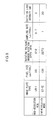
- Fig. 9 shows conditions in the high-resolution mode and conditions in the low-resolution mode in the radiographic image reading device 10 in accordance with the present exemplary embodiment. In the present exemplary embodiment of the radiographic image reading device 10, these conditions are memorized in advance in the HDD of the control section 20 and the resolution setting section 22, or the like.
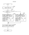
- Fig. 10 is a flowchart showing the flow of an example of the reading control processing that is executed by the control section 20 of the radiographic image reading device 10 in accordance with the present exemplary embodiment.
- the reading control processing illustrated in Fig. 10 is executed when radiographic image information is to be read from a storage phosphor sheet IP, in a case in which reading of the radiographic image information has been instructed or the like.
- the reading control processing illustrated in Fig. 10 is executed by the CPU of the control section 20 executing the program memorized in the ROM.
- step S100 the control section 20 acquires the resolution.
- the resolution is specified at the resolution setting section 22
- either the high-resolution mode or the low-resolution mode is acquired therefrom.
- the resolution is designated via the interface section 28 or the like, the resolution (the high-resolution mode or the low-resolution mode) is acquired on the basis of this designation.
- step S102 the control section 20 makes a determination as to whether or not the mode is the high-resolution mode.
- the control section 20 advances from step S102 to step S106.
- step S106 the control section 20 determines the scanning speed (a first scanning speed) and the excitation light intensity (a first intensity) of the low-resolution mode.
- the control section 20 determines a scanning speed of 1.0 ⁇ s/pixel and an excitation light intensity of 20 mW in the low-resolution mode.
- step S104 the control section 20 determines the scanning speed (a second scanning speed) and the excitation light intensity (a second intensity) of the high-resolution mode.
- the control section 20 determines a scanning speed of 0.7 ⁇ s/pixel and an excitation light intensity of 2.0 mW in the high-resolution mode.
- step S108 the control section 20 sets the determined scanning speed and excitation light intensity, after which the present reading control processing ends.
- the control section 20 instructs the motor driving circuit 26 the determined scanning speed, and the motor driving circuit 26 drives (rotates) the rotating polygon mirror 14 in accordance with this instruction.
- the control section 20 instructs the light source control section 24 the determined excitation light intensity, and the light source control section 24 controls light emissions from the light source 12 in accordance with this instruction.
- a high-resolution mode (with a pixel size of 25 ⁇ m/pixel) and a low-resolution mode (with a pixel size of 100 ⁇ m/pixel) are provided as modes for reading radiographic image information from storage phosphor sheets IP.
- the control section 20 makes the intensity of the excitation light smaller in the high-resolution mode than in a case of reading radiographic image information in the low-resolution mode.
- the control section 20 also makes the scanning speed slower in the high-resolution mode than in the case of reading radiographic image information in the low-resolution mode.
- the rotation speed of the rotating polygon mirror 14 is 812 RPM
- the scanning speed (reading speed) is 0.7 ⁇ s/pixel
- the intensity of the excitation light is 2.0 mW.
- the rotation speed of the rotating polygon mirror 14 is 2,273 RPM
- the scanning speed (reading speed) is 1.0 ⁇ s/pixel
- the intensity of the excitation light is 20 mW.
- the intensity of the excitation light is switched between the high-resolution mode and the low-resolution mode, and because the high-resolution mode has a smaller excitation light intensity than the low-resolution mode, scanning irregularities produced in the radiographic images may be suppressed.
- scanning irregularities in a radiographic image may be suppressed without the scanning irregularities being removed from the image data by image correction.
- scanning irregularities need not be removed from the image data by image correction, there is no risk of portions of a scanning target being mistakenly removed by image correction.
- the excitation light intensity in the high-resolution mode is set to 30% or less of the excitation light intensity in the low-resolution mode, the production of scanning irregularities can be appropriately suppressed in the low-resolution mode too.
- the excitation light intensity in the high-resolution mode is set to 2.0 mW, both the production of scanning irregularities may be appropriately suppressed and a high signal-to-noise ratio may be obtained.
- the pixel size is less than the excitation light beam diameter in the high-resolution mode, and the pixel size is greater than the excitation light beam diameter in the low-resolution mode. Further, the pixel size is 25 ⁇ m and the beam diameter is 30 ⁇ m in the high-resolution mode. Accordingly, both a high resolution in the high-resolution mode and low costs may be achieved.
- the reading control processing program is memorized in advance in the control section 20 of the radiographic image reading device 10.
- the program may be obtained and memorized from a recording medium such as a floppy disk, a Digital Versatile Disc (DVD), a magneto-optical disc, a Universal Serial Bus (USB) memory or the like, or from external equipment or the like.
- the reading control processing is implemented by software processing, but the reading control processing may also be implemented by hardware resources.
- the radiation of the present invention is not particularly limited by the present exemplary embodiment; X-rays, gamma rays and so forth may be employed.
Landscapes
- Physics & Mathematics (AREA)
- Health & Medical Sciences (AREA)
- Life Sciences & Earth Sciences (AREA)
- General Physics & Mathematics (AREA)
- High Energy & Nuclear Physics (AREA)
- Molecular Biology (AREA)
- Spectroscopy & Molecular Physics (AREA)
- Facsimile Scanning Arrangements (AREA)
- Conversion Of X-Rays Into Visible Images (AREA)
- Radiography Using Non-Light Waves (AREA)
- Mechanical Optical Scanning Systems (AREA)
Abstract
Description
- The present invention relates to a radiographic image reading device, a radiographic image reading program, and a radiographic image reading method.
- When radiation (X-rays, α rays, β rays, γ rays, ultraviolet rays, an electron beam or the like) is irradiated onto a storage phosphor (a photostimulable phosphor), a portion of the radiation energy is stored in the storage phosphor. Subsequently, when an excitation light such as a laser light or the like is illuminated onto the storage phosphor, the storage phosphor is photostimulated and luminesces in accordance with the stored energy.
- In general, radiographic image reading devices that employ storage phosphors are used for clinical applications, non-destructive testing in industry and the like. In a radiographic image reading device, image information of a radiographic image of an imaging subject, such as a weld or the like, is temporarily recorded in a sheet (an image plate IP, which is a storage phosphor sheet) that includes a storage phosphor layer. The storage phosphor sheet IP is scanned with excitation light, and photostimulated luminescence light that is produced is read photoelectrically.
- For example, Japanese Patent Application Laid-Open (JP-A) No.
2004-163792 - Meanwhile, there are calls for the elimination of irregularities (scanning irregularities) that arise in radiographic images.
JP-A No. 2010-239480 - With the technology recited in
JP-A No. 2010-239480 - The present invention has been made in view of the above circumstances and provides a radiographic image reading device, a radiographic image reading program, and a radiographic image reading method.
- According to an aspect of the invention, there is provided a radiographic image reading device which includes: reading means that photoelectrically read photostimulated luminescence light produced from a storage phosphor sheet illuminated with excitation light, the storage phosphor sheet, at which a radiographic image is stored, being scanned by scanning means using the excitation light; and control means that control the reading means to so as cause the reading means, in a case of reading at a first resolution, to read with excitation light at a first scanning speed and a first intensity and, in a case of reading at a second resolution that is a higher resolution than the first resolution, to read with excitation light at a second scanning speed that is slower than the first scanning speed and a second intensity that is smaller than the first intensity.
- In the radiographic image reading device according to the aspect of the present invention, a beam diameter of the excitation light at a surface of the storage phosphor sheet may be the same regardless of the resolution, a pixel size of the first resolution may be larger than the beam diameter of the excitation light, and a pixel size of the second resolution may be smaller than the beam diameter of the excitation light.
- In the radiographic image reading device according to the aspect of the present invention, it is preferable that a second intensity may be 2.0 mW or more at a surface of the storage phosphor sheet.
- In the radiographic image reading device according to the aspect of the present invention, it is preferable that a second intensity at a surface of the storage phosphor sheet may be 30% or less of the first intensity at the surface of the storage phosphor sheet.
- In the radiographic image reading device according to the aspect of the present invention, it is preferable that a beam diameter of the excitation light may be 30 µm, a preferable pixel size of the first resolution may be 100 µm, and a pixel size of the second resolution may be 25 µm.
- According to another aspect of the invention, there is provided a radiographic image reading program that causes a computer to function as the control means of the radiographic image reading device according to the aspect of the present invention.
- According to another aspect of the invention, there is provided a radiographic image reading method which includes, controlling, by controlling means, reading means that photoelectrically read photostimulated luminescence light produced from a storage phosphor sheet illuminated with excitation light, the storage phosphor sheet, at which a radiographic image is stored, being scanned by scanning means using the excitation light, so as to cause the reading means, in a case of reading at a first resolution, to read with excitation light at a first scanning speed and a first intensity and, in a case of reading at a second resolution that is a higher resolution than the first resolution, to read with excitation light at a second scanning speed that is slower than the first scanning speed and a second intensity that is smaller than the first intensity.
- According to the present invention, image quality can be raised and scanning irregularities can be reduced.
- Preferred embodiments of the present invention will be described in detail based on the following figures, wherein:
-
Fig. 1 is a vertical sectional diagram showing the schematic structure of a radiographicimage reading device 10, in accordance with a present exemplary embodiment, that reads image information of a radiographic image recorded at a storage phosphor sheet IP. -
Fig. 2A is a plan diagram showing an example of the structure of an excitation light scanning unit in accordance with the present exemplary embodiment. -
Fig. 2B is a side view showing the example of the structure of the excitation light scanning unit in accordance with the present exemplary embodiment. -
Fig. 3A is a descriptive view for describing scanning irregularities, which is a conceptual view illustrating scanning irregularities that are produced in a read radiographic image. -
Fig. 3B is a descriptive view for describing the scanning irregularities, which is a descriptive view showing image densities (QL values) in a sub-scanning direction of the radiographic image ofFig. 3A in which the scanning irregularities are produced. -
Fig. 4 is a schematic diagram of an example of principal structures for suppressing the production of scanning irregularities in the radiographic image reading device in accordance with the present invention. -
Fig. 5A is a graph showing an example of correspondences between intensities of excitation light and scanning irregularity intensities (QL values) in a high-resolution mode and a low-resolution mode. -
Fig. 5B is a table showing an example of the correspondence between the intensity of excitation light and scanning irregularities in the high-resolution mode. -
Fig. 5C is a table showing an example of the correspondence between the intensity of excitation light and scanning irregularities in the low-resolution mode. -
Fig. 6A is a descriptive diagram for describing a correspondence between a beam diameter of excitation light and a pixel size at the surface of a storage phosphor sheet IP, showing a case in which the excitation light beam diameter is larger than the pixel size. -
Fig. 6B is a descriptive diagram for describing the correspondence between the beam diameter of excitation light and the pixel size at the surface of the storage phosphor sheet IP, showing a case in which the excitation light beam diameter is smaller than the pixel size. -
Fig. 7A is a graph showing an example of a correspondence between the intensity of excitation light and the signal-to-noise ratio of a radiographic image in the high-resolution mode, showing an example of a correspondence with the excitation light intensity. -
Fig. 7B is a table showing the example of the correspondence between the intensity of excitation light and the signal-to-noise ratio of a radiographic image in the high-resolution mode, showing the example of the correspondence between the excitation light intensity and the signal-to-noise ratio. -
Fig. 8 is a graph showing an example of a correspondence between the excitation light beam diameter and resolvability in the high-resolution mode. -
Fig. 9 is a table showing conditions in the high-resolution mode and conditions in the low-resolution mode in the radiographic image reading device in accordance with the present exemplary embodiment. -
Fig. 10 is a flowchart showing the flow of an example of reading control processing that is executed by a control section of the radiographic image reading device in accordance with the present exemplary embodiment. - Herebelow, an example of a present exemplary embodiment is described with reference to the attached drawings.
- First, schematic structure of the radiographic image reading device according to the present exemplary embodiment is described.
Fig. 1 is a vertical sectional diagram showing the schematic structure of a radiographicimage reading device 10 that reads image information of a radiographic image recorded at a storage phosphor sheet IP (hereinafter referred to as "radiographic image information"). The radiographicimage reading device 10 according to the present exemplary embodiment may be, for example, a radiographic image reading device that reads radiographic image information recorded at storage phosphor sheets IP in a computed radiography (CR) system for industrial applications, or the like. - As shown in
Fig. 1 , atouch panel 32 is provided at an upper portion of acasing 30 that structures the exterior of the radiographicimage reading device 10. Thetouch panel 32 has the functions of an operation portion and a monitor. A plural number, for example, four, ofcassette loading portions 36a to 36d, at whichcassettes 34 can be mounted and removed, are provided below thetouch panel 32. - Each
cassette 34 includes arectangular case 40, which accommodates a storage phosphor sheet IP, and acover body 44, which is capable of opening and closing anopening portion 42 of thecase 40. - Support stands 46, on which the
cassettes 34 are placed, are provided in thecassette loading portions 36a to 36d.Shutter members 48 are also provided in thecassette loading portions 36a to 36d, to be capable of opening and closing. Eachshutter member 48 is for shielding the interior of thecasing 30 from light. Cassette position fixing mechanisms (not shown in the drawings) and cover body opening-and-closing mechanisms (not shown in the drawings) are incorporated in thecassette loading portions 36a to 36d. Each cassette position fixing mechanism fixes the position of thecassette 34, and each cover body opening-and-closing mechanism opens and closes thecover body 44 of thecassette 34. - An ascending-and-descending sheet-feeding
unit 50 is installed at the interior of thecassette loading portions 36a to 36d. The ascending-and-descending sheet-feedingunit 50 is disposed in arbitrary correspondence with one of thecassette loading portions 36a to 36d. The ascending-and-descending sheet-feedingunit 50 has functions for extracting the storage phosphor sheet IP from thearbitrary cassette 34 and returning the storage phosphor sheet IP into thecassette 34 after the storage phosphor sheet IP has been read and erased. The ascending-and-descending sheet-feedingunit 50 is provided with a sheet body sheet-feedingmechanism 52 and a raising-and-loweringmechanism 54. The sheet body sheet-feedingmechanism 52 includes rollers for conveying the storage phosphor sheets IP one sheet at a time, and the raising-and-loweringmechanism 54 is capable of raising and lowering the sheet body sheet-feedingmechanism 52 in an up-and-down direction (the direction of arrow A). - A
main conveyance path 60 for conveying each storage phosphor sheet IP is linked to the sheet body sheet-feedingmechanism 52 of the ascending-and-descending sheet-feedingunit 50. Themain conveyance path 60 extends downward from the ascending-and-descending sheet-feedingunit 50, then curves at a lower portion of thecasing 30, and reaches areading conveyance path 70 that extends in the horizontal direction. Afirst roller pair 80 and asecond roller pair 82 that structure the readingconveyance path 70 nip the storage phosphor sheet IP and convey the storage phosphor sheet IP in the direction of arrow Y for sub-scanning. Thefirst roller pair 80 andsecond roller pair 82 used in the present exemplary embodiment are rollers whose external periphery faces are fabricated of rubber. - The reading
conveyance path 70 curves and extends upward, and connects with awithdrawal conveyance path 94 that extends in the horizontal direction. One end of anerasure conveyance path 96 connects between the readingconveyance path 70 and thewithdrawal conveyance path 94. The other end of theerasure conveyance path 96 connects with themain conveyance path 60, and theerasure conveyance path 96 supplies a storage phosphor sheet IP conveyed from thewithdrawal conveyance path 94 to themain conveyance path 60. - An excitation
light scanning unit 64 and anupper reading unit 66 are disposed at an upper portion of an inner periphery side of the readingconveyance path 70 that curves upward. -
Fig. 2A and Fig. 2B are structural diagrams showing an example of the structure of the excitationlight scanning unit 64.Fig. 2A shows a plan view of the excitationlight scanning unit 64 andFig. 2B shows a side view of the excitationlight scanning unit 64. - As shown in
Fig. 2A and Fig. 2B , the excitationlight scanning unit 64 is provided with alight source 12, and a diverginglens system 13 for converting excitation light L, which is a laser beam emitted from thelight source 12, to divergent light. The excitation light L is made divergent by the diverginglens system 13. Thelight source 12 may be, for example, a laser diode or the like. - The excitation
light scanning unit 64 is provided with arotating polygon mirror 14, afirst lens 16, asecond lens 17, and a reflectingmirror 18. Therotating polygon mirror 14 is for reflectively deflecting the excitation light L diverged by the diverginglens system 13 toward a surface (a scanning face) of the storage phosphor sheet IP. Thefirst lens 16 andsecond lens 17 are disposed subsequent to therotating polygon mirror 14 and are included in a scanning focusing optical system that focuses the excitation light L on the storage phosphor sheet IP. The reflectingmirror 18 is for reflecting the excitation light L toward the storage phosphor sheet IP. - According to the excitation
light scanning unit 64, the excitation light L emitted from thelight source 12 is temporarily made divergent by the diverginglens system 13, and then reflected by deflecting faces provided at outer periphery faces of therotating polygon mirror 14. - The excitation light L reflected by the deflecting faces of the
rotating polygon mirror 14 passes through thefirst lens 16 andsecond lens 17, is reflected by the reflectingmirror 18 and focused on the storage phosphor sheet IP, and exposes the storage phosphor sheet IP by scanning in a main scanning direction. Meanwhile, the storage phosphor sheet IP is being driven in the sub-scanning direction, which is orthogonal to the main scanning direction in which the excitation light L is scanning, by a driving unit (seeFig. 1 ). Thus, the surface of the storage phosphor sheet IP is scanned with the excitation light L. Photostimulated luminescence light, containing the radiographic image information, is outputted from the storage phosphor sheet IP on which the excitation light L is illuminated. - The
upper reading unit 66 is provided with a condensingguide 84 and aphotoelectric converter 86. The condensingguide 84 includes a transparent member such as an acrylic plate or the like, of which an incidence face at a lower end portion thereof is disposed in a vicinity between thefirst roller pair 80 and thesecond roller pair 82. Thephotoelectric converter 86 includes a photomultiplier or the like that is connected to an emission face at an upper end portion of the condensingguide 84. - A condensing
mirror 88 is disposed close to the incidence face of the condensingguide 84. The condensingmirror 88 is for efficiently directing the photostimulated luminescence light into the incidence face. Thephotoelectric converter 86 converts the photostimulated luminescence light that has been guided through the condensingguide 84 to electronic signals. - In the present exemplary embodiment, as shown in
Fig. 1 , portions of thephotoelectric converter 86 other than a light incidence portion (a photoelectric surface) are covered with amagnetic shield member 90. As an example, a member with high magnetic permeability is employed as themagnetic shield member 90. Specifically, permalloy, an oriented electrical steel plate, an iron plate (pure iron) or the like may be used, or an alternative material may be used. Here, permalloy is most excellently employed as themagnetic shield member 90. - A
control circuit 120 and anerasure unit 122 are disposed between thewithdrawal conveyance path 94 and theerasure conveyance path 96. Thecontrol circuit 120 controls the radiographicimage reading device 10 as a whole. Theerasure unit 122 eliminates radiation energy remaining in a storage phosphor sheet IP from which the radiographic image information has been read. Theerasure unit 122 accommodates a plural number oferasure light sources 126 in acase 124. Eacherasure light source 126 is formed of a cold-cathode fluorescent tube or the like. - Now, a flow of reading operations by the radiographic
image reading device 10 to read a radiographic image from a storage phosphor sheet IP is described. - In the present exemplary embodiment, the conveyance direction in the radiographic
image reading device 10 is the sub-scanning direction (the direction of arrow L1 inFig. 3A ), corresponding to the longest direction of a storage phosphor sheet IP (i.e., of a radiographic image recorded at the storage phosphor sheet IP), and the direction orthogonal to the longest direction of the storage phosphor sheet IP (the direction of arrow W1 inFig. 3A ) is the main scanning direction. Each storage phosphor sheet IP is accommodated in thecassette 34 facing to the lower side, and thecassette 34 is loaded in thecassette loading portions 36a to 36d (seeFig. 1 ). - The
cassette 34 loaded in thecassette loading portions 36a to 36d is fixed in position by the mechanism that fixes the position of thecassette 34, after which thecover body 44 of thecassette 34 is opened and the storage phosphor sheet IP is sheet-fed from thecassette 34 by the ascending-and-descending sheet-feedingunit 50. The sheet-fed storage phosphor sheet IP is conveyed by themain conveyance path 60 and is provided to thereading conveyance path 70. - In the
reading conveyance path 70, the storage phosphor sheet IP is nipped by the first and second roller pairs 80 and 82 and is conveyed for sub-scanning in the direction of arrow Y. - Meanwhile, the excitation
light scanning unit 64 disposed above the readingconveyance path 70 deflects the excitation light L emitted from thelight source 12 in the main scanning direction with therotating polygon mirror 14, thus scanning a storage phosphor layer (not shown in the drawings) of the storage phosphor sheet IP. The storage phosphor layer of the storage phosphor sheet IP illuminated with the excitation light L outputs photostimulated luminescence light containing radiographic image information. - The photostimulated luminescence light outputted from the storage phosphor layer of the storage phosphor sheet IP is incident on the incidence surface of the condensing
guide 84 provided at theupper reading unit 66 directly, and is reflected by the condensingmirror 88 and made incident on the incidence surface. Hence, the light is directed through the emission surface of the condensingguide 84 to thephotoelectric converter 86 and is converted to electronic signals. - The electronic signals relating to the radiographic image information that are obtained by the
photoelectric converter 86 are transferred to thecontrol circuit 120 or, via a wired or wireless communications circuit or the like, to external equipment or the like. - The storage phosphor sheet IP for which reading has been completed is temporarily conveyed from the reading
conveyance path 70 to thewithdrawal conveyance path 94, and then provided to theerasure conveyance path 96. While a storage phosphor sheet IP for which reading has been completed is being temporarily conveyed to thewithdrawal conveyance path 94, another storage phosphor sheet IP may be provided to thereading conveyance path 70. Thus, reading processes may be carried out concurrently. - An erasure light Q from the
erasure light sources 126 provided in theerasure unit 122 is illuminated at the storage phosphor layer of the storage phosphor sheet IP provided to theerasure conveyance path 96. Thus, radiographic image information remaining in the storage phosphor layer is erased. The erased storage phosphor sheet IP is conveyed via themain conveyance path 60 to the raising-and-loweringmechanism 54, and is then returned to thepredetermined cassette 34. - There may be cases in which irregularities caused by density variations (scanning irregularities) arise in the radiographic image according to the radiographic image information recorded in the storage phosphor sheet IP.
Fig. 3A and Fig. 3B show descriptive diagrams for describing scanning irregularities.Fig. 3A is a conceptual view illustrating scanning irregularities that are produced in a read radiographic image.Fig. 3B is a descriptive view showing image densities (QL values) in the sub-scanning direction of the radiographic image ofFig. 3A in which scanning irregularities are produced. As shown inFig. 3A and Fig. 3B , the scanning irregularities are produced along the main scanning direction of the radiographic image, and image densities (QL values) are higher at the scanning irregularities. - Causes for the occurrence of scanning irregularities include: variations in the rotation speeds of motors (not shown in the drawings) that are used for sub-scanning conveyance of the storage phosphor sheets IP; eccentricity of the roller pairs 80 and 82 and the like that are used for conveying the storage phosphor sheets IP; load variations when a storage phosphor sheet IP is fed to the roller pairs 80 and 82; load variations when a storage phosphor sheet IP leaves the roller pairs 80 and 82; and the like.
- There are strict requirements relating to scanning irregularities occurring in radiographic images because-for example, in industrial CR-images are enlarged and reduced on a monitor, contrasts are maximized, and so forth. On the other hand, in a case in which scanning irregularities are removed from image data by image correction, there is a risk that portions of a scanning target may be mistakenly removed. For example, in a case in which a portion of the scanning target is a welding defect or the like, in accordance with the defect having a linear shape, the defect may be corrected as a scanning irregularity. Thus, the defect may be removed from the radiographic image that is ultimately obtained.
- Accordingly, in the radiographic
image reading device 10 according to the present exemplary embodiment, the production of scanning irregularities is suppressed while the radiographic image information is being read. Specifically, in the radiographicimage reading device 10, the production of scanning irregularities is suppressed by thecontrol circuit 120 controlling driving of the excitationlight scanning unit 64 and controlling the power of the excitation light.Fig. 4 is a schematic diagram of an example of principal structures for suppressing the production of scanning irregularities in the radiographicimage reading device 10 in accordance with the present invention. - As shown in
Fig. 4 , thecontrol circuit 120 is provided with acontrol section 20, aresolution setting section 22, a lightsource control section 24, amotor driving circuit 26 and aninterface section 28. Thecontrol section 20,resolution setting section 22, lightsource control section 24,motor driving circuit 26 andinterface section 28 are connected by abus 29 to enable exchanges of various kinds of information. - The
control section 20 is structured by a microcomputer and is provided with a central processing unit (CPU), a read-only memory (ROM), a random access memory (RAM) and a hard disk drive (HDD). In thecontrol section 20 according to the present exemplary embodiment, the CPU executes reading control processing, which is described in detail below, by executing a program memorized in the ROM. Note that thecontrol section 20 is not limited to the structure shown inFig. 4 and may be realized by, for example, an application-specific integrated circuit (ASIC), a programmable logic device or the like. - The
resolution setting section 22 specifies a resolution for reading a radiographic image. In the radiographicimage reading device 10 according to the present exemplary embodiment, two modes are provided as resolutions for reading the radiographic image-a high-resolution mode and a low-resolution mode. The high-resolution mode has a higher resolution than the low-resolution mode, specifically, a pixel size of 25 µm/pixel. The low-resolution mode has a lower resolution than the high-resolution mode, specifically, a pixel size of 100 µm/pixel. Thus, the pixel size is larger in the low-resolution mode than in the high-resolution mode. The meaning of the term "pixel size" includes a value, for both the main scanning direction and the sub-scanning direction, for which a scanning width of the storage phosphor sheet IP is divided by a number of pixels. In the radiographicimage reading device 10 according to the present exemplary embodiment, a reading speed is slower in the high-resolution mode than in the low-resolution mode. - In a case in which a user designates a resolution via the
touch panel 32 provided at the upper portion of the radiographicimage reading device 10, or theinterface section 28 or the like, the designated resolution (the high-resolution mode or the low-resolution mode) is specified at theresolution setting section 22. - The light
source control section 24 has a function for controlling thelight source 12 of the excitationlight scanning unit 64. In the present exemplary embodiment, the lightsource control section 24 is controlled by thecontrol section 20, and thus the intensity (laser power) of the excitation light from thelight source 12 is controlled. A method of control of the intensity of the excitation light is not particularly limited; for example, in a case in which thelight source 12 is a laser diode, the current value of a driving current may be controlled. - The
motor driving circuit 26 has a function for driving (rotating) therotating polygon mirror 14 of the excitationlight scanning unit 64. In the present exemplary embodiment, themotor driving circuit 26 is controlled by thecontrol section 20, and thus the rotation speed of therotating polygon mirror 14 is controlled. In the radiographicimage reading device 10 according to the present exemplary embodiment, the scanning speed at which the surface of the storage phosphor sheet IP is scanned in the sub-scanning direction is controlled, and the reading speed (sampling rate) of the radiographic image is controlled. Specifically, thecontrol section 20 controls the rotation speed of therotating polygon mirror 14. In the present exemplary embodiment, the rotation speed of therotating polygon mirror 14 is denoted as a rotation frequency (RPM). The greater the rotation frequency, the faster the rotation speed and the faster the scanning speed. On the other hand, the lower the rotation frequency, the slower the rotation speed and the slower the scanning speed. Theinterface section 28 is an interface that exchanges information with external equipment. - The production of scanning irregularities in the high-resolution mode and the production of scanning irregularities in the low-resolution mode are now described.
Fig. 5A to Fig. 5C show examples of correspondences between the intensity of excitation light and scanning irregularity intensities (QL values) in the high-resolution mode and the low-resolution mode.Fig. 5A is a graph showing an example of correspondences between intensities of excitation light and scanning irregularity intensities (QL values) in a high-resolution mode and a low-resolution mode.Fig. 5B is a table showing an example of the correspondence between the intensity of excitation light and scanning irregularities in the high-resolution mode, andFig. 5C is a table showing an example of the correspondence between the intensity of excitation light and scanning irregularities in the low-resolution mode. - In the storage phosphor sheet IP used in the present exemplary embodiment, the photostimulable phosphor that is used is BaFX:Eu2+ (X = Br, I). As a specific example in a case of the high-resolution mode, Fujifilm Imaging Plate Industrial UR-1, fabricated by Fujifilm Corporation, is used. As a specific example in a case of the low-resolution mode, Fujifilm Imaging Plate Industrial ST-VI, fabricated by Fujifilm Corporation, is used.
- Reading conditions in the high-resolution mode are: pixel size, 25 µm/pixel; scanning speed (reading speed), 0.7 µs/pixel; excitation light wavelength, 660 nm; and half-amplitude beam diameter of the excitation light, 30 µm. Reading conditions in the low-resolution mode are: pixel size, 100 µm/pixel; scanning speed (reading speed), 1.0 µs/pixel; excitation light wavelength, 660 nm; and half-amplitude beam diameter of the excitation light, 30 µm. Thus, in the radiographic
image reading device 10 according to the present exemplary embodiment, the wavelength and beam diameter of the excitation light are the same irrespective of the high-resolution mode or the low-resolution mode. In the present exemplary embodiment, "the beam diameter" that is referred to is the beam diameter defined by the half-amplitude of the excitation light at the surface of the storage phosphor sheet IP. - As shown in
Fig. 5A to Fig. 5C , the stronger the intensity of the excitation light in either the high-resolution mode or the low-resolution mode, the greater the intensities (QL values) of the scanning irregularities, and the smaller the intensity of the excitation light, the smaller the intensities (QL values) of the scanning irregularities. Correspondences between excitation light intensities and scanning irregularity intensities are considered to be particular properties of the storage phosphor sheets IP. In a case in which the excitation light intensities are the same, the intensities (QL values) of the scanning irregularities are smaller in the low-resolution mode than in the high-resolution mode. - As shown in
Fig. 5A to Fig. 5C , given excitation light intensities that are the same, there is a tendency for the scanning irregularities to be more visible in a case in which the excitation light beam diameter is larger than the pixel size than in a case in which the excitation light beam diameter is smaller than the pixel size. Taking this factor as an example, the following can be said about scanning irregularities. - In the radiographic
image reading device 10 according to the present exemplary embodiment, the excitation light illuminated from the excitationlight scanning unit 64 is scanned in accordance with the pixels to be read.Fig. 6A and Fig. 6B are descriptive diagrams for describing a correspondence between the excitation light beam diameter and the pixel size at the surface of the storage phosphor sheet IP.Fig. 6A shows a case in which the excitation light beam diameter is larger than the pixel size, andFig. 6B shows a case in which the excitation light beam diameter is smaller than the pixel size. - As shown in
Fig. 6A , in the case in which the excitation light beam diameter is larger than the pixel size, the excitation light illuminated when line (pixel row) n is being read and the excitation light illuminated when line (pixel row) n+1 is being read overlap on the surface of the storage phosphor sheet IP, and a scanning irregularity is likely to arise. In contrast, as shown inFig. 6B , in the case in which the excitation light beam diameter is smaller than the pixel size, the excitation light illuminated when line (pixel row) n is being read and the excitation light illuminated when line (pixel row) n+1 is being read do not overlap on the surface of the storage phosphor sheet IP. - In the case in which the excitation light beam diameter is larger than the pixel size, as shown in
Fig. 6A , the excitation light is illuminated twice at the overlap portion on the storage phosphor sheet IP, as a result of which a scanning irregularity is more likely to be visible than in the case in which the excitation light beam diameter is smaller than the pixel size. - In general, if the intensity (QL value) of a scanning irregularity is less than 10, even if the scanning irregularity is produced in the radiographic image, the scanning irregularity is hard to see. Thus, if the intensity of the excitation light is calculated from the graph shown in
Fig. 5A for cases in which the intensity (QL value) of scanning irregularities is 10, which has little effect on the interpretation of the subject image, 9.7 mW is obtained for the high-resolution mode and 32 mW is obtained for the low-resolution mode. Thus, the excitation light intensity in the high-resolution mode is about 30% of the excitation light intensity in the low-resolution mode. - Therefore, in a case in which the scanning irregularity intensity (QL value) is, for example, 10 or less or the like as described above and scanning irregularities are no problem in the low-resolution mode, the production of scanning irregularities in the high-resolution mode may be suppressed if the excitation light intensity in the high-resolution mode is 30% or less of the excitation light intensity in the low-resolution mode.
- In the radiographic
image reading device 10 according to the present exemplary embodiment, the production of scanning irregularities may be suppressed by thecontrol section 20 controlling excitation light intensities in the high-resolution mode and the low-resolution mode in this manner. According toFig. 5A to Fig. 5C , it is preferable with regard to scanning irregularities if the excitation light intensity is 2.0 W or less. - On the other hand, the higher the excitation light intensity, the higher the signal-to-noise ratio and the higher the image quality of the radiographic image.
Fig. 7A and Fig. 7B show an example of a correspondence between the intensity of excitation light and the signal-to-noise ratio in the high-resolution mode.Fig. 7A is a graph showing an example of the correspondence with the excitation light intensity, andFig. 7B is a table showing the example of the correspondence between the excitation light intensity and the signal-to-noise ratio. InFig. 7A and Fig. 7B , the conditions of the high-resolution mode are the same as those mentioned above. - For an image quality complying with ISO 17636-2 (for welding), it is preferable if the signal-to-noise ratio of a radiographic image used for checking defects in a weld is 80 or more. When manufacturing variations and the like are considered, it is more preferable for the signal-to-noise ratio of the radiographic image to be 100 or more.
- It can be seen from
Fig. 7A and Fig. 7B that for the signal-to noise ratio of a radiographic image to be 100 or more, it is required for the excitation light intensity to be 2.0 mW or more. In the low-resolution mode too, if the excitation light intensity is 2.0 mW or more, the signal-to-noise ratio of the radiographic image is 100 or more, the same as in the high-resolution mode. - In addition to the signal-to-noise ratio increasing as a result of the excitation light intensity being increased, as described above (see
Fig. 5A ), the effect of an increase in the intensities of scanning irregularities also increases. Therefore, fromFig. 7A and Fig. 7B , it is preferable if an upper limit of the excitation light intensity is 9.7 mW or less. - In the high-resolution mode it is preferable that the excitation light beam diameter is smaller, in order to improve resolvability. However, to reduce the beam diameter, it is necessary to increase the number of lenses included in the scanning focusing optical system of the excitation
light scanning unit 64 and make other alterations, which leads to an increase in costs. Accordingly, in the radiographicimage reading device 10 according to the present exemplary embodiment, to keep costs down, the excitation light beam diameter is larger than the pixel size in the high-resolution mode. Thus, by the beam diameter size being set in accordance with resolvability in the high-resolution mode, both a high resolution and low costs may be achieved. -
Fig. 8 shows an example of a correspondence between the excitation light beam diameter and resolvability in the high-resolution mode. InFig. 8 , of the conditions in the high-resolution mode, the excitation light intensity is set to 2.0 mW, the beam diameter is set arbitrarily, and other conditions are the same as mentioned above. - In general, it is required that resolvability for industrial CR is obtained by measuring the ability to resolve two wires defined by EN462-5, referred to as a duplex wire. In a case of checking welded portions, a resolvability at DD13 (a condition in which 50 µm wires are spaced by 50 µm) is required to be 20% or more. According to
Fig. 8 , in the high-resolution mode with a pixel size of 25 µm, a resolvability at the required 20% or above may be obtained if the beam diameter is 36 µm or less. Given this, in the radiographicimage reading device 10 according to the present exemplary embodiment, the beam diameter is set to 30 µm regardless of the resolution (mode) and the pixel size in the high-resolution mode is set to 25 µm. - According to the above descriptions, the radiographic
image reading device 10 according to the present exemplary embodiment suppresses the production of scanning irregularities by thecontrol section 20 performing reading control processing to make the excitation light intensity smaller in the high-resolution mode than in the low-resolution mode.Fig. 9 shows conditions in the high-resolution mode and conditions in the low-resolution mode in the radiographicimage reading device 10 in accordance with the present exemplary embodiment. In the present exemplary embodiment of the radiographicimage reading device 10, these conditions are memorized in advance in the HDD of thecontrol section 20 and theresolution setting section 22, or the like. -
Fig. 10 is a flowchart showing the flow of an example of the reading control processing that is executed by thecontrol section 20 of the radiographicimage reading device 10 in accordance with the present exemplary embodiment. The reading control processing illustrated inFig. 10 is executed when radiographic image information is to be read from a storage phosphor sheet IP, in a case in which reading of the radiographic image information has been instructed or the like. The reading control processing illustrated inFig. 10 is executed by the CPU of thecontrol section 20 executing the program memorized in the ROM. - In step S100, the
control section 20 acquires the resolution. In a case in which the resolution is specified at theresolution setting section 22, either the high-resolution mode or the low-resolution mode is acquired therefrom. In a case in which the resolution is designated via theinterface section 28 or the like, the resolution (the high-resolution mode or the low-resolution mode) is acquired on the basis of this designation. - Then, in step S102, the
control section 20 makes a determination as to whether or not the mode is the high-resolution mode. In a case of the low-resolution mode, thecontrol section 20 advances from step S102 to step S106. In step S106, thecontrol section 20 determines the scanning speed (a first scanning speed) and the excitation light intensity (a first intensity) of the low-resolution mode. As illustrated inFig. 9 , thecontrol section 20 according to the present exemplary embodiment determines a scanning speed of 1.0 µs/pixel and an excitation light intensity of 20 mW in the low-resolution mode. - On the other hand, in a case of the high-resolution mode, the
control section 20 advances from step S102 to step S104. In step S104, thecontrol section 20 determines the scanning speed (a second scanning speed) and the excitation light intensity (a second intensity) of the high-resolution mode. As illustrated inFig. 9 , thecontrol section 20 according to the present exemplary embodiment determines a scanning speed of 0.7 µs/pixel and an excitation light intensity of 2.0 mW in the high-resolution mode. In other words, in a case of the high-resolution mode, a slower scanning speed is determined than in the low-resolution mode (second scanning speed < first scanning speed), and in the case of the high-resolution mode, a smaller excitation light intensity is determined than in the low-resolution mode (second intensity < first intensity). - After step S104 and step S106, in step S108, the
control section 20 sets the determined scanning speed and excitation light intensity, after which the present reading control processing ends. Thecontrol section 20 instructs themotor driving circuit 26 the determined scanning speed, and themotor driving circuit 26 drives (rotates) therotating polygon mirror 14 in accordance with this instruction. Thecontrol section 20 instructs the lightsource control section 24 the determined excitation light intensity, and the lightsource control section 24 controls light emissions from thelight source 12 in accordance with this instruction. - As described hereabove, in the radiographic
image reading device 10 according to the present exemplary embodiment, a high-resolution mode (with a pixel size of 25 µm/pixel) and a low-resolution mode (with a pixel size of 100 µm/pixel) are provided as modes for reading radiographic image information from storage phosphor sheets IP. Thecontrol section 20 makes the intensity of the excitation light smaller in the high-resolution mode than in a case of reading radiographic image information in the low-resolution mode. Thecontrol section 20 also makes the scanning speed slower in the high-resolution mode than in the case of reading radiographic image information in the low-resolution mode. As a specific example, in the high-resolution mode, the rotation speed of therotating polygon mirror 14 is 812 RPM, the scanning speed (reading speed) is 0.7 µs/pixel, and the intensity of the excitation light is 2.0 mW. Meanwhile, in the low-resolution mode, the rotation speed of therotating polygon mirror 14 is 2,273 RPM, the scanning speed (reading speed) is 1.0 µs/pixel, and the intensity of the excitation light is 20 mW. - Thus, in the radiographic
image reading device 10 according to the present exemplary embodiment, the intensity of the excitation light is switched between the high-resolution mode and the low-resolution mode, and because the high-resolution mode has a smaller excitation light intensity than the low-resolution mode, scanning irregularities produced in the radiographic images may be suppressed. - Thus, according to the radiographic
image reading device 10 of the present exemplary embodiment, scanning irregularities in a radiographic image may be suppressed without the scanning irregularities being removed from the image data by image correction. According to the radiographicimage reading device 10 of the present exemplary embodiment, because scanning irregularities need not be removed from the image data by image correction, there is no risk of portions of a scanning target being mistakenly removed by image correction. - In the radiographic
image reading device 10 according to the present exemplary embodiment, because the excitation light intensity in the high-resolution mode is set to 30% or less of the excitation light intensity in the low-resolution mode, the production of scanning irregularities can be appropriately suppressed in the low-resolution mode too. - In the radiographic
image reading device 10 according to the present exemplary embodiment, because the excitation light intensity in the high-resolution mode is set to 2.0 mW, both the production of scanning irregularities may be appropriately suppressed and a high signal-to-noise ratio may be obtained. - In the radiographic
image reading device 10 according to the present exemplary embodiment, the pixel size is less than the excitation light beam diameter in the high-resolution mode, and the pixel size is greater than the excitation light beam diameter in the low-resolution mode. Further, the pixel size is 25 µm and the beam diameter is 30 µm in the high-resolution mode. Accordingly, both a high resolution in the high-resolution mode and low costs may be achieved. - In the exemplary embodiment described above, a case is described in which the reading control processing program is memorized in advance in the
control section 20 of the radiographicimage reading device 10. However, the program may be obtained and memorized from a recording medium such as a floppy disk, a Digital Versatile Disc (DVD), a magneto-optical disc, a Universal Serial Bus (USB) memory or the like, or from external equipment or the like. In the present exemplary embodiment, the reading control processing is implemented by software processing, but the reading control processing may also be implemented by hardware resources. - The radiation of the present invention is not particularly limited by the present exemplary embodiment; X-rays, gamma rays and so forth may be employed.
- Structures, operations and the like of the radiographic
image reading device 10, the excitationlight scanning unit 64, theupper reading unit 66, thecontrol circuit 120 and the like described in the present exemplary embodiment are examples and it will it clear that these may be modified in accordance with conditions within a scope not departing from the spirit of the present invention. - Embodiments of the present invention are described above, but the present invention is not limited to the embodiments as will be clear to those skilled in the art.
Claims (7)
- A radiographic image reading device (10), comprising:reading means (66) that photoelectrically reads photostimulated luminescence light produced from a storage phosphor sheet (IP) illuminated with excitation light, the storage phosphor sheet, at which a radiographic image is stored, being scanned by scanning means (64) using the excitation light; andcontrol means (20) that controls the reading means so as to cause the reading means, in a case of reading at a first resolution, to read with excitation light at a first scanning speed and a first intensity and, in a case of reading at a second resolution that is a higher resolution than the first resolution, to read with excitation light at a second scanning speed that is slower than the first scanning speed and a second intensity that is smaller than the first intensity.
- The radiographic image reading device according to claim 1, wherein a beam diameter of the excitation light at a surface of the storage phosphor sheet is the same regardless of the resolution, a pixel size of the first resolution is larger than the beam diameter of the excitation light, and a pixel size of the second resolution is smaller than the beam diameter of the excitation light.
- The radiographic image reading device according to claim 1 or 2, wherein the second intensity is 2.0 mW or more at a surface of the storage phosphor sheet.
- The radiographic image reading device according to any one of claims 1 to 3, wherein the second intensity at a surface of the storage phosphor sheet is 30% or less of the first intensity at the surface of the storage phosphor sheet.
- The radiographic image reading device according to any one of claims 1 to 4, wherein a beam diameter of the excitation light is 30 µm, a pixel size of the first resolution is 100 µm, and a pixel size of the second resolution is 25 µm.
- A radiographic image reading program causing a computer to function as the control means of the radiographic image reading device according to any one of claims 1 to 5.
- A radiographic image reading method, comprising:controlling, by control means (20), reading means (66) that photoelectrically reads photostimulated luminescence light produced from a storage phosphor sheet illuminated with excitation light, the storage phosphor sheet (IP), at which a radiographic image is stored, being scanned by scanning means (64) using the excitation light, so as to cause the reading means, in a case of reading at a first resolution, to read with excitation light at a first scanning speed and a first intensity and, in a case of reading at a second resolution that is a higher resolution than the first resolution, to read with excitation light at a second scanning speed that is slower than the first scanning speed and a second intensity that is smaller than the first intensity.
Applications Claiming Priority (1)
| Application Number | Priority Date | Filing Date | Title |
|---|---|---|---|
| JP2013205196A JP5921511B2 (en) | 2013-09-30 | 2013-09-30 | Radiation image reading apparatus, radiation image reading program, and radiation image reading method |
Publications (1)
| Publication Number | Publication Date |
|---|---|
| EP2853924A1 true EP2853924A1 (en) | 2015-04-01 |
Family
ID=51178763
Family Applications (1)
| Application Number | Title | Priority Date | Filing Date |
|---|---|---|---|
| EP14177079.2A Withdrawn EP2853924A1 (en) | 2013-09-30 | 2014-07-15 | Radiographic image reading device, radiographic image reading program, and radiographic image reading method |
Country Status (3)
| Country | Link |
|---|---|
| US (1) | US9310492B2 (en) |
| EP (1) | EP2853924A1 (en) |
| JP (1) | JP5921511B2 (en) |
Citations (4)
| Publication number | Priority date | Publication date | Assignee | Title |
|---|---|---|---|---|
| EP0777148A1 (en) * | 1995-12-01 | 1997-06-04 | Fuji Photo Film Co., Ltd. | Radiation image read-out apparatus |
| JP2004163792A (en) | 2002-11-15 | 2004-06-10 | Fuji Photo Film Co Ltd | Radiation image reader |
| GB2431536A (en) * | 2005-10-18 | 2007-04-25 | Intense Ltd | Linear scanning head for computed radiography |
| JP2010239480A (en) | 2009-03-31 | 2010-10-21 | Fujifilm Corp | Image correction method and image correction apparatus |
Family Cites Families (19)
| Publication number | Priority date | Publication date | Assignee | Title |
|---|---|---|---|---|
| JPH0391734A (en) * | 1989-09-04 | 1991-04-17 | Eastman Kodatsuku Japan Kk | Radiograph reader |
| DE69213948T2 (en) * | 1992-11-25 | 1997-04-03 | Agfa Gevaert Nv | Process for reproducing a radiation image |
| JPH0764218A (en) * | 1993-08-31 | 1995-03-10 | Fujitsu Ltd | Radiation image reader |
| US6343142B1 (en) * | 1994-05-20 | 2002-01-29 | Fuji Photo Film Co., Ltd. | Image analyzing apparatus |
| US6314198B1 (en) * | 1996-09-25 | 2001-11-06 | Canon Kabushiki Kaisha | Radiographic, digital image processing system |
| US6365909B1 (en) * | 1997-11-10 | 2002-04-02 | Konica Corporation | Radiographic image reading apparatus |
| JP4138199B2 (en) * | 1999-03-23 | 2008-08-20 | 富士フイルム株式会社 | Image information reading method and apparatus |
| US6580525B1 (en) * | 1999-03-23 | 2003-06-17 | Fuji Photo Film Co., Ltd. | Method of and system reading out image signal |
| US6437359B1 (en) * | 1999-11-19 | 2002-08-20 | Eastman Kodak Company | CR reader with vertical scanning |
| US6696698B2 (en) * | 2000-06-29 | 2004-02-24 | Essex Electro Engineers, Inc. | Method and apparatus for radiographic imaging |
| JP4219576B2 (en) * | 2001-06-06 | 2009-02-04 | 富士フイルム株式会社 | Radiation image reading method and apparatus |
| US6969861B2 (en) * | 2001-10-02 | 2005-11-29 | Konica Corporation | Cassette for radiographic imaging, radiographic image reading apparatus and radiographic image reading method |
| US20050008262A1 (en) * | 2003-06-03 | 2005-01-13 | Konica Minolta Medical & Graphic, Inc. | Medical image system, and medical image processing method |
| US7148501B1 (en) * | 2005-12-28 | 2006-12-12 | Eastman Kodak Company | Storage phosphor reader having frame vibration isolation and frame locking |
| US7446331B2 (en) * | 2006-08-21 | 2008-11-04 | Carestream Health, Inc. | Apparatus for scanning stimulable phosphor medium |
| US20090039288A1 (en) * | 2006-12-18 | 2009-02-12 | Kulpinski Robert W | Single sided dual scanning for computed radiography |
| US7622730B2 (en) * | 2006-12-18 | 2009-11-24 | Carestream Health, Inc. | Single sided dual scanning for computed radiography |
| US7504648B2 (en) * | 2007-04-27 | 2009-03-17 | Carestream Health, Inc. | Method and apparatus for determining focus of a scanning system |
| KR20120079333A (en) * | 2011-01-04 | 2012-07-12 | 삼성전자주식회사 | Image reading apparatus and controlling method thereof |
-
2013
- 2013-09-30 JP JP2013205196A patent/JP5921511B2/en active Active
-
2014
- 2014-07-15 EP EP14177079.2A patent/EP2853924A1/en not_active Withdrawn
- 2014-07-25 US US14/340,834 patent/US9310492B2/en active Active
Patent Citations (4)
| Publication number | Priority date | Publication date | Assignee | Title |
|---|---|---|---|---|
| EP0777148A1 (en) * | 1995-12-01 | 1997-06-04 | Fuji Photo Film Co., Ltd. | Radiation image read-out apparatus |
| JP2004163792A (en) | 2002-11-15 | 2004-06-10 | Fuji Photo Film Co Ltd | Radiation image reader |
| GB2431536A (en) * | 2005-10-18 | 2007-04-25 | Intense Ltd | Linear scanning head for computed radiography |
| JP2010239480A (en) | 2009-03-31 | 2010-10-21 | Fujifilm Corp | Image correction method and image correction apparatus |
Also Published As
| Publication number | Publication date |
|---|---|
| US20150090910A1 (en) | 2015-04-02 |
| US9310492B2 (en) | 2016-04-12 |
| JP5921511B2 (en) | 2016-05-24 |
| JP2015069132A (en) | 2015-04-13 |
Similar Documents
| Publication | Publication Date | Title |
|---|---|---|
| US9310492B2 (en) | Radiographic image reading device, computer readable medium, and radiographic image reading method | |
| JP4223197B2 (en) | Radiation image recording / reading method and apparatus, and stimulable phosphor sheet | |
| JPH0862747A (en) | Radiation image reader | |
| US8278637B2 (en) | Process and apparatus for reading out and erasing X-ray information stored in storage phosphor layers | |
| JP3458035B2 (en) | Scanning device | |
| JP4241663B2 (en) | Image reading device | |
| JP2004198806A (en) | Light beam scanning device | |
| JP4342994B2 (en) | Radiation image recording / reading apparatus and radiation image recording cassette | |
| US20130320238A1 (en) | Phosphor sheet and auxiliary transport member | |
| JP2004163792A (en) | Radiation image reader | |
| JP2005073042A (en) | Image reader and image recorder | |
| JPWO2006043425A1 (en) | Image reading device | |
| JPH11288049A (en) | Radiograph recording/reading device | |
| JPH03211500A (en) | Energy subtraction method of radiation image and accumulation type fluorescent material sheet therefor | |
| JP2002148741A (en) | Radiation image information reader | |
| JP2006038975A (en) | Medical x-ray radiographic apparatus | |
| JP2547168B2 (en) | Radiation image recorder | |
| JP2005072448A (en) | Semiconductor laser device and radiation image information reader | |
| JP2007017869A (en) | Image scanner and image forming apparatus | |
| JP2004163539A (en) | Radiographic image information reader | |
| JP2007193171A (en) | Image reader and image reading method | |
| JP2007017870A (en) | Image reader and image forming apparatus | |
| JP2007218719A (en) | Position detection marker, radiation image conversion panel provided with the position detection marker, and radiation image acquisition system using the same | |
| JP2004077772A (en) | Radiation image reading device | |
| JPH11344782A (en) | Device and method for reading radiation image |
Legal Events
| Date | Code | Title | Description |
|---|---|---|---|
| PUAI | Public reference made under article 153(3) epc to a published international application that has entered the european phase |
Free format text: ORIGINAL CODE: 0009012 |
|
| 17P | Request for examination filed |
Effective date: 20140715 |
|
| AK | Designated contracting states |
Kind code of ref document: A1 Designated state(s): AL AT BE BG CH CY CZ DE DK EE ES FI FR GB GR HR HU IE IS IT LI LT LU LV MC MK MT NL NO PL PT RO RS SE SI SK SM TR |
|
| AX | Request for extension of the european patent |
Extension state: BA ME |
|
| R17P | Request for examination filed (corrected) |
Effective date: 20150609 |
|
| RBV | Designated contracting states (corrected) |
Designated state(s): AL AT BE BG CH CY CZ DE DK EE ES FI FR GB GR HR HU IE IS IT LI LT LU LV MC MK MT NL NO PL PT RO RS SE SI SK SM TR |
|
| STAA | Information on the status of an ep patent application or granted ep patent |
Free format text: STATUS: EXAMINATION IS IN PROGRESS |
|
| 17Q | First examination report despatched |
Effective date: 20170215 |
|
| STAA | Information on the status of an ep patent application or granted ep patent |
Free format text: STATUS: THE APPLICATION HAS BEEN WITHDRAWN |
|
| 18W | Application withdrawn |
Effective date: 20170614 |