EP2853913B1 - Verfahren und Vorrichtung zur Lokalisierung von Objekten - Google Patents
Verfahren und Vorrichtung zur Lokalisierung von Objekten Download PDFInfo
- Publication number
- EP2853913B1 EP2853913B1 EP14003108.9A EP14003108A EP2853913B1 EP 2853913 B1 EP2853913 B1 EP 2853913B1 EP 14003108 A EP14003108 A EP 14003108A EP 2853913 B1 EP2853913 B1 EP 2853913B1
- Authority
- EP
- European Patent Office
- Prior art keywords
- data carrier
- marker
- signal
- reader
- infrared
- Prior art date
- Legal status (The legal status is an assumption and is not a legal conclusion. Google has not performed a legal analysis and makes no representation as to the accuracy of the status listed.)
- Active
Links
Images



Classifications
-
- G—PHYSICS
- G01—MEASURING; TESTING
- G01S—RADIO DIRECTION-FINDING; RADIO NAVIGATION; DETERMINING DISTANCE OR VELOCITY BY USE OF RADIO WAVES; LOCATING OR PRESENCE-DETECTING BY USE OF THE REFLECTION OR RERADIATION OF RADIO WAVES; ANALOGOUS ARRANGEMENTS USING OTHER WAVES
- G01S13/00—Systems using the reflection or reradiation of radio waves, e.g. radar systems; Analogous systems using reflection or reradiation of waves whose nature or wavelength is irrelevant or unspecified
- G01S13/74—Systems using reradiation of radio waves, e.g. secondary radar systems; Analogous systems
-
- G—PHYSICS
- G01—MEASURING; TESTING
- G01S—RADIO DIRECTION-FINDING; RADIO NAVIGATION; DETERMINING DISTANCE OR VELOCITY BY USE OF RADIO WAVES; LOCATING OR PRESENCE-DETECTING BY USE OF THE REFLECTION OR RERADIATION OF RADIO WAVES; ANALOGOUS ARRANGEMENTS USING OTHER WAVES
- G01S13/00—Systems using the reflection or reradiation of radio waves, e.g. radar systems; Analogous systems using reflection or reradiation of waves whose nature or wavelength is irrelevant or unspecified
- G01S13/87—Combinations of radar systems, e.g. primary radar and secondary radar
- G01S13/878—Combination of several spaced transmitters or receivers of known location for determining the position of a transponder or a reflector
Definitions
- the invention relates to a method and a device for the localization of objects or persons within buildings.
- RTLS Real-time location systems
- cell-based localizations are used in which an antenna defines a zone in space.
- the antenna is connected to a computer system which processes and forwards the received data.
- position markers are known which communicate a zone or a region by transmitting their identification number to a mobile data carrier.
- position markers are used, which transmit with a radio technology either the mobile data carrier or directly to the computer system, the localization of the data carrier.
- the DE 10 2008 031 923 A1 describes a method for monitoring a room, wherein a triangulation of the signal strength is performed. Based on the signal strengths, the respective position of the data carrier in the room can thus be determined.
- a system for monitoring a room is disclosed.
- a motion detector in the form of a PIR sensor passive infrared
- PIR sensor passive infrared
- WO 2005/041142 A2 describes the closest prior art and discloses a method for locating an object, wherein a data carrier of the object (object tag) transmits a radio signal followed by an infrared signal.
- the infrared signal is very short which saves energy.
- WO 2011/062659 A1 discloses an apparatus for locating an object, wherein the data carrier is formed on the object for transmitting infrared and radio waves, while in the room infrared receiver and radio wave receiver are present. It is described that the function of the transmitter of the data carrier and the receiver in the room can also be reversed.
- WO 01/33748 A1 discloses an object tag with infrared transmitter / receiver and radio wave transmitter. To save energy, the object tag uses a power-down mode. A wake-up occurs periodically and via infrared signal, ie the infrared receiver of the tag is constantly active.
- the US 2008/061967 A1 describes the awakening of the object tag by means of infrared.
- the US 2008/218351 A1 describes an object tag with infrared transmitter / receiver and radio wave transmitter, wherein the object tag is periodically woken up to test whether an infrared trigger signal can be received.
- the object of the invention is to provide a device for locating an object, e.g. To educate a person so that the object can be located more accurately and better. Furthermore, the lowest possible energy consumption of the portable data carrier should be achieved.
- An essential feature of the invention is that the device provides a combined use of a low frequency signal and an infrared signal to locate an object.
- the marker is designed as a multi-frequency localization marker (MLM) and arranged as a fixed mounted transceiver in a closed space within a building.
- MLM multi-frequency localization marker
- the transceiver is a constructive unit consisting of a transmitter and a receiver.
- the marker is preferably coupled to a passive infrared (PIR) sensor which, utilizing the pyroelectricity of its receiver surface, responds to a change in temperature. Now enter a person the completed Space, the movement is detected by the PIR sensor and the marker activated. The marker will now send a low-frequency wake-up signal to a portable data carrier.
- PIR passive infrared
- the more portable data carrier hereafter referred to as Tag, is either arranged on a person or on a movable object, such as e.g. a medical examination device or a hospital bed. Carries a person the disk, it may be designed, for example, as a bracelet or name badge. However, the invention should not be limited to this, of course all data carrier designs should fall under the protection of this application.
- the data carrier now receives a wake-up signal (for example low frequency), which already contains an identification of the space (zone) or a subarea (subzone). This identification can be preconfigured in the marker.
- the data carrier reads and stores these identification numbers (zone and subzone) and turns on its infrared receiver to verify that the marker which sent the wake-up signal with the identification is "Visible”.
- the marker sends an infrared signal with an identifier.
- This identifier can also contain an identification.
- the medium After the medium has received both the low-frequency signal and the infrared signal, it sends a confirmation with an identification by radio-frequency radio to a receiving antenna, which forwards this information via LAN to a computer system.
- the transmitted information may contain information about the newly received zone and subzone.
- a localization of the volume can now proceed as follows:
- the marker sends out a low frequency signal with an identification.
- the low-frequency signal is received by the data carrier in a second method step, whereupon it activates an infrared interface.
- the low frequency signal may include an identification, e.g. contained over the zone or subzone.
- the marker quickly sends an infrared signal with an ID to the same data medium.
- the invention understands that the low-frequency signal is emitted either simultaneously with the infrared signal or a certain time later.
- the identifier emitted by the infrared interface may either be a simple signal used by the data carrier to check the "visual contact" or the identifier may contain a number of pieces of information, e.g. over the zone or subzone.
- the data carrier receives the infrared signal and combines the received information from the low-frequency and infrared signal with its identification and sends the data obtained to a reader.
- the reader forwards the extracted data to a computer system that evaluates the localization.
- a computer system that evaluates the localization.
- Such an evaluation can be done, for example, with software.
- the respective object can then be located within a building, for example.
- certain rights, such as access rights, etc. can be managed via the software.
- An advantage of the combination of low frequency and infrared technology is that the low-frequency transmitter wakes up the disk for the first time and thus the disk can be operated very battery-saving. This is a significant advantage, because thus the day can be made relatively small and be worn by a person, for example, on the wrist.
- the localization method is more accurate due to the combination of the two signal transmission techniques, since with the low frequency technique a localization of the person within a room or even under a blanket can be detected, however with the IR technique an accurate or spatially localized localization takes place ,
- the low-frequency transmission method By sending the low-frequency signal to the day this is awakened and reveals his information. This makes it possible to determine roughly where the person is located. Since the low-frequency transmission method also transmits through walls, a more accurate determination by infrared transmission is necessary. For a functioning infrared transmission, there must be a line of sight between the transmitter or reader installed in the room and the data carrier. As a result, the person within a room can be localized more precisely, because only through the visual connection of the infrared signal, this person can be detected in the respective room.
- FIG. 1 a schematic representation of the device essential to the invention is shown.
- the device 1 consists essentially of a marker 2, a data carrier 3 and a reader 4.
- the marker 2 is in this case designed so that it can be installed inconspicuously as a box or as a box in a room, with an elevated position is advantageous. In order to locate a person or an object within a building exactly, such a marker 2 is preferably installed in each room.
- the marker 2 has an RF transmitter / receiver 11 with which it can either receive or transmit radio signals. Furthermore, the marker points 2, a low-frequency transmitter, wherein the transmission of the low-frequency signal can be either permanently on, permanently off or pulsed.
- the marker 2 has an infrared transmitter 13 with which infrared signals 6 can be transmitted within the room.
- the marker 2 is preferably arranged in an elevated position within the room.
- the marker 2 In order to determine the entry of a person or the movement of an object within a closed space, the marker 2 preferably has a motion sensor 10, which can determine a movement of the respective person or the object within a closed space, for example by means of infrared signals.
- the marker 2 has a button 15, with which a manual activation is possible.
- the manual activation can be used, for example, whenever there are several objects or persons in a room and a current localization of all, relatively timely to take place.
- the marker 2 can preferably be supplied with the power supply of the house. However, it is also a battery operation or the like for power supply possible.
- the marker 2 sends either pulsed or in response to the motion sensor 10, a low-frequency signal 5 with a low-frequency transmitter 12th (LF transmitter), which is received by a data carrier 3 and its low-frequency receiver 19.
- the data carrier 3 receives via the low frequency signal 5, a first identification 38, which, for example, the room number, the room size, the temperature of the room, the position of the room within the building or information, such as Window open contains.
- the marker 2 sends a further signal in the form of an infrared signal 6 with an infrared transmitter 13 (IR transmitter) to the data carrier 3 at a short time interval. Now there is a line of sight between the marker 2 and the disk 3, the infrared signal 6 can be transmitted effectively. The effective transmission of the infrared signal 6 ensures that the data carrier is in the respective room.
- IR transmitter infrared transmitter 13
- the infrared signal 6 of the marker 2 is received by the data carrier 3 with an infrared receiver 18.
- the low-frequency signal 5 of the marker 2 is received by the data carrier 3 with the low-frequency receiver 19.
- the data carrier 3 has a power supply, which is preferably designed as a battery. Characterized that the disk 3 is normally operated only in standby mode and only by the low frequency signal 5, which is emitted from the marker 2, is woken up, this embodiment is designed very energy efficient.
- the data carrier 3 receives an identification 38 from the marker via the low-frequency signal 5 and an identifier 40 via the infrared signal 6.
- the identification 38 contains, for example, the room identification.
- the identifier 40 can be designed as a simple IR signal, which only serves to check the line of sight between the marker 2 and the disk 3. Of course, the identifier 40 may also contain further information or identifications. It is also possible that the information from the identification 38 and the identifier 40 are the same.
- the identification 39 of the data carrier 3 may, for example, contain information about the respective person who carries the data carrier 3. Similarly, the identification 39 may include information about the object on which the data carrier 3 is arranged.
- the data carrier 3 can be designed as a wristband and contain identification information 39 such as name, age, special health features and access restrictions.
- the data carrier 3 is attached to an object, wherein the data carrier has stored identification information 39 about the object, such as e.g. the object is an ECG device or the object is a hospital bed with the number XYZ.
- a temperature recording and localization of meal wagons within a building such as e.g. possible in the hospital.
- the data carrier 3 can be arranged on a file in a law firm and identification information 39 on the file contents. The file to be searched can then be easily located in the building.
- any identification information 39 can be stored on the data carrier 3, so that it can be used universally.
- the data carrier 3 can be used in an archive monitoring, it being possible to determine whether an authorized person is in the archive or warehouse and moves.
- a monitoring of a single workplace can be performed.
- the respective person carries the data carrier 3 and can thus be easily located within a room or building. Also a Totman-monitoring of the person would be conceivable.
- Another application example would be the use of data carrier 3 for an access and ticketing system in museums.
- an interactive show in a certain area within a building can be started.
- the data carrier 3 furthermore has a radio-frequency transmitter or RF receiver 11, with which it can transmit and receive radio signals 7, 8. Under an RF transmitter / receiver 17, the present invention understands a radio interface with which radio signals can be received or transmitted. The radio signal exchange takes place with a remote reader 4.
- the transmitting RF signal 7 is preferably information which the data carrier 3 previously received from the marker 2 and linked with his own information. This combined information, which preferably consists of a spatial information and a person or object ID, is then forwarded to a reader 4 via an RF signal 7.
- the reader 4 also has an RF transmitter / receiver 26, with which it can receive and transmit radio signals 7 and 8 of the data carrier 3. Furthermore, the reader 4 has a wired data network, which is e.g. is an Internet or Ethernet connection 27 and with which he received the data obtained from the data carrier 3 by a signal, such. an Ethernet signal 9 can be forwarded to a computer system 35.
- the reader 4 thus serves as an interface between the data carrier 3 and the computer system 35.
- Both the data carrier 3, as well as the reader 4 have a power supply 23 and 31, which is preferably designed as a battery. However, it is also another power supply, such. As a mains power supply or the like possible.
- the reader 4 can also be equipped with an LED display 30, which graphically represents the operating state of the reader 4.
- FIG. 2 a more detailed, schematic representation of the invention essential localization device is shown.
- this has a CPU 24 which controls both the LF transmitter 12 (low-frequency transmitter), as well as the infrared transmitter 13 and the radio transmitter 11 or receiver. Furthermore, the transmitter 2 has an infrared motion sensor 10. For manual activation of the transmitter 2 may still have a button 15 and an optical signal light in the form of an LED display 16. The power supply of the marker 2 via battery 24 volts, 230 volts or a power-over-Ethernet (POE) connection.
- POE power-over-Ethernet
- the marker 2 sends with a low-frequency transmitter 12 a low-frequency signal 5 to a data carrier 3, which receives the low-frequency signal 5 with the low-frequency receiver 19.
- an infrared signal 6 starting from the marker 2 or the infrared transmitter 13 arranged there, is transmitted to the data carrier 3 and its infrared receiver 18.
- the marker 2 sends an identification 38 and an identifier 40 to the data carrier 3, which evaluates this with a CPU 25 and then with the aid of an RF transmitter / receiver 17 and an RF signal 7 to a reader 4 passes.
- the reader 4 has for receiving or for transmitting the RF signals 7, 8 for this purpose an RF transmitter / receiver 26. In order to activate the reader 4 manually, it preferably has a key 29. For the operating status display, the reader 4 is equipped with LED display 30.
- the power supply 31 of the reader 4 is preferably carried out via a battery operation. However, it is also a power supply with 24 volts, 230 volts or a power over Ethernet (POE) possible.
- the reader 4 processes the received signals 7 with its CPU 28 and forwards them with an Ethernet signal 9 via an Ethernet module 27 to a computer system 35.
- the computer system 35 has a management software or user interface with which the individual information of the respective marker 2 or data carrier 3 can be managed.
- the respective data carrier 3 can be monitored whether the respective data carrier 3 is still in the specific room with the marker 2.
- This can be, for example, a patient or a doctor in a hospital.
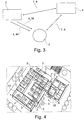
- FIG. 3 the data exchange between the marker 2, the data carrier 3 and the reader 4 is shown.
- the marker 2 which is preferably equipped with a motion sensor 10
- a low-frequency transmitter 12 and an infrared transmitter 13 a pulsed or pulsed low-frequency signal 5 is sent to a data carrier 3.
- an infrared signal 6 is sent with an identifier 40 to the data carrier 3.
- the data carrier 3 receives the identification 38 and the identifier 40 and transmits the data together with its own identification 39 with a radio signal (RF signal) 7, 8 to a reader 4.
- the reader 4 can also communicate with the marker 2 via an RF signal 7, 8.
- FIG. 4 a plan view of a building 32 is shown, wherein within the building 32 numerous rooms 33 are arranged.
- each room 33 has a marker 2. If a person now enters a certain room 33 together with the data carrier 3, the marker 2 registers the entry or movement with its movement sensor 10 and sends a low-frequency signal 5 with its low-frequency transmitter 12 to the data carrier 3.
- the data carrier 3 has a low-frequency receiver 19, which preferably operates pulsed or can also be operated permanently. If the data carrier 3 now receives the low-frequency signal 5 from the marker 2, then it switches its infrared interface 18 (IR receiver) on and waits for an infrared signal 6. Time-displaced or simultaneously the marker 2 transmits an infrared signal 6 to the infrared interface 13 Infrared receiver 18 of the data carrier 3.
- IR receiver infrared interface 18
- the disadvantage of the prior art is eliminated, since the low-frequency signals can radiate through space walls and is ensured only by an infrared connection, that the respective data carrier 3 is also in the corresponding room in which the marker 2 is arranged.
- the invention is not limited to an application of a marker in a particular space.
- a marker 2 can also over Entrances to be arranged in a building 32.
- the arrangement of a marker 2 in front of a building entrance or exit makes it easy to recognize an access or exit of a data carrier 3 or the associated person.
- the CPU 25 of the data carrier 3 processes the information obtained from the marker 2 together with its own information and sends it via an RF signal 7 to a reader 4, which is preferably arranged centrally in a building.
- This reader 4 receives the signal 7 via an RF transmitter / receiver 26 and processes this signal via a CPU 28 and passes the data obtained therefrom via an Ethernet interface 27 to a computer system 35.
- the computer system makes it easy to determine that a person wants to leave the building unauthorized, which is not authorized to do so. Access rights or restrictions can thus be set up by the higher-level computer system 35, so that it can be determined that the person X1 can only go into certain rooms or an alarm signal is triggered if this person X1 enters or leaves the premises without authorization.
- markers 2 with a fast pulsing of the low-frequency signal 5 are preferably arranged there.
- the respective room markers 2 in addition to the infrared motion sensor 10, it is also possible, for example, to perform a 5-minute pulsation of a low-frequency signal 5.
- FIG. 5 schematically the signal currents between the marker 2 and the data carrier 3 and the reader 4 are shown again.
- a movement 34 with a motion sensor 10 is detected.
- the marker 2 then sends a low-frequency signal 5, which is also designed as a wake-up signal, to a data carrier 3, which has a low-frequency receiver 19 and thus receives the low-frequency signal 5.
- an infrared signal 6 is sent to the same data carrier 3, which ensures that with correct reception of the data carrier 3 is in "sight distance" to the respective marker 2.
- the two transmitted signals 5.6 are processed in the data carrier 3 with the CPU 25 and passed as an RF signal 7 to a reader 4.
- This reader 4 has an RF transmitter / receiver 26 and returns a response signal in the form of an RF signal 8 to the respective data carrier 3.
- the data obtained are processed in the reader 4 and transmitted via an Ethernet signal 27 to a computer interface 35.
- FIG. 5 shows a further preferred embodiment in which, for example, a low-frequency signal 5 clocked at intervals of 30 seconds in the respective room 33 is sent.
- the low-frequency signal 5 is transmitted manually via a button 15 to the respective data carrier 3.
- the transmitted information may include the key number and may be interpreted as an alarm.
- FIG. 6 shows a person 36, which carries a data carrier 3 on the wrist.
- the person 36 moves in the direction of movement 34 within a room 33, wherein the movements are detected by a motion sensor 10.
- the marker 2 sends, either simultaneously or staggered, in each case a low-frequency signal 5 and an infrared signal 6 to the data carrier 3 of the person 36th
- the data carrier 3 links the received identification 38, 40 with its own identification 39 and sends this data via a radio link 7, 8 to a reader 4.
- the data carrier 3 has a gyroscope 20.
- the gyroscope 20 can be used to detect changes in position or direction.
- the data carrier 3 is designed as a bracelet, a movement of the respective person can be detected by the gyroscope. Likewise, a dead man's statement can be made. The data obtained are then transmitted to the reader 4.
- the reader 4 processes the data and sends it via an Ethernet connection 27 to a computer system 35.
- the computer system 35 can then use software to match the actual state with the desired state. Thus, it can be determined, for example, whether a person is asleep or if you are moving.
- Decisive in the present invention is that only by the combination of a low-frequency signal 5 and an infrared signal 6, a data carrier 3 can be accurately located.
Landscapes
- Engineering & Computer Science (AREA)
- Radar, Positioning & Navigation (AREA)
- Remote Sensing (AREA)
- Computer Networks & Wireless Communication (AREA)
- Physics & Mathematics (AREA)
- General Physics & Mathematics (AREA)
- Radar Systems Or Details Thereof (AREA)
Description
- Die Erfindung betrifft ein Verfahren und eine Vorrichtung zur Lokalisierung von Objekten oder Personen innerhalb von Gebäuden.
- Aus dem Stand der Technik sind Real-Time-Location-Systeme (RTLS) mit unterschiedlichen Techniken bekannt, welche Objekte oder Personen per Funk lokalisieren. So kommen beispielsweise zellenbasierte Lokalisierungen zum Einsatz, bei denen eine Antenne eine Zone im Raum definiert. Die Antenne ist mit einem Computersystem verbunden, welches die empfangenen Daten verarbeitet und weiterleitet.
- Ebenso sind Positionsmarker bekannt, die durch Übermittlung ihrer Identifikationsnummer an einen mobilen Datenträger eine Zone bzw. einen Bereich mitteilen. Bei allen Techniken werden Positionsmarker eingesetzt, die mit einer Funktechnologie entweder den mobilen Datenträger oder direkt dem Computersystem, die Lokalisierung des Datenträgers übermitteln.
- Derzeit werden beispielsweise Technologien eingesetzt, welche zur Lokalisierung bzw. Identifikation entweder Niederfrequenzfunk (125 kHz), Hochfrequenzfunk (433 MHz, 868 MHz, 2.4 GHz), Infrarot oder Ultraschall verwenden.
- Mit der Druckschrift
US 5,661,471 wird ein System zum Lokalisieren von Personen offenbart. Hierbei gibt der Datenträger erst beim Aktivieren eines Knopfes seine Informationen preis, wobei anschließend von einem Reader die Information aufgenommen und an den jeweiligen Server weitergegeben wird. Die Übermittlung des Signals bzw. der Information erfolgt über ein IR-Signal oder Ultraschall. Nachteil bei dieser Ausführungsform ist, dass z.B. im Bereich von Altenheimen, die Person, die den Sender trägt, immer aktiv handeln muss, um die jeweilige Position an den Reader zu übermitteln. Selbstverständlich wäre eine automatische Taktung des Tags möglich, dies würde jedoch eine hohe Batterieleistung erfordern. - Die
DE 10 2008 031 923 A1 beschreibt ein Verfahren zur Überwachung eines Raumes, wobei eine Triangulation der Signalstärke durchgeführt wird. Anhand der Signalstärken lässt sich somit die jeweilige Position des Datenträgers im Raum feststellen. - Mit der
DE 60 2005 001 007 T2 wird ein System zur Überwachung eines Raumes offenbart. In einem ersten Anwendungsbeispiel kommt ein Bewegungsmelder in Form eines PIR-Sensors (passive infrared) zum Einsatz, welcher eine Bewegung im Raum feststellt. Mit der Druckschrift findet jedoch keine Lokalisierung bzw. keine Identifikation eines Datenträgers innerhalb eines Raumes statt. - Mit der
US 5,917,425 wird ein System mit IR-/ RF-Modulen offenbart. Zwar kann bei diesem System eine Person innerhalb eines Raumes lokalisiert werden bzw. festgestellt werden, jedoch findet keine genaue Identifizierung statt. Ein Nachteil besteht darin, dass die Datenträger-Information lediglich durch ein IR-Signal übermittelt wird und anschließend von einem RF-Sender an den RF-Reader weitergegeben wird. Hierbei muss jedoch eine sichtbare Verbindung für eine wirkungsvolle Infrarot-Signalübertragung ausgehend von dem Tag gegeben sein. - Die bisher bekannten Systeme aus dem Stand der Technik weisen den Nachteil auf, dass entweder eine Funktechnologie oder eine Infrarottechnologie eingesetzt wird, was den alltäglichen Gebrauch limitiert. Zum Beispiel funktioniert ein Infrarotmarker nicht mit Datenträgern die abgedeckt sind. Niederfrequenzmarker funken durch Wände und können somit nicht Raumgenau lokalisieren. Des Weiteren werden die aktuellen Marker über ein Kabel mit Strom versorgt, was sehr aufwendig und teuer ist. Darüber hinaus funken die Marker permanent und belasten somit das Übertragungsmedium. Dies geht soweit, dass einige Länder gemäß dem Versorgungsprinzip nicht permanent in der Nähe von Lebewesen eingesetzt werden dürfen.
-
WO 2005/041142 A2 beschreibt den nächstliegenden Stand der Technik und offenbart ein Verfahren zur Lokalisierung eines Objektes, wobei ein Datenträger des Objekts (Objekt Tag) ein Radiosignal gefolgt von einem Infrarotsignal sendet. Das Infrarotsignal ist sehr kurz wodurch Energie gespart wird. -
WO 2011/062659 A1 offenbart eine Vorrichtung zur Lokalisierung eines Objektes, wobei der Datenträger am Objekt zum Senden von Infrarot- und Radiowellen ausgebildet ist, während im Raum Infrarot-Empfänger und Radiowellen-Empfänger vorhanden sind. Es ist beschrieben, dass die Funktion der Sender des Datenträgers und der Empfänger im Raum auch vertauscht werden kann. -
WO 01/33748 A1 - Die
US 2008/061967 A1 beschreibt das Aufwecken des Objekt-Tags mittels Infrarot. - Die
US 2008/218351 A1 beschreibt ein Objekt-Tag mit InfrarotSender/Empfänger und Radiowellen-Sender, wobei der Objekt-Tag periodisch aufgeweckt wird, um zu testen ob ein Infrarot-Triggersignal empfangen werden kann. - Der Erfindung liegt die Aufgabe zugrunde, eine Vorrichtung zur Lokalisierung eines Objektes z.B. einer Person so weiterzubilden, dass das Objekt genauer und besser lokalisiert werden kann. Ferner soll ein möglichst geringer Energieverbrauch des tragbaren Datenträgers erreicht werden.
- Zur Lösung der gestellten Aufgabe dient die technische Lehre der Ansprüche 1 und 6.
- Wesentliches Merkmal der Erfindung ist, dass die Vorrichtung einen kombinierten Einsatz aus einem Niedrigfrequenzsignal und einem Infrarotsignal vorsieht, um ein Objekt zu Lokalisieren.
- In einer ersten bevorzugten Ausführungsform ist der Marker als Multifrequenz-Lokalisierungs-Marker (MLM) ausgebildet und als fix montierter Transceiver in einem abgeschlossenen Raum innerhalb eines Gebäudes angeordnet. Der Transceiver stellt eine konstruktive Baueinheit aus einem Sender und einem Empfänger dar.
- Der Marker ist bevorzugt mit einem passiven Infrarotsensor (PIR) gekoppelt, welcher unter Ausnutzung der Pyroelektrizität seiner Empfängerfläche auf eine Temperaturänderung reagiert. Betritt nun eine Person den abgeschlossenen Raum, so wird die Bewegung von dem PIR-Sensor erfasst und der Marker aktiviert. Der Marker sendet nun ein Niederfrequenz-Aufweck-Signal an einen tragbaren Datenträger.
- Der tragbarere Datenträger, im Folgenden auch Tag genannt, ist entweder an einer Person angeordnet oder an einem bewegbaren Objekt, wie z.B. einem medizinischen Untersuchungsgerät oder einem Krankenbett. Trägt eine Person den Datenträger, so kann dieser beispielsweise als Armband oder als Namensschild ausgebildet sein. Die Erfindung soll hierauf jedoch nicht beschränkt sein, selbstverständlich sollen sämtliche Datenträgerausbildungen unter den Schutz dieser Anmeldung fallen.
- Der Datenträger erhält nun ein Aufweck-Signal (z.B. Niederfrequenz), welches bereits eine Identifikation des Raumes (Zone) bzw. eines Teilbereiches (Subzone) enthält. Diese Identifikation kann im Marker vorkonfiguriert sein. Der Datenträger liest und speichert diese Identifikationsnummern (Zone und Subzone) und schaltet seinen Infrarotempfänger an, um zu Überprüfen, ob der Marker, welcher das Aufwecksignal mit der Identifikation gesendet hat, "Sichtbar" ist.
- Innerhalb einer vordefinierten Zeit sendet der Marker ein Infrarotsignal mit einer Kennung. Diese Kennung kann ebenfalls eine Identifikation enthalten. Nachdem der Datenträger sowohl das Niederfrequenzsignal, als auch das Infrarotsignal empfangen hat, sendet er eine Bestätigung mit einer Identifikation per Hochfrequenzfunk an eine Empfangsantenne, die diese Information per LAN an ein Computersystem weiterleitet. Die ausgesendete Information kann hierbei Informationen über die neu empfangene Zone und Subzone enthalten.
- Durch die Kombination aus einem Niederfrequenzsignal und einem Infrarotsignal, welche beide an den gleichen Datenträger gesendet werden, entstehen folgende Vorteile:
- Der Datenträger kann Batteriebetrieben werden, es entfallen Verkabelungskosten. Die Bauteilgröße kann stark reduziert werden.
- Die Positionsbestimmung des Datenträgers funktioniert Raumgenau und Etagengenau, da die genaue Lokalisierung erst abgeschlossen ist, wenn der Datenträger sowohl das Niederfrequenz, als auch das Infrarotsignal empfange hat.
- Eine grobe Positionsbestimmung funktioniert auch wenn der Datenträger abgedeckt ist, denn hier wurde nur das Niederfrequenzsignal von dem Datenträger empfangen und per Hochfrequenzfunk an die Empfangsantenne weitergeleitet.
- Eine Lokalisierung des Datenträgers kann nun wie folgt ablaufen:
- Der Marker sendet ein Niederfrequenzsignal mit einer Identifikation aus.
- Das Niederfrequenzsignal wird in einem zweiten Verfahrensschritt von dem Datenträger empfangen, worauf dieser eine Infrarotschnittstelle aktiviert. Das Niederfrequenzsignal kann eine Identifikation, wie z.B. über die Zone bzw. Subzone enthalten.
- Zeitnah sendet der Marker ein Infrarotsignal mit einer Kennung an den gleichen Datenträger aus. Unter zeitnahem Versenden versteht die Erfindung, dass das Niederfrequenzsignal entweder gleichzeitig mit dem Infrarotsignal ausgesendet wird oder eine bestimmte Zeit später.
- Bei der von der Infrarotschnittstelle ausgesendeten Kennung kann es sich entweder um einfaches Signal handeln, welches der Datenträger verwendet, um den "Sichtkontakt" zu überprüfen oder die Kennung enthält mehrere Informationen, wie z.B. über die Zone bzw. Subzone.
- Der Datenträger empfängt das Infrarotsignal und verknüpft die empfangenen Informationen aus dem Niederfrequenz- und Infrarotsignal mit seiner Identifikation und sendet die gewonnen Daten an einen Reader.
- Der Reader leitet die gewonnen Daten an ein Computersystem weiter, welches die Lokalisierung auswertet. Solch eine Auswertung kann beispielsweise mit einer Software erfolgen. Mit Hilfe der Software lässt sich dann das jeweilige Objekt beispielsweise innerhalb eines Gebäudes lokalisieren. Ebenso kann über die Software bestimmte Rechte, wie Zugangsrechte etc. verwaltet werden.
- Ein Vorteil bei der Kombination aus Niederfrequenz- und Infrarot-Technik ist, dass der Niederfrequenz-Sender den Datenträger erstmalig aufweckt und dadurch der Datenträger sehr Batterie sparend betrieben werden kann. Dies ist ein wesentlicher Vorteil, denn somit kann der Tag relativ klein ausgebildet werden und von einer Person beispielsweise am Handgelenk getragen werden.
- Das Lokalisierungsverfahren ist durch die Kombination der beiden Signalübertragungstechniken genauer, da mit der Niederfrequenz-Technik zwar eine Lokalisierung der Person innerhalb eines Raumes bzw. sogar unter einer Bettdecke festgestellt werden kann, jedoch findet mit der IR-Technik eine genaue, bzw. raumgebundene Lokalisierung statt.
- Durch das Aussenden des Niederfrequenz-Signals an den Tag wird dieser aufgeweckt und gibt seine Informationen preis. Somit lässt sich grob feststellen, wo die Person sich befindet. Da die Niederfrequenz-Übertragungsmethode auch durch Wände überträgt, ist eine genauere Bestimmung durch eine Infrarotübertragung notwendig. Für eine funktionierende Infrarot-Übertragung muss eine Sichtverbindung zwischen dem im Raum installierten Sender bzw. Reader und dem Datenträger zu Verfügung stehen. Dadurch lässt sich die Person innerhalb eines Raumes genauer Lokalisieren, da erst durch die Sichtverbindung des Infrarot-Signals diese Person in dem jeweiligen Raum erkannt werden kann.
- Der Erfindungsgegenstand der vorliegenden Erfindung ergibt sich nicht nur aus dem Gegenstand der einzelnen Patentansprüche, sondern auch aus der Kombination der einzelnen Patentansprüche untereinander.
- Alle in den Unterlagen, einschließlich der in der Zusammenfassung offenbarten Angaben und Merkmale, insbesondere die in den Zeichnungen dargestellte räumliche Ausbildung, werden als erfindungswesentlich beansprucht, soweit sie einzeln oder in Kombination gegenüber dem Stand der Technik neu sind.
- Im Folgenden wird die Erfindung anhand von lediglich einem Ausführungsweg darstellenden Zeichnungen näher erläutert. Hierbei ergehen aus den Zeichnungen und ihrer Beschreibung weitere erfindungswesentliche Merkmale und Vorteile der Erfindung hervor.
- Figur 1:
- Schematische Darstellung der erfindungswesentlichen Vorrichtung zur Lokalisierung von Personen bzw. Objekten
- Figur 2:
- Schematische Darstellung der Vorrichtung
- Figur 3:
- Schematische Darstellung des Datenaustausches zwischen dem Marker, dem Datenträger und dem Reader
- Figur 4:
- Draufsicht auf ein Gebäude, in welchem die erfindungswesentliche Vorrichtung installiert ist.
- Figur 5:
- Schematische Darstellung der einzelnen Signalübertragungsmethoden zwischen dem Marker, dem Datenträger und dem Reader/ Lesegerät
- Figur 6:
- Darstellung einer Person innerhalb eines Zimmers mit der erfindungswesentlichen Vorrichtung
- Mit der
Figur 1 wird eine schematische Darstellung der erfindungswesentlichen Vorrichtung gezeigt. - Die Vorrichtung 1 besteht in einer ersten Ausführungsform im Wesentlichen aus einem Marker 2, einem Datenträger 3 und einem Reader 4.
- Der Marker 2 ist hierbei so ausgebildet, dass er als Kästchen bzw. als Kasten in einem Raum unauffällig installiert werden kann, wobei eine erhöhte Position von Vorteil ist. Um eine Person bzw. ein Objekt innerhalb eines Gebäudes genau Lokalisieren zu können, ist bevorzugt in jedem Raum solch ein Marker 2 installiert.
- Die Räume innerhalb des Gebäudes können als Zonen bzw. Subzonen definiert sein. Jeder Raum ist mit einer eigenen Identifikation 38 im Marker 2 hinterlegt. Bei besonderes großen Räumen können mehrere Marker 2 entfernt voneinander installiert sein, welche jeweils eine Identifikation 38 für den Raum (=Zone) und die jeweilige Position im Raum (Suzone) enthalten können.
- Der Marker 2 weist einen RF-Sender/ Empfänger 11 auf, mit dem er Funksignale entweder empfangen oder aussenden kann. Des Weiteren weist der Marker 2 einen Niederfrequenzsender auf, wobei der Sendevorgang des Niederfrequenzsignals entweder permanent ein, permanent aus oder gepulst erfolgen kann.
- Des Weiteren weist der Marker 2 einen Infrarotsender 13 auf, mit welchem Infrarotsignale 6 innerhalb des Raumes übertragen werden können. Für eine besonders gut Übertragung der Infrarotsignale 6 mit dem jeweiligen Objekt bzw. mit der jeweiligen Person, ist der Marker 2 bevorzugt in einer erhöhten Position innerhalb des Raumes angeordnet.
- Um den Eintritt einer Person bzw. die Bewegung eines Objektes innerhalb eines abgeschlossenen Raumes festzustellen, weist der Marker 2 bevorzugt einen Bewegungssensor 10 auf, welcher beispielsweise mithilfe von Infrarotsignalen eine Bewegung der jeweiligen Person bzw. des Objektes innerhalb eines abgeschlossenen Raumes feststellen kann.
- Des Weiteren weist der Marker 2 einen Taster 15 auf, mit welchem eine manuelle Aktivierung möglich ist. Die manuelle Aktivierung kann beispielweise immer dann verwendet werden, wenn sich mehrere Objekte bzw. Personen in einem Raum befinden und eine aktuelle Lokalisierung aller, relativ zeitnah stattfinden soll.
- Zur Stromversorgung kann der Marker 2 bevorzugt mit dem Stromnetz des Hauses versorgt werden. Es ist jedoch ebenso ein Batteriebetrieb oder dergleichen zur Stromversorgung möglich.
- Der Marker 2 sendet entweder gepulst oder in Abhängigkeit des Bewegungssensors 10 ein Niederfrequenzsignal 5 mit einem Niederfrequenzsender 12 (LF-Sender) aus, welches von einem Datenträger 3 und seinem Niederfrequenzempfänger 19 empfangen wird. Dieses Niederfrequenzsignal 5 dient als Aufwachsignal für den Datenträger 3. Der Datenträger 3 empfängt über das Niederfrequenzsignal 5 eine erste Identifikation 38, welche beispielsweise die Raumnummer, die Raumgröße, die Temperatur des Raumes, die Position des Raumes innerhalb des Gebäudes oder eine Information, wie z.B. Fenster offen enthält.
- Um eine genaue Lokalisierung des Datenträgers 3 innerhalb eines Raumes zu gewährleisten, sendet mit kurzem zeitlichem Abstand der Marker 2 ein weiteres Signal in Form eines Infrarotsignal 6 mit einem Infrarotsender 13 (IR-Sender) an den Datenträger 3 aus. Besteht nun eine Sichtverbindung zwischen dem Marker 2 und dem Datenträger 3, so kann das Infrarotsignal 6 wirksam übertragen werden. Durch die wirksame Übertragung des Infrarotsignals 6 ist gewährleistet, dass sich der Datenträger in dem jeweiligen Raum befindet.
- Das Infrarotsignal 6 des Markers 2 wird beim Datenträger 3 mit einem Infrarotempfänger 18 empfangen. Das Niederfrequenzsignal 5 des Markers 2 wird beim Datenträger 3 mit dem Niederfrequenzempfänger 19 empfangen.
- Der Datenträger 3 weist eine Stromversorgung auf, welche bevorzugt als Batterie ausgebildet ist. Dadurch dass der Datenträger 3 im Normalfall lediglich im Standby-Modus betrieben wird und nur durch das Niederfrequenzsignal 5, welches vom Marker 2 ausgesendet wird, aufgeweckt wird, ist diese Ausführungsform sehr stromsparend ausgebildet.
- Der Datenträger 3 empfängt von dem Marker über das Niederfrequenzsignal 5 eine Identifikation 38 und über das Infrarotsignal 6 eine Kennung 40. Die Identifikation 38 enthält beispielsweise die Raumidentifikation. Die Kennung 40 kann als einfaches IR-Signal ausgebildet sein, welches lediglich dazu dient, um die Sichtverbindung zwischen dem Marker 2 und dem Datenträger 3 zu überprüfen. Selbstverständlich kann die Kennung 40 auch weitere Informationen bzw. Identifikationen enthalten. Auch ist es möglich, dass die Informationen aus der Identifikation 38 und der Kennung 40 gleich sind.
- Nachdem nun der Datenträger 3 die Signale 5,6 empfangen hat, verknüpft er diese mit seiner eigenen Identifikationsinformation 39 zu einem Datenpaket. Die Identifikation 39 des Datenträgers 3 kann beispielsweise Angaben über die jeweilige Person enthalten, die den Datenträger 3 trägt. Ebenso kann die Identifikation 39 eine Information über das Objekt beinhalten, an welchem der Datenträger 3 angeordnet ist.
- In einer ersten Ausführungsform kann der Datenträger 3 als Armband ausgebildet sein und Identifikationsinformationen 39 wie beispielsweise den Namen, das Alter, besondere Gesundheitsmerkmale und Zugangsbeschränkungen enthalten.
- In einer weiteren bevorzugten Ausführungsform ist der Datenträger 3 an einem Objekt angebracht, wobei der Datenträger Identifikationsinformationen 39 über das Objekt gespeichert hat, wie z.B. das Objekt ist ein EKG-Gerät oder das Objekt ist ein Krankenbett mit der Nummer XYZ.
- Ebenso ist mit dem erfindungswesentlichen Datenträger eine Temperatur-Aufzeichnung und Lokalisierung von Essenswagen innerhalb eines Gebäudes wie z.B. im Krankenhaus möglich.
- In einer weiteren Ausführungsform kann beispielsweise der Datenträger 3 an einer Akte in einer Anwaltskanzlei angeordnet sein und Identifikationsinformationen 39 über den Akteninhalt enthalten. Die zu suchende Akte kann dann leicht im Gebäude lokalisiert werden.
- Selbstverständlich lassen sich jegliche Identifikationsinformationen 39 auf dem Datenträger 3 speichern, sodass dieser universell eingesetzt werden kann.
- In einer weiteren Ausführungsform kann beispielsweise der Datenträger 3 bei einer Archiv-Überwachung eingesetzt werden, wobei festgestellt werden kann, ob eine autorisierte Person sich im Archiv bzw. Lager befindet und bewegt.
- Ebenso kann eine Überwachung eines einzelnen Arbeitsplatzes durchgeführt werden. Die jeweilige Person trägt den Datenträger 3 und kann somit leicht innerhalb eines Raumes bzw. Gebäudes geortet werden. Auch wäre eine Totman-Überwachung der Person denkbar.
- Ein weiteres Anwendungsbeispiel wäre der Einsatz des Datenträgers 3 für ein Zutritts- und Ticketing-System in Museen. Durch die exakte Lokalisierung des Datenträgers kann beispielsweise eine interaktive Show in einem bestimmten Bereich innerhalb eines Gebäudes gestartet werden.
- Der Datenträger 3 weist des Weiteren einen Radiofrequenz-Sender bzw. RF-Empfänger 11 auf, womit er Funksignale 7, 8 senden und empfangen kann. Unter einem RF-Sender/ Empfänger 17 versteht die vorliegende Erfindung eine Funkschnittstelle, mit welcher Funksignale empfangen bzw. gesendet werden kann. Der Funksignalaustausch erfolgt mit einem entfernten Reader 4.
- Bei dem aussendenden RF-Signal 7 handelt es sich bevorzugt um Informationen, welche der Datenträger 3 vorher von dem Marker 2 bekommen hat und mit seiner eigenen Information verknüpft hat. Diese kombinierte Information, welche bevorzugt aus einer Rauminformation und einer Personen- bzw. Objekt-ID besteht, wird dann über ein RF-Signal 7 an einen Reader 4 weitergeleitet.
- Der Reader 4 hat ebenfall einen RF-Sender/ -Empfänger 26, womit er Funksignale 7 und 8 des Datenträgers 3 empfangen und aussenden kann. Ferner weist der Reader 4 ein kabelgebundenes Datennetz auf, welches z.B. eine Internet- bzw. Ethernetverbindung 27 ist und womit er die gewonnenen Daten des Datenträgers 3 durch ein Signal, wie z.B. einem Ethernetsignal 9 an ein Computersystem 35 weiterleiten kann. Der Reader 4 dient somit als Schnittstelle zwischen dem Datenträger 3 und dem Computersystem 35.
- Sowohl der Datenträger 3, als auch der Reader 4 weisen eine Stromversorgung 23 bzw. 31 auf, welche bevorzugt als Batterie ausgebildet ist. Es ist jedoch auch eine andere Stromversorgung, wie z. B. eine Netzstromversorgung oder dergleichen möglich. Der Reader 4 kann ferner mit einer LED-Anzeige 30 ausgestattet sein, welche graphisch den Betriebszustand des Readers 4 darstellt.
- Mit der
Figur 2 wird eine genauere, schematische Darstellung der erfindungswesentlichen Lokalisierungsvorrichtung dargestellt. - Ausgehend von dem Sender 2 weist dieser eine CPU 24 auf, welche sowohl den NF-Sender 12 (Niederfrequenzsender), als auch den Infrarotsender 13 und den Funksender 11 bzw. Empfänger steuert. Des Weiteren weist der Sender 2 einen Infrarotbewegungssensor 10 auf. Zur manuellen Aktivierung kann der Sender 2 noch einen Taster 15 aufweisen und eine optische Signalleuchte in Form einer LED-Anzeige 16. Die Stromversorgung des Markers 2 erfolgt über Batterie 24 Volt, 230 Volt oder eine Power-Over-Ethernet (POE) -Verbindung.
- Der Marker 2 sendet mit einem Niederfrequenzsender 12 ein Niederfrequenzsignal 5 an einen Datenträger 3, welcher das Niederfrequenzsignal 5 mit dem Niederfrequenz-Empfänger 19 empfängt. Zeitgleich bzw. zeitlich versetzt wird ein Infrarotsignal 6, ausgehend von dem Marker 2 bzw. dem dort angeordneten Infrarotsender 13, an den Datenträger 3 und dessen Infrarotempfänger 18 ausgesendet. Bei der Übertragung des Niederfrequenzsignals 5 bzw. des Infrarotsignals 6 sendet der Marker 2 eine Identifikation 38 und eine Kennung 40 an den Datenträger 3, welcher diese mit einer CPU 25 auswertet und anschließend mit Hilfe eines RF-Sender/ Empfängers 17 und einem RF-Signal 7 an einen Reader 4 weiterleitet.
- Der Reader 4 weist für den Empfang bzw. für das Aussenden der RF-Signale 7, 8 hierfür einen RF-Sender/ Empfänger 26 auf. Um den Reader 4 manuell zu aktivieren weist dieser bevorzugt eine Taste 29 auf. Für die Betriebszustandsanzeige ist der Reader 4 mit LED-Anzeige 30 ausgestattet.
- Die Stromversorgung 31 des Readers 4 erfolgt bevorzugt über einen Batteriebetrieb. Es ist jedoch auch eine Stromversorgung mit 24 Volt, 230 Volt oder eine Power-Over-Ethernet (POE) möglich. Der Reader 4 verarbeitet die empfangenen Signale 7 mit seiner CPU 28 und leitet diese mit einem Ethernetsignal 9 über ein Ethernetmodul 27 an ein Computersystem 35 weiter.
- Das Computersystem 35 weist eine Verwaltungssoftware bzw. Benutzeroberfläche auf, mit welcher sich die einzelnen Informationen der jeweiligen Marker 2 bzw. Datenträger 3 verwalten lassen.
- So kann beispielsweise überwacht werden, ob sich der jeweilige Datenträger 3 noch in dem bestimmten Raum mit dem Marker 2 aufhält. Dies kann beispielsweise ein Patient oder ein Arzt in einem Krankenhaus sein.
- Ebenso kann eine Überwachung der Ein- und Ausgänge eines Gebäudes erfolgen. Dies ist besonders wichtig, wenn sichergestellt sein muss, dass bestimmte Personen nicht das Gebäude verlassen sollten.
- Des Weiteren können bestimmte Objekte, wie z.B. eine besondere medizinische Apparatur leicht anhand des der angeordneten Datenträgers 3 lokalisiert werden.
- Mit der
Figur 3 wird der Datenaustausch zwischen dem Marker 2, dem Datenträger 3 und dem Reader 4 dargestellt. Ausgehend von dem Marker 2, welcher bevorzugt mit einem Bewegungssensor 10, einem Niederfrequenzsender 12 und einem Infrarotsender 13 ausgestattet ist, wird ein gepulstes bzw. getaktetes Niederfrequenzsignal 5 an einen Datenträger 3 gesendet. - Gleichzeitig bzw. zeitlich versetzt wird ein Infrarotsignal 6 mit einer Kennung 40 an den Datenträger 3 gesendet.
- Der Datenträger 3 empfängt die Identifikation 38 und die Kennung 40 und gibt die Daten zusammen mit seiner eignen Identifikation 39 mit einem Funksignal (RF-Signal) 7, 8 an einen Reader 4 weiter. Der Reader 4 kann ebenso über ein RF-Signal 7, 8 mit dem Marker 2 kommunizieren.
- Mit der
Figur 4 wird eine Draufsicht eines Gebäudes 32 gezeigt, wobei innerhalb des Gebäudes 32 zahlreiche Zimmer 33 angeordnet sind. - Bei einer bevorzugten Ausführungsform weist jedes Zimmer 33 einen Marker 2 auf. Betritt nun eine Person zusammen mit dem Datenträger 3 ein bestimmtes Zimmer 33, so registriert der Marker 2 den Eintritt bzw. die Bewegung mit seinem Bewegungssensor 10 und sendet ein Niederfrequenzsignal 5 mit seinem Niederfrequenzsender 12 an den Datenträger 3.
- Der Datenträger 3 weist einen Niederfrequenzempfänger 19 auf, welcher bevorzugt gepulst arbeitet bzw. auch permanent betrieben werden kann. Empfängt nun der Datenträger 3 das Niederfrequenzsignal 5 von dem Marker 2, so schaltet dieser seine Infrarotschnittstelle 18 (IR-Empfänger) ein und wartet auf ein Infrarotsignal 6. Zeitlich versetzt bzw. gleichzeitig sendet der Marker 2 mit seiner Infrarotschnittstelle 13 ein Infrarotsignal 6 an den Infrarotempfänger 18 des Datenträgers 3.
- Durch die Sichtverbindung zwischen dem Marker 2 und dem Datenträger 3 ist nun gewährleistet, dass sich der Datenträger 3 bzw. die tragende Person bzw. das Objekt innerhalb eines bestimmten Zimmers 33 befindet.
- Damit wird der Nachteil nach dem Stand der Technik behoben, da die Niederfrequenzsignale auch durch Raumwände strahlen können und nur durch eine Infrarotverbindung gewährleistet ist, dass sich der jeweilige Datenträger 3 auch in dem dazugehörigen Raum befindet, in welchem der Marker 2 angeordnet ist.
- Die Erfindung ist jedoch nicht auf eine Anwendung eines Markers in einem bestimmten Raum beschränkt. Solch ein Marker 2 kann ebenso auch über Eingängen in einem Gebäude 32 angeordnet sein. Durch die Anordnung eines Markers 2 vor einem Gebäudeeingang bzw. Ausgang lässt sich leicht ein Zugang bzw. Austritt eines Datenträgers 3 bzw. die dazugehörige Person erkennen.
- Die CPU 25 des Datenträgers 3 verarbeitet die gewonnenen Informationen des Markers 2 zusammen mit ihrer eigenen Information und sendet diese über ein RF-Signal 7 an einen Reader 4, welcher bevorzugt zentral in einem Gebäude angeordnet ist. Dieser Reader 4 empfängt das Signal 7 über einen RF-Sender/ Empfänger 26 und verarbeitet dieses Signal über eine CPU 28 und gibt die daraus gewonnenen Daten über eine Ethernet-Schnittstelle 27 an ein Computersystem 35 weiter.
- Durch das Computersystem kann leicht festgestellt werden, dass sich eine Person unerlaubt aus dem Gebäude entfernen will, welch hierfür nicht befugt ist. Durch das übergeordnete Computersystem 35 können somit Zugriffsrechte bzw. Einschränkungen eingerichtet werden, sodass bestimmt werden kann, dass die Person X1 nur in bestimmte Räume gehen kann bzw. ein Alarmsignal ausgelöst wird, wenn diese Person X1 unerlaubt in andere Räume eintritt bzw. austritt.
- Um die Ein- und Ausgänge besser überwachen zu können, sind dort bevorzugt Marker 2 mit einer schnellen Pulsung des Niederfrequenzsignals 5 angeordnet. Bei den jeweiligen Zimmer-Markern 2 kann, neben dem Infrarotbewegungssensor 10, auch beispielsweise eine 5 minütige Pulsung eines Niederfrequenzsignals 5 erfolgen.
- Mit der
Figur 5 sind schematisch noch einmal die Signalströme zwischen dem Marker 2 und dem Datenträger 3 und dem Reader 4 dargestellt. - Ausgehend von dem Marker 2, welcher bevorzugt eine Infrarotschnittstelle 13 aufweist, wird eine Bewegung 34 mit einem Bewegungssensor 10 erkannt. Daraufhin sendet der Marker 2 ein Niederfrequenzsignal 5, welches auch als Aufwachsignal ausgebildet ist, an einen Datenträger 3, der einen Niederfrequenzempfänger 19 aufweist und somit das Niederfrequenzsignal 5 empfängt.
- Mit zeitlichem Abstand bzw. gleichzeitig wird, ausgehend von dem Marker 2, ein Infrarotsignal 6 an den gleichen Datenträger 3 gesendet, wodurch gewährleistet ist, dass bei korrektem Empfang der Datenträger 3 sich in "Sichtweite" zu dem jeweiligen Marker 2 befindet.
- Die beiden übermittelten Signale 5,6 werden im Datenträger 3 mit der CPU 25 verarbeitet und als RF-Signal 7 an einen Reader 4 weitergegeben. Dieser Reader 4 verfügt über ein RF-Sender/ Empfänger 26 und gibt ein Antwortsignal in Form eines RF-Signals 8 an den jeweiligen Datenträger 3 zurück. Die gewonnenen Daten werden im Reader 4 verarbeitet und über ein EthernetSignal 27 an eine Computerschnittstelle 35 weitergegeben.
-
Figur 5 zeigt eine weitere bevorzugte Ausführungsform, bei der beispielsweise ein Niederfrequenzsignal 5 getaktet im Abstand von 30 Sekunden in das jeweilige Zimmer 33 gesendet wird. - Ebenso ist es möglich, dass das Niederfrequenzsignal 5 manuell über einen Taster 15 an den jeweiligen Datenträger 3 ausgesendet wird. Hierbei kann die ausgesendete Information die Tastennummer beinhalten und kann als Alarm interpretiert werden.
- Die
Figur 6 zeigt eine Person 36, welche einen Datenträger 3 am Handgelenk trägt. Die Person 36 bewegt sich in Bewegungsrichtung 34 innerhalb eines Zimmers 33, wobei die Bewegungen durch einen Bewegungssensor 10 festgestellt werden. - Der Marker 2 sendet, entweder gleichzeitig oder zeitlich versetzt, jeweils ein Niederfrequenzsignal 5 und ein Infrarotsignal 6 an den Datenträger 3 der Person 36.
- Der Datenträger 3 verknüpft die empfangene Identifikation 38, 40 mit seiner eignen Identifikation 39 und sendet diese Daten über eine Funkverbindung 7,8 an einen Reader 4.
- In einer weiteren Vorteilhaftenausführungsform weist der Datenträger 3 ein Gyroskop 20 auf. Mithilfe des Gyroskops 20 lassen sich Lagen- bzw. Richtungsänderungen feststellen.
- Ist beispielsweise der Datenträger 3 als Armband ausgebildet, so kann durch das Gyroskop eine Bewegung der jeweiligen Person festgestellt werden. Ebenso kann eine Totmann-Feststellung getroffen werden. Die gewonnen Daten werden dann an den Reader 4 übertragen.
- Der Reader 4 verarbeitet die Daten und sendet diese über eine Ethernetverbindung 27 an ein Computersystem 35. Das Computersystem 35 kann dann über eine Software den Ist-Zustand mit dem Soll-Zustand abgleichen. Somit kann beispielsweise festgestellt werden, ob eine Person schläft oder ob Sie sich bewegt.
- Entscheidend bei der vorliegenden Erfindung ist, dass erst durch die Kombination aus einem Niederfrequenzsignal 5 und einem Infrarotsignal 6 ein Datenträger 3 genau lokalisiert werden kann.
-
- 1
- Vorrichtung
- 2
- Marker
- 3
- Datenträger (Tag)
- 4
- Reader/ Lesegerät
- 5
- Niederfrequenzsignal
- 6
- Infrarotsignal
- 7
- RF-Signal
- 8
- RF-Signal (Antwort)
- 9
- Ethernetsignal
- 10
- Bewegungssensor
- 11
- RF-Sender/ Empfänger von 2
- 12
- LF-Sender
- 13
- IR-Sender
- 14
- Stromversorgung von 2
- 15
- Taster
- 16
- Licht (LED)
- 17
- RF-Sender/ Empfänger von 3
- 18
- IR-Empfänger
- 19
- LF-Empfänger
- 20
- Gyroskop
- 21
- Taster
- 22
- LED
- 23
- Stromversorgung von 3
- 24
- CPU von 2
- 25
- CPU von 3
- 26
- RF-Sender/ Empfänger von 4
- 27
- Ethernet
- 28
- CPU
- 29
- Taster
- 30
- LED
- 31
- Stromversorgung von 4
- 32
- Gebäude
- 33
- Zimmer
- 34
- Bewegung
- 35
- Computersystem
- 36
- Person
- 37
- Objekt
- 38
- Identifikation von 2
- 39
- Identifikation von 3
- 40
- Kennung
Claims (10)
- Verfahren zur Lokalisierung eines Objektes z.B. einer Person (36) in einer Ort- oder Gebäudeumgebung und Darstellung des Aufenthaltsortes dieses Objektes auf einem Computersystem (35), wobei das Objekt einen Datenträger (3) aufweist und an ortfesten Referenzpunkten jeweils mindestens ein Marker (2) angeordnet ist, dadurch gekennzeichnet, dassa) in einem ersten Verfahrensschritt der Marker (2) ein Niederfrequenzsignal (5) mit einer Identifikation (38) aussendet,b) das Niederfrequenzsignal (5) in einem zweiten Verfahrensschritt von dem Datenträger (3) empfangen wird, worauf dieser eine Infrarotschnittstelle (18) aktiviert,c) zeitnah sendet der Marker (2) ein Infrarotsignal (6) mit einer Kennung (40) an den gleichen Datenträger (3) aus,d) der Datenträger (3) empfängt das Infrarotsignal (6) und verknüpft die empfangene Identifikation (38) und die Kennung (40) mit seiner Identifikation (39) und sendet die gewonnen Daten (38, 39, 40) an einen Reader (4),e) wobei der Reader (4) die Daten (38, 39, 40) an ein Computersystem (35) weiterleitet, welches die Lokalisierung auswertet.
- Verfahren nach Anspruch 1, dadurch gekennzeichnet, dass ein Bewegungssensor (10) eine Bewegung (34) des Objektes erfasst und anschließend den Marker (2) aktiviert.
- Verfahren nach einem der Ansprüche 1 oder 2, dadurch gekennzeichnet, dass der Marker (2) gepulst das Niederfrequenzsignal (5) aussendet.
- Verfahren nach einem der Ansprüche 1 bis 3, dadurch gekennzeichnet, dass der Datenträger (3) die Daten (38, 39, 40) mit einem Funksignal (7) über eine RF-Sender / Empfänger (17) an den Reader (4) sendet.
- Verfahren nach einem der Ansprüche 1 bis 4, dadurch gekennzeichnet, dass der Reader (4) die empfangenen Daten (38, 39, 40) aus dem Funksignal (7) verarbeitet und über ein kabelgebundene Datennetz an das Computersystem (35) weiterleitet.
- Vorrichtung zur Durchführung des Verfahrens nach Anspruch 1 zur Lokalisierung eines Objektes z.B. einer Person (36) in einer Ort- oder Gebäudeumgebung und Darstellung des Aufenthaltsortes dieses Objektes auf einem Computersystem (35), gekennzeichnet durch
mindestens einen Marker (2) zur Aussendung eines Niederfrequenzsignals (5) mit einer Identifikation (38) an einen Datenträger (3) und zum zeitnahen Senden eines Infrarotsignals (6) mit einer Kennung (40) an den gleichen Datenträger (3), wobei der Marker (2) an einem ortsfesten Referenzpunkt angeordnet ist,
den an dem Objekt angeordneten Datenträger (3) zum Empfang des Niederfrequenzsignals (5) und zur Aktivierung einer Infrarotschnittstelle (18) und Empfangen des Infrarotsignals (6) und Verknüpfen der empfangenen Identifikation (38) und der Kennung (40) mit seiner Identifikation (39) und Senden der gewonnen Daten (38, 39, 40) an einen Reader (4), und
den Reader (4) zum Weiterleiten der Daten (38, 39, 40) an das Computersystem (35), welches die Lokalisierung auswertet. - Vorrichtung nach Anspruch 6, dadurch gekennzeichnet, dass der Marker (2) einen Bewegungssensor (10) aufweist.
- Vorrichtung nach Anspruch 6 oder 7, dadurch gekennzeichnet, dass der Marker (2) und der Datenträger (3) einen Funksender und Funkempfänger (17) aufweist.
- Vorrichtung nach einem der Ansprüche 6 bis 8, dadurch gekennzeichnet, dass der Datenträger (3) über eine Batterie mit Strom versorgt wird.
- Vorrichtung nach einem der Ansprüche 6 bis 9, dadurch gekennzeichnet, dass der Marker (2) einen Taster (21) aufweist, welcher den Lokalisierungsvorgang des Datenträgers (2) manuell auslöst und eine zusätzlich Information überträgt.
Applications Claiming Priority (1)
| Application Number | Priority Date | Filing Date | Title |
|---|---|---|---|
| DE102013015222.4A DE102013015222A1 (de) | 2013-09-13 | 2013-09-13 | Verfahren und Vorrichtung zur Lokalisierung von Objekten |
Publications (2)
| Publication Number | Publication Date |
|---|---|
| EP2853913A1 EP2853913A1 (de) | 2015-04-01 |
| EP2853913B1 true EP2853913B1 (de) | 2017-11-08 |
Family
ID=51702959
Family Applications (1)
| Application Number | Title | Priority Date | Filing Date |
|---|---|---|---|
| EP14003108.9A Active EP2853913B1 (de) | 2013-09-13 | 2014-09-09 | Verfahren und Vorrichtung zur Lokalisierung von Objekten |
Country Status (4)
| Country | Link |
|---|---|
| EP (1) | EP2853913B1 (de) |
| DE (1) | DE102013015222A1 (de) |
| DK (1) | DK2853913T3 (de) |
| NO (1) | NO3025016T3 (de) |
Families Citing this family (2)
| Publication number | Priority date | Publication date | Assignee | Title |
|---|---|---|---|---|
| DE102015209707A1 (de) * | 2015-05-27 | 2016-12-01 | Tridonic Gmbh & Co Kg | Vorrichtung zur Kennzeichnung eines Gegenstandes |
| CN115236649B (zh) * | 2022-06-24 | 2026-01-16 | 江苏英特神斯科技有限公司 | 一种超声波室内三维定位系统及方法 |
Family Cites Families (12)
| Publication number | Priority date | Publication date | Assignee | Title |
|---|---|---|---|---|
| IL111550A (en) | 1994-11-07 | 1998-04-05 | Visonic Ltd | Signaling network system |
| US5917425A (en) | 1996-01-22 | 1999-06-29 | Wireless Communiations Products, Llc | IR/RF locator |
| IL132711A (en) * | 1999-11-03 | 2005-05-17 | Elpas Electro Optic Systems Lt | Dual rf/ir communication device and method of use thereof |
| US7907053B2 (en) * | 2003-05-14 | 2011-03-15 | Hill-Rom Services, Inc. | Combined locating, tracking and communications system |
| WO2005041142A2 (en) * | 2003-10-20 | 2005-05-06 | Radianse, Inc. | A location system for associating a first signal with a second signal |
| US7079028B2 (en) | 2004-03-11 | 2006-07-18 | Robert Bosch Gmbh | Modular intrusion detection system |
| US7982601B2 (en) * | 2004-03-22 | 2011-07-19 | Innovation Law Group, Ltd. | Multi-modal active RFID tag with biometric sensors, systems and methods of ITV tracking |
| EP1657562B1 (de) * | 2004-11-15 | 2010-01-06 | Saab Ab | Sendeeinheit |
| US7538666B2 (en) * | 2006-09-06 | 2009-05-26 | Grace Industries, Inc. | Automated accountability locating system |
| US8054160B2 (en) * | 2007-03-09 | 2011-11-08 | Innovation Law Group, Ltd. | RFID tag power conservation system and method |
| DE102008031923A1 (de) | 2008-07-08 | 2010-01-14 | Hochschule Ostwestfalen-Lippe | Verfahren für die Überwachung eines Raums |
| US8416072B2 (en) * | 2009-11-23 | 2013-04-09 | Versus Technology, Inc. | Real-time method and system for locating a mobile object or person in a tracking environment while conserving electrical energy in a battery-operated tracking tag associated with the object or person |
-
2013
- 2013-09-13 DE DE102013015222.4A patent/DE102013015222A1/de not_active Withdrawn
-
2014
- 2014-07-17 NO NO14747773A patent/NO3025016T3/no unknown
- 2014-09-09 DK DK14003108.9T patent/DK2853913T3/en active
- 2014-09-09 EP EP14003108.9A patent/EP2853913B1/de active Active
Non-Patent Citations (1)
| Title |
|---|
| None * |
Also Published As
| Publication number | Publication date |
|---|---|
| DK2853913T3 (en) | 2018-02-05 |
| NO3025016T3 (de) | 2018-02-17 |
| DE102013015222A1 (de) | 2015-03-19 |
| EP2853913A1 (de) | 2015-04-01 |
Similar Documents
| Publication | Publication Date | Title |
|---|---|---|
| DE69809281T2 (de) | Ortungsvorrichtung | |
| DE69918428T2 (de) | Verfahren und system zur ortung von gegenständen oder personen in einer lokalisierungsumgebung | |
| DE60115096T2 (de) | System zum identifizieren zusammengehöriger artikel | |
| DE69124230T2 (de) | Standortbestimmungssystem | |
| DE60016842T2 (de) | Hausgebundenes Überwachungssystem für den Gesundheitszustand | |
| DE69913678T2 (de) | System zur überwachung von gegenständen oder menschen | |
| DE102012105365A1 (de) | System und Verfahren zum Überwachen der Einhaltung der Hygienevorschriften | |
| DE10220366A1 (de) | Lokalisierungssystem mit einer Rückübertragung der Identifikationsinformation | |
| EP2215496B1 (de) | Verfahren zum erkennen von lebewesen | |
| EP2635998B1 (de) | Mobiles gerät und infrastruktursystem | |
| EP1426784B1 (de) | Vorrichtung und Verfahren zur Positionsbestimmung | |
| WO2013107574A1 (de) | Benutzung der belegungsrate von gebieten oder gebäuden zur personenstromsimulation | |
| DE102022211889A1 (de) | Verfahren zum Überwachen eines Kraftfahrzeugs und Kraftfahrzeug | |
| DE19713736A1 (de) | Vorrichtung und Verfahren zum Erfassen und Identifizieren von tragbaren Benutzerkennungseinheiten | |
| EP2853913A1 (de) | Verfahren und Vorrichtung zur Lokalisierung von Objekten | |
| EP1929451B1 (de) | Vorrichtung zur überprüfung des vorhandenseins von gegenständen | |
| DE19506392C2 (de) | Signalübertragungssystem für kurze Reichweiten | |
| DE102008006044B4 (de) | Überwachungssystem und Verfahren zur Verlusterkennung im Hinblick auf zumindest ein zu überwachenden Objekt | |
| WO2019175414A2 (de) | Gebäude-sensorsystem | |
| CN106127617A (zh) | 一种基于突发事件下的室内人员定位监控系统及方法 | |
| EP4270347B1 (de) | Sicherheitssystem | |
| DE202020107501U1 (de) | Vorrichtung zur Aufenthaltsüberwachung eines Subjekts oder Objekts | |
| DE202005014136U1 (de) | Mobilteil und/oder Stationärteil eines Informationsübertragungssystems | |
| DE10205936A1 (de) | System bzw. Verfahren zur kontinuierlichen Überwachung und/oder Auswertung von biometrischen Meßdaten mindestens eines Lebewesens, insbesondere eines Menschen | |
| EP1793352B1 (de) | Mobile Alarmvorrichtung sowie Überwachungsanlage |
Legal Events
| Date | Code | Title | Description |
|---|---|---|---|
| PUAI | Public reference made under article 153(3) epc to a published international application that has entered the european phase |
Free format text: ORIGINAL CODE: 0009012 |
|
| 17P | Request for examination filed |
Effective date: 20140909 |
|
| AK | Designated contracting states |
Kind code of ref document: A1 Designated state(s): AL AT BE BG CH CY CZ DE DK EE ES FI FR GB GR HR HU IE IS IT LI LT LU LV MC MK MT NL NO PL PT RO RS SE SI SK SM TR |
|
| AX | Request for extension of the european patent |
Extension state: BA ME |
|
| R17P | Request for examination filed (corrected) |
Effective date: 20150727 |
|
| RBV | Designated contracting states (corrected) |
Designated state(s): AL AT BE BG CH CY CZ DE DK EE ES FI FR GB GR HR HU IE IS IT LI LT LU LV MC MK MT NL NO PL PT RO RS SE SI SK SM TR |
|
| RAP1 | Party data changed (applicant data changed or rights of an application transferred) |
Owner name: SMARTLIBERTY SA |
|
| RIC1 | Information provided on ipc code assigned before grant |
Ipc: G01S 1/02 20100101ALI20170306BHEP Ipc: G06K 19/07 20060101ALI20170306BHEP Ipc: G01S 13/87 20060101ALI20170306BHEP Ipc: G01S 13/74 20060101ALI20170306BHEP Ipc: G01S 1/68 20060101ALI20170306BHEP Ipc: G01S 1/70 20060101AFI20170306BHEP |
|
| GRAP | Despatch of communication of intention to grant a patent |
Free format text: ORIGINAL CODE: EPIDOSNIGR1 |
|
| STAA | Information on the status of an ep patent application or granted ep patent |
Free format text: STATUS: GRANT OF PATENT IS INTENDED |
|
| INTG | Intention to grant announced |
Effective date: 20170426 |
|
| GRAS | Grant fee paid |
Free format text: ORIGINAL CODE: EPIDOSNIGR3 |
|
| GRAA | (expected) grant |
Free format text: ORIGINAL CODE: 0009210 |
|
| STAA | Information on the status of an ep patent application or granted ep patent |
Free format text: STATUS: THE PATENT HAS BEEN GRANTED |
|
| AK | Designated contracting states |
Kind code of ref document: B1 Designated state(s): AL AT BE BG CH CY CZ DE DK EE ES FI FR GB GR HR HU IE IS IT LI LT LU LV MC MK MT NL NO PL PT RO RS SE SI SK SM TR |
|
| REG | Reference to a national code |
Ref country code: GB Ref legal event code: FG4D Free format text: NOT ENGLISH |
|
| REG | Reference to a national code |
Ref country code: CH Ref legal event code: EP Ref country code: AT Ref legal event code: REF Ref document number: 944651 Country of ref document: AT Kind code of ref document: T Effective date: 20171115 |
|
| REG | Reference to a national code |
Ref country code: IE Ref legal event code: FG4D Free format text: LANGUAGE OF EP DOCUMENT: GERMAN |
|
| REG | Reference to a national code |
Ref country code: DE Ref legal event code: R096 Ref document number: 502014006106 Country of ref document: DE |
|
| REG | Reference to a national code |
Ref country code: DK Ref legal event code: T3 Effective date: 20180202 |
|
| REG | Reference to a national code |
Ref country code: NL Ref legal event code: FP |
|
| REG | Reference to a national code |
Ref country code: CH Ref legal event code: NV Representative=s name: LUCHS AND PARTNER AG PATENTANWAELTE, CH |
|
| REG | Reference to a national code |
Ref country code: SE Ref legal event code: TRGR |
|
| REG | Reference to a national code |
Ref country code: LT Ref legal event code: MG4D |
|
| REG | Reference to a national code |
Ref country code: NO Ref legal event code: T2 Effective date: 20171108 |
|
| PG25 | Lapsed in a contracting state [announced via postgrant information from national office to epo] |
Ref country code: ES Free format text: LAPSE BECAUSE OF FAILURE TO SUBMIT A TRANSLATION OF THE DESCRIPTION OR TO PAY THE FEE WITHIN THE PRESCRIBED TIME-LIMIT Effective date: 20171108 Ref country code: LT Free format text: LAPSE BECAUSE OF FAILURE TO SUBMIT A TRANSLATION OF THE DESCRIPTION OR TO PAY THE FEE WITHIN THE PRESCRIBED TIME-LIMIT Effective date: 20171108 |
|
| PG25 | Lapsed in a contracting state [announced via postgrant information from national office to epo] |
Ref country code: RS Free format text: LAPSE BECAUSE OF FAILURE TO SUBMIT A TRANSLATION OF THE DESCRIPTION OR TO PAY THE FEE WITHIN THE PRESCRIBED TIME-LIMIT Effective date: 20171108 Ref country code: BG Free format text: LAPSE BECAUSE OF FAILURE TO SUBMIT A TRANSLATION OF THE DESCRIPTION OR TO PAY THE FEE WITHIN THE PRESCRIBED TIME-LIMIT Effective date: 20180208 Ref country code: HR Free format text: LAPSE BECAUSE OF FAILURE TO SUBMIT A TRANSLATION OF THE DESCRIPTION OR TO PAY THE FEE WITHIN THE PRESCRIBED TIME-LIMIT Effective date: 20171108 Ref country code: GR Free format text: LAPSE BECAUSE OF FAILURE TO SUBMIT A TRANSLATION OF THE DESCRIPTION OR TO PAY THE FEE WITHIN THE PRESCRIBED TIME-LIMIT Effective date: 20180209 Ref country code: LV Free format text: LAPSE BECAUSE OF FAILURE TO SUBMIT A TRANSLATION OF THE DESCRIPTION OR TO PAY THE FEE WITHIN THE PRESCRIBED TIME-LIMIT Effective date: 20171108 Ref country code: IS Free format text: LAPSE BECAUSE OF FAILURE TO SUBMIT A TRANSLATION OF THE DESCRIPTION OR TO PAY THE FEE WITHIN THE PRESCRIBED TIME-LIMIT Effective date: 20180308 |
|
| PG25 | Lapsed in a contracting state [announced via postgrant information from national office to epo] |
Ref country code: SK Free format text: LAPSE BECAUSE OF FAILURE TO SUBMIT A TRANSLATION OF THE DESCRIPTION OR TO PAY THE FEE WITHIN THE PRESCRIBED TIME-LIMIT Effective date: 20171108 Ref country code: CZ Free format text: LAPSE BECAUSE OF FAILURE TO SUBMIT A TRANSLATION OF THE DESCRIPTION OR TO PAY THE FEE WITHIN THE PRESCRIBED TIME-LIMIT Effective date: 20171108 Ref country code: CY Free format text: LAPSE BECAUSE OF FAILURE TO SUBMIT A TRANSLATION OF THE DESCRIPTION OR TO PAY THE FEE WITHIN THE PRESCRIBED TIME-LIMIT Effective date: 20171108 Ref country code: EE Free format text: LAPSE BECAUSE OF FAILURE TO SUBMIT A TRANSLATION OF THE DESCRIPTION OR TO PAY THE FEE WITHIN THE PRESCRIBED TIME-LIMIT Effective date: 20171108 |
|
| REG | Reference to a national code |
Ref country code: DE Ref legal event code: R097 Ref document number: 502014006106 Country of ref document: DE |
|
| PG25 | Lapsed in a contracting state [announced via postgrant information from national office to epo] |
Ref country code: RO Free format text: LAPSE BECAUSE OF FAILURE TO SUBMIT A TRANSLATION OF THE DESCRIPTION OR TO PAY THE FEE WITHIN THE PRESCRIBED TIME-LIMIT Effective date: 20171108 Ref country code: PL Free format text: LAPSE BECAUSE OF FAILURE TO SUBMIT A TRANSLATION OF THE DESCRIPTION OR TO PAY THE FEE WITHIN THE PRESCRIBED TIME-LIMIT Effective date: 20171108 Ref country code: SM Free format text: LAPSE BECAUSE OF FAILURE TO SUBMIT A TRANSLATION OF THE DESCRIPTION OR TO PAY THE FEE WITHIN THE PRESCRIBED TIME-LIMIT Effective date: 20171108 |
|
| PLBE | No opposition filed within time limit |
Free format text: ORIGINAL CODE: 0009261 |
|
| STAA | Information on the status of an ep patent application or granted ep patent |
Free format text: STATUS: NO OPPOSITION FILED WITHIN TIME LIMIT |
|
| REG | Reference to a national code |
Ref country code: FR Ref legal event code: PLFP Year of fee payment: 5 |
|
| PG25 | Lapsed in a contracting state [announced via postgrant information from national office to epo] |
Ref country code: MT Free format text: LAPSE BECAUSE OF FAILURE TO SUBMIT A TRANSLATION OF THE DESCRIPTION OR TO PAY THE FEE WITHIN THE PRESCRIBED TIME-LIMIT Effective date: 20171108 |
|
| 26N | No opposition filed |
Effective date: 20180809 |
|
| PG25 | Lapsed in a contracting state [announced via postgrant information from national office to epo] |
Ref country code: SI Free format text: LAPSE BECAUSE OF FAILURE TO SUBMIT A TRANSLATION OF THE DESCRIPTION OR TO PAY THE FEE WITHIN THE PRESCRIBED TIME-LIMIT Effective date: 20171108 |
|
| PG25 | Lapsed in a contracting state [announced via postgrant information from national office to epo] |
Ref country code: TR Free format text: LAPSE BECAUSE OF FAILURE TO SUBMIT A TRANSLATION OF THE DESCRIPTION OR TO PAY THE FEE WITHIN THE PRESCRIBED TIME-LIMIT Effective date: 20171108 |
|
| PG25 | Lapsed in a contracting state [announced via postgrant information from national office to epo] |
Ref country code: HU Free format text: LAPSE BECAUSE OF FAILURE TO SUBMIT A TRANSLATION OF THE DESCRIPTION OR TO PAY THE FEE WITHIN THE PRESCRIBED TIME-LIMIT; INVALID AB INITIO Effective date: 20140909 Ref country code: PT Free format text: LAPSE BECAUSE OF FAILURE TO SUBMIT A TRANSLATION OF THE DESCRIPTION OR TO PAY THE FEE WITHIN THE PRESCRIBED TIME-LIMIT Effective date: 20171108 |
|
| PG25 | Lapsed in a contracting state [announced via postgrant information from national office to epo] |
Ref country code: MK Free format text: LAPSE BECAUSE OF NON-PAYMENT OF DUE FEES Effective date: 20171108 |
|
| PG25 | Lapsed in a contracting state [announced via postgrant information from national office to epo] |
Ref country code: AL Free format text: LAPSE BECAUSE OF FAILURE TO SUBMIT A TRANSLATION OF THE DESCRIPTION OR TO PAY THE FEE WITHIN THE PRESCRIBED TIME-LIMIT Effective date: 20171108 |
|
| REG | Reference to a national code |
Ref country code: CH Ref legal event code: U11 Free format text: ST27 STATUS EVENT CODE: U-0-0-U10-U11 (AS PROVIDED BY THE NATIONAL OFFICE) Effective date: 20251001 |
|
| PGFP | Annual fee paid to national office [announced via postgrant information from national office to epo] |
Ref country code: FI Payment date: 20250922 Year of fee payment: 12 |
|
| PGFP | Annual fee paid to national office [announced via postgrant information from national office to epo] |
Ref country code: DE Payment date: 20250919 Year of fee payment: 12 Ref country code: DK Payment date: 20250922 Year of fee payment: 12 |
|
| PGFP | Annual fee paid to national office [announced via postgrant information from national office to epo] |
Ref country code: MC Payment date: 20250923 Year of fee payment: 12 Ref country code: NO Payment date: 20250919 Year of fee payment: 12 |
|
| PGFP | Annual fee paid to national office [announced via postgrant information from national office to epo] |
Ref country code: NL Payment date: 20250922 Year of fee payment: 12 Ref country code: LU Payment date: 20250922 Year of fee payment: 12 |
|
| PGFP | Annual fee paid to national office [announced via postgrant information from national office to epo] |
Ref country code: GB Payment date: 20250923 Year of fee payment: 12 Ref country code: BE Payment date: 20250919 Year of fee payment: 12 |
|
| PGFP | Annual fee paid to national office [announced via postgrant information from national office to epo] |
Ref country code: FR Payment date: 20250922 Year of fee payment: 12 Ref country code: AT Payment date: 20250918 Year of fee payment: 12 |
|
| PGFP | Annual fee paid to national office [announced via postgrant information from national office to epo] |
Ref country code: SE Payment date: 20250922 Year of fee payment: 12 |
|
| PGFP | Annual fee paid to national office [announced via postgrant information from national office to epo] |
Ref country code: IE Payment date: 20250919 Year of fee payment: 12 |
|
| PGFP | Annual fee paid to national office [announced via postgrant information from national office to epo] |
Ref country code: IT Payment date: 20250930 Year of fee payment: 12 |
|
| PGFP | Annual fee paid to national office [announced via postgrant information from national office to epo] |
Ref country code: CH Payment date: 20251001 Year of fee payment: 12 |
|
| REG | Reference to a national code |
Ref country code: DE Ref legal event code: R082 Ref document number: 502014006106 Country of ref document: DE Representative=s name: DR. RIEBLING & PARTNER PATENTANWAELTE MBB, DE |