EP2853810A2 - Beleuchtungseinrichtung zur Beleuchtung einer Anzeige - Google Patents
Beleuchtungseinrichtung zur Beleuchtung einer Anzeige Download PDFInfo
- Publication number
- EP2853810A2 EP2853810A2 EP14186438.9A EP14186438A EP2853810A2 EP 2853810 A2 EP2853810 A2 EP 2853810A2 EP 14186438 A EP14186438 A EP 14186438A EP 2853810 A2 EP2853810 A2 EP 2853810A2
- Authority
- EP
- European Patent Office
- Prior art keywords
- light
- lighting assembly
- display
- light guide
- recited
- Prior art date
- Legal status (The legal status is an assumption and is not a legal conclusion. Google has not performed a legal analysis and makes no representation as to the accuracy of the status listed.)
- Withdrawn
Links
Images



Classifications
-
- G—PHYSICS
- G02—OPTICS
- G02B—OPTICAL ELEMENTS, SYSTEMS OR APPARATUS
- G02B6/00—Light guides; Structural details of arrangements comprising light guides and other optical elements, e.g. couplings
- G02B6/0001—Light guides; Structural details of arrangements comprising light guides and other optical elements, e.g. couplings specially adapted for lighting devices or systems
- G02B6/0011—Light guides; Structural details of arrangements comprising light guides and other optical elements, e.g. couplings specially adapted for lighting devices or systems the light guides being planar or of plate-like form
- G02B6/0033—Means for improving the coupling-out of light from the light guide
- G02B6/0035—Means for improving the coupling-out of light from the light guide provided on the surface of the light guide or in the bulk of it
- G02B6/0045—Means for improving the coupling-out of light from the light guide provided on the surface of the light guide or in the bulk of it by shaping at least a portion of the light guide
- G02B6/0046—Tapered light guide, e.g. wedge-shaped light guide
-
- G—PHYSICS
- G02—OPTICS
- G02B—OPTICAL ELEMENTS, SYSTEMS OR APPARATUS
- G02B6/00—Light guides; Structural details of arrangements comprising light guides and other optical elements, e.g. couplings
- G02B6/0001—Light guides; Structural details of arrangements comprising light guides and other optical elements, e.g. couplings specially adapted for lighting devices or systems
- G02B6/0011—Light guides; Structural details of arrangements comprising light guides and other optical elements, e.g. couplings specially adapted for lighting devices or systems the light guides being planar or of plate-like form
- G02B6/0013—Means for improving the coupling-in of light from the light source into the light guide
- G02B6/0015—Means for improving the coupling-in of light from the light source into the light guide provided on the surface of the light guide or in the bulk of it
- G02B6/002—Means for improving the coupling-in of light from the light source into the light guide provided on the surface of the light guide or in the bulk of it by shaping at least a portion of the light guide, e.g. with collimating, focussing or diverging surfaces
-
- G—PHYSICS
- G02—OPTICS
- G02B—OPTICAL ELEMENTS, SYSTEMS OR APPARATUS
- G02B6/00—Light guides; Structural details of arrangements comprising light guides and other optical elements, e.g. couplings
- G02B6/0001—Light guides; Structural details of arrangements comprising light guides and other optical elements, e.g. couplings specially adapted for lighting devices or systems
- G02B6/0011—Light guides; Structural details of arrangements comprising light guides and other optical elements, e.g. couplings specially adapted for lighting devices or systems the light guides being planar or of plate-like form
- G02B6/0033—Means for improving the coupling-out of light from the light guide
- G02B6/005—Means for improving the coupling-out of light from the light guide provided by one optical element, or plurality thereof, placed on the light output side of the light guide
- G02B6/0053—Prismatic sheet or layer; Brightness enhancement element, sheet or layer
-
- G—PHYSICS
- G02—OPTICS
- G02B—OPTICAL ELEMENTS, SYSTEMS OR APPARATUS
- G02B6/00—Light guides; Structural details of arrangements comprising light guides and other optical elements, e.g. couplings
- G02B6/0001—Light guides; Structural details of arrangements comprising light guides and other optical elements, e.g. couplings specially adapted for lighting devices or systems
- G02B6/0011—Light guides; Structural details of arrangements comprising light guides and other optical elements, e.g. couplings specially adapted for lighting devices or systems the light guides being planar or of plate-like form
- G02B6/0066—Light guides; Structural details of arrangements comprising light guides and other optical elements, e.g. couplings specially adapted for lighting devices or systems the light guides being planar or of plate-like form characterised by the light source being coupled to the light guide
- G02B6/0068—Arrangements of plural sources, e.g. multi-colour light sources
-
- G—PHYSICS
- G02—OPTICS
- G02F—OPTICAL DEVICES OR ARRANGEMENTS FOR THE CONTROL OF LIGHT BY MODIFICATION OF THE OPTICAL PROPERTIES OF THE MEDIA OF THE ELEMENTS INVOLVED THEREIN; NON-LINEAR OPTICS; FREQUENCY-CHANGING OF LIGHT; OPTICAL LOGIC ELEMENTS; OPTICAL ANALOGUE/DIGITAL CONVERTERS
- G02F1/00—Devices or arrangements for the control of the intensity, colour, phase, polarisation or direction of light arriving from an independent light source, e.g. switching, gating or modulating; Non-linear optics
- G02F1/01—Devices or arrangements for the control of the intensity, colour, phase, polarisation or direction of light arriving from an independent light source, e.g. switching, gating or modulating; Non-linear optics for the control of the intensity, phase, polarisation or colour
- G02F1/13—Devices or arrangements for the control of the intensity, colour, phase, polarisation or direction of light arriving from an independent light source, e.g. switching, gating or modulating; Non-linear optics for the control of the intensity, phase, polarisation or colour based on liquid crystals, e.g. single liquid crystal display cells
- G02F1/133—Constructional arrangements; Operation of liquid crystal cells; Circuit arrangements
- G02F1/1333—Constructional arrangements; Manufacturing methods
- G02F1/1335—Structural association of cells with optical devices, e.g. polarisers or reflectors
- G02F1/1336—Illuminating devices
- G02F1/133602—Direct backlight
- G02F1/133606—Direct backlight including a specially adapted diffusing, scattering or light controlling members
- G02F1/133607—Direct backlight including a specially adapted diffusing, scattering or light controlling members the light controlling member including light directing or refracting elements, e.g. prisms or lenses
-
- G—PHYSICS
- G02—OPTICS
- G02F—OPTICAL DEVICES OR ARRANGEMENTS FOR THE CONTROL OF LIGHT BY MODIFICATION OF THE OPTICAL PROPERTIES OF THE MEDIA OF THE ELEMENTS INVOLVED THEREIN; NON-LINEAR OPTICS; FREQUENCY-CHANGING OF LIGHT; OPTICAL LOGIC ELEMENTS; OPTICAL ANALOGUE/DIGITAL CONVERTERS
- G02F1/00—Devices or arrangements for the control of the intensity, colour, phase, polarisation or direction of light arriving from an independent light source, e.g. switching, gating or modulating; Non-linear optics
- G02F1/01—Devices or arrangements for the control of the intensity, colour, phase, polarisation or direction of light arriving from an independent light source, e.g. switching, gating or modulating; Non-linear optics for the control of the intensity, phase, polarisation or colour
- G02F1/13—Devices or arrangements for the control of the intensity, colour, phase, polarisation or direction of light arriving from an independent light source, e.g. switching, gating or modulating; Non-linear optics for the control of the intensity, phase, polarisation or colour based on liquid crystals, e.g. single liquid crystal display cells
- G02F1/133—Constructional arrangements; Operation of liquid crystal cells; Circuit arrangements
- G02F1/1333—Constructional arrangements; Manufacturing methods
- G02F1/1335—Structural association of cells with optical devices, e.g. polarisers or reflectors
- G02F1/1336—Illuminating devices
- G02F1/133615—Edge-illuminating devices, i.e. illuminating from the side
Definitions
- This disclosure generally relates to a lighting assembly for an instrument cluster display. More particularly, this disclosure relates to a lighting assembly that includes structures for improving light transmission.
- Wedge shaped light guides are commonly used for providing digital display illumination.
- the light guide is supported within a light housing with reflective surfaces. Much of the light from the light is directed outward toward the display at relatively shallow angle and therefore much light is reflected from the light housing resulting in a non-uniform and inefficient distribution of light.
- a diffuser disposed between the light guide and the display is therefore required to provide a uniform distribution of light to the display.
- An example lighting assembly for a vehicle instrument panel includes a light guide supported within a light housing proximate to a light source.
- the light guide includes a top surface with a plurality of prisms for efficiently transmitting light toward a display and operator.
- the light guide may be mated with a diffuser with a plurality of serrations that include a light reflecting surface for directing light from the light guide in a direction toward an operator.
- the example lighting assembly directs light more efficiently and enables the use of smaller or fewer light sources to provide the same, or greater illumination of a digital or other vehicle instrument display.
- a vehicle instrument panel 10 includes a plurality of gauges 12 and a centrally located digital display assembly 56.
- the digital display assembly 56 communicates information relevant to vehicle operation to an operator.
- the digital display assembly 56 is illuminated by a lighting assembly 14 ( Figure 2 ).
- the lighting assembly 14 includes a light source 20 that emits light through a light guide 22.
- the example digital display 56 may be of any configuration utilizing light from the separate light source 20.
- the light source 20 may be of any configuration including but not limited to a light emitting diode (LED).
- Figure 2 is a cross-sectional view of the example display assembly 14 and shows a single light source 20.
- the light source 20 may include a plurality of light sources 20 aligned within a light housing 16.
- the light housing 16 contains light and enables emission of light through an opening 18.
- the opening 18 is disposed substantially parallel to a surface of the digital display 56.
- a light guide 22 is disposed within the light housing 16 sometimes referred to as a light box.
- the light housing 16 contains reflected light such that light is only emitted in the desired direction toward the display 56.
- the example light housing 16 supports the light source 20 at one side and a light guide 22.
- the light guide 22 includes a top surface 24, a bottom surface 26 and a light receiving surface 28 that is proximate the light source 20.
- the light receiving surface 28 is perpendicular to the opening 18.
- the light guide 22 is wedge shaped with a first width 30 near the light receiving surface 28 and a second width 32 near a distal end of the light guide 22 that is much less then the first width 30.
- the bottom surface 26 tapers upward toward the top surface 24 in a direction away from the light receiving surface 28 to a terminal end to provide a general wedge shape.
- the light source 20 is disposed near the light receiving surface 28 near the end with the first width 30.
- a diffuser 17 ( Figure 2 ) is disposed above the light guide to diffuse and uniformly distribute light emitted from the light guide 22 toward a back surface of the display 56.
- the display 56 can be for an instrument cluster that provides information indicative of an operational parameter of a motor vehicle or other vehicle. In this example, light is emitted through the diffuser 17 toward a back surface of the display 56.
- the top surface 24 of the disclosed light guide 22 includes a plurality of prisms 34 that direct light 58 directly to the diffuser 17 rather than reflecting most of the light from surfaces of the light housing 16.
- Each of the prisms 34 includes a top side 36 and an outlet window 40.
- the top side 36 is disposed at an angle 38 relative to a plane 15 parallel with the opening 18. In this example, the angle 38 is as small as practical and may be substantially perpendicular to the plane 15 of the opening 18.
- the example angle 38 is greater than zero and less than 90 degrees.
- the prisms 34 define a surface through which light 58 exits the light guide 22 and into the diffuser 17. The more direct path of light to the diffuser provides a significant increase light entering the diffuser 17 without reflecting first from surfaces of the light housing 16. The increase in light emitted from the light guide 22 into the diffuser 17 provides an increase in illumination efficiency.
- another lighting assembly 14' includes a diffuser 42 with a series of serrations 48 on a bottom surface 44.
- the diffuser 42 includes a top surface 44 that is parallel to the display 56 and that transmits light 60 in a direction nearly normal to the opening 18 and the display 56.
- the serrations 48 are structures that rotate light 60 in a direction toward an operator. In other words the serrations 18 turn the light 60 toward a direction perpendicular to the light 58 entering the example light guide 22.
- Each of the serrations 48 includes an inlet window 50 that is perpendicular to the opening 18 and a direction of an operator and a light reflecting surface 52.
- the light reflecting surface 52 is disposed at an angle 54 that reflects and directs light in a direction toward the operator.
- the angle 54 is approximately 45 degrees; however other angles could be utilized and are within the contemplation of this disclosure.
- the angle 54 may vary over the individual serrations 48 to correspond with a direction of light received from the light guide 22.
- the serrations 48 are optically coupled to the prisms 34 in the light guide 22.
- the optical coupling is provided by configuring the outlet window 40 of the light guide 22 ( Figure 3 ) to the inlet window 50 of the corresponding serration 48 of the diffuser 42.
- the outlet window 40 of the light guide 22 is aligned with the inlet window 50 of a corresponding serration 48 of the diffuser 42. Alignment in one example includes the outlet window 40 and the inlet window being parallel to each other across the gap between the light guide 22 and the diffuser 42.
- the number of prisms 34 and corresponding outlet windows 40 of the light housing 22 are provided in relation to the number and size of the number of serrations 48 of the diffuser 42.
- the size and distance between the prisms 34 and the serrations 48 are determined to provide a desired transmission of light in the direction of an operator.
- the serrations 48 may not be across the entire bottom surface 46 of the diffuser 42 but may be absent in areas that do not require the rotation of light toward the operator. For, example portions of the diffuser near the light source 20 may not require serrations 48 to direct light toward an operator.
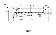
- another disclosed lighting assembly 14" includes a pyramid prism 68 supported on the top 44 side of the diffuser 42.
- the pyramid prism 68 is disposed near bright spots.
- the bright spots can be caused by a close proximity to the light source 20 or other optical characteristics of a specific configuration.
- the pyramid prism 68 disperses the light to compensate for bright spots and provide a more uniform distribution of light 60 directed to the display 56.
- a plurality of pyramid prisms 68 are disposed on the top surface 44 of the diffuser 42 proximate to the light source 20 and may also be disposed in other locations along the diffuser 42 where bright spots require further diffusion to provide a substantially uniform light distribution along the entire length of the diffuser 46.
- another lighting assembly 14"' includes a light guide 64 that includes a light receiving surface 66 disposed substantially parallel to the opening 18 in the light housing 16.
- the example light guide 64 curves from the light receiving surface 66 into a body portion 70 that extends transversely toward a terminal end. A width of the light guide 64 decreases in a direction away from the light receiving surface 66.
- the light receiving surface 66 is mated to a location of each of a plurality of light sources 20 and comprises a round surface that is positioned over a corresponding one of the light sources 20.
- Each of the round light receiving surfaces 66 is part of a wavy portion 72 that curves into and forms a uniform surface that tapers toward the terminal end.
- the wavy light receiving surface 66 tapers into the bend portion 72 to provide a thickness modulation at the point where light enters the light guide 62 that further increases light efficiency.
- the disclosed lighting assemblies 14 provide a much more efficient transmission of light that increases luminance and enables the use of less or smaller light sources to generate the same or more light for illuminating displays an instrument panels.
Landscapes
- Physics & Mathematics (AREA)
- General Physics & Mathematics (AREA)
- Optics & Photonics (AREA)
- Instrument Panels (AREA)
- Planar Illumination Modules (AREA)
- Details Of Measuring Devices (AREA)
- Illuminated Signs And Luminous Advertising (AREA)
- Light Guides In General And Applications Therefor (AREA)
- Liquid Crystal (AREA)
Applications Claiming Priority (3)
| Application Number | Priority Date | Filing Date | Title |
|---|---|---|---|
| US201361884173P | 2013-09-30 | 2013-09-30 | |
| US201361884225P | 2013-09-30 | 2013-09-30 | |
| US14/495,343 US10101519B2 (en) | 2013-09-30 | 2014-09-24 | Lighting assembly for display illumination |
Publications (2)
| Publication Number | Publication Date |
|---|---|
| EP2853810A2 true EP2853810A2 (de) | 2015-04-01 |
| EP2853810A3 EP2853810A3 (de) | 2015-07-01 |
Family
ID=51659490
Family Applications (1)
| Application Number | Title | Priority Date | Filing Date |
|---|---|---|---|
| EP14186438.9A Withdrawn EP2853810A3 (de) | 2013-09-30 | 2014-09-25 | Beleuchtungseinrichtung zur Beleuchtung einer Anzeige |
Country Status (3)
| Country | Link |
|---|---|
| US (1) | US10101519B2 (de) |
| EP (1) | EP2853810A3 (de) |
| JP (1) | JP5943979B2 (de) |
Cited By (2)
| Publication number | Priority date | Publication date | Assignee | Title |
|---|---|---|---|---|
| CN108761625A (zh) * | 2018-05-11 | 2018-11-06 | 深圳市帝显电子有限公司 | 一种导光板及背光模组 |
| CN109424923A (zh) * | 2017-08-22 | 2019-03-05 | 伟瑞柯照明系统有限公司 | 一种机动车照明装置 |
Families Citing this family (6)
| Publication number | Priority date | Publication date | Assignee | Title |
|---|---|---|---|---|
| KR960006583B1 (ko) | 1992-05-25 | 1996-05-20 | 십닙폰세이테쭈 카부시키가이샤 | 강대의 연속소둔설비 |
| CN107924030A (zh) * | 2015-08-26 | 2018-04-17 | 3M创新有限公司 | 准直光导 |
| US10890468B2 (en) | 2017-02-02 | 2021-01-12 | Rebo Lighting & Electronics, Llc | Light ring assembly and method of using the same |
| WO2019037803A1 (en) * | 2017-08-22 | 2019-02-28 | Varroc Lighting Systems, s.r.o. | LUMINOUS DEVICE OF A MOTOR VEHICLE |
| JP7108839B2 (ja) * | 2018-05-30 | 2022-07-29 | パナソニックIpマネジメント株式会社 | 表示装置 |
| JP6972283B1 (ja) * | 2020-11-25 | 2021-11-24 | シャープ株式会社 | 収容庫の照明装置および収容庫 |
Citations (1)
| Publication number | Priority date | Publication date | Assignee | Title |
|---|---|---|---|---|
| US20040085749A1 (en) * | 1999-02-23 | 2004-05-06 | Parker Jeffery R. | Transreflectors, transreflector systems and displays and methods of making transreflectors |
Family Cites Families (22)
| Publication number | Priority date | Publication date | Assignee | Title |
|---|---|---|---|---|
| JP3821849B2 (ja) | 1995-08-23 | 2006-09-13 | コーニンクレッカ フィリップス エレクトロニクス エヌ ヴィ | フラットパネル画像表示装置用照明装置 |
| JP2000090719A (ja) | 1998-09-14 | 2000-03-31 | Casio Comput Co Ltd | 面光源装置 |
| CN1126900C (zh) | 1998-04-30 | 2003-11-05 | 卡西欧计算机株式会社 | 使用外界光和照明板的显示装置 |
| JP2000105542A (ja) | 1998-09-29 | 2000-04-11 | Casio Comput Co Ltd | 表示装置 |
| US6724535B1 (en) | 1998-12-31 | 2004-04-20 | Microsharp Corporation Limited | Stepped surface diffuser |
| FI107085B (fi) | 1999-05-28 | 2001-05-31 | Ics Intelligent Control System | Valopaneeli |
| WO2001044716A1 (en) | 1999-12-02 | 2001-06-21 | Reflexite Corporation | Asymmetric alternating prism arrays |
| JP2001222906A (ja) * | 2000-02-08 | 2001-08-17 | Minebea Co Ltd | 面状照明装置 |
| JP3301752B2 (ja) * | 2000-03-31 | 2002-07-15 | 三菱電機株式会社 | フロントライト、反射型液晶表示装置および携帯情報端末 |
| JP2002203411A (ja) | 2000-12-27 | 2002-07-19 | Casio Comput Co Ltd | 面光源およびそれを用いた液晶表示装置 |
| US6576887B2 (en) | 2001-08-15 | 2003-06-10 | 3M Innovative Properties Company | Light guide for use with backlit display |
| JP2004106662A (ja) | 2002-09-17 | 2004-04-08 | Denso Corp | 車両用表示装置 |
| JP2004119143A (ja) | 2002-09-25 | 2004-04-15 | Casio Comput Co Ltd | 面光源 |
| JP2005165199A (ja) | 2003-12-05 | 2005-06-23 | Alps Electric Co Ltd | プリズムシート及び照光装置及び面発光装置並びに液晶表示装置 |
| TWI240831B (en) | 2004-01-20 | 2005-10-01 | Ace T Corp | Small-angle light-emitting device at specific positions for back light module of liquid crystal display |
| US7607808B2 (en) | 2004-06-16 | 2009-10-27 | Continental Automotive Systems Us, Inc. | Instrument panel housing with light diffuser |
| JP2007127871A (ja) | 2005-11-04 | 2007-05-24 | Alps Electric Co Ltd | 立体表示装置 |
| US7593615B2 (en) | 2006-02-10 | 2009-09-22 | Rpc Photonics, Inc. | Optical devices for guiding illumination |
| KR101263502B1 (ko) | 2006-03-27 | 2013-05-13 | 엘지디스플레이 주식회사 | 엘이디 백라이트 유닛 및 이를 구비한 액정표시장치 |
| JP2011145612A (ja) | 2010-01-18 | 2011-07-28 | Dainippon Printing Co Ltd | 光学シート、面光源装置、及び透過型表示装置 |
| TW201305487A (zh) * | 2011-07-13 | 2013-02-01 | Rambus Inc | 具有被控制之可配置的光改向之照明組件 |
| JP2013187059A (ja) | 2012-03-08 | 2013-09-19 | Hitachi Chemical Co Ltd | 導光板及び面光源装置 |
-
2014
- 2014-09-24 US US14/495,343 patent/US10101519B2/en active Active
- 2014-09-25 EP EP14186438.9A patent/EP2853810A3/de not_active Withdrawn
- 2014-09-30 JP JP2014201031A patent/JP5943979B2/ja active Active
Patent Citations (1)
| Publication number | Priority date | Publication date | Assignee | Title |
|---|---|---|---|---|
| US20040085749A1 (en) * | 1999-02-23 | 2004-05-06 | Parker Jeffery R. | Transreflectors, transreflector systems and displays and methods of making transreflectors |
Cited By (2)
| Publication number | Priority date | Publication date | Assignee | Title |
|---|---|---|---|---|
| CN109424923A (zh) * | 2017-08-22 | 2019-03-05 | 伟瑞柯照明系统有限公司 | 一种机动车照明装置 |
| CN108761625A (zh) * | 2018-05-11 | 2018-11-06 | 深圳市帝显电子有限公司 | 一种导光板及背光模组 |
Also Published As
| Publication number | Publication date |
|---|---|
| JP2015109261A (ja) | 2015-06-11 |
| JP5943979B2 (ja) | 2016-07-05 |
| US10101519B2 (en) | 2018-10-16 |
| EP2853810A3 (de) | 2015-07-01 |
| US20150092390A1 (en) | 2015-04-02 |
Similar Documents
| Publication | Publication Date | Title |
|---|---|---|
| EP2853810A2 (de) | Beleuchtungseinrichtung zur Beleuchtung einer Anzeige | |
| US9328885B2 (en) | Vehicle lighting unit | |
| US7172324B2 (en) | Internally illuminated light panel with LED modules having light redirecting devices | |
| US9891371B2 (en) | Light guide illumination device for direct-indirect illumination | |
| US8434892B2 (en) | Collimator assembly | |
| US8129731B2 (en) | Light emitting diode lighting device | |
| EP4073424B1 (de) | Leuchte mit lichtleiter für ein fahrzeug | |
| CN101329423A (zh) | 导光板及背光模组 | |
| US20080084708A1 (en) | Linear light source using point light source | |
| US20060109684A1 (en) | Backlight unit | |
| JP2006269364A (ja) | Led面光源装置 | |
| WO2013035788A1 (ja) | 照明装置および照明スタンド | |
| WO2008077338A1 (en) | Light-emitting devices and lens therefor | |
| CN102483215A (zh) | 带嵌入式光源的光导 | |
| US20070274103A1 (en) | Light guide panel and a backlight unit using the same | |
| JP2005228700A (ja) | 照明装置及びそれを備える表示装置 | |
| TWI410681B (zh) | 液晶顯示器及其導光板 | |
| CN104456347B (zh) | 用于车辆的照明装置 | |
| US20120294029A1 (en) | Backlight and display device with the backlight | |
| EP2241799B1 (de) | Anzeigeanordnung mit Lichtröhre mit zentralem Raum für Lichtquelle | |
| JP2005085580A (ja) | 面照明装置及び導光板 | |
| EP2132480A2 (de) | Allgemeines beleuchtungssystem und leuchtkörper | |
| JP5711893B2 (ja) | 面光源装置 | |
| KR101502047B1 (ko) | 엘이디 평판조명모듈 | |
| US20200348566A1 (en) | Light bundle control member, light emitting device, area-light source device, and display device |
Legal Events
| Date | Code | Title | Description |
|---|---|---|---|
| PUAI | Public reference made under article 153(3) epc to a published international application that has entered the european phase |
Free format text: ORIGINAL CODE: 0009012 |
|
| 17P | Request for examination filed |
Effective date: 20140925 |
|
| AK | Designated contracting states |
Kind code of ref document: A2 Designated state(s): AL AT BE BG CH CY CZ DE DK EE ES FI FR GB GR HR HU IE IS IT LI LT LU LV MC MK MT NL NO PL PT RO RS SE SI SK SM TR |
|
| AX | Request for extension of the european patent |
Extension state: BA ME |
|
| PUAL | Search report despatched |
Free format text: ORIGINAL CODE: 0009013 |
|
| AK | Designated contracting states |
Kind code of ref document: A3 Designated state(s): AL AT BE BG CH CY CZ DE DK EE ES FI FR GB GR HR HU IE IS IT LI LT LU LV MC MK MT NL NO PL PT RO RS SE SI SK SM TR |
|
| AX | Request for extension of the european patent |
Extension state: BA ME |
|
| RIC1 | Information provided on ipc code assigned before grant |
Ipc: F21V 8/00 20060101AFI20150527BHEP Ipc: G02B 6/00 20060101ALI20150527BHEP |
|
| R17P | Request for examination filed (corrected) |
Effective date: 20151109 |
|
| RBV | Designated contracting states (corrected) |
Designated state(s): AL AT BE BG CH CY CZ DE DK EE ES FI FR GB GR HR HU IE IS IT LI LT LU LV MC MK MT NL NO PL PT RO RS SE SI SK SM TR |
|
| RIN1 | Information on inventor provided before grant (corrected) |
Inventor name: SANDERS, RICHARD DANIEL Inventor name: BIRMAN, VYACHESLAV BORISOVICH |
|
| STAA | Information on the status of an ep patent application or granted ep patent |
Free format text: STATUS: EXAMINATION IS IN PROGRESS |
|
| 17Q | First examination report despatched |
Effective date: 20190626 |
|
| RAP1 | Party data changed (applicant data changed or rights of an application transferred) |
Owner name: CONTINENTAL AUTOMOTIVE SYSTEMS, INC. |
|
| STAA | Information on the status of an ep patent application or granted ep patent |
Free format text: STATUS: THE APPLICATION IS DEEMED TO BE WITHDRAWN |
|
| 18D | Application deemed to be withdrawn |
Effective date: 20211008 |