EP2853763B1 - Axle shaft and assembly - Google Patents
Axle shaft and assembly Download PDFInfo
- Publication number
- EP2853763B1 EP2853763B1 EP14186561.8A EP14186561A EP2853763B1 EP 2853763 B1 EP2853763 B1 EP 2853763B1 EP 14186561 A EP14186561 A EP 14186561A EP 2853763 B1 EP2853763 B1 EP 2853763B1
- Authority
- EP
- European Patent Office
- Prior art keywords
- axle shaft
- drive
- drive finger
- shaft
- finger
- Prior art date
- Legal status (The legal status is an assumption and is not a legal conclusion. Google has not performed a legal analysis and makes no representation as to the accuracy of the status listed.)
- Active
Links
- 238000000034 method Methods 0.000 claims description 17
- 230000035939 shock Effects 0.000 claims description 13
- 239000007787 solid Substances 0.000 claims description 13
- 239000006096 absorbing agent Substances 0.000 claims description 12
- 238000005520 cutting process Methods 0.000 description 7
- 229910000831 Steel Inorganic materials 0.000 description 5
- 239000010959 steel Substances 0.000 description 5
- 238000003754 machining Methods 0.000 description 4
- 238000005096 rolling process Methods 0.000 description 4
- 238000005452 bending Methods 0.000 description 3
- 239000000463 material Substances 0.000 description 3
- 238000004519 manufacturing process Methods 0.000 description 2
- 238000007789 sealing Methods 0.000 description 2
- 238000003466 welding Methods 0.000 description 2
- 230000005540 biological transmission Effects 0.000 description 1
- 238000005255 carburizing Methods 0.000 description 1
- 238000010276 construction Methods 0.000 description 1
- 238000005242 forging Methods 0.000 description 1
- 230000006698 induction Effects 0.000 description 1
- 238000003780 insertion Methods 0.000 description 1
- 230000037431 insertion Effects 0.000 description 1
- 239000000314 lubricant Substances 0.000 description 1
- 230000014759 maintenance of location Effects 0.000 description 1
- 239000002184 metal Substances 0.000 description 1
- 238000010791 quenching Methods 0.000 description 1
- 230000000171 quenching effect Effects 0.000 description 1
Images


Classifications
-
- B—PERFORMING OPERATIONS; TRANSPORTING
- B60—VEHICLES IN GENERAL
- B60B—VEHICLE WHEELS; CASTORS; AXLES FOR WHEELS OR CASTORS; INCREASING WHEEL ADHESION
- B60B35/00—Axle units; Parts thereof ; Arrangements for lubrication of axles
- B60B35/12—Torque-transmitting axles
-
- B—PERFORMING OPERATIONS; TRANSPORTING
- B60—VEHICLES IN GENERAL
- B60B—VEHICLE WHEELS; CASTORS; AXLES FOR WHEELS OR CASTORS; INCREASING WHEEL ADHESION
- B60B27/00—Hubs
- B60B27/06—Hubs adapted to be fixed on axle
-
- B—PERFORMING OPERATIONS; TRANSPORTING
- B60—VEHICLES IN GENERAL
- B60B—VEHICLE WHEELS; CASTORS; AXLES FOR WHEELS OR CASTORS; INCREASING WHEEL ADHESION
- B60B27/00—Hubs
- B60B27/06—Hubs adapted to be fixed on axle
- B60B27/065—Hubs adapted to be fixed on axle characterised by the fixation of the hub to the axle
-
- F—MECHANICAL ENGINEERING; LIGHTING; HEATING; WEAPONS; BLASTING
- F16—ENGINEERING ELEMENTS AND UNITS; GENERAL MEASURES FOR PRODUCING AND MAINTAINING EFFECTIVE FUNCTIONING OF MACHINES OR INSTALLATIONS; THERMAL INSULATION IN GENERAL
- F16D—COUPLINGS FOR TRANSMITTING ROTATION; CLUTCHES; BRAKES
- F16D1/00—Couplings for rigidly connecting two coaxial shafts or other movable machine elements
- F16D1/10—Quick-acting couplings in which the parts are connected by simply bringing them together axially
- F16D1/108—Quick-acting couplings in which the parts are connected by simply bringing them together axially having retaining means rotating with the coupling and acting by interengaging parts, i.e. positive coupling
-
- B—PERFORMING OPERATIONS; TRANSPORTING
- B60—VEHICLES IN GENERAL
- B60B—VEHICLE WHEELS; CASTORS; AXLES FOR WHEELS OR CASTORS; INCREASING WHEEL ADHESION
- B60B2360/00—Materials; Physical forms thereof
- B60B2360/10—Metallic materials
- B60B2360/102—Steel
-
- B—PERFORMING OPERATIONS; TRANSPORTING
- B60—VEHICLES IN GENERAL
- B60B—VEHICLE WHEELS; CASTORS; AXLES FOR WHEELS OR CASTORS; INCREASING WHEEL ADHESION
- B60B2360/00—Materials; Physical forms thereof
- B60B2360/14—Physical forms of metallic parts
- B60B2360/143—Bars, i.e. being solid
-
- B—PERFORMING OPERATIONS; TRANSPORTING
- B60—VEHICLES IN GENERAL
- B60B—VEHICLE WHEELS; CASTORS; AXLES FOR WHEELS OR CASTORS; INCREASING WHEEL ADHESION
- B60B2360/00—Materials; Physical forms thereof
- B60B2360/14—Physical forms of metallic parts
- B60B2360/144—Tubes, i.e. being hollow
- B60B2360/1442—Tubes, i.e. being hollow of circular cross section
-
- B—PERFORMING OPERATIONS; TRANSPORTING
- B60—VEHICLES IN GENERAL
- B60B—VEHICLE WHEELS; CASTORS; AXLES FOR WHEELS OR CASTORS; INCREASING WHEEL ADHESION
- B60B2900/00—Purpose of invention
- B60B2900/10—Reduction of
- B60B2900/112—Costs
-
- B—PERFORMING OPERATIONS; TRANSPORTING
- B60—VEHICLES IN GENERAL
- B60B—VEHICLE WHEELS; CASTORS; AXLES FOR WHEELS OR CASTORS; INCREASING WHEEL ADHESION
- B60B2900/00—Purpose of invention
- B60B2900/30—Increase in
- B60B2900/311—Rigidity or stiffness
-
- B—PERFORMING OPERATIONS; TRANSPORTING
- B60—VEHICLES IN GENERAL
- B60Y—INDEXING SCHEME RELATING TO ASPECTS CROSS-CUTTING VEHICLE TECHNOLOGY
- B60Y2200/00—Type of vehicle
- B60Y2200/10—Road Vehicles
-
- F—MECHANICAL ENGINEERING; LIGHTING; HEATING; WEAPONS; BLASTING
- F16—ENGINEERING ELEMENTS AND UNITS; GENERAL MEASURES FOR PRODUCING AND MAINTAINING EFFECTIVE FUNCTIONING OF MACHINES OR INSTALLATIONS; THERMAL INSULATION IN GENERAL
- F16D—COUPLINGS FOR TRANSMITTING ROTATION; CLUTCHES; BRAKES
- F16D1/00—Couplings for rigidly connecting two coaxial shafts or other movable machine elements
- F16D1/10—Quick-acting couplings in which the parts are connected by simply bringing them together axially
- F16D2001/102—Quick-acting couplings in which the parts are connected by simply bringing them together axially the torque is transmitted via polygon shaped connections
Definitions
- This invention relates in general to vehicle axles and more particularly to wheel drive axles.
- Axle shafts are used to connect a driving and a driven member, such as the differential of an automotive vehicle and a driven wheel.
- Axle shafts particularly for automotive vehicles, typically are formed of solid metal shafts with their opposite ends formed for connecting to the drive and driven members of the vehicle.
- a flange may be forged or welded onto one end of the shaft for connection to a wheel hub, while the opposite end of the shaft may be provided with a spline for connection to a differential gear. Because such shafts must transmit considerable torque and are subjected to rapid starts and stops of power transmission, they must be rigid and strong enough to perform under both normal and overload conditions.
- axle shafts are formed from solid steel bar or rod to provide the required strength and rigidity.
- hollow axle shafts have been used in the past with a wheel driving flange friction welded to the outer or wheel end of the shaft and a spline provided on the opposite end by a cutting, broaching or similar process.
- a wheel driving flange friction welded to the outer or wheel end of the shaft and a spline provided on the opposite end by a cutting, broaching or similar process.
- Wheel driving flanges have been connected to hollow shafts through splines, but these designs have been complicated and not viable due to the structural problems in strength and rigidity and maintaining the axial position of the wheel driving flange.
- This invention relates an axle shaft having a radially outwardly extending drive finger or fingers which are configured to drivingly engage a wheel hub.
- the wheel hub includes a rigidly secured hub cover having drive slots which drivingly engage the drive fingers.
- a shock absorber may be positioned between the drive fingers and the drive slots.
- the hub cover may also maintain the axial position of the shaft.
- the axle shaft may be formed from a hollow tube or a solid shaft by cutting an end and bending a cut section radially outwardly to form a drive finger.
- a drive finger In a preferred embodiment, four equally circumferentially spaced drive fingers are formed.
- a typical prior art vehicle axle shaft 10 is formed from a solid steel bar or rod 12.
- the shaft 12 has a spline end portion 22.
- Splines 24 typically are formed through a cutting or rolling process.
- the splines drivingly engage a differential gear of a vehicle.
- An annular groove 23 is provided to accept a clip for axial retention of the shaft 12 within a differential gear.
- a wheel drive flange 14 is provided on the opposite end portion of the shaft 12.
- the flange 12 may be forged onto the end of the shaft or attached through a process such as friction welding.
- the flange 14 includes bolt holes 16 to facilitate attachment of the shaft to a wheel hub.
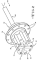
- FIG. 2 shows a wheel end assembly 30 utilizing the present invention.
- the assembly 30 includes a wheel hub 32.
- An axle shaft 60 extends along a longitudinal or rotational axis A through the hub 32.
- the hub 32 includes a wheel mounting plate 34 having threaded bolt holes 36 for attaching a vehicle wheel.
- a hub housing 38 contains bearings and lubricant, as is well known in the art.
- the hub housing 38 has an open end 39 which is sealed by a hub cover 50.
- the hub cover 50 drivingly engages drive fingers 70 on the axle shaft as will be explained in detail below.
- the housing 38 has eight axially extending threaded holes 42.
- Eight bolts 41 extend through eight bolt holes 52 in the cover 50 and are threaded into the eight threaded bolt holes 42 to secure the cover 50 to the housing 38.
- the number of bolts 41 may vary according to the vehicle and axle designs.
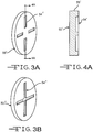
- the hub cover 50 has an axially inner surface 53 which sealingly engages the hub housing 38 near the outer periphery of the hub.
- the inner surface 53 defines four radially extending drive slots 54.
- the drive slots 54 may be forged or cut inot the hub cover 50.
- the drive slots 54 are equally circumferentially spaced about the inner surface 53.
- Each drive slot 54 has a bottom surface 56 for engagement with an outer surface of a drive finger 70 and two opposed and radially extending drive surfaces 58 for engagement with corresponding drive surfaces of the drive finger as will be explained below.
- the slots 54 extend from a radially inner wall 59 near the center of the hub cover 50 to the outer periphery 55.
- the drive slots 54' extend radially outwardly a length short of the outer periphery 55' of the hub cover 50'. Such a design may in some applications allow the hub housing 38 to be more readily sealed by the hub cover 50'.
- FIG 3B for easier fabrication, it may be desirable to eliminate the inner walls 59 by extending diametrically opposed or coaxial slots into each other. In other words, slots 54" extend completely across the inner surface of the hub cover 50", creating two intersecting slots 54", each of which would engage two drive fingers 70. A gasket or O-ring may be provided between the hub cover and the hub for sealing.
- an unhardened hollow shaft or tube 60 has a longitudinal or rotational axis A.
- the shaft 60 preferably is formed from AISI 1541 or similar steel, but may be formed from any suitable material, such as ionconel, for example.
- One end portion of the tube 60 is provided with a spline (not shown) for connection to a differential gear.
- the spline may be formed in any conventional manner.
- the opposite end portion of the tube 60 has four equally circumferentially spaced slots 62.
- the slots may be cut into the tube 60 in any conventional manner, such as with a cutting tool, a laser, etc.
- the slots 62 define cut segments 69 which will form the drive fingers 70.
- the cut segments 69 are bent radially outwardly approximately 90 degrees into an upright position relative to the shaft axis A.
- the bending may be done by any suitable process, such as rolling, as will be apparent to those skilled in the art.
- the disclosed embodiment has four cut segments 69 and drive fingers 70, but any number of fingers may be used, depending on the vehicle application, torque, speed, shock load requirements, etc.
- each drive finger 70 having a radially extending and axially facing inner surface 72 which has the curvature of the outer surface of the tube 60, and a radially extending and axially facing outer surface 74 which has the curvature of the inner surface of the tube 60.
- Each drive finger 70 will have opposed radially extending and generally circumferentially facing drive surfaces 76.
- the drive surfaces 76 are the surfaces of the tube where the cuts were made.
- Drive surfaces 76 are planar or flat but are oriented at an oblique angle transverse to the shaft axis A.
- the drive surfaces 76 of each drive finger 70 could be further deformed or cut to be parallel with each other if desired for any particular application.
- Hardening may or may not be required or desirable after the fingers 70 are formed into a near final shape. If required or desired, hardening may be accomplished by any known process such as induction hardening or carburization. A final machining step may be required to give the fingers 70 a final shape.
- each drive finger 70 is positioned in a corresponding drive slot 54 of the hub cover 50.
- An optional shock absorber 80 is provided between each drive finger drive surface 76 and the corresponding hub cover slot drive surface 58.
- the shock absorber 80 is an elastomeric member molded to or adhered to the drive finger drive surface 76.
- the shock absorber 80 may also be molded into or adhered to the hub cover drive surface 58.
- the shock absorber 80 may have any size or shape as required for any particular application.
- the shock absorber 80 may extend completely around the finger 70 and extend the complete length of the finger 70.
- the shock absorber may completely line the hub cover slot 54.
- other types of shock absorbers may be used, such as a spring.
- each drive finger 70 When the hub cover 50 is assembled onto the hub 32, the outer surface 74 of each drive finger 70 is in contact with the bottom surface 56 of the corresponding drive slot 54 and the inner surface 72 of each drive finger 70 is in contact with the outer surface 39 of the hub housing 38.
- the drive fingers 70, and therefore the axle shaft 60, thereby are held in an axial position by the hub cover 50 and hub housing 38.
- the drive fingers 70 are not directly bolted to the hub cover or hub housing and therefore have no bolt apertures.
- Figure 8 shows an alternative axle shaft 60' formed form a hollow shaft.
- the initial rolling process used to bend the drive fingers 70' radially outwardly leaves each drive finger in a curved configuration.
- a secondary straightening process is utilized to form the radially outward tips 71' of each drive finger into the cross-sectional shape of the drive fingers 70 shown in Figure 7 , with flat axially facing inner 72' and outer 74' surfaces.
- Drive surfaces 76' may extend at an oblique angle relative to the shaft axial A, or may be deformed or machined to be parallel to each other. It may not be necessary to straighten the entire drive finger 70', leaving a curved intermediate section 78' positioned readily inwardly of the drive finger tips 71'.
- the hub cover slots would have to accommodate the additional axial depth of the intermediate curved portion 78'.
- Figure 9 shows an alternative embodiment of the present invention in which an axle shaft 100 is formed from an unhardened bar or rod of AISI 1541 steel or any other suitable material.
- One end portion of the shaft 100 is provided with a spline 91 for connection to a differential gear.
- the spline may be formed in any conventional manner.
- the opposite end portion of the shaft 100 is provided with four radially extending and equally circumferentially spaced drive fingers 90.
- the drive fingers 90 are formed utilizing a forging process in which the solid rod or bar is forged into a near net configuration with integral drive fingers 90 at one end.
- a machining operation may be required to give the fingers 90 a desired final shape.
- the shaft may be hardened using any known process.
- a final machining step may be required after hardening to give the fingers 90 a final shape after hardening. It is preferred for this embodiment that the radially extending drive surfaces 96 are parallel to each other and perpendicular to the shaft axis A'.
- Figure 9A shows an alternative embodiment of the hub cover 150' in which the drive slots do not extend to the periphery radially outer periphery. This allows for better hub cover contact with the gasket 151.
- an O-ring or other sealing device may be used.
- the hub cover 150 has drive slots 154 for drivingly engaging the drive fingers 90. Because the drive fingers 90 have been forged, the drive slots 154 are essentially joined into a single channel in the hub cover surface 153, the channel having four radially extending grooves to match the configuration of the drive fingers 90.
- the hub cover 50' has a scalloped outer periphery to match the scalloped shape of the hub housing and to reduce weight and material.
- FIG 10 shows an enlarged view of the shaft 100 with the drive fingers 90 drivingly engaged with the hub cover 150.
- a shock absorber 110 in the form of an elastomeric bushing is positioned between the drive fingers 90 and the drive surfaces of the hub cover slots 154.
- the bushing 110 is a one-piece molded unit which is inserted into the slots 154 prior to insertion of the drive fingers 90.
- the bushing 110 can be molded or adhered to the drive fingers 90 or to the hub cover slots 154.
- alternative shock absorbers may be used as well, such as springs.
- FIG 11 shows an alternative method of making an axle shaft of the present invention.
- Axle shaft 120 is formed from an unhardened bar of rod of AISI 1541 or similar steel.
- An end of the shaft has four equally circumferentially spaced slots 122.
- the slots may be cut in any conventional manner, such as with a cutting tool, a laser, etc.
- the slots 122 define four drive fingers 124. After cutting, the fingers 124 are bent radially outwardly into an upright position 90 degrees from the shaft axis A. Bending may be done by any suitable process, such as rolling, as will be apparent to those skilled in the art.
- the fingers 124 are then deformed into a desired cross-sectional shape, such as a rectangular shape or a trapezoidal shape similar to that of the drive finger 70 of Figure 7 .
- the shaft is hardening through a carburizing and quenching process as is well known in the art.
- a final machining step may be required after hardening to give the fingers 124 a final shape.
- a conventional solid axle for such an application has an outer diameter of about 1.87 inches and a length of about 40 inches.
- a typical hub has an outer diameter of about 8.5 inches.
- a hollow axle 60 having an outer diameter of about 1.95 and an inner diameter of about 1.14 inches would provide comparable strength and rigidity.
- the axial thickness of each drive finger 70 would be approximately 0.40 inches, with a hub cover thickness of about 0.8 inches.
- a solid shaft axle 100, 120 of the present invention having comparable strength and rigidity could be made having the same approximately 1.87 inch outer diameter.
- the hub cover diameter would be about 8.5 inches, with the drive fingers extending radially outwardly approximately 3 inches from the outer surface of the shaft.
- the radial length of the drive fingers is at least 10% of the maximum outer surface diameter of the shaft from which it extends.
Landscapes
- Engineering & Computer Science (AREA)
- Mechanical Engineering (AREA)
- General Engineering & Computer Science (AREA)
- Shafts, Cranks, Connecting Bars, And Related Bearings (AREA)
- Motor Power Transmission Devices (AREA)
- Vehicle Body Suspensions (AREA)
- Axle Suspensions And Sidecars For Cycles (AREA)
Applications Claiming Priority (1)
| Application Number | Priority Date | Filing Date | Title |
|---|---|---|---|
| US14/037,426 US9296258B2 (en) | 2013-09-26 | 2013-09-26 | Axle shaft and assembly |
Publications (2)
| Publication Number | Publication Date |
|---|---|
| EP2853763A1 EP2853763A1 (en) | 2015-04-01 |
| EP2853763B1 true EP2853763B1 (en) | 2017-03-29 |
Family
ID=51660324
Family Applications (1)
| Application Number | Title | Priority Date | Filing Date |
|---|---|---|---|
| EP14186561.8A Active EP2853763B1 (en) | 2013-09-26 | 2014-09-26 | Axle shaft and assembly |
Country Status (6)
| Country | Link |
|---|---|
| US (1) | US9296258B2 (zh) |
| EP (1) | EP2853763B1 (zh) |
| CN (1) | CN104669937B (zh) |
| BR (1) | BR102014023604B1 (zh) |
| CA (1) | CA2870327C (zh) |
| MX (1) | MX353803B (zh) |
Families Citing this family (3)
| Publication number | Priority date | Publication date | Assignee | Title |
|---|---|---|---|---|
| CN113251062A (zh) * | 2021-05-28 | 2021-08-13 | 山东创新板材有限公司 | 一种驱动运行装置及安装方法 |
| CN113682087B (zh) * | 2021-08-30 | 2024-01-09 | 一汽解放汽车有限公司 | 一种驱动桥的扭矩输入结构及贯通驱动桥 |
| CN114312144B (zh) * | 2022-01-07 | 2023-08-18 | 吉林大学 | 双转子电机耦合圆柱差速器左右半轴的多模式电动驱动桥 |
Family Cites Families (28)
| Publication number | Priority date | Publication date | Assignee | Title |
|---|---|---|---|---|
| US2455216A (en) * | 1945-12-04 | 1948-11-30 | Ray E Blanton | Vehicle wheel mounting |
| US2439012A (en) * | 1947-03-14 | 1948-04-06 | Hershel B Ledford | Wheel and axle construction |
| US3017207A (en) * | 1958-01-20 | 1962-01-16 | Cutlas Tool And Mfg Company | Vehicle hub construction |
| CA1074668A (en) | 1977-03-21 | 1980-04-01 | Tamco Limited | Steering shaft and flange and method of making same |
| US4266646A (en) | 1978-11-06 | 1981-05-12 | Warn Industries, Inc. | Wheel stud mounted locking clutch |
| FR2628488B1 (fr) | 1988-03-14 | 1990-12-28 | Ecia Equip Composants Ind Auto | Attache rapide du type a baionnette perfectionnee |
| US5005913A (en) | 1988-08-25 | 1991-04-09 | Deere & Company | Wheel tread adjusting device |
| US5213250A (en) | 1991-12-19 | 1993-05-25 | Simon Joseph A | Method for forming a lightweight flanged axle shaft |
| US5222786A (en) * | 1992-01-10 | 1993-06-29 | Royal Appliance Mfg. Co. | Wheel construction for vacuum cleaner |
| DE19625343C1 (de) | 1996-06-25 | 1997-09-04 | Daimler Benz Ag | Radlagerung einer angetriebenen Achse mit einem hohlen, die Radlasten aufnehmenden Achskörper |
| US6059378A (en) | 1997-05-01 | 2000-05-09 | Impact Forge, Inc. | Taperlock axle apparatus and flange |
| US6065893A (en) * | 1998-07-31 | 2000-05-23 | Montanez, Jr.; Sixto | Lockable wheel assembly |
| US6099083A (en) | 1998-10-23 | 2000-08-08 | Graco Children's Products Inc. | Retention mechanism for use with an axle assembly |
| FR2794063B1 (fr) * | 1999-05-28 | 2001-07-27 | Mavic Sa | Moyeu de roue de bicyclette prevu pour etre equipe d'un disque de freinage |
| US6254196B1 (en) | 1999-12-21 | 2001-07-03 | Thomas A Gee | Axle hub assembly with removable axle shaft |
| US6467853B1 (en) | 2000-08-09 | 2002-10-22 | Deere & Company | Keyed anti-wear thrust washer structure |
| US6572199B1 (en) * | 2002-04-03 | 2003-06-03 | General Motors Corporation | Flanged tubular axle shaft assembly |
| US6802570B2 (en) * | 2002-09-27 | 2004-10-12 | Load Rite Trailers, Inc. | Oriented roller bushing for boat trailer |
| US6948782B2 (en) | 2003-05-21 | 2005-09-27 | The Toro Company | Wheel hub assemblies with anti-rotate feature for use with zero-radius-turning vehicle |
| EP1629998B1 (en) * | 2004-08-26 | 2008-01-09 | Chin Haur Industry Co., Ltd. | Rear hub assembly for a bicycle |
| DE102004061774B3 (de) | 2004-12-22 | 2006-04-27 | Aktiebolaget Skf | Radlager |
| ITVR20070068A1 (it) * | 2007-05-09 | 2008-11-10 | Claudio Galvanin | Dispositivo di fissaggio di una ruota |
| US7699405B2 (en) | 2007-08-24 | 2010-04-20 | The Timken Company | Vehicle wheel end assemblies and methods of assembly thereof |
| JP2011520693A (ja) | 2008-05-19 | 2011-07-21 | ゲーカーエン ドライブライン ドイチュラント ゲーエムベーハー | ホイールハブ及び等速ロータリージョイントを備える装置 |
| DE102009038039A1 (de) | 2009-08-19 | 2011-02-24 | Bayerische Motoren Werke Aktiengesellschaft | Drehmomentübertragungseinrichtung |
| DE102011109705A1 (de) | 2011-08-06 | 2013-02-07 | Daimler Ag | Lenkungsanordnung |
| CN202451622U (zh) | 2012-03-14 | 2012-09-26 | 谭小兵 | 半轴和轮毂连接盘 |
| CN202641263U (zh) * | 2012-06-14 | 2013-01-02 | 广东富华工程机械制造有限公司 | 一种轴头结构 |
-
2013
- 2013-09-26 US US14/037,426 patent/US9296258B2/en not_active Expired - Fee Related
-
2014
- 2014-09-23 CA CA2870327A patent/CA2870327C/en active Active
- 2014-09-23 BR BR102014023604-0A patent/BR102014023604B1/pt active IP Right Grant
- 2014-09-24 MX MX2014011462A patent/MX353803B/es active IP Right Grant
- 2014-09-26 CN CN201410500268.1A patent/CN104669937B/zh active Active
- 2014-09-26 EP EP14186561.8A patent/EP2853763B1/en active Active
Non-Patent Citations (1)
| Title |
|---|
| None * |
Also Published As
| Publication number | Publication date |
|---|---|
| BR102014023604B1 (pt) | 2020-12-01 |
| CN104669937A (zh) | 2015-06-03 |
| US9296258B2 (en) | 2016-03-29 |
| BR102014023604A2 (pt) | 2016-07-12 |
| CN104669937B (zh) | 2019-02-15 |
| MX353803B (es) | 2018-01-30 |
| MX2014011462A (es) | 2015-08-20 |
| US20150084399A1 (en) | 2015-03-26 |
| EP2853763A1 (en) | 2015-04-01 |
| CA2870327A1 (en) | 2015-03-26 |
| CA2870327C (en) | 2021-11-09 |
Similar Documents
| Publication | Publication Date | Title |
|---|---|---|
| US7695392B2 (en) | Differential mechanism assembly | |
| EP2781781B1 (en) | Clutch device | |
| US10473168B2 (en) | Ball retaining ball and ramp assembly | |
| US8544174B2 (en) | Differential mechanism having multiple case portions | |
| US6572199B1 (en) | Flanged tubular axle shaft assembly | |
| EP1586794A2 (en) | Differential with pinion bearings supported on input yoke | |
| US7485044B2 (en) | Shaft assembly and method of manufacture thereof | |
| EP2695686A1 (en) | An axle housing and a method of manufacture | |
| EP2853763B1 (en) | Axle shaft and assembly | |
| US9885413B2 (en) | Sliding sleeve for supporting sun gears | |
| US6659651B1 (en) | Driving and locking mechanism for a threaded bearing cup | |
| WO2014062613A1 (en) | Drive pinion fastening assembly | |
| EP0893613A1 (en) | Cardan shaft | |
| US20080247701A1 (en) | Bearing Unit Comprising a Sheet Metal Element | |
| EP3026274B1 (en) | Tunable torque transmitting shaft | |
| US6464058B2 (en) | Hub for a clutch | |
| EP2921320B1 (en) | Axle shaft | |
| US6904681B2 (en) | Method for fabricating a driving and locking mechanism | |
| EP3649358B1 (en) | Quick connect assembly and retaining member for use therein | |
| US20170356536A1 (en) | Lightweight and narrow differential assembly with powder metal inserts | |
| CN108071700A (zh) | 用于车辆的复合法兰 | |
| MX2014010582A (es) | Metodo para formar un eje impulsor y varilla de union integrados. |
Legal Events
| Date | Code | Title | Description |
|---|---|---|---|
| PUAI | Public reference made under article 153(3) epc to a published international application that has entered the european phase |
Free format text: ORIGINAL CODE: 0009012 |
|
| 17P | Request for examination filed |
Effective date: 20140926 |
|
| AK | Designated contracting states |
Kind code of ref document: A1 Designated state(s): AL AT BE BG CH CY CZ DE DK EE ES FI FR GB GR HR HU IE IS IT LI LT LU LV MC MK MT NL NO PL PT RO RS SE SI SK SM TR |
|
| AX | Request for extension of the european patent |
Extension state: BA ME |
|
| R17P | Request for examination filed (corrected) |
Effective date: 20150924 |
|
| RBV | Designated contracting states (corrected) |
Designated state(s): AL AT BE BG CH CY CZ DE DK EE ES FI FR GB GR HR HU IE IS IT LI LT LU LV MC MK MT NL NO PL PT RO RS SE SI SK SM TR |
|
| REG | Reference to a national code |
Ref country code: DE Ref legal event code: R079 Ref document number: 602014008027 Country of ref document: DE Free format text: PREVIOUS MAIN CLASS: F16D0001060000 Ipc: F16D0001100000 |
|
| RIC1 | Information provided on ipc code assigned before grant |
Ipc: F16D 1/10 20060101AFI20160707BHEP |
|
| GRAP | Despatch of communication of intention to grant a patent |
Free format text: ORIGINAL CODE: EPIDOSNIGR1 |
|
| INTG | Intention to grant announced |
Effective date: 20161025 |
|
| GRAS | Grant fee paid |
Free format text: ORIGINAL CODE: EPIDOSNIGR3 |
|
| GRAA | (expected) grant |
Free format text: ORIGINAL CODE: 0009210 |
|
| AK | Designated contracting states |
Kind code of ref document: B1 Designated state(s): AL AT BE BG CH CY CZ DE DK EE ES FI FR GB GR HR HU IE IS IT LI LT LU LV MC MK MT NL NO PL PT RO RS SE SI SK SM TR |
|
| REG | Reference to a national code |
Ref country code: GB Ref legal event code: FG4D |
|
| REG | Reference to a national code |
Ref country code: CH Ref legal event code: EP |
|
| REG | Reference to a national code |
Ref country code: AT Ref legal event code: REF Ref document number: 880073 Country of ref document: AT Kind code of ref document: T Effective date: 20170415 |
|
| REG | Reference to a national code |
Ref country code: IE Ref legal event code: FG4D |
|
| REG | Reference to a national code |
Ref country code: DE Ref legal event code: R096 Ref document number: 602014008027 Country of ref document: DE |
|
| REG | Reference to a national code |
Ref country code: SE Ref legal event code: TRGR |
|
| PG25 | Lapsed in a contracting state [announced via postgrant information from national office to epo] |
Ref country code: HR Free format text: LAPSE BECAUSE OF FAILURE TO SUBMIT A TRANSLATION OF THE DESCRIPTION OR TO PAY THE FEE WITHIN THE PRESCRIBED TIME-LIMIT Effective date: 20170329 Ref country code: FI Free format text: LAPSE BECAUSE OF FAILURE TO SUBMIT A TRANSLATION OF THE DESCRIPTION OR TO PAY THE FEE WITHIN THE PRESCRIBED TIME-LIMIT Effective date: 20170329 Ref country code: NO Free format text: LAPSE BECAUSE OF FAILURE TO SUBMIT A TRANSLATION OF THE DESCRIPTION OR TO PAY THE FEE WITHIN THE PRESCRIBED TIME-LIMIT Effective date: 20170629 Ref country code: GR Free format text: LAPSE BECAUSE OF FAILURE TO SUBMIT A TRANSLATION OF THE DESCRIPTION OR TO PAY THE FEE WITHIN THE PRESCRIBED TIME-LIMIT Effective date: 20170630 Ref country code: LT Free format text: LAPSE BECAUSE OF FAILURE TO SUBMIT A TRANSLATION OF THE DESCRIPTION OR TO PAY THE FEE WITHIN THE PRESCRIBED TIME-LIMIT Effective date: 20170329 |
|
| REG | Reference to a national code |
Ref country code: NL Ref legal event code: MP Effective date: 20170329 |
|
| REG | Reference to a national code |
Ref country code: AT Ref legal event code: MK05 Ref document number: 880073 Country of ref document: AT Kind code of ref document: T Effective date: 20170329 |
|
| PG25 | Lapsed in a contracting state [announced via postgrant information from national office to epo] |
Ref country code: BG Free format text: LAPSE BECAUSE OF FAILURE TO SUBMIT A TRANSLATION OF THE DESCRIPTION OR TO PAY THE FEE WITHIN THE PRESCRIBED TIME-LIMIT Effective date: 20170629 Ref country code: RS Free format text: LAPSE BECAUSE OF FAILURE TO SUBMIT A TRANSLATION OF THE DESCRIPTION OR TO PAY THE FEE WITHIN THE PRESCRIBED TIME-LIMIT Effective date: 20170329 Ref country code: LV Free format text: LAPSE BECAUSE OF FAILURE TO SUBMIT A TRANSLATION OF THE DESCRIPTION OR TO PAY THE FEE WITHIN THE PRESCRIBED TIME-LIMIT Effective date: 20170329 |
|
| PG25 | Lapsed in a contracting state [announced via postgrant information from national office to epo] |
Ref country code: NL Free format text: LAPSE BECAUSE OF FAILURE TO SUBMIT A TRANSLATION OF THE DESCRIPTION OR TO PAY THE FEE WITHIN THE PRESCRIBED TIME-LIMIT Effective date: 20170329 |
|
| PG25 | Lapsed in a contracting state [announced via postgrant information from national office to epo] |
Ref country code: CZ Free format text: LAPSE BECAUSE OF FAILURE TO SUBMIT A TRANSLATION OF THE DESCRIPTION OR TO PAY THE FEE WITHIN THE PRESCRIBED TIME-LIMIT Effective date: 20170329 Ref country code: EE Free format text: LAPSE BECAUSE OF FAILURE TO SUBMIT A TRANSLATION OF THE DESCRIPTION OR TO PAY THE FEE WITHIN THE PRESCRIBED TIME-LIMIT Effective date: 20170329 Ref country code: ES Free format text: LAPSE BECAUSE OF FAILURE TO SUBMIT A TRANSLATION OF THE DESCRIPTION OR TO PAY THE FEE WITHIN THE PRESCRIBED TIME-LIMIT Effective date: 20170329 Ref country code: RO Free format text: LAPSE BECAUSE OF FAILURE TO SUBMIT A TRANSLATION OF THE DESCRIPTION OR TO PAY THE FEE WITHIN THE PRESCRIBED TIME-LIMIT Effective date: 20170329 Ref country code: SK Free format text: LAPSE BECAUSE OF FAILURE TO SUBMIT A TRANSLATION OF THE DESCRIPTION OR TO PAY THE FEE WITHIN THE PRESCRIBED TIME-LIMIT Effective date: 20170329 Ref country code: AT Free format text: LAPSE BECAUSE OF FAILURE TO SUBMIT A TRANSLATION OF THE DESCRIPTION OR TO PAY THE FEE WITHIN THE PRESCRIBED TIME-LIMIT Effective date: 20170329 Ref country code: IT Free format text: LAPSE BECAUSE OF FAILURE TO SUBMIT A TRANSLATION OF THE DESCRIPTION OR TO PAY THE FEE WITHIN THE PRESCRIBED TIME-LIMIT Effective date: 20170329 |
|
| PG25 | Lapsed in a contracting state [announced via postgrant information from national office to epo] |
Ref country code: PT Free format text: LAPSE BECAUSE OF FAILURE TO SUBMIT A TRANSLATION OF THE DESCRIPTION OR TO PAY THE FEE WITHIN THE PRESCRIBED TIME-LIMIT Effective date: 20170731 Ref country code: SM Free format text: LAPSE BECAUSE OF FAILURE TO SUBMIT A TRANSLATION OF THE DESCRIPTION OR TO PAY THE FEE WITHIN THE PRESCRIBED TIME-LIMIT Effective date: 20170329 Ref country code: PL Free format text: LAPSE BECAUSE OF FAILURE TO SUBMIT A TRANSLATION OF THE DESCRIPTION OR TO PAY THE FEE WITHIN THE PRESCRIBED TIME-LIMIT Effective date: 20170329 Ref country code: IS Free format text: LAPSE BECAUSE OF FAILURE TO SUBMIT A TRANSLATION OF THE DESCRIPTION OR TO PAY THE FEE WITHIN THE PRESCRIBED TIME-LIMIT Effective date: 20170729 |
|
| REG | Reference to a national code |
Ref country code: DE Ref legal event code: R097 Ref document number: 602014008027 Country of ref document: DE |
|
| PG25 | Lapsed in a contracting state [announced via postgrant information from national office to epo] |
Ref country code: DK Free format text: LAPSE BECAUSE OF FAILURE TO SUBMIT A TRANSLATION OF THE DESCRIPTION OR TO PAY THE FEE WITHIN THE PRESCRIBED TIME-LIMIT Effective date: 20170329 |
|
| PLBE | No opposition filed within time limit |
Free format text: ORIGINAL CODE: 0009261 |
|
| STAA | Information on the status of an ep patent application or granted ep patent |
Free format text: STATUS: NO OPPOSITION FILED WITHIN TIME LIMIT |
|
| 26N | No opposition filed |
Effective date: 20180103 |
|
| REG | Reference to a national code |
Ref country code: CH Ref legal event code: PL |
|
| PG25 | Lapsed in a contracting state [announced via postgrant information from national office to epo] |
Ref country code: MC Free format text: LAPSE BECAUSE OF FAILURE TO SUBMIT A TRANSLATION OF THE DESCRIPTION OR TO PAY THE FEE WITHIN THE PRESCRIBED TIME-LIMIT Effective date: 20170329 Ref country code: SI Free format text: LAPSE BECAUSE OF FAILURE TO SUBMIT A TRANSLATION OF THE DESCRIPTION OR TO PAY THE FEE WITHIN THE PRESCRIBED TIME-LIMIT Effective date: 20170329 |
|
| REG | Reference to a national code |
Ref country code: BE Ref legal event code: MM Effective date: 20170930 |
|
| PG25 | Lapsed in a contracting state [announced via postgrant information from national office to epo] |
Ref country code: LU Free format text: LAPSE BECAUSE OF NON-PAYMENT OF DUE FEES Effective date: 20170926 |
|
| REG | Reference to a national code |
Ref country code: FR Ref legal event code: ST Effective date: 20180531 |
|
| PG25 | Lapsed in a contracting state [announced via postgrant information from national office to epo] |
Ref country code: CH Free format text: LAPSE BECAUSE OF NON-PAYMENT OF DUE FEES Effective date: 20170930 Ref country code: LI Free format text: LAPSE BECAUSE OF NON-PAYMENT OF DUE FEES Effective date: 20170930 |
|
| PG25 | Lapsed in a contracting state [announced via postgrant information from national office to epo] |
Ref country code: FR Free format text: LAPSE BECAUSE OF NON-PAYMENT OF DUE FEES Effective date: 20171002 Ref country code: BE Free format text: LAPSE BECAUSE OF NON-PAYMENT OF DUE FEES Effective date: 20170930 |
|
| PG25 | Lapsed in a contracting state [announced via postgrant information from national office to epo] |
Ref country code: MT Free format text: LAPSE BECAUSE OF NON-PAYMENT OF DUE FEES Effective date: 20170926 |
|
| PG25 | Lapsed in a contracting state [announced via postgrant information from national office to epo] |
Ref country code: HU Free format text: LAPSE BECAUSE OF FAILURE TO SUBMIT A TRANSLATION OF THE DESCRIPTION OR TO PAY THE FEE WITHIN THE PRESCRIBED TIME-LIMIT; INVALID AB INITIO Effective date: 20140926 |
|
| PG25 | Lapsed in a contracting state [announced via postgrant information from national office to epo] |
Ref country code: CY Free format text: LAPSE BECAUSE OF FAILURE TO SUBMIT A TRANSLATION OF THE DESCRIPTION OR TO PAY THE FEE WITHIN THE PRESCRIBED TIME-LIMIT Effective date: 20170329 |
|
| PG25 | Lapsed in a contracting state [announced via postgrant information from national office to epo] |
Ref country code: MK Free format text: LAPSE BECAUSE OF FAILURE TO SUBMIT A TRANSLATION OF THE DESCRIPTION OR TO PAY THE FEE WITHIN THE PRESCRIBED TIME-LIMIT Effective date: 20170329 |
|
| PG25 | Lapsed in a contracting state [announced via postgrant information from national office to epo] |
Ref country code: TR Free format text: LAPSE BECAUSE OF FAILURE TO SUBMIT A TRANSLATION OF THE DESCRIPTION OR TO PAY THE FEE WITHIN THE PRESCRIBED TIME-LIMIT Effective date: 20170329 |
|
| PG25 | Lapsed in a contracting state [announced via postgrant information from national office to epo] |
Ref country code: AL Free format text: LAPSE BECAUSE OF FAILURE TO SUBMIT A TRANSLATION OF THE DESCRIPTION OR TO PAY THE FEE WITHIN THE PRESCRIBED TIME-LIMIT Effective date: 20170329 |
|
| REG | Reference to a national code |
Ref country code: DE Ref legal event code: R082 Ref document number: 602014008027 Country of ref document: DE Representative=s name: HL KEMPNER PATENTANWAELTE, SOLICITORS (ENGLAND, DE Ref country code: DE Ref legal event code: R082 Ref document number: 602014008027 Country of ref document: DE Representative=s name: HL KEMPNER PATENTANWALT, RECHTSANWALT, SOLICIT, DE |
|
| PGFP | Annual fee paid to national office [announced via postgrant information from national office to epo] |
Ref country code: SE Payment date: 20220927 Year of fee payment: 9 Ref country code: IE Payment date: 20220927 Year of fee payment: 9 Ref country code: GB Payment date: 20220927 Year of fee payment: 9 Ref country code: DE Payment date: 20220928 Year of fee payment: 9 |
|
| REG | Reference to a national code |
Ref country code: DE Ref legal event code: R119 Ref document number: 602014008027 Country of ref document: DE |
|
| REG | Reference to a national code |
Ref country code: SE Ref legal event code: EUG |