EP2853645B1 - Sink plug arrangement - Google Patents
Sink plug arrangement Download PDFInfo
- Publication number
- EP2853645B1 EP2853645B1 EP13186006.6A EP13186006A EP2853645B1 EP 2853645 B1 EP2853645 B1 EP 2853645B1 EP 13186006 A EP13186006 A EP 13186006A EP 2853645 B1 EP2853645 B1 EP 2853645B1
- Authority
- EP
- European Patent Office
- Prior art keywords
- magnet
- sink
- unit according
- plug
- sink plug
- Prior art date
- Legal status (The legal status is an assumption and is not a legal conclusion. Google has not performed a legal analysis and makes no representation as to the accuracy of the status listed.)
- Active
Links
- 229910000859 α-Fe Inorganic materials 0.000 claims description 3
- 239000007788 liquid Substances 0.000 description 6
- XLYOFNOQVPJJNP-UHFFFAOYSA-N water Substances O XLYOFNOQVPJJNP-UHFFFAOYSA-N 0.000 description 4
- 239000000463 material Substances 0.000 description 3
- 230000005484 gravity Effects 0.000 description 2
- 239000004519 grease Substances 0.000 description 1
- 238000009434 installation Methods 0.000 description 1
- 239000000696 magnetic material Substances 0.000 description 1
- 230000000717 retained effect Effects 0.000 description 1
- 150000003839 salts Chemical class 0.000 description 1
- 238000007789 sealing Methods 0.000 description 1
- 239000000126 substance Substances 0.000 description 1
- 239000002699 waste material Substances 0.000 description 1
Images

Classifications
-
- E—FIXED CONSTRUCTIONS
- E03—WATER SUPPLY; SEWERAGE
- E03C—DOMESTIC PLUMBING INSTALLATIONS FOR FRESH WATER OR WASTE WATER; SINKS
- E03C1/00—Domestic plumbing installations for fresh water or waste water; Sinks
- E03C1/12—Plumbing installations for waste water; Basins or fountains connected thereto; Sinks
- E03C1/22—Outlet devices mounted in basins, baths, or sinks
- E03C1/23—Outlet devices mounted in basins, baths, or sinks with mechanical closure mechanisms
- E03C1/2302—Outlet devices mounted in basins, baths, or sinks with mechanical closure mechanisms the actuation force being transmitted to the plug via rigid elements
-
- A—HUMAN NECESSITIES
- A47—FURNITURE; DOMESTIC ARTICLES OR APPLIANCES; COFFEE MILLS; SPICE MILLS; SUCTION CLEANERS IN GENERAL
- A47K—SANITARY EQUIPMENT NOT OTHERWISE PROVIDED FOR; TOILET ACCESSORIES
- A47K1/00—Wash-stands; Appurtenances therefor
- A47K1/14—Stoppers for wash-basins, baths, sinks, or the like
-
- E—FIXED CONSTRUCTIONS
- E03—WATER SUPPLY; SEWERAGE
- E03C—DOMESTIC PLUMBING INSTALLATIONS FOR FRESH WATER OR WASTE WATER; SINKS
- E03C1/00—Domestic plumbing installations for fresh water or waste water; Sinks
- E03C1/12—Plumbing installations for waste water; Basins or fountains connected thereto; Sinks
- E03C1/22—Outlet devices mounted in basins, baths, or sinks
- E03C1/23—Outlet devices mounted in basins, baths, or sinks with mechanical closure mechanisms
- E03C2001/2311—Outlet devices mounted in basins, baths, or sinks with mechanical closure mechanisms the actuation force being magnetic or electromagnetic
Definitions
- the present invention relates generally to a sink outlet and a magnetic sink plug or sink stopper for preventing or allowing liquid to pass through the sink outlet, according to the preamble of claim 1.
- Sinks such as sinks for restrooms or kitchens, typically comprise sink plugs or sink stoppers that are used to facilitate two states, the first stopping water from leaving through the sink outlet and the second allowing it.
- Sink plugs are during use subject to water, salt, grease, and many other substances disposed of through sinks creating a hostile environment for moving parts.
- moving parts or mechanical means in order to retain a sink plug in the open and/or closed state within a sink outlet.
- Document US4540724 discloses such a sink plug and represents the closest prior art.
- One of the arrangements used in prior art includes a small spring loaded ball retaining the sink plug in predetermined states.
- a permanent magnet which is attracted to the material of the sink in combination with gravity to enable the opened and closed states.
- a permanent magnet is arranged within the sink plug which at a closed state is attracted by the sink material meanwhile in an open state only subject to gravity. It is further known to arrange different permanent magnets for the open and closed state where each permanent magnet is located to retain the sink plug in each state.
- An object of the present invention is to provide a unit comprising a sink outlet and a sink plug arrangement that eliminates any moving parts in order to improve the durability of the sink plug arrangement.
- Another object of the present invention is to provide a convenient sink plug that is easy to use and that utilizes two distinctive states that are not affected by the hostile environment of a sink outlet.
- the present invention provides a unit according to independent claim 1.
- the first magnet is provided in the stem and preferably vertically oriented. This allows for easy adaption of existing arrangements, particularly if the second magnet is a ring magnet, such as a ferrite ring magnet, surrounding the stem of the sink plug during operation of the sink plug arrangement.
- a fixed cylinder is arranged to receive the stem of the sink plug.
- This stem can be used as a support for a ring magnet, such as the second magnet is located outside the cylinder, whereby the first and second magnets can easily be added to existing installations.
- the second magnet can also be part of the cylinder so that the inventive functionality can be provided by simply replacing an existing, non-magnetic cylinder with a magnetic one .
- the second magnet is arranged adjacent to the stem of the sink plug during operation of the sink plug arrangement, so that the magnetic force between the two magnets provides a desired functionality.
- the polarities of the first magnet and the second magnet make the magnets attract each other.
- This provides a well-defined first position of the sink plug. This is preferably achieved by orienting the second magnet horizontally with one pole facing the first magnet.
- the polarities of the first magnet and the second magnet make the magnets repel each other. This may provide for a simpler design, with the second magnet oriented vertically, with one pole facing upward and the other pole facing downward. This may advantageously be combined with a ring magnet as the second magnet.
- the first and second states are substantially opened and closed states relative a longitudinal axis of the sink outlet.
- At least one of the first and second magnets is a permanent magnet, which allows for a simple and inexpensive design.
- the invention relates to a unit comprising a sink outlet and a sink plug arrangement, the sink plug arrangement constituting the connecting device between the sink outlet and the drain.
- the purpose of the sink plug arrangement is to provide means for allowing two states, one in which liquid is allowed to pass through the sink outlet and one where liquid is retained within the sink by prohibiting the liquid from passing through the sink outlet.
- FIGs. 1 to 3 a first embodiment of a unit according to the invention is shown illustrating the sink plug arrangement, generally designated 1.
- a sink plug or strainer 10 is a part of the sink plug arrangement 1 and is in Fig. 1 shown in an open state where liquid is allowed to pass, via a strainer basket 20, through a sink outlet 30, which in turn is attached to a drain (not shown).
- the strainer 10 comprises a circular sieve 12, see also Fig. 3 , provided with a plurality of circumferentially spaced apart holes 12a, shown with dashed lines in Figs. 1 and 2 .
- a stem 14 is centrally attached to the sieve 12 and is during operation vertically oriented in the sink outlet 30. The upper end portion of the stem is shaped as a knob 14a adapted to be gripped by a user of the sink plug arrangement.
- a first magnet 16, preferably a permanent magnet, is provided in the stem close to the lower end thereof. The first magnet 16 is vertically oriented with in the described example the negative pole facing upward and the positive pole facing downward.
- a circular seal 18 is provided on the lower side of the circular sieve 12 radially inside of the circumferentially spaced apart holes 12a.
- the basket 20 rests on the rim of a circular hole provided in the sink 2 and is provided with a plurality of spaced apart holes 22 provided radially inside of the holes 12a in the strainer 10.
- the basket 20 is provided with a central hole adapted to receive a fixed cylinder 26 with a flange 26a at the upper end thereof.
- the cylinder which is arranged to receive the stem 14 of the sink plug 10, is at its outer surface provided with threads adapted to cooperate with the sink outlet 30, as will be described hereinafter.
- the sink outlet 30 is substantially bowl-shaped and is provided with an outlet pipe 32 adapted to connect to drain pipes (not shown). Centrally attached to the bottom of the bowl-shaped outlet is a bottom cylinder 34 with inner threads adapted to cooperate with the outer threads of the cylinder 26. The rim of the bowl-shaped outlet 30 is adapted to rest on the lower surface of the sink 2 which thereby is sandwiched between the basket 20 and the outlet 30. By screwing the cylinder 26 into the bottom cylinder 34 the sink 2 is clamped between these two parts, thereby securing the sink plug arrangement into position. Finally, the sink outlet 30 is provided with a second magnet 36, preferably a permanent magnet, arranged adjacent to the stem 14 of the strainer 10 during operation of the sink plug arrangement. The term adjacent should in this context be interpreted as being close enough so that the first and second magnets affect each other. In this first embodiment, the second magnet 36 is horizontally oriented with one pole, in the described example the negative pole, facing the first magnet 16.
- the sink plug arrangement 1 is shown in Fig. 1 illustrating a first state where the strainer 10 is in an upper open state allowing water to leave the sink 2 through the sink plug arrangement 1, as indicated by the arrows.
- the polarities of the first magnet 16 and the second magnet 36 make the magnets attract each other.
- the attractive force of the magnets keeps the strainer 10 in the upper position shown in Fig.1 .
- the stem 14 of the strainer 10 is vertically movable within the bore of the cylinder 26.
- the sink plug arrangement 1 is further shown in Fig. 2 illustrating a second state of the first embodiment where the strainer 10 is in a lower closed state and thereby prevents water from leaving the sink 2 through the sink plug arrangement 1.
- the strainer 10 When the strainer 10 is pushed from its upper position downward by a user, for example by exerting a downward force on the grip 14a, the first permanent magnet 16 passes the second permanent magnet 36.
- the repellant or repulsing force between the magnets forces the strainer 10 downward to the lower end position shown in Fig. 2 .
- the strainer 10 can be returned to its upper open position by a user pulling the grip 14a upward.
- Fig. 3 the strainer 10 is shown in perspective together with the cylinder 26 with the second permanent magnet 36 attached thereto.
- the permanent magnet could be part of the cylinder 26 itself, i.e., the cylinder could partly or entirely be formed from a magnetic material.
- Figs. 4-6 illustrate a second embodiment wherein the second magnet, designated 136, preferably a permanent magnet, is located substantially surrounding the cylinder 26 and therewith the stem 14 of the sink plug 10 during operation of the sink plug arrangement 101.
- the second permanent magnet 136 is preferably of a ring type, preferably a ferrite ring type. This means that the second magnet is oriented vertically, with one pole facing upward and the other pole facing downward. In the described example, the positive pole is facing upward and the negative one is facing downward, but the same function is achieved if both the first magnet and the second magnet change orientation. All other parts remain the same as in the first embodiment described above with reference to Figs. 1-3 , although this second embodiment operates in a slightly different way as compared to the first embodiment.
- Fig. 4 shows the second embodiment of a sink plug arrangement, generally designated 101, wherein the strainer 10 in an upper open position. In this embodiment this maintained by the repellant force between the first permanent magnet 16 provided in the stem 14 of the strainer 10 and the second permanent magnet 136 provided as a collar around the cylinder 26 and thereby around the stem 14. In a sense, the strainer 10 levitates on the magnetic field created by the circular permanent magnet 136.
- the strainer 10 When the strainer 10 is pushed downward by a user, for example by exerting a downward force on the grip 14a, the first permanent magnet 16 passes through the second permanent magnet 136. When the first permanent magnet 16 is below the second permanent magnet 136, as shown in Fig. 5 , the repellant force between the magnets forces the strainer 10 downward to the lower end position shown in Fig. 5 . The strainer 10 can be returned to its upper open position by a user pulling the grip 14a upward.
- the second embodiment is further appreciated by the perspective view of the strainer 10 and the second permanent magnet of Fig. 6 .
- the strainer 10 is maintained in its lower closed position by the repellant force between the first permanent magnet provided in the stem 14 of the strainer 10 and the fixed second permanent magnet 36 and 136, respectively.
- the upper open position of the strainer 10 is maintained by the attractive force between the first and second permanent magnets 16, 36 while in the second embodiment the upper open position of the strainer 10 is maintained by the repellant force between the first and second permanent magnets 16, 136.
- the operation of the sink plug arrangement 1 and 101 works smoothly without any moving parts and with a well-defined closed position of the strainer 10.
- Sink plug arrangements with threaded cylinders for the assembly of the arrangement and the guidance of the sink plug or strainer have been shown. It will be appreciated that the inventive idea as defined by the appended claims is applicable to arrangements lacking these parts as long as first and second magnets are provided for maintaining the sink plug in upper and lower positions.
- the described second embodiment is provided with a ring magnet. It will be appreciated that this can be replaced by one or several vertically oriented magnets provided adjacent to the stem of the sink plug. For example, a plurality of spaced apart magnets can be provided oriented vertically surrounding or essentially surrounding the stem of the sink plug during operation thereof.
Description
- The present invention relates generally to a sink outlet and a magnetic sink plug or sink stopper for preventing or allowing liquid to pass through the sink outlet, according to the preamble of
claim 1. - Sinks, such as sinks for restrooms or kitchens, typically comprise sink plugs or sink stoppers that are used to facilitate two states, the first stopping water from leaving through the sink outlet and the second allowing it. Sink plugs are during use subject to water, salt, grease, and many other substances disposed of through sinks creating a hostile environment for moving parts. In prior art it is well known to use such moving parts or mechanical means in order to retain a sink plug in the open and/or closed state within a sink outlet. Document
US4540724 discloses such a sink plug and represents the closest prior art. - One of the arrangements used in prior art includes a small spring loaded ball retaining the sink plug in predetermined states.
- It is further known to counteract movement of a sink plug in a closed and/or an open state through the use of permanent magnets. Such arrangements minimize the use of mechanically moving parts and improve reliability.
- It is well known for such arrangements to use a permanent magnet which is attracted to the material of the sink in combination with gravity to enable the opened and closed states. A permanent magnet is arranged within the sink plug which at a closed state is attracted by the sink material meanwhile in an open state only subject to gravity. It is further known to arrange different permanent magnets for the open and closed state where each permanent magnet is located to retain the sink plug in each state.
- One problem with the solution for conventional sink plug arrangements comprising moving parts or mechanical means is that the hostile environment tends to affect their performance. This increases the risk of failure and it is a well known problem that moving parts within sink outlets easily get stuck or fails to achieve their purpose.
- The failure of mechanical parts affects the ability of the sink plug to stay in an open position or to effectively seal the sink outlet. Similar problems occur in solutions where one permanent magnet is used to attract the material of the sink in order for the sink plug to stay in a closed or open state. The magnet creates only one distinctive state while the other becomes an arbitrary state where the magnet doesn't apply any force on the sink plug. This may cause problems with achieving sufficient sealing properties or causing the sink plug to becoming difficult to attach at each state due to residue or waste in the sink outlet.
- An object of the present invention is to provide a unit comprising a sink outlet and a sink plug arrangement that eliminates any moving parts in order to improve the durability of the sink plug arrangement. Another object of the present invention is to provide a convenient sink plug that is easy to use and that utilizes two distinctive states that are not affected by the hostile environment of a sink outlet.
- These objects are achieved by the unit as set forth in the appended claims.
- Thus, the present invention provides a unit according to
independent claim 1. - The first magnet is provided in the stem and preferably vertically oriented. This allows for easy adaption of existing arrangements, particularly if the second magnet is a ring magnet, such as a ferrite ring magnet, surrounding the stem of the sink plug during operation of the sink plug arrangement.
- In one embodiment, a fixed cylinder is arranged to receive the stem of the sink plug. This stem can be used as a support for a ring magnet, such as the second magnet is located outside the cylinder, whereby the first and second magnets can easily be added to existing installations. The second magnet can also be part of the cylinder so that the inventive functionality can be provided by simply replacing an existing, non-magnetic cylinder with a magnetic one .
- In one embodiment, the second magnet is arranged adjacent to the stem of the sink plug during operation of the sink plug arrangement, so that the magnetic force between the two magnets provides a desired functionality.
- In one embodiment, in the first state of the sink plug, the polarities of the first magnet and the second magnet make the magnets attract each other. This provides a well-defined first position of the sink plug. This is preferably achieved by orienting the second magnet horizontally with one pole facing the first magnet. Alternatively, in the first state of the sink plug, the polarities of the first magnet and the second magnet make the magnets repel each other. This may provide for a simpler design, with the second magnet oriented vertically, with one pole facing upward and the other pole facing downward. This may advantageously be combined with a ring magnet as the second magnet.
- In a preferred embodiment, the first and second states are substantially opened and closed states relative a longitudinal axis of the sink outlet.
- In a preferred embodiment, at least one of the first and second magnets is a permanent magnet, which allows for a simple and inexpensive design.
- The invention is now described, by way of example, with reference to the accompanying drawings, in which:
-
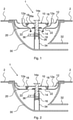
Fig. 1 shows a sectional view of a unit according to a first embodiment, where the sink plug or strainer is in a first upper state. -
Fig. 2 shows a sectional view of a unit shown inFig. 1 , where the sink plug is in a second lower state. -
Fig. 3 shows a perspective view of the sink plug and cylinder shown inFigs. 1 and 2 . -
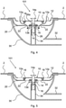
Fig. 4 shows a sectional view of a unit according to a second embodiment, where the sink plug or strainer is in a first upper state. -
Fig. 5 shows a sectional view of unit shown inFig. 4 , where the sink plug is in a second lower state. -
Fig. 6 shows a perspective view of the sink plug and cylinder shown inFigs. 4 and 5 . - In the following, a detailed description of the different embodiments of the invention is disclosed under reference to the accompanying drawings.
- In this description the terms sink plug and strainer will be used interchangeably. However, the scope of protection is defined solely by the appended claims.
- Briefly described, the invention relates to a unit comprising a sink outlet and a sink plug arrangement, the sink plug arrangement constituting the connecting device between the sink outlet and the drain. The purpose of the sink plug arrangement is to provide means for allowing two states, one in which liquid is allowed to pass through the sink outlet and one where liquid is retained within the sink by prohibiting the liquid from passing through the sink outlet.
- In
Figs. 1 to 3 a first embodiment of a unit according to the invention is shown illustrating the sink plug arrangement, generally designated 1. A sink plug orstrainer 10 is a part of thesink plug arrangement 1 and is inFig. 1 shown in an open state where liquid is allowed to pass, via astrainer basket 20, through asink outlet 30, which in turn is attached to a drain (not shown). - The
strainer 10 comprises acircular sieve 12, see alsoFig. 3 , provided with a plurality of circumferentially spaced apartholes 12a, shown with dashed lines inFigs. 1 and 2 . Astem 14 is centrally attached to thesieve 12 and is during operation vertically oriented in thesink outlet 30. The upper end portion of the stem is shaped as aknob 14a adapted to be gripped by a user of the sink plug arrangement. Afirst magnet 16, preferably a permanent magnet, is provided in the stem close to the lower end thereof. Thefirst magnet 16 is vertically oriented with in the described example the negative pole facing upward and the positive pole facing downward. Finally, acircular seal 18 is provided on the lower side of thecircular sieve 12 radially inside of the circumferentially spaced apartholes 12a. - The
basket 20 rests on the rim of a circular hole provided in thesink 2 and is provided with a plurality of spaced apartholes 22 provided radially inside of theholes 12a in thestrainer 10. Thebasket 20 is provided with a central hole adapted to receive a fixedcylinder 26 with a flange 26a at the upper end thereof. The cylinder, which is arranged to receive thestem 14 of thesink plug 10, is at its outer surface provided with threads adapted to cooperate with thesink outlet 30, as will be described hereinafter. - The
sink outlet 30 is substantially bowl-shaped and is provided with anoutlet pipe 32 adapted to connect to drain pipes (not shown). Centrally attached to the bottom of the bowl-shaped outlet is abottom cylinder 34 with inner threads adapted to cooperate with the outer threads of thecylinder 26. The rim of the bowl-shapedoutlet 30 is adapted to rest on the lower surface of thesink 2 which thereby is sandwiched between thebasket 20 and theoutlet 30. By screwing thecylinder 26 into thebottom cylinder 34 thesink 2 is clamped between these two parts, thereby securing the sink plug arrangement into position. Finally, thesink outlet 30 is provided with asecond magnet 36, preferably a permanent magnet, arranged adjacent to thestem 14 of thestrainer 10 during operation of the sink plug arrangement. The term adjacent should in this context be interpreted as being close enough so that the first and second magnets affect each other. In this first embodiment, thesecond magnet 36 is horizontally oriented with one pole, in the described example the negative pole, facing thefirst magnet 16. - The
sink plug arrangement 1 is shown inFig. 1 illustrating a first state where thestrainer 10 is in an upper open state allowing water to leave thesink 2 through thesink plug arrangement 1, as indicated by the arrows. In this state, the polarities of thefirst magnet 16 and thesecond magnet 36 make the magnets attract each other. The attractive force of the magnets keeps thestrainer 10 in the upper position shown inFig.1 . In connection with this it should be appreciated that thestem 14 of thestrainer 10 is vertically movable within the bore of thecylinder 26. - The
sink plug arrangement 1 is further shown inFig. 2 illustrating a second state of the first embodiment where thestrainer 10 is in a lower closed state and thereby prevents water from leaving thesink 2 through thesink plug arrangement 1. When thestrainer 10 is pushed from its upper position downward by a user, for example by exerting a downward force on thegrip 14a, the firstpermanent magnet 16 passes the secondpermanent magnet 36. When the firstpermanent magnet 16 is below the secondpermanent magnet 36, as shown inFig. 2 , the repellant or repulsing force between the magnets forces thestrainer 10 downward to the lower end position shown inFig. 2 . Thestrainer 10 can be returned to its upper open position by a user pulling thegrip 14a upward. - In this second state the polarity of the
permanent magnets strainer 10 in a lower, closed state. This enables thestrainer 10 to create a tight seal with thebasket 20 preventing liquid from leaving thesink 2. This is further enhanced by theseal 18. - In
Fig. 3 thestrainer 10 is shown in perspective together with thecylinder 26 with the secondpermanent magnet 36 attached thereto. The permanent magnet could be part of thecylinder 26 itself, i.e., the cylinder could partly or entirely be formed from a magnetic material. -
Figs. 4-6 illustrate a second embodiment wherein the second magnet, designated 136, preferably a permanent magnet, is located substantially surrounding thecylinder 26 and therewith thestem 14 of thesink plug 10 during operation of thesink plug arrangement 101. The secondpermanent magnet 136 is preferably of a ring type, preferably a ferrite ring type. This means that the second magnet is oriented vertically, with one pole facing upward and the other pole facing downward. In the described example, the positive pole is facing upward and the negative one is facing downward, but the same function is achieved if both the first magnet and the second magnet change orientation. All other parts remain the same as in the first embodiment described above with reference toFigs. 1-3 , although this second embodiment operates in a slightly different way as compared to the first embodiment. -
Fig. 4 shows the second embodiment of a sink plug arrangement, generally designated 101, wherein thestrainer 10 in an upper open position. In this embodiment this maintained by the repellant force between the firstpermanent magnet 16 provided in thestem 14 of thestrainer 10 and the secondpermanent magnet 136 provided as a collar around thecylinder 26 and thereby around thestem 14. In a sense, thestrainer 10 levitates on the magnetic field created by the circularpermanent magnet 136. - When the
strainer 10 is pushed downward by a user, for example by exerting a downward force on thegrip 14a, the firstpermanent magnet 16 passes through the secondpermanent magnet 136. When the firstpermanent magnet 16 is below the secondpermanent magnet 136, as shown inFig. 5 , the repellant force between the magnets forces thestrainer 10 downward to the lower end position shown inFig. 5 . Thestrainer 10 can be returned to its upper open position by a user pulling thegrip 14a upward. - The second embodiment is further appreciated by the perspective view of the
strainer 10 and the second permanent magnet ofFig. 6 . - In both the first embodiment and the second embodiment the
strainer 10 is maintained in its lower closed position by the repellant force between the first permanent magnet provided in thestem 14 of thestrainer 10 and the fixed secondpermanent magnet strainer 10 is maintained by the attractive force between the first and secondpermanent magnets strainer 10 is maintained by the repellant force between the first and secondpermanent magnets sink plug arrangement strainer 10. - Preferred embodiments of a sink plug arrangement have been described. It will be realized that these can be varied without departing from the inventive idea defined by the appended claims.
- Sink plug arrangements with threaded cylinders for the assembly of the arrangement and the guidance of the sink plug or strainer have been shown. It will be appreciated that the inventive idea as defined by the appended claims is applicable to arrangements lacking these parts as long as first and second magnets are provided for maintaining the sink plug in upper and lower positions.
- The described second embodiment is provided with a ring magnet. It will be appreciated that this can be replaced by one or several vertically oriented magnets provided adjacent to the stem of the sink plug. For example, a plurality of spaced apart magnets can be provided oriented vertically surrounding or essentially surrounding the stem of the sink plug during operation thereof.
Claims (14)
- Unit comprising a sink outlet (30) and a Asink plug arrangement (1; 101), the sink plug arrangement (1;101) comprising a sink plug (10) and a first magnet (16) arranged to counteract movement of the sink plug (10) within the sink outlet (30), wherein said sink plug (10) is movable between a first, upper open state and second lower closed state relative the sink outlet (30), and wherein the sink plug (10) is provided with a stem (14) which during operation is vertically oriented in the sink outlet (30), wherein the first magnet (16) is provided in the stem, characterized by a second, fixed magnet (36; 136) arranged to, in the second state, repel the first magnet (16), so that the sink plug (10) is maintained in its lower state by the repellant force between the first and second magnets.
- The unit according to claim 1, the sink plug arrangement (1) comprising a fixed cylinder (26) arranged to receive the stem (14) of the sink plug (10).
- The unit according to claim 2, wherein the second magnet (36; 136) is part of the cylinder (26).
- The unit according to claim 2, wherein the second magnet (36; 136) is located outside the cylinder (26).
- The unit according to any one of claims 1-4, wherein the first magnet (16) is vertically oriented.
- The unit according to any one of claims 1-5, wherein the second magnet (36; 136) is arranged adjacent to the stem (14) of the sink plug (10).
- The unit according to any one of claims 1-6, wherein, in the first state of the sink plug (10), the polarities of the first magnet (16) and the second magnet (36) make the magnets attract each other.
- The unit according to claim 7, wherein the second magnet (36) is horizontally oriented with one pole facing the first magnet.
- The unit according to any one of claims 1-6, wherein, in the first state of the sink plug (10), the polarities of the first magnet (16) and the second magnet (136) make the magnets repel each other.
- The unit according to any one of claims 1-6 and 9, wherein the second magnet (136) is located substantially surrounding the stem (14) of the sink plug (10) .
- The unit according to claim 10, wherein the second magnet (136) is a ring magnet, preferably a ferrite ring magnet.
- The unit according to any one of claims 1-6 and 9-11, wherein the second magnet (136) is oriented vertically, with one pole facing upward and the other pole facing downward.
- The unit according to any one of claims 1-12, wherein the first and second states are substantially opened and closed states relative a longitudinal axis of the sink outlet (30).
- The unit according to any one of claims 1-13, wherein at least one of the first and second magnets (16, 36; 136) is a permanent magnet.
Priority Applications (3)
| Application Number | Priority Date | Filing Date | Title |
|---|---|---|---|
| EP13186006.6A EP2853645B1 (en) | 2013-09-25 | 2013-09-25 | Sink plug arrangement |
| PCT/EP2014/070223 WO2015044127A1 (en) | 2013-09-25 | 2014-09-23 | Sink plug arrangement |
| US15/077,958 US10538903B2 (en) | 2013-09-25 | 2016-03-23 | Sink plug arrangement |
Applications Claiming Priority (1)
| Application Number | Priority Date | Filing Date | Title |
|---|---|---|---|
| EP13186006.6A EP2853645B1 (en) | 2013-09-25 | 2013-09-25 | Sink plug arrangement |
Publications (2)
| Publication Number | Publication Date |
|---|---|
| EP2853645A1 EP2853645A1 (en) | 2015-04-01 |
| EP2853645B1 true EP2853645B1 (en) | 2022-03-09 |
Family
ID=49274430
Family Applications (1)
| Application Number | Title | Priority Date | Filing Date |
|---|---|---|---|
| EP13186006.6A Active EP2853645B1 (en) | 2013-09-25 | 2013-09-25 | Sink plug arrangement |
Country Status (3)
| Country | Link |
|---|---|
| US (1) | US10538903B2 (en) |
| EP (1) | EP2853645B1 (en) |
| WO (1) | WO2015044127A1 (en) |
Families Citing this family (7)
| Publication number | Priority date | Publication date | Assignee | Title |
|---|---|---|---|---|
| US9797121B2 (en) * | 2015-02-13 | 2017-10-24 | Joe Francis | Systems and methods for unclogging a drain |
| US10030373B1 (en) * | 2015-03-27 | 2018-07-24 | Carlos M. Batista | Apparatus and method to reduce magnetic debris entrained in waste water |
| SE541224C2 (en) * | 2016-06-20 | 2019-05-07 | Prevex Ab Oy | Sink plug arrangement |
| US10619340B2 (en) * | 2016-07-17 | 2020-04-14 | Michael Joab Cotter | Internal trap drain with adjustable height strainer and high mass seal |
| RU176477U1 (en) * | 2017-05-04 | 2018-01-22 | Владимир Николаевич Смолин | DRAIN MANAGEMENT UNIT |
| US11549246B1 (en) * | 2019-12-27 | 2023-01-10 | Vasile Mociran | Magnetically actuated pop-up drain assembly |
| CN113356313B (en) * | 2021-05-21 | 2022-08-30 | 福建省天力卫浴科技有限公司 | Plastic bouncing core |
Family Cites Families (16)
| Publication number | Priority date | Publication date | Assignee | Title |
|---|---|---|---|---|
| US2736040A (en) | 1956-02-28 | Crumcup strainer and stopper | ||
| US2454333A (en) * | 1945-11-05 | 1948-11-23 | James M Moon | Electric drain stopper |
| US2708893A (en) * | 1951-12-18 | 1955-05-24 | American Can Co | Multiple part spline for closing side seams of can bodies |
| GB776320A (en) | 1954-06-03 | 1957-06-05 | Gen Electric | Improvements in and relating to drain valves for sinks or the like |
| US3652054A (en) * | 1970-06-19 | 1972-03-28 | Interlab Inc | Magnetic drain valves |
| DE2708893C3 (en) * | 1977-03-02 | 1979-08-30 | Hermann Dipl.-Ing. Dr.Oec. 4300 Essen Tiefenbach | Drain plug |
| US4692948A (en) | 1986-12-22 | 1987-09-15 | Jomar International, Ltd. | Sink strainer having a magnet |
| US5208921A (en) * | 1992-01-13 | 1993-05-11 | Nicoll James D | Magnetic drain stopper |
| US5640724A (en) * | 1995-04-24 | 1997-06-24 | Holmes; John W. | Magnetically activated lavatory drain plug |
| US6282730B1 (en) * | 1998-04-15 | 2001-09-04 | E-Ticket Enterprises, Llc | Magnetic stopper |
| US7517452B2 (en) | 2003-12-10 | 2009-04-14 | Speciality Plumbling Supplies Pty Ltd | Filter assembly |
| ITMI20071776A1 (en) | 2007-09-14 | 2009-03-15 | Trane Bvba | SET OF CLOSURE OF THE DISCHARGE OF SANITARY AND SANITARY EMPLOYING THE SAME |
| CA2659992A1 (en) * | 2008-04-10 | 2009-10-10 | Scott Duncan | Magnetically actuated drain stopper apparatus |
| CN101614035B (en) | 2008-06-25 | 2010-12-08 | 王兆保 | Magnetic launching plug piece |
| NL1036023C (en) * | 2008-10-07 | 2010-04-08 | I-Drains Prod Bv | VALVE. |
| US9427114B2 (en) * | 2011-06-16 | 2016-08-30 | Henry Tong | Magnetic drain stopper assembly and method |
-
2013
- 2013-09-25 EP EP13186006.6A patent/EP2853645B1/en active Active
-
2014
- 2014-09-23 WO PCT/EP2014/070223 patent/WO2015044127A1/en active Application Filing
-
2016
- 2016-03-23 US US15/077,958 patent/US10538903B2/en active Active
Also Published As
| Publication number | Publication date |
|---|---|
| US10538903B2 (en) | 2020-01-21 |
| WO2015044127A1 (en) | 2015-04-02 |
| EP2853645A1 (en) | 2015-04-01 |
| US20160201307A1 (en) | 2016-07-14 |
Similar Documents
| Publication | Publication Date | Title |
|---|---|---|
| EP2853645B1 (en) | Sink plug arrangement | |
| JP5054620B2 (en) | Ventilation valve | |
| MX2020007601A (en) | A capsule, a system for preparing a potable beverage from such a capsule and use of such a capsule in a beverage preparation device. | |
| CN204344395U (en) | There is the electromagnetic pump of the valve constitution of improvement | |
| CA2965922A1 (en) | Push-type drain stopper for pop-up drain | |
| JP6317187B2 (en) | Ventilation valve and piping structure | |
| WO2020024874A1 (en) | Novel structure of magnetic suspension floor drain core | |
| RU2017100258A (en) | CLOSING DEVICE FOR BEVERAGE CONTAINER | |
| JP2010216210A (en) | Drain plug | |
| US8857471B2 (en) | Control structure of wall-mounted faucet | |
| US20140000022A1 (en) | Thread-in drain for lavatories. | |
| NL1036023C (en) | VALVE. | |
| US20220042292A1 (en) | Bathtub Drain Stopper | |
| CN203363233U (en) | Electromagnetic draining valve | |
| RU2020114712A (en) | SEALING DEVICE AND METHODS OF ITS USE WITH FLUID VALVES | |
| EP2967261B1 (en) | A bath or basin waste | |
| US9783969B2 (en) | Bathroom fittings | |
| EP3472395B1 (en) | Sink plug arrangement | |
| JP2006217858A (en) | Baiting tool for attracting fish | |
| US20110175001A1 (en) | Gravity driven valve switch | |
| US20110265879A1 (en) | Secondary bleed valve for dual flush valve | |
| GB2514578A (en) | Lipstick case | |
| US20170037981A1 (en) | Self-shut valve for faucet | |
| JP5936912B2 (en) | Stopper device | |
| US20170268212A1 (en) | Threaded easy Install and removal pop-up drain stopper |
Legal Events
| Date | Code | Title | Description |
|---|---|---|---|
| PUAI | Public reference made under article 153(3) epc to a published international application that has entered the european phase |
Free format text: ORIGINAL CODE: 0009012 |
|
| 17P | Request for examination filed |
Effective date: 20130925 |
|
| AK | Designated contracting states |
Kind code of ref document: A1 Designated state(s): AL AT BE BG CH CY CZ DE DK EE ES FI FR GB GR HR HU IE IS IT LI LT LU LV MC MK MT NL NO PL PT RO RS SE SI SK SM TR |
|
| AX | Request for extension of the european patent |
Extension state: BA ME |
|
| R17P | Request for examination filed (corrected) |
Effective date: 20151001 |
|
| RBV | Designated contracting states (corrected) |
Designated state(s): AL AT BE BG CH CY CZ DE DK EE ES FI FR GB GR HR HU IE IS IT LI LT LU LV MC MK MT NL NO PL PT RO RS SE SI SK SM TR |
|
| STAA | Information on the status of an ep patent application or granted ep patent |
Free format text: STATUS: EXAMINATION IS IN PROGRESS |
|
| 17Q | First examination report despatched |
Effective date: 20190712 |
|
| STAA | Information on the status of an ep patent application or granted ep patent |
Free format text: STATUS: EXAMINATION IS IN PROGRESS |
|
| GRAP | Despatch of communication of intention to grant a patent |
Free format text: ORIGINAL CODE: EPIDOSNIGR1 |
|
| STAA | Information on the status of an ep patent application or granted ep patent |
Free format text: STATUS: GRANT OF PATENT IS INTENDED |
|
| INTG | Intention to grant announced |
Effective date: 20211019 |
|
| GRAS | Grant fee paid |
Free format text: ORIGINAL CODE: EPIDOSNIGR3 |
|
| GRAA | (expected) grant |
Free format text: ORIGINAL CODE: 0009210 |
|
| STAA | Information on the status of an ep patent application or granted ep patent |
Free format text: STATUS: THE PATENT HAS BEEN GRANTED |
|
| AK | Designated contracting states |
Kind code of ref document: B1 Designated state(s): AL AT BE BG CH CY CZ DE DK EE ES FI FR GB GR HR HU IE IS IT LI LT LU LV MC MK MT NL NO PL PT RO RS SE SI SK SM TR |
|
| REG | Reference to a national code |
Ref country code: GB Ref legal event code: FG4D |
|
| REG | Reference to a national code |
Ref country code: CH Ref legal event code: EP Ref country code: AT Ref legal event code: REF Ref document number: 1474271 Country of ref document: AT Kind code of ref document: T Effective date: 20220315 |
|
| REG | Reference to a national code |
Ref country code: DE Ref legal event code: R096 Ref document number: 602013081064 Country of ref document: DE |
|
| REG | Reference to a national code |
Ref country code: IE Ref legal event code: FG4D |
|
| REG | Reference to a national code |
Ref country code: SE Ref legal event code: TRGR |
|
| REG | Reference to a national code |
Ref country code: LT Ref legal event code: MG9D |
|
| REG | Reference to a national code |
Ref country code: NL Ref legal event code: MP Effective date: 20220309 |
|
| PG25 | Lapsed in a contracting state [announced via postgrant information from national office to epo] |
Ref country code: RS Free format text: LAPSE BECAUSE OF FAILURE TO SUBMIT A TRANSLATION OF THE DESCRIPTION OR TO PAY THE FEE WITHIN THE PRESCRIBED TIME-LIMIT Effective date: 20220309 Ref country code: NO Free format text: LAPSE BECAUSE OF FAILURE TO SUBMIT A TRANSLATION OF THE DESCRIPTION OR TO PAY THE FEE WITHIN THE PRESCRIBED TIME-LIMIT Effective date: 20220609 Ref country code: LT Free format text: LAPSE BECAUSE OF FAILURE TO SUBMIT A TRANSLATION OF THE DESCRIPTION OR TO PAY THE FEE WITHIN THE PRESCRIBED TIME-LIMIT Effective date: 20220309 Ref country code: HR Free format text: LAPSE BECAUSE OF FAILURE TO SUBMIT A TRANSLATION OF THE DESCRIPTION OR TO PAY THE FEE WITHIN THE PRESCRIBED TIME-LIMIT Effective date: 20220309 Ref country code: BG Free format text: LAPSE BECAUSE OF FAILURE TO SUBMIT A TRANSLATION OF THE DESCRIPTION OR TO PAY THE FEE WITHIN THE PRESCRIBED TIME-LIMIT Effective date: 20220609 |
|
| REG | Reference to a national code |
Ref country code: AT Ref legal event code: MK05 Ref document number: 1474271 Country of ref document: AT Kind code of ref document: T Effective date: 20220309 |
|
| PG25 | Lapsed in a contracting state [announced via postgrant information from national office to epo] |
Ref country code: LV Free format text: LAPSE BECAUSE OF FAILURE TO SUBMIT A TRANSLATION OF THE DESCRIPTION OR TO PAY THE FEE WITHIN THE PRESCRIBED TIME-LIMIT Effective date: 20220309 Ref country code: GR Free format text: LAPSE BECAUSE OF FAILURE TO SUBMIT A TRANSLATION OF THE DESCRIPTION OR TO PAY THE FEE WITHIN THE PRESCRIBED TIME-LIMIT Effective date: 20220610 Ref country code: FI Free format text: LAPSE BECAUSE OF FAILURE TO SUBMIT A TRANSLATION OF THE DESCRIPTION OR TO PAY THE FEE WITHIN THE PRESCRIBED TIME-LIMIT Effective date: 20220309 |
|
| PG25 | Lapsed in a contracting state [announced via postgrant information from national office to epo] |
Ref country code: NL Free format text: LAPSE BECAUSE OF FAILURE TO SUBMIT A TRANSLATION OF THE DESCRIPTION OR TO PAY THE FEE WITHIN THE PRESCRIBED TIME-LIMIT Effective date: 20220309 |
|
| PG25 | Lapsed in a contracting state [announced via postgrant information from national office to epo] |
Ref country code: SM Free format text: LAPSE BECAUSE OF FAILURE TO SUBMIT A TRANSLATION OF THE DESCRIPTION OR TO PAY THE FEE WITHIN THE PRESCRIBED TIME-LIMIT Effective date: 20220309 Ref country code: SK Free format text: LAPSE BECAUSE OF FAILURE TO SUBMIT A TRANSLATION OF THE DESCRIPTION OR TO PAY THE FEE WITHIN THE PRESCRIBED TIME-LIMIT Effective date: 20220309 Ref country code: RO Free format text: LAPSE BECAUSE OF FAILURE TO SUBMIT A TRANSLATION OF THE DESCRIPTION OR TO PAY THE FEE WITHIN THE PRESCRIBED TIME-LIMIT Effective date: 20220309 Ref country code: PT Free format text: LAPSE BECAUSE OF FAILURE TO SUBMIT A TRANSLATION OF THE DESCRIPTION OR TO PAY THE FEE WITHIN THE PRESCRIBED TIME-LIMIT Effective date: 20220711 Ref country code: ES Free format text: LAPSE BECAUSE OF FAILURE TO SUBMIT A TRANSLATION OF THE DESCRIPTION OR TO PAY THE FEE WITHIN THE PRESCRIBED TIME-LIMIT Effective date: 20220309 Ref country code: EE Free format text: LAPSE BECAUSE OF FAILURE TO SUBMIT A TRANSLATION OF THE DESCRIPTION OR TO PAY THE FEE WITHIN THE PRESCRIBED TIME-LIMIT Effective date: 20220309 Ref country code: CZ Free format text: LAPSE BECAUSE OF FAILURE TO SUBMIT A TRANSLATION OF THE DESCRIPTION OR TO PAY THE FEE WITHIN THE PRESCRIBED TIME-LIMIT Effective date: 20220309 Ref country code: AT Free format text: LAPSE BECAUSE OF FAILURE TO SUBMIT A TRANSLATION OF THE DESCRIPTION OR TO PAY THE FEE WITHIN THE PRESCRIBED TIME-LIMIT Effective date: 20220309 |
|
| PG25 | Lapsed in a contracting state [announced via postgrant information from national office to epo] |
Ref country code: PL Free format text: LAPSE BECAUSE OF FAILURE TO SUBMIT A TRANSLATION OF THE DESCRIPTION OR TO PAY THE FEE WITHIN THE PRESCRIBED TIME-LIMIT Effective date: 20220309 Ref country code: IS Free format text: LAPSE BECAUSE OF FAILURE TO SUBMIT A TRANSLATION OF THE DESCRIPTION OR TO PAY THE FEE WITHIN THE PRESCRIBED TIME-LIMIT Effective date: 20220709 Ref country code: AL Free format text: LAPSE BECAUSE OF FAILURE TO SUBMIT A TRANSLATION OF THE DESCRIPTION OR TO PAY THE FEE WITHIN THE PRESCRIBED TIME-LIMIT Effective date: 20220309 |
|
| REG | Reference to a national code |
Ref country code: DE Ref legal event code: R097 Ref document number: 602013081064 Country of ref document: DE |
|
| PLBE | No opposition filed within time limit |
Free format text: ORIGINAL CODE: 0009261 |
|
| STAA | Information on the status of an ep patent application or granted ep patent |
Free format text: STATUS: NO OPPOSITION FILED WITHIN TIME LIMIT |
|
| PG25 | Lapsed in a contracting state [announced via postgrant information from national office to epo] |
Ref country code: DK Free format text: LAPSE BECAUSE OF FAILURE TO SUBMIT A TRANSLATION OF THE DESCRIPTION OR TO PAY THE FEE WITHIN THE PRESCRIBED TIME-LIMIT Effective date: 20220309 |
|
| 26N | No opposition filed |
Effective date: 20221212 |
|
| PG25 | Lapsed in a contracting state [announced via postgrant information from national office to epo] |
Ref country code: SI Free format text: LAPSE BECAUSE OF FAILURE TO SUBMIT A TRANSLATION OF THE DESCRIPTION OR TO PAY THE FEE WITHIN THE PRESCRIBED TIME-LIMIT Effective date: 20220309 |
|
| REG | Reference to a national code |
Ref country code: DE Ref legal event code: R119 Ref document number: 602013081064 Country of ref document: DE |
|
| PG25 | Lapsed in a contracting state [announced via postgrant information from national office to epo] |
Ref country code: MC Free format text: LAPSE BECAUSE OF FAILURE TO SUBMIT A TRANSLATION OF THE DESCRIPTION OR TO PAY THE FEE WITHIN THE PRESCRIBED TIME-LIMIT Effective date: 20220309 |
|
| REG | Reference to a national code |
Ref country code: CH Ref legal event code: PL |
|
| GBPC | Gb: european patent ceased through non-payment of renewal fee |
Effective date: 20220925 |
|
| REG | Reference to a national code |
Ref country code: BE Ref legal event code: MM Effective date: 20220930 |
|
| PG25 | Lapsed in a contracting state [announced via postgrant information from national office to epo] |
Ref country code: LU Free format text: LAPSE BECAUSE OF NON-PAYMENT OF DUE FEES Effective date: 20220925 |
|
| PG25 | Lapsed in a contracting state [announced via postgrant information from national office to epo] |
Ref country code: LI Free format text: LAPSE BECAUSE OF NON-PAYMENT OF DUE FEES Effective date: 20220930 Ref country code: IT Free format text: LAPSE BECAUSE OF FAILURE TO SUBMIT A TRANSLATION OF THE DESCRIPTION OR TO PAY THE FEE WITHIN THE PRESCRIBED TIME-LIMIT Effective date: 20220309 Ref country code: IE Free format text: LAPSE BECAUSE OF NON-PAYMENT OF DUE FEES Effective date: 20220925 Ref country code: FR Free format text: LAPSE BECAUSE OF NON-PAYMENT OF DUE FEES Effective date: 20220930 Ref country code: DE Free format text: LAPSE BECAUSE OF NON-PAYMENT OF DUE FEES Effective date: 20230401 Ref country code: CH Free format text: LAPSE BECAUSE OF NON-PAYMENT OF DUE FEES Effective date: 20220930 |
|
| PG25 | Lapsed in a contracting state [announced via postgrant information from national office to epo] |
Ref country code: BE Free format text: LAPSE BECAUSE OF NON-PAYMENT OF DUE FEES Effective date: 20220930 |
|
| PG25 | Lapsed in a contracting state [announced via postgrant information from national office to epo] |
Ref country code: GB Free format text: LAPSE BECAUSE OF NON-PAYMENT OF DUE FEES Effective date: 20220925 |
|
| PGFP | Annual fee paid to national office [announced via postgrant information from national office to epo] |
Ref country code: SE Payment date: 20230919 Year of fee payment: 11 |
|
| PG25 | Lapsed in a contracting state [announced via postgrant information from national office to epo] |
Ref country code: HU Free format text: LAPSE BECAUSE OF FAILURE TO SUBMIT A TRANSLATION OF THE DESCRIPTION OR TO PAY THE FEE WITHIN THE PRESCRIBED TIME-LIMIT; INVALID AB INITIO Effective date: 20130925 |