EP2853489B1 - Doppeldrucksteuerung für einen Rotorbremsenaktuator für senkrechtstartendes Flugzeug - Google Patents
Doppeldrucksteuerung für einen Rotorbremsenaktuator für senkrechtstartendes Flugzeug Download PDFInfo
- Publication number
- EP2853489B1 EP2853489B1 EP13194422.5A EP13194422A EP2853489B1 EP 2853489 B1 EP2853489 B1 EP 2853489B1 EP 13194422 A EP13194422 A EP 13194422A EP 2853489 B1 EP2853489 B1 EP 2853489B1
- Authority
- EP
- European Patent Office
- Prior art keywords
- rotor
- master cylinder
- brake actuator
- hydraulic fluid
- pressure
- Prior art date
- Legal status (The legal status is an assumption and is not a legal conclusion. Google has not performed a legal analysis and makes no representation as to the accuracy of the status listed.)
- Active
Links
Images

Classifications
-
- B—PERFORMING OPERATIONS; TRANSPORTING
- B64—AIRCRAFT; AVIATION; COSMONAUTICS
- B64C—AEROPLANES; HELICOPTERS
- B64C27/00—Rotorcraft; Rotors peculiar thereto
- B64C27/04—Helicopters
- B64C27/12—Rotor drives
-
- B—PERFORMING OPERATIONS; TRANSPORTING
- B60—VEHICLES IN GENERAL
- B60T—VEHICLE BRAKE CONTROL SYSTEMS OR PARTS THEREOF; BRAKE CONTROL SYSTEMS OR PARTS THEREOF, IN GENERAL; ARRANGEMENT OF BRAKING ELEMENTS ON VEHICLES IN GENERAL; PORTABLE DEVICES FOR PREVENTING UNWANTED MOVEMENT OF VEHICLES; VEHICLE MODIFICATIONS TO FACILITATE COOLING OF BRAKES
- B60T15/00—Construction arrangement, or operation of valves incorporated in power brake systems and not covered by groups B60T11/00 or B60T13/00
- B60T15/02—Application and release valves
Definitions
- the following description relates to control of a rotor brake actuator system for vertical lift aircraft.
- the rotor brake of a vertical lift aircraft such as a helicopter can be applied with hydraulic actuators that use multiple hydraulic pressure settings for different operational situations.
- a first pressure setting is a higher pressure than a second pressure setting.
- a lower pressure e.g. 220 psi
- a higher pressure e.g. 800 psi
- US5462137 discloses a braking system comprising a disk brake including a hydraulic actuator which has force amplification and a mechanical transmission connecting a control member to the actuator.
- the amplification is obtained by the section difference between a control piston and a free piston of the actuator, exerting a braking force.
- a rotor blade rotation control master cylinder assembly for vertical lift aircraft includes a master cylinder, a rotor brake actuator, a low pressure relief valve, a high pressure relief valve, and an isolation valve.
- the master cylinder is configured to be activated by movement of a rotor blade rotation control handle of a vertical lift aircraft to move pressurized hydraulic fluid through one or more conduits.
- the rotor brake actuator is connected to the master cylinder and configured to engage a rotor brake of the vertical lift aircraft in response to receiving hydraulic fluid at a hydraulic fluid pressure from the master cylinder.
- the low pressure relief valve fluidly is connected in parallel to the master cylinder and the rotor brake actuator and configured to transmit pressurized hydraulic fluid away from the rotor brake actuator in response to the hydraulic fluid pressure exceeding a first pressure threshold of the low pressure relief valve.
- the high pressure relief valve is connected in parallel to the master cylinder, the rotor brake actuator and the low pressure relief valve and configured to transmit pressurized hydraulic fluid away from the rotor brake actuator in response to the hydraulic fluid pressure exceeding a second pressure threshold of the high pressure relief valve.
- the second pressure threshold is higher than the first pressure threshold, and the low pressure relief valve can be isolated from the high pressure relief valve.
- the isolation valve is connected in series to the master cylinder and the low pressure relief valve.
- the master cylinder is configured to push the hydraulic fluid at a first pressure to the rotor brake actuator in response to the isolation valve being open and to push the hydraulic fluid at a second pressure that is lower than the first pressure in response to the isolation valve being closed.
- the rotor brake of a vertical lift aircraft such as a helicopter can be applied with hydraulic actuators that use multiple hydraulic pressure settings for different operational situations.
- a first pressure can be applied to the rotor brake to slowly stop the rotor, such as an engine shutdown after landing.
- a second pressure can be applied to the rotor brake to hold the rotor from rotation, e.g., during engine start-up.
- the first pressure used to slowly stop the rotor can be lower than the second pressure to hold the rotor from rotation.
- the first pressure setting can be provided by a manual cylinder
- the second pressure setting can be provided by an additional separate motor-driven pump.
- the aircraft hydraulic system pressure is used to provide pressure to the rotor brake to slow, stop, or hold the rotor. Any additional components coupled to the aircraft hydraulic system can be sources of failure and stress on the system. In some typical implementations, a pressure setting is achieved with multiple strokes of a handle by a crewmember.
- the example rotor blade rotation control assembly (the "rotor brake control circuit assembly") herein can provide multiple pressure settings to a rotor brake without the use of aircraft hydraulic system pressure or an additional separate motor-driven pump.
- the example rotor brake control circuit assembly also can provide adequate pressure from a single stroke of the rotor blade rotation control handle (the "rotor brake handle").
- the example rotor brake control circuit assembly described herein can provide multiple pressure settings at a reduced weight and cost over other assemblies.
- the example rotor brake control circuit assembly can provide multiple pressure settings using only a single master cylinder.
- the example rotor brake control circuit assembly can allow the pilot to precisely control the position of the rotor blade, e.g., to position the rotor blade and stop it at a specific position.
- the rotor brake can be maintained for several hours with little to no loss in pressure.
- the rotor brake can act as a parking brake for overnight storage. This allows operators to not have to secure the blades manually when parking for short periods of time.
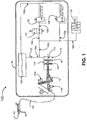
- FIG. 1 is a schematic of an example rotor brake actuator control circuit system 100.
- the example rotor brake actuator control circuit system 100 includes a handle 102, a linkage 104, a master cylinder assembly 110, and plumbing conduit tube 130f.
- the handle 102 is connected to the linkage 104, which is connected to the master cylinder assembly 110 via input lever 112.
- the input lever 112 is coupled to stops 114a, 114b and a piston 116.
- the piston 116 resides inside a master cylinder 118 and forms a main chamber 119 within the master cylinder 118.
- the master cylinder assembly 110 also includes a reservoir 120 fluidly connected to the master cylinder 118 through a check valve 122.
- the master cylinder assembly 110 includes an isolation valve 124, a low pressure relief valve 126, and a high pressure relief valve 128.
- the rotor brake actuator control circuit system 100 also includes conduits 130a, 130b, 130c, 130d, 130e, 130g and a rotor brake actuator 132.
- the master cylinder 118, the reservoir 120, the check valve 122, the isolation valve 124, the low pressure relief valve 126, the high pressure relief valve 128, and the rotor brake actuator 132 are all fluidly connected via conduits 130a, 130b, 130c, 130d, 130e, 130f, 130g.
- the low pressure relief valve 126, the high pressure relief valve 128, and the rotor brake actuator 132 are fluidly connected in parallel to master cylinder 118 and conduits 130a and 130b via conduits 130c and 130d, 130e, and 130f, respectively.
- the conduits 130a, 130b, 130c, 130d, 130e, 130f, and 130g are ports between components.
- the conduits 130a, 130b, 130c, 130d, 130e, 130f, and 130g can include tubing or piping, or the conduits can be coupled through other components.
- the rotor brake actuator system 100 can include additional or different features, and the components can be configured as shown in FIG. 1 , or they may be configured in another manner.
- the components of the master cylinder assembly 110 can be incorporated into a single unit or separated into multiple units.
- the handle 102 can be a lever that can be positioned between two extreme positions, "ON” and "OFF.” During operation, the handle 102 can be positioned at either extreme position or at any position in between. In some implementations, the handle 102 is a manually-operated lever that can be pivoted at one end.
- the handle 102 can be composed of two or more components that together provide the mechanical action.
- the handle 102 can be configured to operate with a load spread over the actuation distance between ON and OFF.
- the handle 102 is coupled to a linkage 104.
- the linkage 104 can be a mechanical linkage that is configured to transfer the translation of handle 102 into the master cylinder assembly 110.
- the linkage 104 can include multiple links, bellcranks, cables, hydraulic systems or other components.
- the linkage 104 can include a cable coupling the handle 102 to the input lever 112. In this case, translating the handle 102 will translate the input lever 112 through the linkage 104.
- Input lever 112 is a mechanism coupled to linkage 104 and piston 116.
- the piston 116 resides within master cylinder 118.
- the input lever 112 can include one or more levers, linkages, or components. Operation of handle 102 can actuate input lever 112 via linkage 104.
- the actuation of input lever 112 can be proportional to the distance the handle 102 is operated.
- Input lever 112 is coupled to piston 116 such that piston 116 is translated within cylinder 118 when input lever 112 is actuated.
- the travel distance of input lever 112 is limited by stops 114a, 114b.
- the stops 114a, 114b are rigid and fixed members that prevent the input lever 112 from traveling beyond extreme positions corresponding to ON and OFF.
- the stops 114a and 114b are positioned at positions that correspond to the ON and OFF positions of the handle 102.
- the main chamber 119 of the master cylinder 118 is fluidly connected to reservoir 120 via conduit 130a.
- Reservoir 120 can contain a fluid such as a hydraulic fluid.
- Check valve 122 is located in the conduit 130a between the main chamber 119 and the reservoir 120. Check valve 122 allows fluid to flow from the reservoir 120 into the main chamber 119 through conduit 130a but prevents fluid from flowing in reverse from the main chamber 119 into the reservoir 120 through the same conduit 130a.
- Fluid can be flowed from the reservoir 120 into the master cylinder 118 during the stroke of the piston 116.
- the piston 116 retracts and pulls fluid from the reservoir 120 into the main chamber 119.
- the piston 116 extends and ports fluid under pressure from the main chamber 119 into the conduit 130a.
- the conduit 130a is fluidly connected to conduits 130b, 130c, 130d, 130e, and 130f.
- Low pressure relief valve 126 is connected to conduits 130c and 130d
- high pressure relief valve 128 is connected to conduit 130e. If the fluid pressure in the conduits 130c and 130d exceeds some first specified value with the isolation valve 124 open, the low pressure relief valve 126 will open and excess fluid will be ported to reservoir 120 via conduit 130g until the fluid pressure falls below the specified value. If the fluid pressure in the conduit 130e exceeds some second specified value with the isolation valve 124 closed, the high pressure relief valve 128 will open and excess fluid will be ported to reservoir 120 via conduit 130g until the fluid pressure falls below the specified value. In this example, the first specified pressure value associated with the low pressure relief valve 126 is lower than the second specified pressure value associated with the high pressure relief valve 128.
- Rotor brake actuator 132 is connected to conduit 130d.
- the rotor brake actuator 132 can impart a braking force onto the rotor of a vertical lift aircraft (not shown).
- the braking force could be provided by a mechanism such as calipers that are actuated by the rotor brake actuator 132.
- the fluid in conduits 130a and 130b is also ported under pressure into conduit 130c during extension of the piston 116.
- the isolation valve 124 is a two-position valve that operates to open and close the conduit 130d.
- the isolation valve 124 can include one or more solenoids or other mechanical components.
- the isolation valve 124 can be engaged or disengaged after receiving a mechanical or electronic signal.
- the isolation valve 124 can be controlled by the aircraft's avionics system or a pilot-operated switch. For example, isolation valve 124 can be engaged after receiving an electronic signal from the aircraft's avionics system. If the isolation valve 124 is open, the fluid can be ported via conduit 130c through isolation valve 124 and into low pressure relief valve 126 via conduit 130d. When the isolation valve 124 is closed, then the low pressure relief valve 126 is no longer fluidly connected to conduit 130b.
- isolation valve 124 When isolation valve 124 is closed, the pressure of the fluid in the conduits 130a, 130b, 130c, 130e, and 130f is controlled (e.g., limited) by the high pressure relief valve 128, and the maximum braking force imparted by the rotor brake actuator 132 is controlled by the high pressure relief valve 128.
- isolation valve 124 When isolation valve 124 is open, the pressure of the fluid in the conduits 130a, 130b, 130c, 130d, 130e, and 130f is controlled by both the low pressure relief valve 126 and the high pressure relief valve 128. Since the low pressure relief valve 126 has a lower pressure threshold value than the high pressure relief valve 128, then the maximum braking force imparted by the rotor brake actuator 132 is controlled by the pressure threshold value of the low pressure relief valve 126. Thus, if the isolation valve 124 is open, the maximum braking force imparted by the rotor brake actuator 132 is lower than the maximum force imparted when the isolation valve 124 is closed.
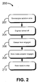
- FIG. 2 is a flow chart diagram of example rotor braking process 200.
- the example rotor braking process 200 is a process to slow or stop the rotors of a vertical lift aircraft.
- the example rotor braking process 200 can be based on (e.g., implemented by) the example rotor brake actuator control circuit system 100 described in FIG. 1 .
- the rotor braking process 200 corresponds to the configuration in FIG. 1 in which the isolation valve is open.
- an interlock prevents the rotor brake system from being operated when the engines are on.
- the interlock system can be controlled by the aircraft's avionics system, and include sensors or signals coupled to aircraft components.
- the isolation valve is de-energized.
- the isolation valve can be a valve such as isolation valve 124 in FIG. 1 .
- the isolation valve can be de-energized manually by the pilot.
- the isolation valve can also be de-energized automatically, such as in response to a signal from the aircraft's avionics system.
- the engines of the vertical lift aircraft are turned off.
- the engines can be turned off after the aircraft has landed. Without engine power, the rotors begin to slow.
- the manual lever can be engaged.
- the manual lever can be a handle or mechanism such as handle 102 shown in FIG. 1 .
- the manual lever can be translated from an OFF position to an ON position or any position in between. At the OFF position, no braking force is applied to the rotor. At ON position, the maximum braking force is applied to the rotor.
- An intermediate position between OFF and ON can provide an intermediate amount of braking force that can be proportional to that intermediate position.
- the manual lever can be configured to produce maximum rotor braking after a single translation from OFF to ON.
- the manual lever can be configured to distribute manual pilot input work required throughout the full travel of the handle to activate the master cylinder to minimize the maximum handle load at all handle positions. This can keep pilot load to a minimal, manageable level. This can also allow a design to be utilized that does not require pressure from the aircraft hydraulic system or require an electric motor driven pump.
- the operation of the manual lever causes the rotor brake actuator to engage, exerting a braking force on the rotor.
- the rotor brake can include calipers coupled to the tail rotor drive shaft or other parts within the drive system.
- the rotor brake actuator can be controlled indirectly via the rotor brake control circuit assembly by the movement of the manual lever.
- the braking force slows the rotor to a stop.
- the handle can be moved towards ON or OFF to allow the master cylinder to increase or decrease rotor brake pressure. This can allow the pilot to position the rotor blade and stop it at a specific position.
- the rotor brake actuator pressure can be maintained for several hours with little to no loss in pressure. For example, the rotor brake can act as a parking brake for overnight storage.
- FIG. 3 is a flow chart diagram of example rotor braking process 300.
- the example rotor braking process 300 is a process to hold the rotors of a vertical lift aircraft upon initial engine start-up.
- the example rotor braking process 300 can be based on the example rotor brake actuator control circuit system 100 described in FIG. 1 .
- the example rotor braking process 300 corresponds to a vertical lift aircraft which has its engines and systems initially turned off, and the rotor brake disengaged. In some implementations, the rotor brake is still engaged from a previous parking configuration. The pilot begins the engine startup procedure by turning on the power.
- the isolation valve is energized either manually via an electrical switch or automatically via the avionics system. When the isolation valve is energized, it closes and thus isolates the low-pressure relief valve from the rotor brake control circuit assembly.
- the pilot sets the rotor brake.
- the handle 102 is set to the fully ON position.
- the low-pressure relief valve is isolated from the rotor brake control circuit assembly by the isolation valve, so the pressure in the rotor brake control circuit assembly is limited by the high pressure relief valve.
- the rotor brake is applied at a relatively high pressure.
- the pilot starts the first engine of the aircraft.
- the rotors are held from turning by the rotor brake (at 308).
- the pilot disengages the rotor brake by setting the handle to the fully OFF position. Once the brake is disengaged, the rotors are able to turn under the power of the first engine. After the rotors are free to turn, the pilot also can activate a second aircraft engine (at 312).
- the isolation valve is disengaged, either manually via an electrical switch or automatically via the avionics system.
Landscapes
- Engineering & Computer Science (AREA)
- Mechanical Engineering (AREA)
- Aviation & Aerospace Engineering (AREA)
- Transportation (AREA)
- Regulating Braking Force (AREA)
- Valves And Accessory Devices For Braking Systems (AREA)
Claims (11)
- Eine Rotorblatt-Rotationssteuerungs-Hauptzylinderanordnung (110) für ein senkrechtstartendes Flugzeug, die Folgendes aufweist:einen Hauptzylinder (118), der so gestaltet ist, dass er durch einen Druck eines Rotorblatt-Rotationssteuerungs-Hebels (102) eines senkrechtstartenden Flugzeugs aktiviert wird, um druckbeaufschlagte Hydraulikflüssigkeit durch eine oder mehrere Leitungen (130) zu leiten, und der so gestaltet ist, dass er die druckbeaufschlagte Flüssigkeit in einen Rotorbremsenaktuator (132) leitet;dadurch gekennzeichnet, dass die Anordnung darüberhinaus Folgendes aufweist:ein Niederdruckbegrenzungsventil (126), das fließbar mit dem Hauptzylinder (118) verbunden und so gestaltet ist, dass es, als Reaktion darauf, dass der Hydraulikflüssigkeitsdruck eine erste Druckschwelle des Niederdruckbegrenzungsventils (126) überschreitet, Hydraulikflüssigkeit weiterleitet;ein Hochdruckbegrenzungsventil (128), das parallel mit dem Hauptzylinder (118) und dem Niederdruckbegrenzungsventil (126) verbunden und so gestaltet ist, dass es, als Reaktion darauf, dass der Hydraulikflüssigkeitsdruck eine zweite Druckschwelle des Hochdruckbegrenzungsventils (128) überschreitet, Hydraulikflüssigkeit weiterleitet, die zweite Druckschwelle ist dabei höher als die erste Druckschwelle; undein Absperrventil (124), das in Reihe mit dem Hauptzylinder (118) und dem Niederdruckbegrenzungsventil (126) verbunden ist, das Absperrventil (124) ist dabei so gestaltet, dass es dem Hauptzylinder (118) erlaubt, druckbeaufschlagte Hydraulikflüssigkeit mit einem ersten Druck, als Reaktion darauf, dass das Absperrventil (124) geöffnet ist, weiterzuleiten, und die druckbeaufschlagte Hydraulikflüssigkeit mit einem zweiten Druck, der niedriger ist als der erste Druck, als Reaktion darauf, dass das Absperrventil (124) geschlossen ist, weiterzuleiten.
- Die Rotorblatt-Rotationssteuerungs-Hauptzylinderanordnung gemäß Anspruch 1, wobei:der Hauptzylinder (118) so gestaltet ist, dass er durch die Bewegung des Rotorblatt-Rotationssteuerungs-Hebels (120) aktiviert wird;ein Rotorbremsenaktuator (132) mit dem Hauptzylinder (118) verbunden und so gestaltet ist, dass er eine Rotorbremse des senkrechtstartenden Flugzeugs, als Reaktion auf den Empfang vom Hauptzylinder (118) einer Hydraulikflüssigkeit mit einem bestimmten Hydraulikflüssigkeitsdruck, auslöst;das Niederdruckbegrenzungsventil (126) fließbar und parallel mit dem Hauptzylinder (118) und dem Rotorbremsenaktuator (132) verbunden und so gestaltet ist, dass es druckbeaufschlagte Hydraulikflüssigkeit vom Rotorbremsenaktuator (132) wegleitet, als Reaktion darauf, dass der Hydraulikflüssigkeitsdruck eine erste Druckschwelle des Niederdruckbegrenzungsventils (126) überschreitet;das Hochdruckbegrenzungsventil (128) parallel mit dem Rotorbremsenaktuator (132) verbunden und so gestaltet ist, dass es druckbeaufschlagte Hydraulikflüssigkeit vom Rotorbremsenaktuator (132) wegleitet, als Reaktion darauf, dass der Hydraulikflüssigkeitsdruck eine zweite Druckschwelle des Hochdruckbegrenzungsventils (128) überschreitet; wobei das Niederdruckbegrenzungsventil (126) vom Hochdruckbegrenzungsventil (128) isoliert werden kann; unddas Absperrventil (124) so gestaltet ist, dass es die Hydraulikflüssigkeit mit einem ersten Druck zum Rotorbremsenaktuator (132) drückt, als Reaktion darauf, dass das Absperrventil (124) geöffnet ist, und die Hydraulikflüssigkeit mit einem zweiten Druck weiterdrückt, der niedriger ist als der erste Druck, als Reaktion darauf, dass das Absperrventil (124) geschlossen ist.
- Die Rotorblatt-Rotationssteuerungs-Hauptzylinderanordnung gemäß Anspruch 1 oder Anspruch 2, die darüberhinaus einen oder mehrere Stopps (114) aufweist, um zu verhindern, dass ein Eingangshebel (112) über eine bestimmte Distanz hinaus verstellt wird.
- Die Rotorblatt-Rotationssteuerungs-Hauptzylinderanordnung gemäß Anspruch 1 oder eines der vorhergehenden Ansprüche, wobei das Absperrventil (124) einen Magneten einschließt.
- Die Rotorblatt-Rotationssteuerungs-Hauptzylinderanordnung gemäß Anspruch 1 oder eines der vorhergehenden Ansprüche, wobei das Volumen der druckbeaufschlagten Hydraulikflüssigkeit einen Rotorbremsenaktuator (132) betätigt.
- Die Rotorblatt-Rotationssteuerungs-Hauptzylinderanordnung gemäß eines der vorhergehenden Ansprüche, wobei der Rotorbremsenaktuator (132) so gestaltet ist, dass er den Rotor des senkrechtstartenden Flugzeugs auf oder unter die erste Druckschwelle verlangsamt.
- Die Rotorblatt-Rotationssteuerungs-Hauptzylinderanordnung gemäß Anspruch 6, wobei der Rotorbremsenaktuator (132) so gestaltet ist, dass er den Rotor des senkrechtstartenden Flugzeuges verlangsamt, wenn das senkrechtstartende Flugzeug landet.
- Die Rotorblatt-Rotationssteuerungs-Hauptzylinderanordnung gemäß eines der vorhergehenden Ansprüche, wobei der Rotorbremsenaktuator (132) so gestaltet ist, dass er den Rotor des senkrechtstartenden Flugzeuges bei oder unter der ersten Druckschwelle hält.
- Die Rotorblatt-Rotationssteuerungs-Hauptzylinderanordnung gemäß Anspruch 8, wobei der Rotorbremsenaktuator (132) so gestaltet ist, dass er den Rotor des senkrechtstartenden Flugzeuges hält, wenn das senkrechtstartende Flugzeug startet.
- Die Rotorblatt-Rotationssteuerungs-Hauptzylinderanordnung gemäß eines der vorhergehenden Ansprüche, wobei die Rotorblatt-Rotationssteuerungs-Hauptzylinderanordnung so gestaltet ist, dass sie einen ausreichenden Druck beibehält, um eine Rotorbewegung für einen gewissen Zeitraum nach dem Stopp zu verhindern.
- Die Rotorblatt-Rotationssteuerungs-Hauptzylinderanordnung gemäß eines der vorhergehenden Ansprüche, wobei die Hydraulikflüssigkeit in der Rotorblatt-Rotationssteuerungs-Hauptzylinderanordnung druckbeaufschlagt werden kann, um eine Rotorbremse, als Reaktion auf eine einzelne Verstellung des Rotorblatt-Rotationssteuerungs-Hebels (102), auszulösen.
Applications Claiming Priority (1)
| Application Number | Priority Date | Filing Date | Title |
|---|---|---|---|
| US14/036,760 US9004614B1 (en) | 2013-09-25 | 2013-09-25 | Dual pressure control for a rotor brake actuator for vertical lift aircraft |
Publications (2)
| Publication Number | Publication Date |
|---|---|
| EP2853489A1 EP2853489A1 (de) | 2015-04-01 |
| EP2853489B1 true EP2853489B1 (de) | 2016-04-06 |
Family
ID=49641653
Family Applications (1)
| Application Number | Title | Priority Date | Filing Date |
|---|---|---|---|
| EP13194422.5A Active EP2853489B1 (de) | 2013-09-25 | 2013-11-26 | Doppeldrucksteuerung für einen Rotorbremsenaktuator für senkrechtstartendes Flugzeug |
Country Status (3)
| Country | Link |
|---|---|
| US (2) | US9004614B1 (de) |
| EP (1) | EP2853489B1 (de) |
| CA (1) | CA2865131C (de) |
Families Citing this family (8)
| Publication number | Priority date | Publication date | Assignee | Title |
|---|---|---|---|---|
| US9004614B1 (en) * | 2013-09-25 | 2015-04-14 | Bell Helicopter Textron Inc. | Dual pressure control for a rotor brake actuator for vertical lift aircraft |
| BE1023071A9 (nl) * | 2015-04-02 | 2017-07-06 | Punch Powertrain Nv | Afvoerventiel |
| ITUB20155283A1 (it) * | 2015-10-21 | 2017-04-21 | Cnh Ind Italia Spa | A hydraulic brake actuator. |
| ITUB20154911A1 (it) * | 2015-10-21 | 2017-04-21 | Cnh Ind Italia Spa | Attuatore per un freno idraulico. |
| US10220942B2 (en) | 2016-08-19 | 2019-03-05 | Bell Helicopter Textron Inc. | Braking systems for rotorcraft |
| US10106139B2 (en) * | 2017-02-02 | 2018-10-23 | Goodrich Corporation | Brake systems and methods |
| EP3805893B1 (de) * | 2019-10-09 | 2023-06-21 | Volocopter GmbH | Verfahren zur steuerung eines aktuatorsystems und flugzeug unter verwendung davon |
| CN119686939A (zh) * | 2023-09-22 | 2025-03-25 | 哈威液压股份公司 | 用于转子制动器的液压系统、转子制动器以及风力涡轮机 |
Family Cites Families (6)
| Publication number | Priority date | Publication date | Assignee | Title |
|---|---|---|---|---|
| US3228195A (en) | 1964-04-15 | 1966-01-11 | Bell Aerospace Corp | Hydraulic brake |
| FR2683503B1 (fr) | 1991-11-07 | 1994-02-25 | Aerospatiale Ste Nationale Indle | Ensemble de freinage de rotor de giravion. |
| JPH0683457A (ja) * | 1992-07-13 | 1994-03-25 | Sumitomo Electric Ind Ltd | 流量制御弁及びその制御方法 |
| WO1998013244A1 (en) * | 1996-09-26 | 1998-04-02 | Toyota Jidosha Kabushiki Kaisha | Braking device |
| DE102007017107B4 (de) * | 2007-04-10 | 2010-08-26 | Eurocopter Deutschland Gmbh | Rotorbremse für ein Drehflügelflugzeug |
| US9004614B1 (en) * | 2013-09-25 | 2015-04-14 | Bell Helicopter Textron Inc. | Dual pressure control for a rotor brake actuator for vertical lift aircraft |
-
2013
- 2013-09-25 US US14/036,760 patent/US9004614B1/en active Active
- 2013-11-26 EP EP13194422.5A patent/EP2853489B1/de active Active
-
2014
- 2014-09-24 CA CA2865131A patent/CA2865131C/en active Active
-
2015
- 2015-04-13 US US14/684,922 patent/US9676478B2/en active Active
Also Published As
| Publication number | Publication date |
|---|---|
| US9676478B2 (en) | 2017-06-13 |
| EP2853489A1 (de) | 2015-04-01 |
| CA2865131A1 (en) | 2015-03-25 |
| US20150259064A1 (en) | 2015-09-17 |
| CA2865131C (en) | 2017-04-11 |
| US9004614B1 (en) | 2015-04-14 |
| US20150084403A1 (en) | 2015-03-26 |
Similar Documents
| Publication | Publication Date | Title |
|---|---|---|
| EP2853489B1 (de) | Doppeldrucksteuerung für einen Rotorbremsenaktuator für senkrechtstartendes Flugzeug | |
| EP3097038B1 (de) | Verfahren und mechanismus zur freigabe von hydraulischen aufzugsbremsen | |
| CA2595256A1 (en) | Dual motor dual concentric valve | |
| US11391384B2 (en) | Hydraulic actuator force fight mitigation mechanism | |
| US20090242694A1 (en) | Hydraulic system for aircraft | |
| CN103803063A (zh) | 基于自馈能式刹车装置的飞机刹车系统及其控制方法 | |
| EP3160808B1 (de) | Automatisch gesteuertes bremssystem für fahrzeuge und verfahren zur betätigung und steuerung eines bremssystems für fahrzeuge | |
| EP3354530B1 (de) | Elektrisch betätigtes park- und notventil mit on-valve-betätigungsfunktion | |
| CN112026724A (zh) | 可联合控制的装载机制动系统 | |
| US9151347B1 (en) | Control system for operating a manual clutch | |
| CN116039915B (zh) | 双模式液压伺服作动器 | |
| CN107061566B (zh) | 一种功率电传飞机刹车装置 | |
| CN105329228B (zh) | 基于开关阀的自馈能式刹车装置和系统 | |
| EP3556652A1 (de) | Elektrohydrostatische bremssteuerung | |
| DE102014214203A1 (de) | Fluidsystem und Verfahren zum Betätigen einer Kupplung | |
| CN101379303A (zh) | 泄放装置及包括这种泄放装置的液压系统 | |
| US20050194495A1 (en) | Aircraft landing gear | |
| CN105836112A (zh) | 一种新型飞机液压刹车系统 | |
| US11247653B2 (en) | Hydraulic control system | |
| CA2580276A1 (en) | Mechanical flight control auxiliary power assist system | |
| CN109733595A (zh) | 一种可机械操纵的电液伺服阀 | |
| CN104329401B (zh) | 结合式联结器和制动器装置 | |
| US20190009761A1 (en) | Automatic control braking system for vehicles | |
| GB534055A (en) | Improvements in or relating to power transmission systems | |
| RU179892U1 (ru) | Гидравлическая система уборки-выпуска закрылков самолета |
Legal Events
| Date | Code | Title | Description |
|---|---|---|---|
| PUAI | Public reference made under article 153(3) epc to a published international application that has entered the european phase |
Free format text: ORIGINAL CODE: 0009012 |
|
| 17P | Request for examination filed |
Effective date: 20131126 |
|
| AK | Designated contracting states |
Kind code of ref document: A1 Designated state(s): AL AT BE BG CH CY CZ DE DK EE ES FI FR GB GR HR HU IE IS IT LI LT LU LV MC MK MT NL NO PL PT RO RS SE SI SK SM TR |
|
| AX | Request for extension of the european patent |
Extension state: BA ME |
|
| GRAP | Despatch of communication of intention to grant a patent |
Free format text: ORIGINAL CODE: EPIDOSNIGR1 |
|
| INTG | Intention to grant announced |
Effective date: 20151006 |
|
| GRAS | Grant fee paid |
Free format text: ORIGINAL CODE: EPIDOSNIGR3 |
|
| GRAA | (expected) grant |
Free format text: ORIGINAL CODE: 0009210 |
|
| AK | Designated contracting states |
Kind code of ref document: B1 Designated state(s): AL AT BE BG CH CY CZ DE DK EE ES FI FR GB GR HR HU IE IS IT LI LT LU LV MC MK MT NL NO PL PT RO RS SE SI SK SM TR |
|
| REG | Reference to a national code |
Ref country code: GB Ref legal event code: FG4D |
|
| REG | Reference to a national code |
Ref country code: AT Ref legal event code: REF Ref document number: 787492 Country of ref document: AT Kind code of ref document: T Effective date: 20160415 Ref country code: CH Ref legal event code: EP |
|
| REG | Reference to a national code |
Ref country code: IE Ref legal event code: FG4D |
|
| REG | Reference to a national code |
Ref country code: DE Ref legal event code: R096 Ref document number: 602013006162 Country of ref document: DE |
|
| REG | Reference to a national code |
Ref country code: LT Ref legal event code: MG4D Ref country code: NL Ref legal event code: MP Effective date: 20160406 |
|
| REG | Reference to a national code |
Ref country code: AT Ref legal event code: MK05 Ref document number: 787492 Country of ref document: AT Kind code of ref document: T Effective date: 20160406 |
|
| PG25 | Lapsed in a contracting state [announced via postgrant information from national office to epo] |
Ref country code: NL Free format text: LAPSE BECAUSE OF FAILURE TO SUBMIT A TRANSLATION OF THE DESCRIPTION OR TO PAY THE FEE WITHIN THE PRESCRIBED TIME-LIMIT Effective date: 20160406 |
|
| PG25 | Lapsed in a contracting state [announced via postgrant information from national office to epo] |
Ref country code: IS Free format text: LAPSE BECAUSE OF FAILURE TO SUBMIT A TRANSLATION OF THE DESCRIPTION OR TO PAY THE FEE WITHIN THE PRESCRIBED TIME-LIMIT Effective date: 20160806 Ref country code: NO Free format text: LAPSE BECAUSE OF FAILURE TO SUBMIT A TRANSLATION OF THE DESCRIPTION OR TO PAY THE FEE WITHIN THE PRESCRIBED TIME-LIMIT Effective date: 20160706 Ref country code: LT Free format text: LAPSE BECAUSE OF FAILURE TO SUBMIT A TRANSLATION OF THE DESCRIPTION OR TO PAY THE FEE WITHIN THE PRESCRIBED TIME-LIMIT Effective date: 20160406 Ref country code: PL Free format text: LAPSE BECAUSE OF FAILURE TO SUBMIT A TRANSLATION OF THE DESCRIPTION OR TO PAY THE FEE WITHIN THE PRESCRIBED TIME-LIMIT Effective date: 20160406 Ref country code: FI Free format text: LAPSE BECAUSE OF FAILURE TO SUBMIT A TRANSLATION OF THE DESCRIPTION OR TO PAY THE FEE WITHIN THE PRESCRIBED TIME-LIMIT Effective date: 20160406 |
|
| REG | Reference to a national code |
Ref country code: FR Ref legal event code: PLFP Year of fee payment: 4 |
|
| PG25 | Lapsed in a contracting state [announced via postgrant information from national office to epo] |
Ref country code: GR Free format text: LAPSE BECAUSE OF FAILURE TO SUBMIT A TRANSLATION OF THE DESCRIPTION OR TO PAY THE FEE WITHIN THE PRESCRIBED TIME-LIMIT Effective date: 20160707 Ref country code: HR Free format text: LAPSE BECAUSE OF FAILURE TO SUBMIT A TRANSLATION OF THE DESCRIPTION OR TO PAY THE FEE WITHIN THE PRESCRIBED TIME-LIMIT Effective date: 20160406 Ref country code: RS Free format text: LAPSE BECAUSE OF FAILURE TO SUBMIT A TRANSLATION OF THE DESCRIPTION OR TO PAY THE FEE WITHIN THE PRESCRIBED TIME-LIMIT Effective date: 20160406 Ref country code: AT Free format text: LAPSE BECAUSE OF FAILURE TO SUBMIT A TRANSLATION OF THE DESCRIPTION OR TO PAY THE FEE WITHIN THE PRESCRIBED TIME-LIMIT Effective date: 20160406 Ref country code: SE Free format text: LAPSE BECAUSE OF FAILURE TO SUBMIT A TRANSLATION OF THE DESCRIPTION OR TO PAY THE FEE WITHIN THE PRESCRIBED TIME-LIMIT Effective date: 20160406 Ref country code: ES Free format text: LAPSE BECAUSE OF FAILURE TO SUBMIT A TRANSLATION OF THE DESCRIPTION OR TO PAY THE FEE WITHIN THE PRESCRIBED TIME-LIMIT Effective date: 20160406 Ref country code: PT Free format text: LAPSE BECAUSE OF FAILURE TO SUBMIT A TRANSLATION OF THE DESCRIPTION OR TO PAY THE FEE WITHIN THE PRESCRIBED TIME-LIMIT Effective date: 20160808 Ref country code: LV Free format text: LAPSE BECAUSE OF FAILURE TO SUBMIT A TRANSLATION OF THE DESCRIPTION OR TO PAY THE FEE WITHIN THE PRESCRIBED TIME-LIMIT Effective date: 20160406 |
|
| PG25 | Lapsed in a contracting state [announced via postgrant information from national office to epo] |
Ref country code: BE Free format text: LAPSE BECAUSE OF FAILURE TO SUBMIT A TRANSLATION OF THE DESCRIPTION OR TO PAY THE FEE WITHIN THE PRESCRIBED TIME-LIMIT Effective date: 20160406 |
|
| REG | Reference to a national code |
Ref country code: DE Ref legal event code: R097 Ref document number: 602013006162 Country of ref document: DE |
|
| PG25 | Lapsed in a contracting state [announced via postgrant information from national office to epo] |
Ref country code: SK Free format text: LAPSE BECAUSE OF FAILURE TO SUBMIT A TRANSLATION OF THE DESCRIPTION OR TO PAY THE FEE WITHIN THE PRESCRIBED TIME-LIMIT Effective date: 20160406 Ref country code: CZ Free format text: LAPSE BECAUSE OF FAILURE TO SUBMIT A TRANSLATION OF THE DESCRIPTION OR TO PAY THE FEE WITHIN THE PRESCRIBED TIME-LIMIT Effective date: 20160406 Ref country code: EE Free format text: LAPSE BECAUSE OF FAILURE TO SUBMIT A TRANSLATION OF THE DESCRIPTION OR TO PAY THE FEE WITHIN THE PRESCRIBED TIME-LIMIT Effective date: 20160406 Ref country code: RO Free format text: LAPSE BECAUSE OF FAILURE TO SUBMIT A TRANSLATION OF THE DESCRIPTION OR TO PAY THE FEE WITHIN THE PRESCRIBED TIME-LIMIT Effective date: 20160406 Ref country code: DK Free format text: LAPSE BECAUSE OF FAILURE TO SUBMIT A TRANSLATION OF THE DESCRIPTION OR TO PAY THE FEE WITHIN THE PRESCRIBED TIME-LIMIT Effective date: 20160406 |
|
| PLBE | No opposition filed within time limit |
Free format text: ORIGINAL CODE: 0009261 |
|
| STAA | Information on the status of an ep patent application or granted ep patent |
Free format text: STATUS: NO OPPOSITION FILED WITHIN TIME LIMIT |
|
| PG25 | Lapsed in a contracting state [announced via postgrant information from national office to epo] |
Ref country code: SM Free format text: LAPSE BECAUSE OF FAILURE TO SUBMIT A TRANSLATION OF THE DESCRIPTION OR TO PAY THE FEE WITHIN THE PRESCRIBED TIME-LIMIT Effective date: 20160406 |
|
| 26N | No opposition filed |
Effective date: 20170110 |
|
| PG25 | Lapsed in a contracting state [announced via postgrant information from national office to epo] |
Ref country code: SI Free format text: LAPSE BECAUSE OF FAILURE TO SUBMIT A TRANSLATION OF THE DESCRIPTION OR TO PAY THE FEE WITHIN THE PRESCRIBED TIME-LIMIT Effective date: 20160406 |
|
| REG | Reference to a national code |
Ref country code: CH Ref legal event code: PL |
|
| PG25 | Lapsed in a contracting state [announced via postgrant information from national office to epo] |
Ref country code: LI Free format text: LAPSE BECAUSE OF NON-PAYMENT OF DUE FEES Effective date: 20161130 Ref country code: CH Free format text: LAPSE BECAUSE OF NON-PAYMENT OF DUE FEES Effective date: 20161130 |
|
| REG | Reference to a national code |
Ref country code: IE Ref legal event code: MM4A |
|
| PG25 | Lapsed in a contracting state [announced via postgrant information from national office to epo] |
Ref country code: LU Free format text: LAPSE BECAUSE OF NON-PAYMENT OF DUE FEES Effective date: 20161130 |
|
| REG | Reference to a national code |
Ref country code: FR Ref legal event code: PLFP Year of fee payment: 5 |
|
| PG25 | Lapsed in a contracting state [announced via postgrant information from national office to epo] |
Ref country code: IE Free format text: LAPSE BECAUSE OF NON-PAYMENT OF DUE FEES Effective date: 20161126 |
|
| PG25 | Lapsed in a contracting state [announced via postgrant information from national office to epo] |
Ref country code: HU Free format text: LAPSE BECAUSE OF FAILURE TO SUBMIT A TRANSLATION OF THE DESCRIPTION OR TO PAY THE FEE WITHIN THE PRESCRIBED TIME-LIMIT; INVALID AB INITIO Effective date: 20131126 |
|
| PG25 | Lapsed in a contracting state [announced via postgrant information from national office to epo] |
Ref country code: MK Free format text: LAPSE BECAUSE OF FAILURE TO SUBMIT A TRANSLATION OF THE DESCRIPTION OR TO PAY THE FEE WITHIN THE PRESCRIBED TIME-LIMIT Effective date: 20160406 Ref country code: CY Free format text: LAPSE BECAUSE OF FAILURE TO SUBMIT A TRANSLATION OF THE DESCRIPTION OR TO PAY THE FEE WITHIN THE PRESCRIBED TIME-LIMIT Effective date: 20160406 Ref country code: MC Free format text: LAPSE BECAUSE OF FAILURE TO SUBMIT A TRANSLATION OF THE DESCRIPTION OR TO PAY THE FEE WITHIN THE PRESCRIBED TIME-LIMIT Effective date: 20160406 |
|
| PG25 | Lapsed in a contracting state [announced via postgrant information from national office to epo] |
Ref country code: BG Free format text: LAPSE BECAUSE OF FAILURE TO SUBMIT A TRANSLATION OF THE DESCRIPTION OR TO PAY THE FEE WITHIN THE PRESCRIBED TIME-LIMIT Effective date: 20160406 |
|
| PG25 | Lapsed in a contracting state [announced via postgrant information from national office to epo] |
Ref country code: MT Free format text: LAPSE BECAUSE OF NON-PAYMENT OF DUE FEES Effective date: 20161126 |
|
| PG25 | Lapsed in a contracting state [announced via postgrant information from national office to epo] |
Ref country code: TR Free format text: LAPSE BECAUSE OF FAILURE TO SUBMIT A TRANSLATION OF THE DESCRIPTION OR TO PAY THE FEE WITHIN THE PRESCRIBED TIME-LIMIT Effective date: 20160406 Ref country code: AL Free format text: LAPSE BECAUSE OF FAILURE TO SUBMIT A TRANSLATION OF THE DESCRIPTION OR TO PAY THE FEE WITHIN THE PRESCRIBED TIME-LIMIT Effective date: 20160406 |
|
| P01 | Opt-out of the competence of the unified patent court (upc) registered |
Effective date: 20230602 |
|
| PGFP | Annual fee paid to national office [announced via postgrant information from national office to epo] |
Ref country code: DE Payment date: 20251128 Year of fee payment: 13 |
|
| PGFP | Annual fee paid to national office [announced via postgrant information from national office to epo] |
Ref country code: GB Payment date: 20251127 Year of fee payment: 13 |
|
| PGFP | Annual fee paid to national office [announced via postgrant information from national office to epo] |
Ref country code: IT Payment date: 20251119 Year of fee payment: 13 |
|
| PGFP | Annual fee paid to national office [announced via postgrant information from national office to epo] |
Ref country code: FR Payment date: 20251125 Year of fee payment: 13 |