EP2853411B1 - Élément de sécurité avec image lenticulaire - Google Patents
Élément de sécurité avec image lenticulaire Download PDFInfo
- Publication number
- EP2853411B1 EP2853411B1 EP14003244.2A EP14003244A EP2853411B1 EP 2853411 B1 EP2853411 B1 EP 2853411B1 EP 14003244 A EP14003244 A EP 14003244A EP 2853411 B1 EP2853411 B1 EP 2853411B1
- Authority
- EP
- European Patent Office
- Prior art keywords
- reflective facets
- security element
- inclination
- type
- facets
- Prior art date
- Legal status (The legal status is an assumption and is not a legal conclusion. Google has not performed a legal analysis and makes no representation as to the accuracy of the status listed.)
- Active
Links
- 238000000576 coating method Methods 0.000 claims description 25
- 239000011248 coating agent Substances 0.000 claims description 22
- 230000000694 effects Effects 0.000 claims description 16
- 238000004519 manufacturing process Methods 0.000 claims description 14
- 239000000969 carrier Substances 0.000 claims description 6
- 230000000737 periodic effect Effects 0.000 claims description 5
- 239000010410 layer Substances 0.000 description 34
- 230000005855 radiation Effects 0.000 description 13
- 238000012546 transfer Methods 0.000 description 9
- 229910052751 metal Inorganic materials 0.000 description 6
- 239000002184 metal Substances 0.000 description 6
- 230000008859 change Effects 0.000 description 5
- 238000004049 embossing Methods 0.000 description 5
- 239000000463 material Substances 0.000 description 5
- 239000010408 film Substances 0.000 description 4
- 239000011241 protective layer Substances 0.000 description 4
- 239000007787 solid Substances 0.000 description 3
- 125000006850 spacer group Chemical group 0.000 description 3
- PXHVJJICTQNCMI-UHFFFAOYSA-N Nickel Chemical compound [Ni] PXHVJJICTQNCMI-UHFFFAOYSA-N 0.000 description 2
- KDLHZDBZIXYQEI-UHFFFAOYSA-N Palladium Chemical compound [Pd] KDLHZDBZIXYQEI-UHFFFAOYSA-N 0.000 description 2
- 229910052782 aluminium Inorganic materials 0.000 description 2
- XAGFODPZIPBFFR-UHFFFAOYSA-N aluminium Chemical compound [Al] XAGFODPZIPBFFR-UHFFFAOYSA-N 0.000 description 2
- 230000008901 benefit Effects 0.000 description 2
- 230000001419 dependent effect Effects 0.000 description 2
- 238000013461 design Methods 0.000 description 2
- 239000011888 foil Substances 0.000 description 2
- 238000009472 formulation Methods 0.000 description 2
- 239000000203 mixture Substances 0.000 description 2
- 230000003287 optical effect Effects 0.000 description 2
- 229920003023 plastic Polymers 0.000 description 2
- 239000000758 substrate Substances 0.000 description 2
- 239000010409 thin film Substances 0.000 description 2
- 229920002799 BoPET Polymers 0.000 description 1
- VYZAMTAEIAYCRO-UHFFFAOYSA-N Chromium Chemical compound [Cr] VYZAMTAEIAYCRO-UHFFFAOYSA-N 0.000 description 1
- RYGMFSIKBFXOCR-UHFFFAOYSA-N Copper Chemical compound [Cu] RYGMFSIKBFXOCR-UHFFFAOYSA-N 0.000 description 1
- 229910004298 SiO 2 Inorganic materials 0.000 description 1
- BQCADISMDOOEFD-UHFFFAOYSA-N Silver Chemical compound [Ag] BQCADISMDOOEFD-UHFFFAOYSA-N 0.000 description 1
- 229910010413 TiO 2 Inorganic materials 0.000 description 1
- 239000006096 absorbing agent Substances 0.000 description 1
- 230000009471 action Effects 0.000 description 1
- 239000000956 alloy Substances 0.000 description 1
- 229910045601 alloy Inorganic materials 0.000 description 1
- 230000005540 biological transmission Effects 0.000 description 1
- 229910052804 chromium Inorganic materials 0.000 description 1
- 239000011651 chromium Substances 0.000 description 1
- 229910052802 copper Inorganic materials 0.000 description 1
- 239000010949 copper Substances 0.000 description 1
- 230000007547 defect Effects 0.000 description 1
- 238000011161 development Methods 0.000 description 1
- 230000018109 developmental process Effects 0.000 description 1
- 239000003989 dielectric material Substances 0.000 description 1
- 230000007613 environmental effect Effects 0.000 description 1
- PCHJSUWPFVWCPO-UHFFFAOYSA-N gold Chemical compound [Au] PCHJSUWPFVWCPO-UHFFFAOYSA-N 0.000 description 1
- 229910052737 gold Inorganic materials 0.000 description 1
- 239000010931 gold Substances 0.000 description 1
- 230000036541 health Effects 0.000 description 1
- 239000004922 lacquer Substances 0.000 description 1
- 238000000608 laser ablation Methods 0.000 description 1
- 239000002346 layers by function Substances 0.000 description 1
- 239000004973 liquid crystal related substance Substances 0.000 description 1
- 230000000873 masking effect Effects 0.000 description 1
- 238000000034 method Methods 0.000 description 1
- 239000002086 nanomaterial Substances 0.000 description 1
- 239000002105 nanoparticle Substances 0.000 description 1
- 229910052759 nickel Inorganic materials 0.000 description 1
- 238000004806 packaging method and process Methods 0.000 description 1
- 229910052763 palladium Inorganic materials 0.000 description 1
- 239000004033 plastic Substances 0.000 description 1
- 239000002985 plastic film Substances 0.000 description 1
- 230000001681 protective effect Effects 0.000 description 1
- 238000002310 reflectometry Methods 0.000 description 1
- 230000010076 replication Effects 0.000 description 1
- 229910052709 silver Inorganic materials 0.000 description 1
- 239000004332 silver Substances 0.000 description 1
- 229910052950 sphalerite Inorganic materials 0.000 description 1
- 230000007704 transition Effects 0.000 description 1
- WFKWXMTUELFFGS-UHFFFAOYSA-N tungsten Chemical compound [W] WFKWXMTUELFFGS-UHFFFAOYSA-N 0.000 description 1
- 229910052721 tungsten Inorganic materials 0.000 description 1
- 239000010937 tungsten Substances 0.000 description 1
- 238000012795 verification Methods 0.000 description 1
- 230000000007 visual effect Effects 0.000 description 1
- 229910052984 zinc sulfide Inorganic materials 0.000 description 1
Images


Classifications
-
- B—PERFORMING OPERATIONS; TRANSPORTING
- B42—BOOKBINDING; ALBUMS; FILES; SPECIAL PRINTED MATTER
- B42D—BOOKS; BOOK COVERS; LOOSE LEAVES; PRINTED MATTER CHARACTERISED BY IDENTIFICATION OR SECURITY FEATURES; PRINTED MATTER OF SPECIAL FORMAT OR STYLE NOT OTHERWISE PROVIDED FOR; DEVICES FOR USE THEREWITH AND NOT OTHERWISE PROVIDED FOR; MOVABLE-STRIP WRITING OR READING APPARATUS
- B42D25/00—Information-bearing cards or sheet-like structures characterised by identification or security features; Manufacture thereof
- B42D25/30—Identification or security features, e.g. for preventing forgery
- B42D25/324—Reliefs
-
- B—PERFORMING OPERATIONS; TRANSPORTING
- B42—BOOKBINDING; ALBUMS; FILES; SPECIAL PRINTED MATTER
- B42D—BOOKS; BOOK COVERS; LOOSE LEAVES; PRINTED MATTER CHARACTERISED BY IDENTIFICATION OR SECURITY FEATURES; PRINTED MATTER OF SPECIAL FORMAT OR STYLE NOT OTHERWISE PROVIDED FOR; DEVICES FOR USE THEREWITH AND NOT OTHERWISE PROVIDED FOR; MOVABLE-STRIP WRITING OR READING APPARATUS
- B42D25/00—Information-bearing cards or sheet-like structures characterised by identification or security features; Manufacture thereof
- B42D25/30—Identification or security features, e.g. for preventing forgery
- B42D25/36—Identification or security features, e.g. for preventing forgery comprising special materials
- B42D25/373—Metallic materials
Definitions
- the invention relates to a security element for securing security papers, value documents and other data carriers, with a representation arrangement for displaying one or more target images, whose motifs are each formed by visually recognizable, contrasting image areas.
- the invention also relates to a method for producing such a security element, and to a data carrier equipped with a security element.
- Data carriers such as valuables or identity documents, but also other valuables, such as branded articles, are often provided with security elements for securing purposes, which permit verification of the authenticity of the data carrier and at the same time serve as protection against unauthorized reproduction.
- Data carriers in the context of the present invention are in particular banknotes, stocks, bonds, certificates, vouchers, checks, high-quality admission tickets, but also other forgery-prone papers, such as passports and other identification documents, credit cards, health cards, as well as product security elements such as labels, seals, packaging and the like.
- the term "data carrier” in the following includes all such objects, documents and product protection means.
- Security elements with viewing-angle-dependent effects play a special role in the authentication of authenticity since they can not be reproduced even with the most modern copiers.
- the security elements are equipped with optically variable elements that give the viewer a different image impression under different viewing angles and, for example, depending on the viewing angle, a different color or brightness impression and / or a show another graphic motive.
- the security elements may include a tilt or swap image, a motion image, or a stereo image.
- moiré magnification arrangements For some time, so-called moiré magnification arrangements and other micro-optical representational arrangements have also been used as security features.
- the basic operation of Moire magnification arrangements is described in the article " The moire magnifier ", MC Hutley, R. Hunt, RF Stevens and P. Savander, Pure Appl. Opt. 3 (1994), pp. 133-142 , described.
- moiré magnification thereafter refers to a phenomenon that occurs when viewing a raster of identical image objects through a lenticular of approximately the same pitch. As with any pair of similar rasters, this results in a moire pattern consisting of a periodic arrangement of enlarged and possibly rotated images of the elements of the image raster.
- Security elements with a reflective surface area which is divided into a plurality of reflective pixels are, for example, from US 2012/0319395 A1 known.
- each pixel has at least one reflective facet which is formed in a surface of a carrier and which reflects light incident on the surface region along a predetermined direction in a direction of reflection predetermined by its orientation.
- the security element may also include a moire magnification arrangement in another area area.
- the invention has for its object to provide a security element of the type mentioned, which combines a high security against counterfeiting with a high-contrast appearance and is less limited in terms of the manufacturing process.
- the display arrangement of the above-mentioned security element comprises a lenticular and spaced from the lenticular motif image showing the predetermined target images when viewed with the lenticular, wherein the lenticular grid is formed of a plurality of spherical or aspherical microlenses and the motif image of a Plurality of unit cells is formed.
- f is the focal length of the microlens
- h is the height of the microlens at the apex
- R is the radius of curvature in the center of the microlens
- r is the lens radius of the microlens
- the reflective facets of the second type have an inclination ⁇ 2 given by
- the display arrangement of the generic security element comprises a lenticular screen and a spaced apart from the lenticular motif image showing the predetermined target images when viewed with the lenticular grid, wherein the lenticular grid is formed of a plurality of cylindrical microlenses, which are arranged in a grid by which a coordinate system having a first coordinate axis defined by the focal lines of the cylindrical microlenses and a second coordinate axis perpendicular to the first coordinate axis and the motif image formed by a plurality of unit cells is formed.
- f is the focal length of the cylindrical microlens
- h is the height of the cylindrical microlens at the apex
- R is the radius of curvature in the center of the cylindrical microlens
- r is the lens radius of the cylindrical microlens (or 2r the extension of the cylindrical microlens in the direction of the second coordinate axis)
- the reflective facets of the second type have an inclination whose component ⁇ 2 is given in the direction of the second coordinate axis by
- the orientation of the facets is determined here by the inclination and the azimuth angle of the reflective facets.
- the orientation of the facets can also be determined by other parameters. In particular, these are two mutually orthogonal parameters, such. B. the two components of the normal vector of each facet.
- the motif image of the representation arrangement is preferably in the focal plane of the microlenses.
- the inclination ⁇ 2 of the reflective facets of the second type is given by
- the inclination ⁇ 2 of the reflective facets of the second type can be zero.
- the reflective facets in particular the reflective facets of the first type, form a periodic or aperiodic sawtooth grid.
- aperiodic gratings diffraction effects, in particular color effects, such as e.g. diffractive Motherinstreuung be suppressed.
- aperiodic gratings it is also possible to avoid unwanted moiré effects, such as those that can arise when superimposing periodic gratings and lenticular grids.
- the grating period of the reflective facets is preferably between 2.5 ⁇ m and 100 ⁇ m, preferably between 3 ⁇ m and 15 ⁇ m.
- the grating period of the reflective facets of the first and / or second type continues in each case over all unit cells with the same phase.
- the grating period and the phase of the grating of the reflective facets of the first and / or the second type may be the same for all unit cells, respectively.
- the design of all lattices with the same phase and period may be particularly advantageous in their manufacture, for example, when the lattices of the reflective facets of the first and the second type have opposite inclinations. Alternatively, can, for.
- the grating period and / or the phase of the grating of the reflective facets of the first and / or the second type of unit cell to unit cell different.
- the grating period and / or the phase of the reflective facets of the first and / or the second type may have a substantially random variation at least in regions.
- the reflective facets of the first and / or the second type per unit cell have multiple facets with the same inclination.
- the inclination and / or the azimuth angle of the reflective facets of the second type have an essentially random variation at least in regions.
- the differently oriented reflective facets create a kind of glittering effect, which can enhance the contrast to the reflective facets of the first kind.
- the chosen formulation takes account of the fact that a random variation can also be realized for example by means of computer-generated "random numbers", strictly speaking, they are deterministic.
- the structure depth and / or optionally the grating period of the reflective facets of the second type can be varied.
- the inclination of the reflective facets of the first and / or second type may also change continuously, at least in some areas. This can be used, for example, to create running effects or appearing three-dimensionally arched.
- the facets are preferably formed as substantially planar surface pieces, which facilitates the production.
- the chosen formulation, according to which the facets are formed as essentially flat surface pieces, takes account of the fact that in practice production-related generally never perfectly flat surface pieces can be produced.
- the facets may alternatively also be formed as curved (eg concave, convex or wavy) patches. The curvature of the patches is expediently low.
- the number of reflective facets can in particular be selected so that a maximum predetermined facet height or structural depth of the facets is not exceeded.
- the facets have a structure depth of 0 ⁇ m to 10 ⁇ m, preferably of 1.5 ⁇ m to 4 ⁇ m.
- the diameter of the spherical or aspherical microlenses or the extent of the cylindrical microlenses in the transverse direction is advantageously between 5 .mu.m and 100 .mu.m, preferably between 10 .mu.m and 30 .mu.m.
- the expansion of the cylindrical microlenses in the direction of the first coordinate axis is expediently more than 250 ⁇ m, preferably more than 500 ⁇ m, particularly preferably more than 2 mm.
- a reflective or reflection-increasing coating can be formed on the facets at least in regions.
- Reflection-enhancing coatings in the context of the invention are also coatings that increase the reflectance, for example, only from about 20% to about 50%, such as semitransparent layers, whereas in reflective coatings a very high Reflectance is present.
- the reflective or reflection-enhancing coating may be a metallic coating, for example vapor-deposited. In particular aluminum, gold, silver, copper, palladium, chromium, nickel and / or tungsten and their alloys can be used as the coating material.
- the reflective or reflection-enhancing coating may be formed by a coating with a high refractive index material.
- the reflective or reflection-enhancing coating may be formed only in regions, preferably in the form of patterns, characters or a coding, which form a macroscopic additional motif visible to the naked eye without aids, in particular without magnification by the microlenses.
- a color-shifting layer may be formed on the facets at least in regions.
- regions of different color-shifting layers can also be formed on the facets.
- Both the reflection-enhancing coating and the color-shifting layer may be in the form of patterns, characters or codes and / or have recesses in the form of patterns, characters or codes.
- the color-shifting layer can be designed in particular as a thin-layer system or thin-film interference coating.
- a layer sequence metal layer / dielectric layer / metal layer or a layer sequence of at least three dielectric layers, wherein the refractive index of the middle layer is less than the refractive index of the other two layers can be realized.
- the dielectric material for example, ZnS, SiO 2 , TiO 2 , MgF 2 can be used.
- the color-shifting layer can also be formed as interference filter, thin semitransparent metal layer with selective transmission by plasmon resonance effects, nanoparticles, etc.
- the color-shifting layer can in particular also be realized as a liquid-crystal layer.
- a thin-film system with a reflector / dielectric / absorber structure is also possible.
- an additional structuring preferably a diffractive structure, a structure having a matting or scattering effect and / or a nanostructuring, in particular by colored sub-wavelength structures which reflect into the zeroth diffraction order, is provided on a part of the reflective facets.
- a non-diffractive matt structure may be provided on the reflective facets of the second type.
- the arrangement of the microlenses can expediently be provided with a protective layer whose refractive index preferably deviates by at least 0.3 from the refractive index of the microlenses.
- the focal length of the lenses changes due to the protective layer, which must be taken into account in the dimensioning of the lens radii of curvature and / or the thickness of the spacer layer.
- a protective layer also prevents the lenses from easily being molded for counterfeiting purposes.
- the representation arrangement itself can be an arrangement for the unscaled representation of target images and in particular a change image, a motion image, a pump image, a morph image or a stereo image, but with advantage also a micro-optical representation arrangement, in particular a Moire magnification arrangement, a Moire-type magnification arrangement or a modulo magnification arrangement.
- the basic principle of such micro-optical representation arrangements is in the documents WO 2007/076952 .
- WO 2009/000529 and WO 2009/000528 whose disclosure content is included in this description in this respect. All of these micro-optical magnification arrangements contain a motif image with micromotif image parts which, when viewed with a suitably coordinated viewing grid, reconstructs a predetermined target image.
- both the raster of the image objects and the lenticular grid are usually produced by UV embossing on opposite sides of a carrier foil.
- the thickness of the carrier film is dimensioned such that, taking into account the two residual coating thicknesses, the image objects are located exactly in the focal plane of the microlenses.
- the moire-magnified image becomes blurred if the position of the image objects deviates too far from the focal plane.
- the motif image can also lie in a plane (parallel) which deviates slightly from the focal plane of the microlenses.
- the angular ranges in which transitions take place between different target images increase at the expense of the angular ranges in each of which only one target image is visible.
- the sharpness of the target images which is significantly more important for the visual appearance, is not affected by the deviation.
- This effect can also be used specifically to the thickness of the carrier film or a spacer layer and thus the total thickness of the security element continue to reduce. It should be borne in mind that deviations of the motif image plane from the focal plane here also lead to a fanning out of the radiation beams of the reflected radiation and thus may possibly reduce the contrast.
- each of the elementary cells is divided into two or more subareas.
- Each of these sub-areas is assigned to exactly one of the target images and each contains an unscaled section of the target image to which the sub-area is assigned.
- the subareas of the various unit cells can merge in unscaled systems with cylindrical lenses to form contiguous strips.
- the relative position of the microlenses and the partial surface of the unit cells each define a viewing angle range from which the target image to which the partial surface is assigned is shown unscaled when viewed.
- the illustrated target images are each visible from a certain viewing angle range around a central viewing direction, the size of this visibility region being given in particular by the size of the partial surfaces.
- this indication includes the visibility range determined by the finite size of the partial areas around this viewing direction.
- the security element is advantageously a security thread, a tear thread, a security tape, a security strip, a patch or a label for application to a security paper, document of value or the like.
- the invention also includes a data carrier equipped with a security element of the type described above.
- the security element may in particular be embedded in the data carrier or applied to the data carrier.
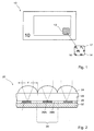
- FIG. 1 shows a schematic representation of a banknote 10, which is provided with a security element according to the invention in the form of a glued transfer element 12.
- the transfer element 12 represents a moiré magnification arrangement which presents a target image 14 to the viewer.
- the target image 14 shows a motif that is formed by visually recognizable and contrasting image areas 16 and 17, respectively.
- the motif of the target image is formed by shiny metallic, dark appearing letters "PL” in front of a likewise shiny metallic, but bright appearing background (shown here by the black letters "PL” in front of white background). It is understood that in practice mostly complex motifs, for example the denomination of the banknote, geometric patterns, portraits, architectural, technical or nature motives are used. The motifs can also be present in particular in the form of screened half-tone representations.
- the invention is not limited in any way to Moire magnification arrangements.
- the invention can be applied to all display arrangements with a contrasting reflective motif layer, in particular also in moire-type magnification arrangements, modulo magnification arrangements, or also in change pictures, motion pictures, pump pictures, morph pictures or stereo pictures of unscaled representing systems.
- the invention is also not limited to the banknote transfer elements used for illustration, but may also be used, for example, in security threads, wide security strips or cover sheets placed over a window area or through opening of a document.
- the microlenses or the reflective facets are applied to or introduced into different sides of an at least partially transparent banknote substrate, for example a substrate made of polymeric material.
- FIG. 2 schematically shows the structure of a security element 20 according to the invention, for example a transfer element, in cross section. Shown here are, as in the other figures, only necessary for the explanation of the principle of operation parts of the structure.
- the security element 20 of Fig. 2 has a carrier 22 in the form of a transparent plastic film, for example, about 20 microns thick PET film.
- the microlenses 24 form on the surface of the carrier film 22 a two-dimensional Bravais grid with a preselected symmetry.
- the Bravais grating for example, have a hexagonal lattice symmetry. However, other, in particular lower symmetries and thus more general forms, such as the symmetry of a parallelogram grating, are also possible. There may also be regions of different symmetries or Bravais lattice.
- a motif layer 26 is formed, which contains a divided into a plurality of unit cells 28 motif image with microimage regions 29A and 29B.
- the arrangement of the unit cells 28 also forms a two-dimensional Bravais grating with a preselected symmetry.
- the Bravais grating of the unit cells 28 differs slightly in its orientation and / or in the size of its grating parameters from the Bravais grating of the microlenses 24. Depending on the nature and size of the difference arises when viewing the motif image an enlarged picture of the microimage areas.
- the optical thickness of the carrier film 22 and the focal length of the microlenses 24 are matched to one another such that the motif layer 26 is located approximately at a distance from the lens focal length or in the focal plane.
- the carrier foil 22 thus forms an optical spacer layer which ensures a desired, constant spacing of the microlenses 24 and the motif layer 26 with the motif image.
- the motif image 26 When the motif image 26 is viewed with the lenticular grid, the motif is reconstructed from the imaged microimage regions 29A, 29B arranged in the unit cells 28, whereby the motif can float in front of and / or behind the image plane or lie in the image plane, depending on the design of the representation arrangement.
- the security element 20 typically includes further layers 32, such as protective, masking or other functional layers, which are not essential to the present invention and therefore will not be described further.
- a protective layer (not shown here) may also be provided on the microlenses, the refractive index of which preferably deviates by at least 0.3 from the refractive index of the microlenses.
- Moire magnification arrangements showing different colored motifs are known.
- the motif parts lying in the individual microimage regions 29A, 29B are printed, for example, in the desired shape.
- the peculiarity of the depiction arrangements described here consists in the fact that the motif of the target image 14 is formed by contrasting, differently reflecting image areas 16, 17.
- those in the individual microimage areas 29A, 29B lying subject parts of the target image 14 according to the invention formed by differently oriented reliefs. In order to ensure a sufficient contrast, the procedure is as follows.
- FIGS. 3 to 7 The structure and the basic mode of operation of a security element 20 according to the invention, for example of the transfer element 12 of FIG Fig. 1 , is now referring to the FIGS. 3 to 7 described in more detail.
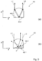
- FIG. 3 the basic structure of a representation arrangement 40 according to the invention is shown.
- idealized (spherical or cylindrical) lenses the beam path of the right or left marginal rays for the case of vertical incidence of light (corresponding to vertical plan view) is shown by way of example. It is further assumed that the micromirrors are located in the focal plane of the lenses.
- sections of the display assembly 40 are each arranged under a microlens, formed as micromirrors facets 42-1 and 42-2 of a first and a second type shown in a section through the yz plane.
- the micromirrors 42 - 1, 42 - 2 each have a reflection surface 44 - 1, 44 - 2, which is the optically effective surface of the facet and whose orientation is determined by the indication of the inclination.
- Fig. 3 (a) shows the case that the reflection surface 44-2 of the micromirror 42-2 is not inclined against the surface of the lens assembly. For the micromirror shown ⁇ is therefore equal to zero.
- the incident radiation (light rays L1, L2) in this case is reflected in the same direction from which it entered.
- the light beams L1, L2 leave the lens assembly through the lens through which they have also fallen and are all reflected back in the same direction.
- the reflection surface of the micromirror 42-1 is against the surface of the lens arrangement (and in the case of cylindrical lenses perpendicular to the longitudinal direction of the cylindrical lenses or in the direction of curvature of the cylindrical lenses) with the inclination
- the inclination ⁇ of the micromirror 42-1 has no influence on the direction of propagation in this part of the radiation (see light beam L1: after leaving the lens, the propagation direction essentially corresponds to the propagation direction of the radiation in the direction of propagation FIG. 3 (a) illustrated case, wherein the light beam L1 exits only slightly offset in comparison).
- some of the radiation here the light beam L2 passes the lens after reflection at the micromirror 42-1 and exits the arrangement for example through an adjacent lens.
- the propagation direction of the light beams is changed.
- the light beam L2 propagates in a direction determined by refraction at the surface of the first lens, tilt of the micromirror with respect to the surface of the lens assembly, and refraction at the surface of an adjacent (and not shown) second lens.
- the area of facet 42-1 or the area of facet 42-2 appears lighter or darker depends ultimately on how the environment is illuminated.
- An observer looks into a solid angle of the environment that is more or less fanned out by refraction of the light rays on the surface of the lenses, reflection on the facets and refraction on the surface of the lenses.
- the brightness of the environment in this solid angle range dictates whether the associated area appears bright or dark to the viewer.
- the larger the solid angle range the larger the range over which the brightness of the environment is practically averaged and the weaker the contrast.
- the beam path of the rays which are incident perpendicularly in the center or in the edge region of the lens is shown (light rays L3, L4, L5). It is further assumed that the micromirror or the facet 42-1 is located in the focal plane of the (idealized spherical) lens 24.
- a micromirror must be inclined at approximately the angle ⁇ * to the horizontal, so that the light rays L3, L4, L5 incident through the overlying microlens 24 (perpendicularly) no longer return there, but are deflected into an area adjacent to this lens.
- f the focal length of the microlens
- h the height of the microlens at the apex
- R the radius of curvature in the center of the microlens
- r the lens radius of the microlens.
- the reflective facets of the first type can according to the invention also have an inclination ⁇ 1 which deviates by less than ⁇ 15% from ⁇ *.
- the use of reflective facets with inclinations greater than ⁇ 1 can at least no longer substantially increase the contrast with respect to facets of a second type with a lower inclination ⁇ 2 or with an inclination ⁇ 2 equal to zero. Also, the use of such reflective facets - with significantly larger inclinations - be associated with difficulties in manufacturing.
- the reflective facets of the second type have according to the invention an inclination ⁇ 2 , which is given by
- the motif image 26 is composed according to the invention of a plurality of identical unit cells 28, of which some in some FIG. 5 are shown in a schematic manner, wherein, as in the other figures, only the parts of the structure required for the explanation of the principle of operation are shown.
- the unit cells 28 of the motif image 26, as explained above, are arranged next to one another in a grid, matching the grid of the microlenses 24.
- unit cells 28 are arranged here for the sake of simplicity as well as the microlenses 24 in a hexagonal grid.
- the motif image 26 contains two types of reflective facets 33-1 and 33-2, which differ in their orientation and, when viewed with the lenticular grid, produce the visually recognizable, contrasting image areas of the target image 14.
- the facets 33-1 form a first microimage region 29A, for example a foreground
- the facets 33-2 form a second microimage region 29B, for example a background.
- the invention is not limited to the subdivision into two types of facets. Rather, other types of facets may be provided with different orientation, for example, to produce different light-dark effects or to generate a grayscale image.
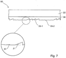
- FIG. 6 is the sectional view taken along the line VI-VI of FIG. 5 represented, wherein the representation in FIG. 6 as well as in the other figures is not true to scale, but partly greatly exaggerated for better presentation. Furthermore, to simplify the illustration in FIG. 6 as well as in FIG. 7 an optional existing reflective or high refractive coating on the facets 33-1, 33-2 not shown.
- the motif layer comprises a stamping layer 36 applied to the carrier 22, in which the reflective facets 33-1, 33-2 are formed.
- the embossed layer 36 structured in this way is preferably coated with a reflective or reflection-enhancing coating.
- a metal for example aluminum, can be vapor-deposited over the full area, so that a full-surface metal coating is formed.
- the inclination ⁇ 1 is the same for all facets 33-1 and in the exemplary embodiment is 21 °.
- the grating period of the facets 33-1 forming a periodic sawtooth grid is preferably between 2.5 ⁇ m and 100 ⁇ m and in particular between 3 ⁇ m and 20 ⁇ m. For example, the grating period is 4 ⁇ m.
- the inclination ⁇ 2 of the facets 33-2 of the second type is 0 °.
- the facets 33-1 form a foreground, here the letter "A", the facets 33-2 a background.
- the facets 33-1 or the facets 33-2 appear bright when viewed through the lenticular.
- the viewer can therefore perceive a contrast change in the subject, ie previously bright-appearing image areas of the subject then appear dark, previously dark appearing image areas of the subject appear bright after tilting.
- the grating period and the phase of the grating are identical for each unit cell 28, respectively, as shown in FIGS.
- the grating period of the facets 33 - 1 can also continue over all the unit cells 28 with the same phase, which, for example, prevents unwanted effects caused by moire magnification of the boundaries of the facets 33 - 1.
- FIG. 7 shows another way to increase the light-dark contrast.
- the second image area of the target image 14 can also be formed by a plurality of reflective facets 33-2.
- the reflective facets 33-2 can have different orientations, whereby a kind of glittering effect can be realized.
- the facets 33-2 differ in their inclinations ⁇ 2 .
- the inclinations ⁇ 2 of the facets 33-2 must also be at least 10 ° smaller than those of the facets 33-1 and may for example be between 0 ° and 5 °
- the inclination ⁇ 1 of the first type facets 33-1 is the same for all facets 33-1 and is 23 °, for example.
- the azimuth angle of the facets 33-2 of the second type may additionally or alternatively also vary.
- the inclination ⁇ 2 and / or the azimuth angle of Reflective facets 33-2 of the second type at least partially on a substantially random variation and therefore reflect light in different directions slightly different from the light incident direction. The glittering effect thus produced further increases the contrast with the reflective facets 33-1.
- the reflective or reflection-enhancing coating can also be present only in regions, in particular in the form of patterns, characters or a coding.
- the facets provided with a metal coating can be partially metallized or demetallized in the form of a symbol or a value number.
- the regional removal of the reflective or reflection-enhancing coating in the individual partial surfaces can, for example, also be effected by laser ablation of the coating through the lenses.
- a part of the facets may additionally be provided with a further, finer structuring.
- Such structuring is formed, for example, by nanostructuring, in particular by colored subwavelength structures which reflect into the zeroth diffraction order.
- other structures such as nanostructures such as moth-eye structures, or diffractive microrelief structures carrying holographic information are also possible.
- the reflectivity of the facets 33-2 of the second type can be advantageously influenced by non-diffractive matt structures, while the use of a nanostructuring such as, for B. moth-eye structures in the facets 33-1 of the first type has proved advantageous.
Claims (20)
- Élément de sécurité (20) pour la protection de papiers de sécurité, de documents de valeur et d'autres supports de données, comprenant un dispositif de représentation pour la représentation d'une ou de plusieurs images de consigne (14), dont les motifs sont formés respectivement par des zones d'image (16, 17) contrastantes et reconnaissables visuellement, dans lequel- le dispositif de représentation comprend un réseau de lentilles et une image à motif espacée du réseau de lentilles, montrant les images de consigne (14) prédéfinies lors d'une observation avec le réseau de lentilles, dans lequel- le réseau de lentilles est constitué d'une pluralité de microlentilles (24) sphériques ou asphériques, et- l'image à motif est constituée d'une pluralité de cellules élémentaires,caractérisé en ce que- l'image à motif comporte une pluralité de facettes réfléchissantes (33-1, 33-2) d'au moins un premier et un deuxième type, lesquelles se distinguent quant à leur inclinaison et produisent les images de consigne (14) contrastantes et reconnaissables visuellement lors d'une observation avec le réseau de lentilles, où- les facettes réfléchissantes du premier type (33-1) présentent une inclinaison β1 donnée paroù f représente la distance focale de la microlentille (24), R le rayon de courbure au centre de la microlentille (24) et r le rayon de lentille de la microlentille (24), et

 - les facettes réfléchissantes du deuxième type (33-2) présentent une inclinaison β2 donnée par |β 1 - β 2| > 10°.
 - Élément de sécurité (20) pour la protection de papiers de sécurité, de documents de valeur et d'autres supports de données, comprenant un dispositif de représentation pour la représentation d'une ou de plusieurs images de consigne (14) dont les motifs sont formés respectivement par des zones d'image (16, 17) contrastantes et reconnaissables visuellement, dans lequel- le dispositif de représentation comprend un réseau de lentilles et une image à motif espacée du réseau de lentilles, montrant les images de consigne (14) prédéfinies lors d'une observation avec le réseau de lentilles, dans lequel- le réseau de lentilles est constitué d'une pluralité de microlentilles (24) cylindriques disposées dans un réseau formant un système de coordonnées avec un premier axe de coordonnées déterminé par les lignes de points focaux des microlentilles cylindriques, et avec un deuxième axe de coordonnées s'étendant perpendiculairement au premier axe de coordonnées,- l'image à motif est constituée d'une pluralité de cellules élémentaires (28),caractérisé en ce que- l'image à motif comporte une pluralité de facettes réfléchissantes (33-1, 33-2) d'au moins un premier et un deuxième type, lesquelles se distinguent quant à leur inclinaison et produisent les images de consigne (14) contrastantes et reconnaissables visuellement lors d'une observation avec le réseau de lentilles, où- les facettes réfléchissantes du premier type (33-1) présentent une inclinaison, dont les composantes β1 dans la direction du deuxième axe de coordonnées sont données paroù f représente la distance focale de la microlentille (24), R le rayon de courbure au centre de la microlentille cylindrique (24) et r le rayon de lentille de la microlentille cylindrique (24), et

 - les facettes réfléchissantes du deuxième type (33-2) présentent une inclinaison dont les composantes β2 dans la direction du deuxième axe de coordonnées sont données par |β 1 - β 2| > 10°.
 - Élément de sécurité selon la revendication 1 ou 2, caractérisé en ce que l'inclinaison β2 des facettes réfléchissantes du deuxième type est donnée par |β 1 - β 2| > 15°, où l'inclinaison β2 des facettes réfléchissantes du deuxième type est de préférence égale à zéro.
- Élément de sécurité selon l'une des revendications précédentes, caractérisé en ce que les facettes réfléchissantes en particulier du premier type forment une grille de dents de scie périodique ou apériodique.
- Élément de sécurité selon la revendication 4, caractérisé en ce que la période de grille des facettes réfléchissantes est comprise entre 2,5 µm et 100 µm, de préférence entre 3 µm et 15 µm.
- Élément de sécurité selon la revendication 4 ou 5, caractérisé en ce que la période de grille des facettes réfléchissantes du premier et/ou du deuxième type se poursuit respectivement sur toutes les cellules élémentaires avec la même phase, ou en ce que la période de grille et la phase de la grille des facettes réfléchissantes du premier et/ou du deuxième type sont identiques pour toutes les cellules élémentaires, ou en ce que la période de grille et/ou la phase des facettes réfléchissantes du premier et/ou du deuxième type sont différentes d'une cellule élémentaire à l'autre.
- Élément de sécurité selon la revendication 6, caractérisé en ce que la période de grille et/ou la phase des facettes réfléchissantes du premier et/ou du deuxième type présentent au moins par endroits une variation essentiellement aléatoire.
- Élément de sécurité selon l'une des revendications précédentes, caractérisé en ce que les facettes réfléchissantes du premier et/ou du deuxième type présentent plusieurs facettes avec la même inclinaison pour chaque cellule élémentaire.
- Élément de sécurité selon l'une des revendications précédentes, caractérisé en ce que l'inclinaison, l'angle azimutal, la profondeur de structure et/ou éventuellement la période de grille des facettes réfléchissantes du deuxième type présentent au moins par endroits une variation essentiellement aléatoire.
- Élément de sécurité selon l'une des revendications précédentes, caractérisé en ce que les facettes réfléchissantes sont conçues comme des pièces de surface essentiellement planes.
- Élément de sécurité selon l'une des revendications précédentes, caractérisé en ce que les facettes réfléchissantes présentent une profondeur de structure de 0 µm à 10 µm, de préférence de 1,5 µm à 4 µm.
- Élément de sécurité selon l'une des revendications précédentes, caractérisé en ce que le diamètre des microlentilles sphériques ou asphériques ou l'expansion des microlentilles cylindriques mesure entre 5 µm et 100 µm, de préférence entre 10 µm et 30 µm dans la direction transversale.
- Élément de sécurité selon l'une des revendications 2 à 12, caractérisé en ce que l'expansion des microlentilles cylindriques dans la direction du premier axe de coordonnées mesure plus de 250 µm, de préférence plus de 500 µm, de façon particulièrement préférentielle plus de 2 mm.
- Élément de sécurité selon l'une des revendications précédentes, caractérisé en ce qu'un revêtement réfléchissant ou augmentant la réflexion est formé au moins par endroits sur les facettes réfléchissantes, en particulier en ce que le revêtement réfléchissant ou augmentant la réflexion est formé au moins par endroits, de préférence sous la forme de motifs, de signes ou d'un codage.
- Élément de sécurité selon l'une des revendications précédentes, caractérisé en ce qu'un revêtement à effet chatoyant est formé au moins par endroits sur les facettes réfléchissantes.
- Élément de sécurité selon l'une des revendications précédentes, caractérisé en ce que sur une partie des facettes réfléchissantes, il est prévu une structuration supplémentaire, de préférence une structure diffractive, une structure avec un effet matifiant ou dispersant et/ou une nanostructuration.
- Élément de sécurité selon l'une des revendications précédentes, caractérisé en ce que l'élément de sécurité est un fil de sécurité, un fil de déchirure, un ruban de sécurité, une bande de sécurité, un patch de sécurité ou une étiquette destinée à être collée sur un papier de sécurité, un document de valeur ou autre.
- Support de données avec un élément de sécurité selon l'une des revendications 1 à 17.
- Procédé pour la fabrication d'un élément de sécurité (20) avec un dispositif de représentation pour la représentation d'une ou de plusieurs images de consigne (14), dont les motifs sont formés respectivement par des zones d'image (16, 17) contrastantes et reconnaissables visuellement, dans lequel- pour la fabrication d'un dispositif de représentation, une image à motif est disposée à distance d'un réseau de lentilles, de manière à ce que l'image à motif montre les images de consigne (14) prédéfinies lors d'une observation avec le réseau de lentilles, dans lequel- le réseau de lentilles est constitué d'une pluralité de microlentilles (24) sphériques ou asphériques, et- l'image à motif est constituée d'une pluralité de cellules élémentaires (28), l'image à motif comportant une pluralité de facettes réfléchissantes (33-1, 33-2) d'au moins un premier et un deuxième type, lesquelles se distinguent quant à leur inclinaison et produisent les zones d'image contrastantes et reconnaissables visuellement des images de consigne (14) lors d'une observation avec le réseau de lentilles, où- les facettes réfléchissantes du premier type (33-1) présentent une inclinaison β1 donnée paroù f représente la distance focale de la microlentille (24), R le rayon de courbure au centre de la microlentille (24) et r le rayon de lentille de la microlentille (24), et

 - les facettes réfléchissantes du deuxième type (33-2) présentent une inclinaison β2 donnée par |β 1 - β 2| > 10°.
 - Procédé pour la fabrication d'un élément de sécurité (20) avec un dispositif de représentation pour la représentation d'une ou de plusieurs images de consigne (14), dont les motifs sont formés respectivement par des zones d'image (16, 17) contrastantes et reconnaissables visuellement, dans lequel- pour la fabrication d'un dispositif de représentation, une image à motif est disposée à distance d'un réseau de lentilles, de manière à ce que l'image à motif montre les images de consigne (14) prédéfinies lors d'une observation avec le réseau de lentilles, dans lequel- le réseau de lentilles est constitué d'une pluralité de microlentilles (24) cylindriques disposées dans un réseau formant un système de coordonnées avec un premier axe de coordonnées déterminé par les lignes de points focaux des microlentilles cylindriques, et avec un deuxième axe de coordonnées s'étendant perpendiculairement au premier axe de coordonnées,- l'image à motif est constituée d'une pluralité de cellules élémentaires (28), l'image à motif comportant une pluralité de facettes réfléchissantes (33-1, 33-2) d'au moins un premier et un deuxième type, lesquelles se distinguent quant à leur inclinaison et produisent les zones d'image contrastantes et reconnaissables visuellement des images de consigne (14) lors d'une observation avec le réseau de lentilles, où- les facettes réfléchissantes du premier type (33-1) présentent une inclinaison, dont les composantes β1 dans la direction du deuxième axe de coordonnées sont données paroù f représente la distance focale de la microlentille (24), R le rayon de courbure au centre de la microlentille cylindrique (24) et r le rayon de lentille de la microlentille cylindrique (24), et

 - les facettes réfléchissantes du deuxième type (33-2) présentent une inclinaison dont les composantes β2 dans la direction du deuxième axe de coordonnées sont données par |β 1 - β 2| > 10°.
Applications Claiming Priority (1)
| Application Number | Priority Date | Filing Date | Title |
|---|---|---|---|
| DE102013016041.3A DE102013016041A1 (de) | 2013-09-26 | 2013-09-26 | Sicherheitselement mit Linsenrasterbild |
Publications (2)
| Publication Number | Publication Date |
|---|---|
| EP2853411A1 EP2853411A1 (fr) | 2015-04-01 |
| EP2853411B1 true EP2853411B1 (fr) | 2018-01-10 |
Family
ID=51627916
Family Applications (1)
| Application Number | Title | Priority Date | Filing Date |
|---|---|---|---|
| EP14003244.2A Active EP2853411B1 (fr) | 2013-09-26 | 2014-09-18 | Élément de sécurité avec image lenticulaire |
Country Status (2)
| Country | Link |
|---|---|
| EP (1) | EP2853411B1 (fr) |
| DE (1) | DE102013016041A1 (fr) |
Families Citing this family (9)
| Publication number | Priority date | Publication date | Assignee | Title |
|---|---|---|---|---|
| WO2016065331A2 (fr) | 2014-10-24 | 2016-04-28 | Wavefront Technology, Inc. | Produits optiques, gabarits pour la fabrication de produits optiques, et procédés de fabrication de gabarits et de produits optiques |
| CA2992060A1 (fr) | 2015-07-13 | 2017-01-19 | Wavefront Technology, Inc. | Produits optiques, gabarits pour la fabrication de produits optiques, et procedes de fabrication de gabarits et de produits optiques |
| US10850550B2 (en) | 2016-04-22 | 2020-12-01 | Wavefront Technology, Inc. | Optical switch devices |
| CA3073365A1 (fr) | 2017-10-20 | 2019-04-25 | Wavefront Technology, Inc. | Dispositifs commutateurs optiques |
| EP3938216A4 (fr) | 2019-04-19 | 2022-12-07 | Wavefront Technology, Inc. | Dispositifs commutateurs optiques |
| CN112572019B (zh) * | 2019-09-30 | 2022-03-01 | 中钞特种防伪科技有限公司 | 光学防伪元件及防伪产品 |
| DE102019007417A1 (de) | 2019-10-24 | 2021-04-29 | Giesecke+Devrient Currency Technology Gmbh | Sicherheitselement mit maschinenlesbarem IR-Code |
| DE102019007418A1 (de) | 2019-10-24 | 2021-04-29 | Giesecke+Devrient Currency Technology Gmbh | Sicherheitselement und Wertdokument mit visuell und maschinell prüfbaren Sicherheitsmerkmalen, die in räumlicher Beziehung zueinander stehen |
| CN112848742A (zh) * | 2019-11-27 | 2021-05-28 | 中钞特种防伪科技有限公司 | 光学防伪元件及光学防伪产品 |
Family Cites Families (6)
| Publication number | Priority date | Publication date | Assignee | Title |
|---|---|---|---|---|
| US4417784A (en) | 1981-02-19 | 1983-11-29 | Rca Corporation | Multiple image encoding using surface relief structures as authenticating device for sheet-material authenticated item |
| DE102005062132A1 (de) | 2005-12-23 | 2007-07-05 | Giesecke & Devrient Gmbh | Sicherheitselement |
| DE102007029203A1 (de) | 2007-06-25 | 2009-01-08 | Giesecke & Devrient Gmbh | Sicherheitselement |
| DE102008062475A1 (de) * | 2008-12-16 | 2010-06-17 | Giesecke & Devrient Gmbh | Sicherheitselement und Sicherheitspapier |
| DE102010047250A1 (de) * | 2009-12-04 | 2011-06-09 | Giesecke & Devrient Gmbh | Sicherheitselement, Wertdokument mit einem solchen Sicherheitselement sowie Herstellungsverfahren eines Sicherheitselementes |
| DE102010019766A1 (de) | 2010-05-07 | 2011-11-10 | Giesecke & Devrient Gmbh | Verfahren zur Erzeugung einer Mikrostruktur auf einem Träger |
-
2013
- 2013-09-26 DE DE102013016041.3A patent/DE102013016041A1/de not_active Withdrawn
-
2014
- 2014-09-18 EP EP14003244.2A patent/EP2853411B1/fr active Active
Non-Patent Citations (1)
| Title |
|---|
| None * |
Also Published As
| Publication number | Publication date |
|---|---|
| DE102013016041A1 (de) | 2015-03-26 |
| EP2853411A1 (fr) | 2015-04-01 |
Similar Documents
| Publication | Publication Date | Title |
|---|---|---|
| EP2853411B1 (fr) | Élément de sécurité avec image lenticulaire | |
| EP3216620B1 (fr) | Élement de securite, document de valeur dote d'un tel element de securite ainsi que procede de fabrication d'un element de securite | |
| EP2040934B1 (fr) | Élément de sécurité | |
| EP2451650B2 (fr) | Corps multicouche | |
| EP2934904B1 (fr) | Élément de sécurité avec une image lenticulaire | |
| EP1853763B2 (fr) | Element de securite et procede de production de cet element | |
| EP3339048B1 (fr) | Élément de sécurité ayant une zone de surface réfléchissante | |
| DE102007023560B4 (de) | Mehrschichtkörper | |
| EP3291997B1 (fr) | Élément de sécurité optiquement variable | |
| EP2773514B1 (fr) | Élément de sécurité optiquement variable | |
| EP2951031B1 (fr) | Élément de sécurité pourvu d'éléments structuraux en forme de rainure ou de nervure | |
| DE102008046128B4 (de) | Optisch variables Sicherheitselement mit Mattbereich | |
| EP2385902B1 (fr) | Élément de sécurité et papier de sécurité | |
| DE102009022612A1 (de) | Sicherheitselement, Sicherheitssystem und Herstellungsverfahren dafür | |
| EP2889152B1 (fr) | Élément de sécurité destiné à représenter au moins une information variable optiquement | |
| DE102010050031A1 (de) | Sicherheitselement und Verfahren zur Herstellung eines Sicherheitselements | |
| EP2897812B1 (fr) | Élément de sécurité à système de visualisation | |
| DE102016007784A1 (de) | Optisch variables Sicherheitselement | |
| EP3606765B1 (fr) | Elément de sécurité avec structure en relief et son procédé de fabrication | |
| EP3648983B1 (fr) | Système de sécurité optiquement variable |
Legal Events
| Date | Code | Title | Description |
|---|---|---|---|
| PUAI | Public reference made under article 153(3) epc to a published international application that has entered the european phase |
Free format text: ORIGINAL CODE: 0009012 |
|
| 17P | Request for examination filed |
Effective date: 20140918 |
|
| AK | Designated contracting states |
Kind code of ref document: A1 Designated state(s): AL AT BE BG CH CY CZ DE DK EE ES FI FR GB GR HR HU IE IS IT LI LT LU LV MC MK MT NL NO PL PT RO RS SE SI SK SM TR |
|
| AX | Request for extension of the european patent |
Extension state: BA ME |
|
| R17P | Request for examination filed (corrected) |
Effective date: 20151001 |
|
| RBV | Designated contracting states (corrected) |
Designated state(s): AL AT BE BG CH CY CZ DE DK EE ES FI FR GB GR HR HU IE IS IT LI LT LU LV MC MK MT NL NO PL PT RO RS SE SI SK SM TR |
|
| GRAP | Despatch of communication of intention to grant a patent |
Free format text: ORIGINAL CODE: EPIDOSNIGR1 |
|
| RIC1 | Information provided on ipc code assigned before grant |
Ipc: B42D 25/324 20140101ALI20170703BHEP Ipc: B42D 25/342 20140101ALI20170703BHEP Ipc: B42D 25/373 20140101ALI20170703BHEP Ipc: B42D 25/29 20140101AFI20170703BHEP |
|
| RAP1 | Party data changed (applicant data changed or rights of an application transferred) |
Owner name: GIESECKE+DEVRIENT CURRENCY TECHNOLOGY GMBH |
|
| INTG | Intention to grant announced |
Effective date: 20170726 |
|
| GRAS | Grant fee paid |
Free format text: ORIGINAL CODE: EPIDOSNIGR3 |
|
| GRAA | (expected) grant |
Free format text: ORIGINAL CODE: 0009210 |
|
| AK | Designated contracting states |
Kind code of ref document: B1 Designated state(s): AL AT BE BG CH CY CZ DE DK EE ES FI FR GB GR HR HU IE IS IT LI LT LU LV MC MK MT NL NO PL PT RO RS SE SI SK SM TR |
|
| REG | Reference to a national code |
Ref country code: CH Ref legal event code: EP Ref country code: AT Ref legal event code: REF Ref document number: 961952 Country of ref document: AT Kind code of ref document: T Effective date: 20180115 |
|
| REG | Reference to a national code |
Ref country code: IE Ref legal event code: FG4D Free format text: LANGUAGE OF EP DOCUMENT: GERMAN |
|
| REG | Reference to a national code |
Ref country code: DE Ref legal event code: R096 Ref document number: 502014006924 Country of ref document: DE Ref country code: CH Ref legal event code: NV Representative=s name: RENTSCH PARTNER AG, CH |
|
| REG | Reference to a national code |
Ref country code: NL Ref legal event code: MP Effective date: 20180110 |
|
| PG25 | Lapsed in a contracting state [announced via postgrant information from national office to epo] |
Ref country code: NL Free format text: LAPSE BECAUSE OF FAILURE TO SUBMIT A TRANSLATION OF THE DESCRIPTION OR TO PAY THE FEE WITHIN THE PRESCRIBED TIME-LIMIT Effective date: 20180110 |
|
| PG25 | Lapsed in a contracting state [announced via postgrant information from national office to epo] |
Ref country code: ES Free format text: LAPSE BECAUSE OF FAILURE TO SUBMIT A TRANSLATION OF THE DESCRIPTION OR TO PAY THE FEE WITHIN THE PRESCRIBED TIME-LIMIT Effective date: 20180110 Ref country code: LT Free format text: LAPSE BECAUSE OF FAILURE TO SUBMIT A TRANSLATION OF THE DESCRIPTION OR TO PAY THE FEE WITHIN THE PRESCRIBED TIME-LIMIT Effective date: 20180110 Ref country code: CY Free format text: LAPSE BECAUSE OF FAILURE TO SUBMIT A TRANSLATION OF THE DESCRIPTION OR TO PAY THE FEE WITHIN THE PRESCRIBED TIME-LIMIT Effective date: 20180110 Ref country code: FI Free format text: LAPSE BECAUSE OF FAILURE TO SUBMIT A TRANSLATION OF THE DESCRIPTION OR TO PAY THE FEE WITHIN THE PRESCRIBED TIME-LIMIT Effective date: 20180110 Ref country code: HR Free format text: LAPSE BECAUSE OF FAILURE TO SUBMIT A TRANSLATION OF THE DESCRIPTION OR TO PAY THE FEE WITHIN THE PRESCRIBED TIME-LIMIT Effective date: 20180110 Ref country code: NO Free format text: LAPSE BECAUSE OF FAILURE TO SUBMIT A TRANSLATION OF THE DESCRIPTION OR TO PAY THE FEE WITHIN THE PRESCRIBED TIME-LIMIT Effective date: 20180410 |
|
| PG25 | Lapsed in a contracting state [announced via postgrant information from national office to epo] |
Ref country code: GR Free format text: LAPSE BECAUSE OF FAILURE TO SUBMIT A TRANSLATION OF THE DESCRIPTION OR TO PAY THE FEE WITHIN THE PRESCRIBED TIME-LIMIT Effective date: 20180411 Ref country code: PL Free format text: LAPSE BECAUSE OF FAILURE TO SUBMIT A TRANSLATION OF THE DESCRIPTION OR TO PAY THE FEE WITHIN THE PRESCRIBED TIME-LIMIT Effective date: 20180110 Ref country code: RS Free format text: LAPSE BECAUSE OF FAILURE TO SUBMIT A TRANSLATION OF THE DESCRIPTION OR TO PAY THE FEE WITHIN THE PRESCRIBED TIME-LIMIT Effective date: 20180110 Ref country code: BG Free format text: LAPSE BECAUSE OF FAILURE TO SUBMIT A TRANSLATION OF THE DESCRIPTION OR TO PAY THE FEE WITHIN THE PRESCRIBED TIME-LIMIT Effective date: 20180410 Ref country code: LV Free format text: LAPSE BECAUSE OF FAILURE TO SUBMIT A TRANSLATION OF THE DESCRIPTION OR TO PAY THE FEE WITHIN THE PRESCRIBED TIME-LIMIT Effective date: 20180110 Ref country code: IS Free format text: LAPSE BECAUSE OF FAILURE TO SUBMIT A TRANSLATION OF THE DESCRIPTION OR TO PAY THE FEE WITHIN THE PRESCRIBED TIME-LIMIT Effective date: 20180510 Ref country code: SE Free format text: LAPSE BECAUSE OF FAILURE TO SUBMIT A TRANSLATION OF THE DESCRIPTION OR TO PAY THE FEE WITHIN THE PRESCRIBED TIME-LIMIT Effective date: 20180110 |
|
| REG | Reference to a national code |
Ref country code: FR Ref legal event code: PLFP Year of fee payment: 5 |
|
| PG25 | Lapsed in a contracting state [announced via postgrant information from national office to epo] |
Ref country code: MT Free format text: LAPSE BECAUSE OF FAILURE TO SUBMIT A TRANSLATION OF THE DESCRIPTION OR TO PAY THE FEE WITHIN THE PRESCRIBED TIME-LIMIT Effective date: 20180110 |
|
| REG | Reference to a national code |
Ref country code: DE Ref legal event code: R097 Ref document number: 502014006924 Country of ref document: DE |
|
| PG25 | Lapsed in a contracting state [announced via postgrant information from national office to epo] |
Ref country code: AL Free format text: LAPSE BECAUSE OF FAILURE TO SUBMIT A TRANSLATION OF THE DESCRIPTION OR TO PAY THE FEE WITHIN THE PRESCRIBED TIME-LIMIT Effective date: 20180110 Ref country code: EE Free format text: LAPSE BECAUSE OF FAILURE TO SUBMIT A TRANSLATION OF THE DESCRIPTION OR TO PAY THE FEE WITHIN THE PRESCRIBED TIME-LIMIT Effective date: 20180110 Ref country code: IT Free format text: LAPSE BECAUSE OF FAILURE TO SUBMIT A TRANSLATION OF THE DESCRIPTION OR TO PAY THE FEE WITHIN THE PRESCRIBED TIME-LIMIT Effective date: 20180110 |
|
| PLBE | No opposition filed within time limit |
Free format text: ORIGINAL CODE: 0009261 |
|
| STAA | Information on the status of an ep patent application or granted ep patent |
Free format text: STATUS: NO OPPOSITION FILED WITHIN TIME LIMIT |
|
| PG25 | Lapsed in a contracting state [announced via postgrant information from national office to epo] |
Ref country code: DK Free format text: LAPSE BECAUSE OF FAILURE TO SUBMIT A TRANSLATION OF THE DESCRIPTION OR TO PAY THE FEE WITHIN THE PRESCRIBED TIME-LIMIT Effective date: 20180110 Ref country code: SM Free format text: LAPSE BECAUSE OF FAILURE TO SUBMIT A TRANSLATION OF THE DESCRIPTION OR TO PAY THE FEE WITHIN THE PRESCRIBED TIME-LIMIT Effective date: 20180110 Ref country code: CZ Free format text: LAPSE BECAUSE OF FAILURE TO SUBMIT A TRANSLATION OF THE DESCRIPTION OR TO PAY THE FEE WITHIN THE PRESCRIBED TIME-LIMIT Effective date: 20180110 Ref country code: SK Free format text: LAPSE BECAUSE OF FAILURE TO SUBMIT A TRANSLATION OF THE DESCRIPTION OR TO PAY THE FEE WITHIN THE PRESCRIBED TIME-LIMIT Effective date: 20180110 |
|
| 26N | No opposition filed |
Effective date: 20181011 |
|
| PG25 | Lapsed in a contracting state [announced via postgrant information from national office to epo] |
Ref country code: SI Free format text: LAPSE BECAUSE OF FAILURE TO SUBMIT A TRANSLATION OF THE DESCRIPTION OR TO PAY THE FEE WITHIN THE PRESCRIBED TIME-LIMIT Effective date: 20180110 |
|
| PG25 | Lapsed in a contracting state [announced via postgrant information from national office to epo] |
Ref country code: MC Free format text: LAPSE BECAUSE OF FAILURE TO SUBMIT A TRANSLATION OF THE DESCRIPTION OR TO PAY THE FEE WITHIN THE PRESCRIBED TIME-LIMIT Effective date: 20180110 |
|
| REG | Reference to a national code |
Ref country code: BE Ref legal event code: MM Effective date: 20180930 |
|
| REG | Reference to a national code |
Ref country code: IE Ref legal event code: MM4A |
|
| PG25 | Lapsed in a contracting state [announced via postgrant information from national office to epo] |
Ref country code: LU Free format text: LAPSE BECAUSE OF NON-PAYMENT OF DUE FEES Effective date: 20180918 |
|
| PG25 | Lapsed in a contracting state [announced via postgrant information from national office to epo] |
Ref country code: IE Free format text: LAPSE BECAUSE OF NON-PAYMENT OF DUE FEES Effective date: 20180918 |
|
| PG25 | Lapsed in a contracting state [announced via postgrant information from national office to epo] |
Ref country code: BE Free format text: LAPSE BECAUSE OF NON-PAYMENT OF DUE FEES Effective date: 20180930 |
|
| PG25 | Lapsed in a contracting state [announced via postgrant information from national office to epo] |
Ref country code: TR Free format text: LAPSE BECAUSE OF FAILURE TO SUBMIT A TRANSLATION OF THE DESCRIPTION OR TO PAY THE FEE WITHIN THE PRESCRIBED TIME-LIMIT Effective date: 20180110 |
|
| PG25 | Lapsed in a contracting state [announced via postgrant information from national office to epo] |
Ref country code: PT Free format text: LAPSE BECAUSE OF FAILURE TO SUBMIT A TRANSLATION OF THE DESCRIPTION OR TO PAY THE FEE WITHIN THE PRESCRIBED TIME-LIMIT Effective date: 20180110 Ref country code: HU Free format text: LAPSE BECAUSE OF FAILURE TO SUBMIT A TRANSLATION OF THE DESCRIPTION OR TO PAY THE FEE WITHIN THE PRESCRIBED TIME-LIMIT; INVALID AB INITIO Effective date: 20140918 |
|
| PG25 | Lapsed in a contracting state [announced via postgrant information from national office to epo] |
Ref country code: MK Free format text: LAPSE BECAUSE OF NON-PAYMENT OF DUE FEES Effective date: 20180110 Ref country code: RO Free format text: LAPSE BECAUSE OF FAILURE TO SUBMIT A TRANSLATION OF THE DESCRIPTION OR TO PAY THE FEE WITHIN THE PRESCRIBED TIME-LIMIT Effective date: 20180110 |
|
| P01 | Opt-out of the competence of the unified patent court (upc) registered |
Effective date: 20230520 |
|
| PGFP | Annual fee paid to national office [announced via postgrant information from national office to epo] |
Ref country code: GB Payment date: 20230921 Year of fee payment: 10 Ref country code: AT Payment date: 20230915 Year of fee payment: 10 |
|
| PGFP | Annual fee paid to national office [announced via postgrant information from national office to epo] |
Ref country code: FR Payment date: 20230918 Year of fee payment: 10 Ref country code: DE Payment date: 20230930 Year of fee payment: 10 |
|
| PGFP | Annual fee paid to national office [announced via postgrant information from national office to epo] |
Ref country code: CH Payment date: 20231001 Year of fee payment: 10 |