EP2853282A1 - Guide wire - Google Patents
Guide wire Download PDFInfo
- Publication number
- EP2853282A1 EP2853282A1 EP14173724.7A EP14173724A EP2853282A1 EP 2853282 A1 EP2853282 A1 EP 2853282A1 EP 14173724 A EP14173724 A EP 14173724A EP 2853282 A1 EP2853282 A1 EP 2853282A1
- Authority
- EP
- European Patent Office
- Prior art keywords
- coil body
- guide wire
- coating film
- wires
- come
- Prior art date
- Legal status (The legal status is an assumption and is not a legal conclusion. Google has not performed a legal analysis and makes no representation as to the accuracy of the status listed.)
- Granted
Links
Images


Classifications
-
- A—HUMAN NECESSITIES
- A61—MEDICAL OR VETERINARY SCIENCE; HYGIENE
- A61M—DEVICES FOR INTRODUCING MEDIA INTO, OR ONTO, THE BODY; DEVICES FOR TRANSDUCING BODY MEDIA OR FOR TAKING MEDIA FROM THE BODY; DEVICES FOR PRODUCING OR ENDING SLEEP OR STUPOR
- A61M25/00—Catheters; Hollow probes
- A61M25/01—Introducing, guiding, advancing, emplacing or holding catheters
- A61M25/09—Guide wires
-
- A—HUMAN NECESSITIES
- A61—MEDICAL OR VETERINARY SCIENCE; HYGIENE
- A61M—DEVICES FOR INTRODUCING MEDIA INTO, OR ONTO, THE BODY; DEVICES FOR TRANSDUCING BODY MEDIA OR FOR TAKING MEDIA FROM THE BODY; DEVICES FOR PRODUCING OR ENDING SLEEP OR STUPOR
- A61M25/00—Catheters; Hollow probes
- A61M25/01—Introducing, guiding, advancing, emplacing or holding catheters
- A61M25/09—Guide wires
- A61M25/09016—Guide wires with mandrils
- A61M25/09033—Guide wires with mandrils with fixed mandrils, e.g. mandrils fixed to tip; Tensionable wires
-
- A—HUMAN NECESSITIES
- A61—MEDICAL OR VETERINARY SCIENCE; HYGIENE
- A61M—DEVICES FOR INTRODUCING MEDIA INTO, OR ONTO, THE BODY; DEVICES FOR TRANSDUCING BODY MEDIA OR FOR TAKING MEDIA FROM THE BODY; DEVICES FOR PRODUCING OR ENDING SLEEP OR STUPOR
- A61M25/00—Catheters; Hollow probes
- A61M25/01—Introducing, guiding, advancing, emplacing or holding catheters
- A61M25/09—Guide wires
- A61M2025/09058—Basic structures of guide wires
- A61M2025/09083—Basic structures of guide wires having a coil around a core
-
- A—HUMAN NECESSITIES
- A61—MEDICAL OR VETERINARY SCIENCE; HYGIENE
- A61M—DEVICES FOR INTRODUCING MEDIA INTO, OR ONTO, THE BODY; DEVICES FOR TRANSDUCING BODY MEDIA OR FOR TAKING MEDIA FROM THE BODY; DEVICES FOR PRODUCING OR ENDING SLEEP OR STUPOR
- A61M25/00—Catheters; Hollow probes
- A61M25/01—Introducing, guiding, advancing, emplacing or holding catheters
- A61M25/09—Guide wires
- A61M2025/09058—Basic structures of guide wires
- A61M2025/09083—Basic structures of guide wires having a coil around a core
- A61M2025/09091—Basic structures of guide wires having a coil around a core where a sheath surrounds the coil at the distal part
-
- A—HUMAN NECESSITIES
- A61—MEDICAL OR VETERINARY SCIENCE; HYGIENE
- A61M—DEVICES FOR INTRODUCING MEDIA INTO, OR ONTO, THE BODY; DEVICES FOR TRANSDUCING BODY MEDIA OR FOR TAKING MEDIA FROM THE BODY; DEVICES FOR PRODUCING OR ENDING SLEEP OR STUPOR
- A61M25/00—Catheters; Hollow probes
- A61M25/01—Introducing, guiding, advancing, emplacing or holding catheters
- A61M25/09—Guide wires
- A61M2025/09133—Guide wires having specific material compositions or coatings; Materials with specific mechanical behaviours, e.g. stiffness, strength to transmit torque
Definitions
- the present invention relates to a guide wire inserted into the lumen of a blood vessel or the like.
- a guide wire used when inserting a catheter into a blood vessel.
- the guide wire When inserting a catheter, first the guide wire is inserted into the blood vessel, and then the catheter is allowed to proceed along the guide wire. In such manner, the guide wire functions as a guide which guides the catheter to the lesion area.
- a guide wire commonly used is a so-called coil-type guide wire having the distal end portion of its core shaft covered with a coil body.
- a guide wire having the surface of its coil body covered with a coating film made of such as resin (Patent Literature 1).
- Patent Literature 1 U.S. Patent No. 5840046
- the present invention has been devised in light of the abovementioned problem exhibited by conventional technology and the object of the present invention is to provide technology that enables the coil body in a guide wire having the surface of its coil body covered with a coating film to be easily bendable.
- a guide wire uses the following configuration. Namely, a guide wire comprising a core shaft, a coil body which covers said core shaft, and a coating film which covers said coil body, wherein the guide wire is characterized in that said coating film is arranged to come between wires of the said coil body while gaps are formed between said wires and the portion where said coating film comes between said wires.
- the coating film which covers the coil body may be arranged such that the film comes between the wires to be deeper than the center of the wires of the coil body.
- the film thickness of the coating film in portions that come between the wires of the coil body may be less than the coating film thickness in the portions that exist on the surface of the coil body.
- the portions that exist on the surface of the coil body are easily worn due to contact with exterior items (such as the inner walls of blood vessels or lesions). Accordingly, due to the film thickness of such portions being greater, it is also possible to apply resistance in relation to such wear.
- Fig. 1 is an explanatory diagram illustrating the configuration of guide wire (1) according to the first embodiment of the present invention.
- Guide wire (1) is configured of such as core shaft (4) and coil body (5) which covers core shaft (4).
- the distal end portion of coil body (5) and the distal end portion of core shaft (4) are connected via joint (7) while the base end portion of coil body (5) and the middle portion of core shaft (4) are connected via joint (8).
- Coating film (10) is provided in order to ensure lubricity, when guide wire (1) is inserted into a blood vessel, by reducing the frictional resistance between the surface of guide wire (1) and the inner walls of the blood vessel. Therefore, it is preferable that coating portion (10) is formed of a material having low frictional resistance (such as a hydrophilic resin).
- coating portion (10) is formed with polyvinyl alcohol, polyvinyl pyrrrolidone, polyethylene glycol, polyacrylamide, polyacrylic acid, sodium polyacrylate, poly-(2-hydroxyethyl methacrylate), a maleic acid copolymer, an ethylene vinyl alcohol copolymer, a monomer of 2-methacryloyloxyehtyl phosphorylcholine or a copolymer thereof, a (2-hydroxyethyl methacrylate)-styrene block copolymer, various synthetic polypeptides, collagen, hyaluronic acid, a cellulose-based polymer, or a mixture of any of these.
- coating portion (10) may also be formed using a material where an additive such as a non-hydrophilic monomer, a cross-linking agent, a non-volatile solvent, a volatile solvent, or a surfactant is added to any of the abovementioned materials.
- an additive such as a non-hydrophilic monomer, a cross-linking agent, a non-volatile solvent, a volatile solvent, or a surfactant is added to any of the abovementioned materials.
- Fig. 2 is an enlarged view of coil body (5) and coating film (10) of guide wire (1) according to the first embodiment of the present invention.
- coil body (5) of guide wire (1) of this embodiment is formed such that adjacent wires (6) are not in contact with each other. In other words, the coil is formed in a state where the pitch of coil body (5) is spread out (open-coiled).
- coating film (10) on the surface of coil body (5) is arranged to come between the wires of coil body (5). Due to this configuration, coating film (10) is formed to be in a so-called bellows-shape.
- gaps (20) are formed between the wires (6) of coil body (5) and the portions where the coating film (10) comes into the gaps between the wires of coil body (5).
- the reason for providing such gaps (20) in the guide wire (1) of this embodiment is as explained below.
- guide wire (1) of this embodiment even with a configuration having coating film (10) on the surface of coil body (5), coil body (5) can be easily bent. For this reason, it becomes possible to ensure lubricity of guide wire (1) within the blood vessel while also enabling the guide wire to follow the shape of the blood vessel in which it is inserted.
- Fig. 3 is an enlarged view of coil body (5) and coating film (12) of guide wire (2) according to the second embodiment.
- Guide wire (2) of this embodiment differs from the abovementioned guide wire (1) of the first embodiment in the following aspects. Namely, as illustrated in Fig. 3 , coating film (12) which covers coil body (5) is, in relation to the gaps between the wires of coil body (5), arranged to come deeper than center (6c) of the wires (6). In other words, the depth of the drop of coating film (12) from the surface of coil body (5) is arranged to be greater than the radius of wire (6) of coil body (5).
- coating film (12) is, in relation to the gaps between the wires of coil body (5), arranged to come deeper than center (6c) of the wires (6), even in a case where coil body (5) is greatly bent (flexed), coating film (12) is prevented from being fully stretched. Accordingly, even in a case where guide wire (2) is inserted into a bent region of a blood vessel, it is possible to prevent coating film (12) from rupturing due to being fully stretched.
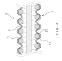
- Fig. 4 is an enlarged view of coil body (5) and coating film (13) of guide wire (3) according to the third embodiment.
- the film thickness of the coating films were explained as being uniform (refer to Fig. 2 and Fig. 3 ).
- the film thickness of coating film (13) differs depending on the portions. Namely, as illustrated in Fig. 4 , with guide wire (3) of this embodiment, the film thickness of coating film (13) in portions where the film comes between the wires of coil body (5) is less than the film thickness of coating film (13) in portions where the film exists on the surface of coil body (5).
- guide wire (3) of this embodiment it is possible for the guide wire to excellently follow an intricately tortuous blood vessel. This is due to the following reason.
- the portions that exist on the surface of coil body (5) come into contact with exterior items (such as the inner walls of blood vessels or lesions) more frequently than the portions that come into the gaps between the wires of coil body (5) and accordingly are more easily worn.
- exterior items such as the inner walls of blood vessels or lesions
- the film thickness is greater in the portions that are more subject to wear (portions that exist on the surface of coil body (5), it is also possible to improve the resistance of coating film (13) in relation to such wear.
- the present invention is not limited to the abovementioned embodiments and it is possible for the present invention to be implemented in various manners without departing from the gist thereof.
- the coating film was explained as not being configured to come further inward than the inner peripheral surface of the coil body (refer to Fig. 2 through Fig. 4 ).
- this coating film may be configured to be arranged in a further inward position than the inner peripheral surface of the coil body (drawing omitted).
- the coating film is arranged to not come too deep between the wires as this prevents the coating film from coming into contact with the core shaft when the guide wire is bent.
Landscapes
- Health & Medical Sciences (AREA)
- Life Sciences & Earth Sciences (AREA)
- Biophysics (AREA)
- Pulmonology (AREA)
- Engineering & Computer Science (AREA)
- Anesthesiology (AREA)
- Biomedical Technology (AREA)
- Heart & Thoracic Surgery (AREA)
- Hematology (AREA)
- Animal Behavior & Ethology (AREA)
- General Health & Medical Sciences (AREA)
- Public Health (AREA)
- Veterinary Medicine (AREA)
- Media Introduction/Drainage Providing Device (AREA)
- Surgical Instruments (AREA)
- Materials For Medical Uses (AREA)
Abstract
Description
- The present invention relates to a guide wire inserted into the lumen of a blood vessel or the like.
- Known is a guide wire used when inserting a catheter into a blood vessel. When inserting a catheter, first the guide wire is inserted into the blood vessel, and then the catheter is allowed to proceed along the guide wire. In such manner, the guide wire functions as a guide which guides the catheter to the lesion area.
- As such a guide wire, commonly used is a so-called coil-type guide wire having the distal end portion of its core shaft covered with a coil body. In addition, for the purpose of ensuring lubricity within the blood vessel, proposed is a guide wire having the surface of its coil body covered with a coating film made of such as resin (Patent Literature 1).
- [Patent Literature 1]
U.S. Patent No. 5840046 - However, with the abovementioned conventional guide wire, by covering the surface of the coil body with a coating film, there was the problem of the coil body (and consequently the guide wire) becoming difficult to bend.
- The present invention has been devised in light of the abovementioned problem exhibited by conventional technology and the object of the present invention is to provide technology that enables the coil body in a guide wire having the surface of its coil body covered with a coating film to be easily bendable.
- In order to solve the abovementioned problem, a guide wire according to the present invention uses the following configuration. Namely, a guide wire comprising a core shaft, a coil body which covers said core shaft, and a coating film which covers said coil body, wherein the guide wire is characterized in that said coating film is arranged to come between wires of the said coil body while gaps are formed between said wires and the portion where said coating film comes between said wires.
- In such a guidewire of the present invention, as the coating film is arranged to come between the wires of the coil body while gaps are formed between said wires and the portion where said coating film comes between said wires, it is possible for the coating film to easily bend when the coil body is bent. As a result, in the guide wire having the surface of its coil body covered with a coating film, the coil body (and consequently the guide wire) becomes easily bendable.
- In addition, in the abovementioned guide wire according to the present invention, the coating film which covers the coil body may be arranged such that the film comes between the wires to be deeper than the center of the wires of the coil body.
- In such a guidewire of the present invention, as the coating film is arranged to come deeper than the center of the wires of the coil body, even in a case where the coil body is greatly bent (flexed) the coating film is prevented from becoming fully stretched. As a result, in addition to the abovementioned effect (of the coil body becoming easily bendable), even in a case where the guide wire is inserted into a bent region of a blood vessel, it is possible to prevent the coating film from rupturing due to being fully stretched.
- In addition, although this will be described in detail later, due to the coating film being arranged to come deeper than the center of the wires of the coil body, it is also possible to improve the adhesion of the coating film and the coil body.
- In addition, in the abovementioned guide wire according to the present invention, the film thickness of the coating film in portions that come between the wires of the coil body may be less than the coating film thickness in the portions that exist on the surface of the coil body.
- In such a guidewire of the present invention, as the film thickness of the coating film in portions that come between the wires of the coil body is less than the film thickness of the portions that exist on the surface of the coil body, it becomes easier for the coating film to bend when the guide wire is bent. As a result, as the coil body (and consequently the guide wire) can be made to be more easily bendable, it is possible for the guide wire to excellently follow an intricately tortuous blood vessel.
- Furthermore, the portions that exist on the surface of the coil body are easily worn due to contact with exterior items (such as the inner walls of blood vessels or lesions). Accordingly, due to the film thickness of such portions being greater, it is also possible to apply resistance in relation to such wear.
-
- [
Fig. 1] Fig. 1 is an explanatory diagram illustrating the configuration of a guide wire according to the first embodiment of the present invention. - [
Fig. 2] Fig. 2 is an enlarged view of the coil body and the coating film of the guide wire according to the first embodiment of the present invention. - [
Fig. 3] Fig. 3 is an enlarged view of the coil body and the coating film of a guide wire according to the second embodiment of the present invention. - [
Fig. 4] Fig. 4 is an enlarged view of the coil body and the coating film of a guide wire according to the third embodiment of the present invention. - Various embodiments of a guide wire according to the present invention are explained below in order to clarify the details of the abovementioned present invention.
-
Fig. 1 is an explanatory diagram illustrating the configuration of guide wire (1) according to the first embodiment of the present invention. Guide wire (1) is configured of such as core shaft (4) and coil body (5) which covers core shaft (4). The distal end portion of coil body (5) and the distal end portion of core shaft (4) are connected via joint (7) while the base end portion of coil body (5) and the middle portion of core shaft (4) are connected via joint (8). - Furthermore, with guide wire (1) of this embodiment, the surface of coil body (5) is covered with coating film (10). Coating film (10) is provided in order to ensure lubricity, when guide wire (1) is inserted into a blood vessel, by reducing the frictional resistance between the surface of guide wire (1) and the inner walls of the blood vessel. Therefore, it is preferable that coating portion (10) is formed of a material having low frictional resistance (such as a hydrophilic resin). For example, it is preferable that coating portion (10) is formed with polyvinyl alcohol, polyvinyl pyrrrolidone, polyethylene glycol, polyacrylamide, polyacrylic acid, sodium polyacrylate, poly-(2-hydroxyethyl methacrylate), a maleic acid copolymer, an ethylene vinyl alcohol copolymer, a monomer of 2-methacryloyloxyehtyl phosphorylcholine or a copolymer thereof, a (2-hydroxyethyl methacrylate)-styrene block copolymer, various synthetic polypeptides, collagen, hyaluronic acid, a cellulose-based polymer, or a mixture of any of these.
- In addition, coating portion (10) may also be formed using a material where an additive such as a non-hydrophilic monomer, a cross-linking agent, a non-volatile solvent, a volatile solvent, or a surfactant is added to any of the abovementioned materials.
-
Fig. 2 is an enlarged view of coil body (5) and coating film (10) of guide wire (1) according to the first embodiment of the present invention. As illustrated in the drawing, coil body (5) of guide wire (1) of this embodiment is formed such that adjacent wires (6) are not in contact with each other. In other words, the coil is formed in a state where the pitch of coil body (5) is spread out (open-coiled). - Furthermore, coating film (10) on the surface of coil body (5) is arranged to come between the wires of coil body (5). Due to this configuration, coating film (10) is formed to be in a so-called bellows-shape.
- In this configuration, with guide wire (1) of this embodiment, gaps (20) are formed between the wires (6) of coil body (5) and the portions where the coating film (10) comes into the gaps between the wires of coil body (5). The reason for providing such gaps (20) in the guide wire (1) of this embodiment is as explained below.
- Namely, in a case where there is no gap between the wires of the coil body and the portions where the coating film come between the wires of the coil body (for example, in a case where the gaps are filled due to the film thickness of the coating film being rather thick), when the coil body is bent, tension is created on the coating film. As a result, since the coil body (and consequently the guide wire) is difficult to bend, this causes a negative effect where for example the ability of the guide wire to follow the shape of a blood vessel is lowered.
- On the other hand, with guide wire (1) of this embodiment, since gaps (20) are formed between the wires (6) of coil body (5) and the portions where coating film (10) comes between the wires of coil body (5), it is easy for coating film (10) to bend when coil body (5) is bent. As a result, it becomes possible for coil body (5) to be easily bent.
- As explained in the above, with guide wire (1) of this embodiment, even with a configuration having coating film (10) on the surface of coil body (5), coil body (5) can be easily bent. For this reason, it becomes possible to ensure lubricity of guide wire (1) within the blood vessel while also enabling the guide wire to follow the shape of the blood vessel in which it is inserted.
- Along with the abovementioned first embodiment, there exist other related embodiments. The following are brief explanations of these other embodiments. It shall be noted that in the following explanations, configurations that are identical to guide wire (1) of the first embodiment are denoted by the same reference numerals and detailed explanations thereof are omitted.
-
Fig. 3 is an enlarged view of coil body (5) and coating film (12) of guide wire (2) according to the second embodiment. Guide wire (2) of this embodiment, differs from the abovementioned guide wire (1) of the first embodiment in the following aspects. Namely, as illustrated inFig. 3 , coating film (12) which covers coil body (5) is, in relation to the gaps between the wires of coil body (5), arranged to come deeper than center (6c) of the wires (6). In other words, the depth of the drop of coating film (12) from the surface of coil body (5) is arranged to be greater than the radius of wire (6) of coil body (5). - Also In such a guidewire (2) of this embodiment, similar to the abovementioned guide wire (1) of the first embodiment, as gaps (20) are formed between the wires (6) of coil body (5) and the portions where coating film (12) come between the wires of coil body (5), it is possible for coil body (5) to be easily bent.
- In addition, with guide wire (2) of this embodiment, since coating film (12) is, in relation to the gaps between the wires of coil body (5), arranged to come deeper than center (6c) of the wires (6), even in a case where coil body (5) is greatly bent (flexed), coating film (12) is prevented from being fully stretched. Accordingly, even in a case where guide wire (2) is inserted into a bent region of a blood vessel, it is possible to prevent coating film (12) from rupturing due to being fully stretched.
- Furthermore, as illustrated in
Fig. 3 , with guide wire (2) of this embodiment, due to coating film (12) being, in relation to the gaps between the wires of coil body (5), arranged to come deeper than center (6c) of the wires (6), it is possible to ensure a sufficient contact area between coating film (12) and the wires (6) of coil body (5). As a result, it becomes possible to improve the adhesion of coating film (12) and coil body (5). -
Fig. 4 is an enlarged view of coil body (5) and coating film (13) of guide wire (3) according to the third embodiment. With the abovementioned guide wires of the first embodiment and the second embodiment, the film thickness of the coating films were explained as being uniform (refer toFig. 2 andFig. 3 ). Meanwhile, with guide wire (3) of this embodiment, the film thickness of coating film (13) differs depending on the portions. Namely, as illustrated inFig. 4 , with guide wire (3) of this embodiment, the film thickness of coating film (13) in portions where the film comes between the wires of coil body (5) is less than the film thickness of coating film (13) in portions where the film exists on the surface of coil body (5). - Also with such guide wire (3) of this embodiment, similar to the abovementioned guide wire (1) of the first embodiment and guide wire (2) of the second embodiment, as gaps (20) are formed between the wires (6) and the portions where coating film (13) comes between the wires of coil body (5), it is possible for coil body (5) to be easily bent.
- Furthermore, with guide wire (3) of this embodiment, it is possible for the guide wire to excellently follow an intricately tortuous blood vessel. This is due to the following reason.
- Namely, when coil body (5) is bent, although the portions that exist on the surface of coil body (5) are barely subject to deformation, the portions that come between the wires of coil body (5) are subject to deformation. Accordingly, by reducing the film thickness of coating film (13) in such portions that are subject to deformation, it becomes easier for coating film (13) to bend when coil body (5) is bent. As a result, since it becomes easier to bend coil body (5) (and consequently guide wire (3)), it becomes possible for the guide wire to excellently follow an intricately tortuous blood vessel.
- Meanwhile, the portions that exist on the surface of coil body (5) come into contact with exterior items (such as the inner walls of blood vessels or lesions) more frequently than the portions that come into the gaps between the wires of coil body (5) and accordingly are more easily worn. In this aspect, with guide wire (3) of this embodiment, since the film thickness is greater in the portions that are more subject to wear (portions that exist on the surface of coil body (5), it is also possible to improve the resistance of coating film (13) in relation to such wear.
- Although guide wire of various embodiments were explained in the above, the present invention is not limited to the abovementioned embodiments and it is possible for the present invention to be implemented in various manners without departing from the gist thereof. For example, with the abovementioned guide wires of the various embodiments, the coating film was explained as not being configured to come further inward than the inner peripheral surface of the coil body (refer to
Fig. 2 through Fig. 4 ). However, this coating film may be configured to be arranged in a further inward position than the inner peripheral surface of the coil body (drawing omitted). - However though, it is preferable that the coating film is arranged to not come too deep between the wires as this prevents the coating film from coming into contact with the core shaft when the guide wire is bent.
-
- 1, 2, 3
- Guide wire
- 4
- Core shaft
- 5
- Coil body
- 6
- Wire
- 6c
- Center of wire
- 7, 8
- Joint
- 10, 12, 13
- Coating film
- 20
- Gap
Claims (3)
- A guide wire comprising:a core shaft;a coil body which covers said core shaft; anda coating film which covers the coil body, whereinthe coating film is arranged to come between wires of the coil body while gaps are formed between the wires and the portion where the coating film comes between said wires.
- A guide wire according to Claim 1, wherein
the coating film is arranged to come between the wires such that the film is deeper than the center of the wires. - A guide wire according to Claim 1 or 2, wherein
with the coating film, the film thickness of the portions that come between the wires of the coil body is less than the film thickness of the portions that exist on the surface of the coil body.
Applications Claiming Priority (1)
| Application Number | Priority Date | Filing Date | Title |
|---|---|---|---|
| JP2013197685A JP5896479B2 (en) | 2013-09-25 | 2013-09-25 | Guide wire |
Publications (2)
| Publication Number | Publication Date |
|---|---|
| EP2853282A1 true EP2853282A1 (en) | 2015-04-01 |
| EP2853282B1 EP2853282B1 (en) | 2016-04-06 |
Family
ID=50979691
Family Applications (1)
| Application Number | Title | Priority Date | Filing Date |
|---|---|---|---|
| EP14173724.7A Active EP2853282B1 (en) | 2013-09-25 | 2014-06-24 | Guide wire |
Country Status (4)
| Country | Link |
|---|---|
| US (1) | US10039904B2 (en) |
| EP (1) | EP2853282B1 (en) |
| JP (1) | JP5896479B2 (en) |
| CN (2) | CN104436413B (en) |
Families Citing this family (7)
| Publication number | Priority date | Publication date | Assignee | Title |
|---|---|---|---|---|
| JP5971865B2 (en) | 2013-09-25 | 2016-08-17 | 朝日インテック株式会社 | Guide wire |
| JP6737652B2 (en) * | 2016-07-12 | 2020-08-12 | オリンパス株式会社 | Medical device wire and medical device |
| JP2018201765A (en) * | 2017-06-01 | 2018-12-27 | オリンパス株式会社 | Tube for medical equipment |
| WO2019064607A1 (en) * | 2017-09-30 | 2019-04-04 | 朝日インテック株式会社 | Guide wire |
| JP7262557B2 (en) * | 2018-05-01 | 2023-04-21 | 朝日インテック株式会社 | guide wire |
| CN112135655B (en) * | 2018-05-01 | 2023-06-13 | 朝日英达科株式会社 | guide wire |
| WO2021060249A1 (en) * | 2019-09-27 | 2021-04-01 | テルモ株式会社 | Guide wire |
Citations (5)
| Publication number | Priority date | Publication date | Assignee | Title |
|---|---|---|---|---|
| WO1997048330A1 (en) * | 1996-06-21 | 1997-12-24 | Medtronic, Inc. | Guidewire having hydrophilic coating |
| EP0820782A2 (en) * | 1996-07-26 | 1998-01-28 | Target Therapeutics, Inc. | Micro-braided catheter guidewire |
| EP1243283A2 (en) * | 2001-03-21 | 2002-09-25 | Asahi Intecc Co., Ltd. | A wire-stranded hollow tube, a medical tube body and a medical guide wire |
| EP1498152A1 (en) * | 2003-07-17 | 2005-01-19 | Terumo Kabushiki Kaisha | Guide wire |
| EP1875941A1 (en) * | 2006-07-03 | 2008-01-09 | Asahi Intecc Co., Ltd. | A medical guide wire, an assembly body of the same medical guide wire and microcatheter, an assembly body of the same medical guide wire, a balloon catheter and a guiding catheter |
Family Cites Families (23)
| Publication number | Priority date | Publication date | Assignee | Title |
|---|---|---|---|---|
| US6340441B1 (en) | 1998-03-13 | 2002-01-22 | Scimed Life Systems, Inc. | Multi-layer guide wire and method of manufacture therefor |
| JP4312875B2 (en) | 1998-08-28 | 2009-08-12 | 株式会社パイオラックス | Medical guide wire and manufacturing method thereof |
| US7363374B2 (en) | 2001-04-27 | 2008-04-22 | International Business Machines Corporation | Method and system for fault-tolerant remote boot in the presence of boot server overload/failure with self-throttling boot servers |
| AU2002329507A1 (en) | 2002-07-17 | 2004-02-02 | Karima H. Khalil | Transmit time thermodilution guidewire system for measuring coronary blood flow velocity background of the invention |
| US7553287B2 (en) | 2003-10-30 | 2009-06-30 | Boston Scientific Scimed, Inc. | Guidewire having an embedded matrix polymer |
| US20060047224A1 (en) * | 2004-09-01 | 2006-03-02 | Ryan Grandfield | Polymer coated guide wire |
| JP4987531B2 (en) | 2007-03-27 | 2012-07-25 | 日本ライフライン株式会社 | Medical guide wire and manufacturing method thereof |
| WO2008139829A1 (en) * | 2007-05-09 | 2008-11-20 | Japan Science And Technology Agency | Guide wire and stent |
| WO2010018762A1 (en) * | 2008-08-11 | 2010-02-18 | テルモ株式会社 | Medical instrument |
| JP5519637B2 (en) * | 2009-03-27 | 2014-06-11 | テルモ株式会社 | Guidewire and guidewire insertion system |
| US9950137B2 (en) * | 2009-04-03 | 2018-04-24 | Scientia Vascular, Llc | Micro-fabricated guidewire devices formed with hybrid materials |
| JP2011155491A (en) * | 2010-01-27 | 2011-08-11 | Sony Corp | Wireless communication device, router, wireless communication system, and wireless communication method |
| JP4905740B2 (en) * | 2010-03-31 | 2012-03-28 | 朝日インテック株式会社 | Guide wire |
| JP4896245B2 (en) | 2010-03-31 | 2012-03-14 | 朝日インテック株式会社 | Guide wire |
| JP4963326B2 (en) * | 2010-06-03 | 2012-06-27 | 朝日インテック株式会社 | Guide wire |
| JP5900331B2 (en) * | 2010-06-10 | 2016-04-06 | 株式会社カネカ | Manufacturing method of medical tube |
| US8480598B2 (en) | 2010-09-14 | 2013-07-09 | Abbott Cardiovascular Systems Inc. | Guide wire with soldered multilayer coil member |
| EP2670470B1 (en) * | 2011-02-04 | 2019-04-24 | Boston Scientific Scimed, Inc. | Guidewires |
| JP5392792B2 (en) * | 2011-06-06 | 2014-01-22 | 朝日インテック株式会社 | Guide wire |
| CN103007417A (en) * | 2012-11-22 | 2013-04-03 | 湖南依微迪医疗器械有限公司 | Medical guide wire |
| JP5971865B2 (en) | 2013-09-25 | 2016-08-17 | 朝日インテック株式会社 | Guide wire |
| JP6048992B2 (en) | 2015-11-25 | 2016-12-21 | 朝日インテック株式会社 | Guide wire |
| JP6083768B2 (en) | 2015-11-25 | 2017-02-22 | 朝日インテック株式会社 | Guide wire |
-
2013
- 2013-09-25 JP JP2013197685A patent/JP5896479B2/en active Active
-
2014
- 2014-06-20 CN CN201410280145.1A patent/CN104436413B/en active Active
- 2014-06-20 CN CN201710352162.5A patent/CN107174722B/en active Active
- 2014-06-24 EP EP14173724.7A patent/EP2853282B1/en active Active
- 2014-06-25 US US14/314,473 patent/US10039904B2/en active Active
Patent Citations (6)
| Publication number | Priority date | Publication date | Assignee | Title |
|---|---|---|---|---|
| WO1997048330A1 (en) * | 1996-06-21 | 1997-12-24 | Medtronic, Inc. | Guidewire having hydrophilic coating |
| US5840046A (en) | 1996-06-21 | 1998-11-24 | Medtronic, Inc. | Guidewire having hydrophilic coating |
| EP0820782A2 (en) * | 1996-07-26 | 1998-01-28 | Target Therapeutics, Inc. | Micro-braided catheter guidewire |
| EP1243283A2 (en) * | 2001-03-21 | 2002-09-25 | Asahi Intecc Co., Ltd. | A wire-stranded hollow tube, a medical tube body and a medical guide wire |
| EP1498152A1 (en) * | 2003-07-17 | 2005-01-19 | Terumo Kabushiki Kaisha | Guide wire |
| EP1875941A1 (en) * | 2006-07-03 | 2008-01-09 | Asahi Intecc Co., Ltd. | A medical guide wire, an assembly body of the same medical guide wire and microcatheter, an assembly body of the same medical guide wire, a balloon catheter and a guiding catheter |
Also Published As
| Publication number | Publication date |
|---|---|
| US10039904B2 (en) | 2018-08-07 |
| US20150088036A1 (en) | 2015-03-26 |
| CN107174722A (en) | 2017-09-19 |
| EP2853282B1 (en) | 2016-04-06 |
| CN104436413A (en) | 2015-03-25 |
| CN104436413B (en) | 2017-11-28 |
| CN107174722B (en) | 2020-08-25 |
| JP2015062511A (en) | 2015-04-09 |
| JP5896479B2 (en) | 2016-03-30 |
Similar Documents
| Publication | Publication Date | Title |
|---|---|---|
| EP2853282B1 (en) | Guide wire | |
| EP2853280B1 (en) | Guidewire | |
| US20120265100A1 (en) | Medical guidewire | |
| US9895513B2 (en) | Catheter | |
| EP2420282B1 (en) | Medical guide wire | |
| EP2749314A1 (en) | Guidewire | |
| EP2853281A1 (en) | Guide wire | |
| JP6083768B2 (en) | Guide wire | |
| JP2016027923A (en) | Guide wire | |
| EP2740510B1 (en) | Dilator | |
| CN104902856A (en) | Stent placement device | |
| JP6803691B2 (en) | Flexible puncture needle and rigid mirror | |
| JP6105931B2 (en) | Catheter hub | |
| US10335579B2 (en) | Intravenous catheter apparatus | |
| WO2023157440A1 (en) | Dilator, catheter assembly, and method for operating catheter assembly | |
| JPWO2017159007A1 (en) | catheter | |
| JP4316252B2 (en) | catheter | |
| JP6042080B2 (en) | Guide wire | |
| JP2019017965A (en) | Bladder catheter and method of using the same | |
| JP2025079896A (en) | Guidewire and method of manufacturing same | |
| KR20200112807A (en) | Guide wire | |
| CN122003269A (en) | Guide wire | |
| JP2023001765A (en) | catheter | |
| JP2008104579A (en) | Microcatheter | |
| JP2014107103A (en) | Waterproof connector |
Legal Events
| Date | Code | Title | Description |
|---|---|---|---|
| PUAI | Public reference made under article 153(3) epc to a published international application that has entered the european phase |
Free format text: ORIGINAL CODE: 0009012 |
|
| 17P | Request for examination filed |
Effective date: 20140624 |
|
| AK | Designated contracting states |
Kind code of ref document: A1 Designated state(s): AL AT BE BG CH CY CZ DE DK EE ES FI FR GB GR HR HU IE IS IT LI LT LU LV MC MK MT NL NO PL PT RO RS SE SI SK SM TR |
|
| AX | Request for extension of the european patent |
Extension state: BA ME |
|
| GRAP | Despatch of communication of intention to grant a patent |
Free format text: ORIGINAL CODE: EPIDOSNIGR1 |
|
| R17P | Request for examination filed (corrected) |
Effective date: 20150820 |
|
| RBV | Designated contracting states (corrected) |
Designated state(s): AL AT BE BG CH CY CZ DE DK EE ES FI FR GB GR HR HU IE IS IT LI LT LU LV MC MK MT NL NO PL PT RO RS SE SI SK SM TR |
|
| INTG | Intention to grant announced |
Effective date: 20150924 |
|
| GRAS | Grant fee paid |
Free format text: ORIGINAL CODE: EPIDOSNIGR3 |
|
| GRAA | (expected) grant |
Free format text: ORIGINAL CODE: 0009210 |
|
| AK | Designated contracting states |
Kind code of ref document: B1 Designated state(s): AL AT BE BG CH CY CZ DE DK EE ES FI FR GB GR HR HU IE IS IT LI LT LU LV MC MK MT NL NO PL PT RO RS SE SI SK SM TR |
|
| REG | Reference to a national code |
Ref country code: GB Ref legal event code: FG4D |
|
| REG | Reference to a national code |
Ref country code: AT Ref legal event code: REF Ref document number: 787054 Country of ref document: AT Kind code of ref document: T Effective date: 20160415 Ref country code: CH Ref legal event code: EP |
|
| REG | Reference to a national code |
Ref country code: IE Ref legal event code: FG4D |
|
| REG | Reference to a national code |
Ref country code: DE Ref legal event code: R096 Ref document number: 602014001378 Country of ref document: DE |
|
| REG | Reference to a national code |
Ref country code: LT Ref legal event code: MG4D Ref country code: NL Ref legal event code: MP Effective date: 20160406 |
|
| REG | Reference to a national code |
Ref country code: AT Ref legal event code: MK05 Ref document number: 787054 Country of ref document: AT Kind code of ref document: T Effective date: 20160406 |
|
| PG25 | Lapsed in a contracting state [announced via postgrant information from national office to epo] |
Ref country code: NL Free format text: LAPSE BECAUSE OF FAILURE TO SUBMIT A TRANSLATION OF THE DESCRIPTION OR TO PAY THE FEE WITHIN THE PRESCRIBED TIME-LIMIT Effective date: 20160406 |
|
| PG25 | Lapsed in a contracting state [announced via postgrant information from national office to epo] |
Ref country code: PL Free format text: LAPSE BECAUSE OF FAILURE TO SUBMIT A TRANSLATION OF THE DESCRIPTION OR TO PAY THE FEE WITHIN THE PRESCRIBED TIME-LIMIT Effective date: 20160406 Ref country code: NO Free format text: LAPSE BECAUSE OF FAILURE TO SUBMIT A TRANSLATION OF THE DESCRIPTION OR TO PAY THE FEE WITHIN THE PRESCRIBED TIME-LIMIT Effective date: 20160706 Ref country code: LT Free format text: LAPSE BECAUSE OF FAILURE TO SUBMIT A TRANSLATION OF THE DESCRIPTION OR TO PAY THE FEE WITHIN THE PRESCRIBED TIME-LIMIT Effective date: 20160406 Ref country code: FI Free format text: LAPSE BECAUSE OF FAILURE TO SUBMIT A TRANSLATION OF THE DESCRIPTION OR TO PAY THE FEE WITHIN THE PRESCRIBED TIME-LIMIT Effective date: 20160406 Ref country code: IS Free format text: LAPSE BECAUSE OF FAILURE TO SUBMIT A TRANSLATION OF THE DESCRIPTION OR TO PAY THE FEE WITHIN THE PRESCRIBED TIME-LIMIT Effective date: 20160806 |
|
| PG25 | Lapsed in a contracting state [announced via postgrant information from national office to epo] |
Ref country code: LV Free format text: LAPSE BECAUSE OF FAILURE TO SUBMIT A TRANSLATION OF THE DESCRIPTION OR TO PAY THE FEE WITHIN THE PRESCRIBED TIME-LIMIT Effective date: 20160406 Ref country code: GR Free format text: LAPSE BECAUSE OF FAILURE TO SUBMIT A TRANSLATION OF THE DESCRIPTION OR TO PAY THE FEE WITHIN THE PRESCRIBED TIME-LIMIT Effective date: 20160707 Ref country code: HR Free format text: LAPSE BECAUSE OF FAILURE TO SUBMIT A TRANSLATION OF THE DESCRIPTION OR TO PAY THE FEE WITHIN THE PRESCRIBED TIME-LIMIT Effective date: 20160406 Ref country code: SE Free format text: LAPSE BECAUSE OF FAILURE TO SUBMIT A TRANSLATION OF THE DESCRIPTION OR TO PAY THE FEE WITHIN THE PRESCRIBED TIME-LIMIT Effective date: 20160406 Ref country code: RS Free format text: LAPSE BECAUSE OF FAILURE TO SUBMIT A TRANSLATION OF THE DESCRIPTION OR TO PAY THE FEE WITHIN THE PRESCRIBED TIME-LIMIT Effective date: 20160406 Ref country code: ES Free format text: LAPSE BECAUSE OF FAILURE TO SUBMIT A TRANSLATION OF THE DESCRIPTION OR TO PAY THE FEE WITHIN THE PRESCRIBED TIME-LIMIT Effective date: 20160406 Ref country code: AT Free format text: LAPSE BECAUSE OF FAILURE TO SUBMIT A TRANSLATION OF THE DESCRIPTION OR TO PAY THE FEE WITHIN THE PRESCRIBED TIME-LIMIT Effective date: 20160406 Ref country code: PT Free format text: LAPSE BECAUSE OF FAILURE TO SUBMIT A TRANSLATION OF THE DESCRIPTION OR TO PAY THE FEE WITHIN THE PRESCRIBED TIME-LIMIT Effective date: 20160808 |
|
| PG25 | Lapsed in a contracting state [announced via postgrant information from national office to epo] |
Ref country code: IT Free format text: LAPSE BECAUSE OF FAILURE TO SUBMIT A TRANSLATION OF THE DESCRIPTION OR TO PAY THE FEE WITHIN THE PRESCRIBED TIME-LIMIT Effective date: 20160406 Ref country code: BE Free format text: LAPSE BECAUSE OF FAILURE TO SUBMIT A TRANSLATION OF THE DESCRIPTION OR TO PAY THE FEE WITHIN THE PRESCRIBED TIME-LIMIT Effective date: 20160406 |
|
| REG | Reference to a national code |
Ref country code: DE Ref legal event code: R097 Ref document number: 602014001378 Country of ref document: DE |
|
| PG25 | Lapsed in a contracting state [announced via postgrant information from national office to epo] |
Ref country code: RO Free format text: LAPSE BECAUSE OF FAILURE TO SUBMIT A TRANSLATION OF THE DESCRIPTION OR TO PAY THE FEE WITHIN THE PRESCRIBED TIME-LIMIT Effective date: 20160406 Ref country code: SK Free format text: LAPSE BECAUSE OF FAILURE TO SUBMIT A TRANSLATION OF THE DESCRIPTION OR TO PAY THE FEE WITHIN THE PRESCRIBED TIME-LIMIT Effective date: 20160406 Ref country code: CZ Free format text: LAPSE BECAUSE OF FAILURE TO SUBMIT A TRANSLATION OF THE DESCRIPTION OR TO PAY THE FEE WITHIN THE PRESCRIBED TIME-LIMIT Effective date: 20160406 Ref country code: EE Free format text: LAPSE BECAUSE OF FAILURE TO SUBMIT A TRANSLATION OF THE DESCRIPTION OR TO PAY THE FEE WITHIN THE PRESCRIBED TIME-LIMIT Effective date: 20160406 Ref country code: DK Free format text: LAPSE BECAUSE OF FAILURE TO SUBMIT A TRANSLATION OF THE DESCRIPTION OR TO PAY THE FEE WITHIN THE PRESCRIBED TIME-LIMIT Effective date: 20160406 Ref country code: MC Free format text: LAPSE BECAUSE OF FAILURE TO SUBMIT A TRANSLATION OF THE DESCRIPTION OR TO PAY THE FEE WITHIN THE PRESCRIBED TIME-LIMIT Effective date: 20160406 |
|
| PLBE | No opposition filed within time limit |
Free format text: ORIGINAL CODE: 0009261 |
|
| STAA | Information on the status of an ep patent application or granted ep patent |
Free format text: STATUS: NO OPPOSITION FILED WITHIN TIME LIMIT |
|
| PG25 | Lapsed in a contracting state [announced via postgrant information from national office to epo] |
Ref country code: SM Free format text: LAPSE BECAUSE OF FAILURE TO SUBMIT A TRANSLATION OF THE DESCRIPTION OR TO PAY THE FEE WITHIN THE PRESCRIBED TIME-LIMIT Effective date: 20160406 |
|
| 26N | No opposition filed |
Effective date: 20170110 |
|
| REG | Reference to a national code |
Ref country code: IE Ref legal event code: MM4A |
|
| REG | Reference to a national code |
Ref country code: FR Ref legal event code: ST Effective date: 20170228 |
|
| PG25 | Lapsed in a contracting state [announced via postgrant information from national office to epo] |
Ref country code: FR Free format text: LAPSE BECAUSE OF NON-PAYMENT OF DUE FEES Effective date: 20160630 |
|
| PG25 | Lapsed in a contracting state [announced via postgrant information from national office to epo] |
Ref country code: IE Free format text: LAPSE BECAUSE OF NON-PAYMENT OF DUE FEES Effective date: 20160624 Ref country code: SI Free format text: LAPSE BECAUSE OF FAILURE TO SUBMIT A TRANSLATION OF THE DESCRIPTION OR TO PAY THE FEE WITHIN THE PRESCRIBED TIME-LIMIT Effective date: 20160406 |
|
| REG | Reference to a national code |
Ref country code: CH Ref legal event code: PL |
|
| PG25 | Lapsed in a contracting state [announced via postgrant information from national office to epo] |
Ref country code: LI Free format text: LAPSE BECAUSE OF NON-PAYMENT OF DUE FEES Effective date: 20170630 Ref country code: CH Free format text: LAPSE BECAUSE OF NON-PAYMENT OF DUE FEES Effective date: 20170630 |
|
| PG25 | Lapsed in a contracting state [announced via postgrant information from national office to epo] |
Ref country code: HU Free format text: LAPSE BECAUSE OF FAILURE TO SUBMIT A TRANSLATION OF THE DESCRIPTION OR TO PAY THE FEE WITHIN THE PRESCRIBED TIME-LIMIT; INVALID AB INITIO Effective date: 20140624 |
|
| PG25 | Lapsed in a contracting state [announced via postgrant information from national office to epo] |
Ref country code: CY Free format text: LAPSE BECAUSE OF FAILURE TO SUBMIT A TRANSLATION OF THE DESCRIPTION OR TO PAY THE FEE WITHIN THE PRESCRIBED TIME-LIMIT Effective date: 20160406 Ref country code: LU Free format text: LAPSE BECAUSE OF NON-PAYMENT OF DUE FEES Effective date: 20160624 Ref country code: MT Free format text: LAPSE BECAUSE OF NON-PAYMENT OF DUE FEES Effective date: 20160630 Ref country code: MK Free format text: LAPSE BECAUSE OF FAILURE TO SUBMIT A TRANSLATION OF THE DESCRIPTION OR TO PAY THE FEE WITHIN THE PRESCRIBED TIME-LIMIT Effective date: 20160406 |
|
| PG25 | Lapsed in a contracting state [announced via postgrant information from national office to epo] |
Ref country code: BG Free format text: LAPSE BECAUSE OF FAILURE TO SUBMIT A TRANSLATION OF THE DESCRIPTION OR TO PAY THE FEE WITHIN THE PRESCRIBED TIME-LIMIT Effective date: 20160406 |
|
| PG25 | Lapsed in a contracting state [announced via postgrant information from national office to epo] |
Ref country code: AL Free format text: LAPSE BECAUSE OF FAILURE TO SUBMIT A TRANSLATION OF THE DESCRIPTION OR TO PAY THE FEE WITHIN THE PRESCRIBED TIME-LIMIT Effective date: 20160406 Ref country code: TR Free format text: LAPSE BECAUSE OF FAILURE TO SUBMIT A TRANSLATION OF THE DESCRIPTION OR TO PAY THE FEE WITHIN THE PRESCRIBED TIME-LIMIT Effective date: 20160406 |
|
| PGFP | Annual fee paid to national office [announced via postgrant information from national office to epo] |
Ref country code: DE Payment date: 20250618 Year of fee payment: 12 |
|
| PGFP | Annual fee paid to national office [announced via postgrant information from national office to epo] |
Ref country code: GB Payment date: 20250618 Year of fee payment: 12 |