EP2852025B1 - Drahtlose energieübertragungsvorrichtung und drahtloses ladesystem damit - Google Patents
Drahtlose energieübertragungsvorrichtung und drahtloses ladesystem damit Download PDFInfo
- Publication number
- EP2852025B1 EP2852025B1 EP13790255.7A EP13790255A EP2852025B1 EP 2852025 B1 EP2852025 B1 EP 2852025B1 EP 13790255 A EP13790255 A EP 13790255A EP 2852025 B1 EP2852025 B1 EP 2852025B1
- Authority
- EP
- European Patent Office
- Prior art keywords
- wireless power
- power
- coil
- wireless
- transmitter
- Prior art date
- Legal status (The legal status is an assumption and is not a legal conclusion. Google has not performed a legal analysis and makes no representation as to the accuracy of the status listed.)
- Active
Links
- 238000012546 transfer Methods 0.000 title description 97
- 238000004891 communication Methods 0.000 claims description 169
- 230000006854 communication Effects 0.000 claims description 167
- 238000000034 method Methods 0.000 claims description 164
- 230000005540 biological transmission Effects 0.000 claims description 84
- 230000006698 induction Effects 0.000 claims description 59
- 230000004044 response Effects 0.000 claims description 36
- 238000009774 resonance method Methods 0.000 claims description 35
- 230000007175 bidirectional communication Effects 0.000 claims description 16
- RYGMFSIKBFXOCR-UHFFFAOYSA-N Copper Chemical compound [Cu] RYGMFSIKBFXOCR-UHFFFAOYSA-N 0.000 claims description 2
- 238000010168 coupling process Methods 0.000 description 61
- 238000006243 chemical reaction Methods 0.000 description 44
- 238000001514 detection method Methods 0.000 description 39
- 230000001939 inductive effect Effects 0.000 description 34
- 230000008569 process Effects 0.000 description 21
- 230000008859 change Effects 0.000 description 18
- 239000000470 constituent Substances 0.000 description 14
- 238000010586 diagram Methods 0.000 description 10
- 238000005516 engineering process Methods 0.000 description 9
- 230000008878 coupling Effects 0.000 description 8
- 238000005859 coupling reaction Methods 0.000 description 8
- 230000008093 supporting effect Effects 0.000 description 7
- 239000003990 capacitor Substances 0.000 description 5
- 230000001965 increasing effect Effects 0.000 description 5
- 238000012544 monitoring process Methods 0.000 description 4
- 230000007704 transition Effects 0.000 description 4
- 230000005672 electromagnetic field Effects 0.000 description 3
- 238000012545 processing Methods 0.000 description 3
- 239000000725 suspension Substances 0.000 description 3
- 230000002457 bidirectional effect Effects 0.000 description 2
- 230000001413 cellular effect Effects 0.000 description 2
- 238000007796 conventional method Methods 0.000 description 2
- 238000013461 design Methods 0.000 description 2
- 230000000694 effects Effects 0.000 description 2
- 230000001976 improved effect Effects 0.000 description 2
- 230000000630 rising effect Effects 0.000 description 2
- 230000001052 transient effect Effects 0.000 description 2
- 230000002618 waking effect Effects 0.000 description 2
- 208000032953 Device battery issue Diseases 0.000 description 1
- 230000000052 comparative effect Effects 0.000 description 1
- 230000005674 electromagnetic induction Effects 0.000 description 1
- 230000014509 gene expression Effects 0.000 description 1
- 230000006872 improvement Effects 0.000 description 1
- 238000010030 laminating Methods 0.000 description 1
- 230000005389 magnetism Effects 0.000 description 1
- 238000005259 measurement Methods 0.000 description 1
- 238000010295 mobile communication Methods 0.000 description 1
- 238000003032 molecular docking Methods 0.000 description 1
- 230000010355 oscillation Effects 0.000 description 1
- 230000000644 propagated effect Effects 0.000 description 1
- 238000004804 winding Methods 0.000 description 1
Images


Classifications
-
- H02J5/005—
-
- H—ELECTRICITY
- H02—GENERATION; CONVERSION OR DISTRIBUTION OF ELECTRIC POWER
- H02J—CIRCUIT ARRANGEMENTS OR SYSTEMS FOR SUPPLYING OR DISTRIBUTING ELECTRIC POWER; SYSTEMS FOR STORING ELECTRIC ENERGY
- H02J50/00—Circuit arrangements or systems for wireless supply or distribution of electric power
- H02J50/10—Circuit arrangements or systems for wireless supply or distribution of electric power using inductive coupling
- H02J50/12—Circuit arrangements or systems for wireless supply or distribution of electric power using inductive coupling of the resonant type
-
- H—ELECTRICITY
- H02—GENERATION; CONVERSION OR DISTRIBUTION OF ELECTRIC POWER
- H02J—CIRCUIT ARRANGEMENTS OR SYSTEMS FOR SUPPLYING OR DISTRIBUTING ELECTRIC POWER; SYSTEMS FOR STORING ELECTRIC ENERGY
- H02J50/00—Circuit arrangements or systems for wireless supply or distribution of electric power
- H02J50/40—Circuit arrangements or systems for wireless supply or distribution of electric power using two or more transmitting or receiving devices
- H02J50/402—Circuit arrangements or systems for wireless supply or distribution of electric power using two or more transmitting or receiving devices the two or more transmitting or the two or more receiving devices being integrated in the same unit, e.g. power mats with several coils or antennas with several sub-antennas
-
- H—ELECTRICITY
- H02—GENERATION; CONVERSION OR DISTRIBUTION OF ELECTRIC POWER
- H02J—CIRCUIT ARRANGEMENTS OR SYSTEMS FOR SUPPLYING OR DISTRIBUTING ELECTRIC POWER; SYSTEMS FOR STORING ELECTRIC ENERGY
- H02J50/00—Circuit arrangements or systems for wireless supply or distribution of electric power
- H02J50/80—Circuit arrangements or systems for wireless supply or distribution of electric power involving the exchange of data, concerning supply or distribution of electric power, between transmitting devices and receiving devices
-
- H—ELECTRICITY
- H02—GENERATION; CONVERSION OR DISTRIBUTION OF ELECTRIC POWER
- H02J—CIRCUIT ARRANGEMENTS OR SYSTEMS FOR SUPPLYING OR DISTRIBUTING ELECTRIC POWER; SYSTEMS FOR STORING ELECTRIC ENERGY
- H02J7/00—Circuit arrangements for charging or depolarising batteries or for supplying loads from batteries
- H02J7/00032—Circuit arrangements for charging or depolarising batteries or for supplying loads from batteries characterised by data exchange
- H02J7/00036—Charger exchanging data with battery
-
- H—ELECTRICITY
- H02—GENERATION; CONVERSION OR DISTRIBUTION OF ELECTRIC POWER
- H02J—CIRCUIT ARRANGEMENTS OR SYSTEMS FOR SUPPLYING OR DISTRIBUTING ELECTRIC POWER; SYSTEMS FOR STORING ELECTRIC ENERGY
- H02J7/00—Circuit arrangements for charging or depolarising batteries or for supplying loads from batteries
- H02J7/00047—Circuit arrangements for charging or depolarising batteries or for supplying loads from batteries with provisions for charging different types of batteries
-
- H02J7/025—
-
- H—ELECTRICITY
- H01—ELECTRIC ELEMENTS
- H01F—MAGNETS; INDUCTANCES; TRANSFORMERS; SELECTION OF MATERIALS FOR THEIR MAGNETIC PROPERTIES
- H01F38/00—Adaptations of transformers or inductances for specific applications or functions
- H01F38/14—Inductive couplings
-
- H—ELECTRICITY
- H02—GENERATION; CONVERSION OR DISTRIBUTION OF ELECTRIC POWER
- H02J—CIRCUIT ARRANGEMENTS OR SYSTEMS FOR SUPPLYING OR DISTRIBUTING ELECTRIC POWER; SYSTEMS FOR STORING ELECTRIC ENERGY
- H02J50/00—Circuit arrangements or systems for wireless supply or distribution of electric power
- H02J50/90—Circuit arrangements or systems for wireless supply or distribution of electric power involving detection or optimisation of position, e.g. alignment
Definitions
- the present disclosure relates to wireless power transfer, and more particularly, a wireless power transmitter (or a wireless power transfer device), which transfers wireless power by an induction method (or an induction scheme) and a resonance method (or a resonance scheme) in wireless power transfer, and a communication method thereof.
- the wireless power receiver receiving energy in a wireless manner may be directly driven by the received wireless power, or a battery may be charged by using the received wireless power, then allowing the wireless power receiver to be driven by the charged power.
- WPC Wireless Power Consortium
- RC1 Release Candidate 1
- a transmitter may transmit power to a receiver (a receiving device, a receiving apparatus, etc.) by a one-to-one unidirectional communication method in which one transmitter and one receiver communicate with each other in one-to-one correspondence.
- a receiver a receiving device, a receiving apparatus, etc.
- difficulty in communication may be caused in the related art method.
- KR 2012 0047027 A discloses wireless power charging by means of a wireless power transmission. Charging is performed by selectively transmitting induction power and resonance power to a wireless power receiving device.
- a wireless power transmitting apparatus is used with a resonant coil and an induction coil positioned on the same plane.
- WO 2009/063975 A1 discloses power transmission from a power transmission unit comprising one transmitting coil to a power reception unit of a power transfer device by arranging the transmitting and receiving coil to be opposed to each other.
- US 2010/248622 A1 discloses a power transmitting system for wireless charging.
- the transmitting system comprises a large transmit antenna and several small repeater antennas disposed coplanar and within a perimeter of the transmit antenna.
- an aspect of the detailed description is to provide a transmitter interoperable with an induction method and a resonance method in a wireless charging system, and a communication method thereof.
- Another aspect of the detailed description is to provide a bidirectional communication method in a wireless charging system.
- the transmitter includes a first coil that is configured to generate a magnetic field for power transmission of an induction method, and a second coil that is wound and configured to generate a magnetic field vibrating at a resonant frequency for power transmission of a resonance method.
- a Q value of the second coil may be in the range of 100 to 200.
- the second coil may be formed in a flat spiral structure, and an interval of the second coil may be nonuniform.
- the interval of the second coil may gradually get narrow from an inner circumference toward an outer circumference of the second coil.
- a controller of the wireless power transmitter may apply power individually to the first and second coils, and decide one of the induction method and the resonance method for power transmission, according to a response of the wireless power receiver with respect to the power applied.
- a signal transmitted from the wireless power receiver may be detected through Wireless Power Consortium (WPC)-compliant unidirectional communication when the power is transferred according to the induction method.
- Communication with the wireless power receiver may be executed by a bidirectional communication method using a channel, other than a power channel, when the power is transferred according to the resonance method.
- WPC Wireless Power Consortium
- the bidirectional communication method may include assigning by the wireless power transmitter a timeslot and provides an access ID to the wireless power receiver.
- the system includes a transmitter that is provided with a first coil of an induction method and a second coil of a resonance method, and configured to transmit power in a wireless manner, and a receiver that is configured to receive the wireless power from the transmitter.
- the wireless charging system applies power individually to the first and second coils and decides one of the induction method and the resonance method for power transmission, according to a response of the receiver to the power applied.
- the receiver may transmit a list of supportable communication protocols to the transmitter, and the transmitter may notify communication protocols supportable thereby in the received list.
- the list of communication protocols may be selected from a communication protocol catalog defined in Wireless Power Consortium (WPC).
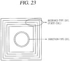
- an employment of a structure in which a coil compliant with an induction method (or an induction-type coil) is surrounded by a coil compliant with a resonance method (or resonance-type coil) may result in implement of an induction/resonance-interoperable coil.
- the interoperable coil in the structure can be normally driven.
- the induction/resonance-interoperable coil and a communication method thereof disclosed herein may provide a transient technology for improving the conventional induction method which has been already commercialized into the resonance method.
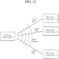
- the induction/resonance-interoperable communication method may facilitate for communication between one transmitter and a plurality of receivers.
- a communication protocol-compatible wireless charging system can be implemented in a manner that a receiver transmits a list of communication protocols supportable thereby to a transmitter.
- the technologies disclosed herein may be applicable to wireless power transfer (or wireless power transmission). However, the technologies disclosed herein are not limited to this, and may be also applicable to all kinds of power transmission systems and methods, and wireless charging circuits, in addition to the methods and apparatuses using power transmitted in a wireless manner.
- technological terms used herein are merely used to describe a specific embodiment, but not to limit the present invention. Also, unless particularly defined otherwise, technological terms used herein should be construed as a meaning that is generally understood by those having ordinary skill in the art to which the invention pertains, and should not be construed too broadly or too narrowly. Furthermore, if technological terms used herein are wrong terms, then they should be replaced by technological terms that are properly understood by those skilled in the art. In addition, general terms used in this invention should be construed based on the definition of dictionary, or the context, and should not be construed too broadly or too narrowly.
- first, second, etc. can be used to describe various elements, but the elements should not be limited by those terms. The terms are used merely for the purpose to distinguish an element from the other element. For example, a first element may be named to a second element, and similarly, a second element may be named to a first element without departing from the scope of right of the invention.
- the transmitter and the receiver indicate the same as a transmitting unit (device) and a receiving unit (device), respectively.
- a transmitting unit device
- a receiving unit device
- FIG. 1 is an exemplary view conceptually illustrating a wireless power transmitter and a wireless power receiver according to the embodiments of the present invention.
- a wireless power transmitter 100 may be a power transfer apparatus configured to transfer power required for a wireless power receiver 200 in a wireless manner.
- the wireless power transmitter 100 may be a wireless charging apparatus configured to charge a battery of the wireless power receiver 200 by transferring power in a wireless manner.
- the wireless power transmitter 100 may be implemented with various forms of apparatuses transferring power to the wireless power receiver 200 requiring power in a contactless state.
- the wireless power receiver 200 is a device that is operable by receiving power from the wireless power transmitter 100 in a wireless manner. Furthermore, the wireless power receiver 200 may charge a battery using the received wireless power.
- the wireless power receiver for receiving power in a wireless manner as described herein should be construed broadly to include a portable phone, a cellular phone, a smart phone, a personal digital assistant (PDA), a portable multimedia player (PMP), a tablet, a multimedia device, or the like, in addition to an input/output device such as a keyboard, a mouse, an audio-visual auxiliary device, and the like.
- PDA personal digital assistant
- PMP portable multimedia player
- a tablet a multimedia device, or the like
- an input/output device such as a keyboard, a mouse, an audio-visual auxiliary device, and the like.
- the wireless power receiver 200 may be a mobile communication terminal (for example, a portable phone, a cellular phone, a tablet and the like) or a multimedia device.
- the wireless power transmitter 100 may transfer power in a wireless manner without mutual contact to the wireless power receiver 200 using one or more wireless power transfer methods.
- the wireless power transmitter 100 may transfer power using at least one of an inductive coupling method based on magnetic induction phenomenon by the wireless power signal and a magnetic resonance coupling method based on electromagnetic resonance phenomenon by a wireless power signal at a specific frequency.
- Wireless power transfer in the inductive coupling method is a technology transferring power in a wireless manner using a primary coil and a secondary coil, and refers to the transmission of power by inducing a current from a coil to another coil through a changing magnetic field by a magnetic induction phenomenon.
- Wireless power transfer in the inductive coupling method refers to a technology in which the wireless power receiver 200 generates resonance by a wireless power signal transmitted from the wireless power transmitter 100 to transfer power from the wireless power transmitter 100 to the wireless power receiver 200 by the resonance phenomenon.
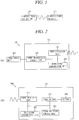
- FIGS. 2A and 2B are exemplary block diagrams illustrating the configuration of a wireless power transmitter 100 and a wireless power receiver 200 that can be employed in the embodiments disclosed herein.
- the wireless power transmitter 100 may include a power transmission unit 110.
- the power transmission unit 110 may include a power conversion unit 111 and a power transmission control unit 112.
- the power conversion unit 111 transfers power supplied from a transmission side power supply unit 190 to the wireless power receiver 200 by converting it into a wireless power signal.
- the wireless power signal transferred by the power conversion unit 111 is generated in the form of a magnetic field or electro-magnetic field having an oscillation characteristic.
- the power conversion unit 111 may be configured to include a coil for generating the wireless power signal.
- the power conversion unit 111 may include a constituent element for generating a different type of wireless power signal according to each power transfer method.
- the power conversion unit 111 may include a primary coil for forming a changing magnetic field to induce a current to a secondary coil of the wireless power receiver 200.
- the power conversion unit 111 may include a coil (or antenna) for forming a magnetic field having a specific resonant frequency to generate a resonant frequency in the wireless power receiver 200 according to the resonance coupling method.
- the power conversion unit 111 may transfer power using at least one of the foregoing inductive coupling method and the resonance coupling method.
- the power conversion unit 111 may further include a circuit for controlling the characteristics of a used frequency, an applied voltage, an applied current or the like to form the wireless power signal.
- the power transmission control unit 112 controls each of the constituent elements included in the power transmission unit 110.
- the power transmission control unit 112 may be implemented to be integrated into another control unit (not shown) for controlling the wireless power transmitter 100.
- a region which the wireless power signal can be approached may be divided into two types.
- an active area denotes a region through which a wireless power signal transferring power to the wireless power receiver 200 is passed.
- a semi-active area denotes an interest region in which the wireless power transmitter 100 can detect the existence of the wireless power receiver 200.
- the power transmission control unit 112 may detect whether the wireless power receiver 200 is placed in the active area or detection area or removed from the area. Specifically, the power transmission control unit 112 may detect whether or not the wireless power receiver 200 is placed in the active area or detection area using a wireless power signal formed from the power conversion unit 111 or a sensor separately provided therein.
- the power transmission control unit 112 may detect the presence of the wireless power receiver 200 by monitoring whether or not the characteristic of power for forming the wireless power signal is changed by the wireless power signal, which is affected by the wireless power receiver 200 existing in the detection area.
- the active area and detection area may vary according to the wireless power transfer method such as an inductive coupling method, a resonance coupling method, and the like.
- the power transmission control unit 112 may perform the process of identifying the wireless power receiver 200 or determine whether to start wireless power transfer according to a result of detecting the existence of the wireless power receiver 200.
- the power transmission control unit 112 may determine at least one characteristic of a frequency, a voltage, and a current of the power conversion unit 111 for forming the wireless power signal.
- the determination of the characteristic may be carried out by a condition at the side of the wireless power transmitter 100 or a condition at the side of the wireless power receiver 200.
- the power transmission control unit 112 may receive a power control message from the wireless power receiver 200.
- the power transmission control unit 112 may determine at least one characteristic of a frequency, a voltage and a current of the power conversion unit 111 based on the received power control message, and additionally perform other control operations based on the power control message.
- the power transmission control unit 112 may determine at least one characteristic of a frequency, a voltage and a current used to form the wireless power signal according to the power control message including at least one of rectified power amount information, charging state information and identification information in the wireless power receiver 200.
- the wireless power transmitter 100 may perform a typical control operation associated with wireless power transfer based on the power control message.
- the wireless power transmitter 100 may receive information associated with the wireless power receiver 200 to be auditorily or visually outputted through the power control message, or receive information required for authentication between devices.
- the power transmission control unit 112 may receive the power control message through the wireless power signal. In other exemplary embodiment, the power transmission control unit 112 may receive the power control message through a method for receiving user data.
- the wireless power transmitter 100 may further include a modulation/demodulation unit 113 electrically connected to the power conversion unit 111.
- the modulation/demodulation unit 113 may demodulate a wireless power signal that has been modulated by the wireless power receiver 200 and use it to receive the power control message.
- the power transmission control unit 112 may acquire a power control message by receiving user data including the power control message by a communication means (not shown) included in the wireless power transmitter 100.
- the power transmission control unit 112 may transmit data to the wireless power receiver 200.
- the data transmitted by the power transmission control unit 112 may be transmitted to request the wireless power receiver 200 to send the power control message.
- the wireless power receiver 200 may include a power supply unit 290.
- the power supply unit 290 supplies power required for the operation of the wireless power receiver 200.
- the power supply unit 290 may include a power receiving unit 291 and a power reception control unit 292.
- the power receiving unit 291 receives power transferred from the wireless power transmitter 100 in a wireless manner.
- the power receiving unit 291 may include constituent elements required to receive the wireless power signal according to a wireless power transfer method. Furthermore, the power receiving unit 291 may receive power according to at least one wireless power transfer method, and in this case, the power receiving unit 291 may include constituent elements required for each method.
- the power receiving unit 291 may include a coil for receiving a wireless power signal transferred in the form of a magnetic field or electromagnetic field having a vibration characteristic.
- the power receiving unit 291 may include a secondary coil to which a current is induced by a changing magnetic field.
- the power receiving unit 291 as a constituent element according to the resonance coupling method, may include a coil and a resonant circuit in which resonance phenomenon is generated by a magnetic field having a specific resonant frequency.
- the power receiving unit 291 when the power receiving unit 291 receives power according to at least one wireless power transfer method, the power receiving unit 291 may be implemented to receive power by using a coil, or implemented to receive power by using a coil formed differently according to each power transfer method.
- the power receiving unit 291 may further include a rectifier and a regulator to convert the wireless power signal into a direct current. Furthermore, the power receiving unit 291 may further include a circuit for protecting an overvoltage or overcurrent from being generated by the received power signal.
- the power reception control unit 292 may control each constituent element included in the power supply unit 290.
- the power reception control unit 292 may transfer a power control message to the wireless power transmitter 100.
- the power control message may instruct the wireless power transmitter 100 to initiate or terminate a transfer of the wireless power signal.
- the power control message may instruct the wireless power transmitter 100 to control a characteristic of the wireless power signal.
- the power reception control unit 292 may transmit the power control message through at least one of the wireless power signal and user data.
- the wireless power receiver 200 may further include a modulation/demodulation unit 293 electrically connected to the power receiving unit 291.
- the modulation/demodulation unit 293 similarly to the case of the wireless power transmitter 100, may be used to transmit the power control message through the wireless power signal.
- the power communications modulation/demodulation unit 293 may be used as a means for controlling a current and/or voltage flowing through the power conversion unit 111 of the wireless power transmitter 100.
- a method for allowing the power communications modulation/demodulation unit 113 or 293 at the side of the wireless power transmitter 100 and at the side of the wireless power receiver 200, respectively, to be used to transmit and receive a power control message through a wireless power signal will be described.
- a wireless power signal formed by the power conversion unit 111 is received by the power receiving unit 291.
- the power reception control unit 292 controls the power communications modulation/demodulation unit 293 at the side of the wireless power receiver 200 to modulate the wireless power signal.
- the power reception control unit 292 may perform a modulation process such that a power amount received from the wireless power signal is varied by changing a reactance of the power communications modulation/demodulation unit 293 connected to the power receiving unit 291.
- the change of a power amount received from the wireless power signal results in the change of a current and/or voltage of the power conversion unit 111 for forming the wireless power signal.
- the modulation/demodulation unit 113 at the side of the wireless power transmitter 100 may detect a change of the current and/or voltage to perform a demodulation process.
- the power reception control unit 292 may generate a packet including a power control message intended to be transferred to the wireless power transmitter 100 and modulate the wireless power signal to allow the packet to be included therein, and the power transmission control unit 112 may decode the packet based on a result of performing the demodulation process of the power communications modulation/demodulation unit 113 to acquire the power control message included in the packet.
- the power reception control unit 292 may transmit a power control message to the wireless power transmitter 100 by transmitting user data including the power control message by a communication means (not shown) included in the wireless power receiver 200.
- the power reception control unit 292 may receive data to the wireless power transmitter 100.
- the data transmitted by the wireless power transmitter 100 may be transmitted to request the wireless power receiver 200 to send the power control message.
- the power supply unit 290 may further include a charger 298 and a battery 299.
- the wireless power receiver 200 receiving power for operation from the power supply unit 290 may be operated by power transferred from the wireless power transmitter 100, or operated by charging the battery 299 using the transferred power and then receiving the charged power.
- the power reception control unit 292 may control the charger 298 to perform charging using the transferred power.
- FIG. 3 is a view illustrating a concept in which power is transferred from a wireless power transmitter to an electronic device in a wireless manner according to an inductive coupling method.
- the power of the wireless power transmitter 100 is transferred in an inductive coupling method, if the strength of a current flowing through a primary coil within the power transmission unit 110 is changed, then a magnetic field passing through the primary coil will be changed by the current. The changed magnetic field generates an induced electromotive force at a secondary coil in the wireless power receiver 200.
- the power conversion unit 111 of the wireless power transmitter 100 may include a transmitting (Tx) coil 1111 a being operated as a primary coil in magnetic induction.
- the power receiving unit 291 of the wireless power receiver 200 may include a receiving (Rx) coil 2911a being operated as a secondary coil in magnetic induction.
- the wireless power transmitter 100 and wireless power receiver 200 are disposed in such a manner that the transmitting coil 1111a at the side of the wireless power transmitter 100 and the receiving coil at the side of the wireless power receiver 200 are located adjacent to each other. Then, if the power transmission control unit 112 controls a current of the transmitting coil (Tx coil) 1111a to be changed, then the power receiving unit 291 controls power to be supplied to the wireless power receiver 200 using an electromotive force induced to the receiving coil (Rx coil) 2911a.
- the efficiency of wireless power transfer by the inductive coupling method may be little affected by a frequency characteristic, but affected by an alignment and distance between the wireless power transmitter 100 and the wireless power receiver 200 including each coil.
- the wireless power transmitter 100 may be configured to include an interface surface (not shown) in the form of a flat surface.
- One or more electronic devices may be placed at an upper portion of the interface surface, and the transmitting coil 1111a may be mounted at a lower portion of the interface surface.
- a vertical spacing is formed in a small-scale between the transmitting coil 1111a mounted at a lower portion of the interface surface and the receiving coil 2911a of the wireless power receiver 200 placed at an upper portion of the interface surface, and thus a distance between the coils becomes sufficiently small to efficiently implement contactless power transfer by the inductive coupling method.
- an alignment indicator (not shown) indicating a location where the wireless power receiver 200 is to be placed at an upper portion of the interface surface.
- the alignment indicator indicates a location of the wireless power receiver 200 where an alignment between the transmitting coil 1111a mounted at a lower portion of the interface surface and the receiving coil 2911a can be suitably implemented.
- the alignment indicator may alternatively be simple marks, or may be formed in the form of a protrusion structure for guiding the location of the wireless power receiver 200. Otherwise, the alignment indicator may be formed in the form of a magnetic body such as a magnet mounted at a lower portion of the interface surface, thereby guiding the coils to be suitably arranged by mutual magnetism to a magnetic body having an opposite polarity mounted within the wireless power receiver 200.
- the wireless power transmitter 100 may be formed to include one or more transmitting coils.
- the wireless power transmitter 100 may selectively use some of coils suitably arranged with the receiving coil 2911a of the wireless power receiver 200 among the one or more transmitting coils to enhance the power transmission efficiency.
- the wireless power transmitter 100 including the one or more transmitting coils will be described later with reference to FIG. 5 .
- FIG. 4 is a block diagram illustrating part of the wireless power transmitter 100 and wireless power receiver 200 in a magnetic induction method that can be employed in the embodiments disclosed herein.
- a configuration of the power transmission unit 110 included in the wireless power transmitter 100 will be described with reference to FIG. 4A
- a configuration of the power supply unit 290 included in the wireless power receiver 200 will be described with reference to FIG. 4B .
- the power conversion unit 111 of the wireless power transmitter 100 may include a transmitting (Tx) coil 1111a and an inverter 1112.
- the transmitting coil 1111a may form a magnetic field corresponding to the wireless power signal according to a change of current as described above.
- the transmitting coil 1111a may alternatively be implemented with a planar spiral type or cylindrical solenoid type.
- the inverter 1112 transforms a DC input obtained from the power supply unit 190 into an AC waveform.
- the AC current transformed by the inverter 1112 drives a resonant circuit including the transmitting coil 1111 a and a capacitor (not shown) to form a magnetic field in the transmitting coil 1111a.
- the power conversion unit 111 may further include a positioning unit 1114.
- the positioning unit 1114 may move or rotate the transmitting coil 1111a to enhance the effectiveness of contactless power transfer using the inductive coupling method. As described above, it is because an alignment and distance between the wireless power transmitter 100 and the wireless power receiver 200 including a primary coil and a secondary coil may affect power transfer using the inductive coupling method. In particular, the positioning unit 1114 may be used when the wireless power receiver 200 does not exist within an active area of the wireless power transmitter 100.
- the positioning unit 1114 may include a drive unit (not shown) for moving the transmitting coil 1111a such that a center-to-center distance of the transmitting coil 1111a of the wireless power transmitter 100 and the receiving coil 2911a of the wireless power receiver 200 is within a predetermined range, or rotating the transmitting coil 1111a such that the centers of the transmitting coil 1111a and the receiving coil 2911a are overlapped with each other.
- a drive unit not shown
- the wireless power transmitter 100 may further include a detection unit (not shown) made of a sensor for detecting the location of the wireless power receiver 200, and the power transmission control unit 112 may control the positioning unit 1114 based on the location information of the wireless power receiver 200 received from the location detection sensor.
- a detection unit made of a sensor for detecting the location of the wireless power receiver 200
- the power transmission control unit 112 may control the positioning unit 1114 based on the location information of the wireless power receiver 200 received from the location detection sensor.
- the power transmission control unit 112 may receive control information on an alignment or distance to the wireless power receiver 200 through the power communications modulation/demodulation unit 113, and control the positioning unit 1114 based on the received control information on the alignment or distance.
- the positioning unit 1114 may determine which one of the plurality of transmitting coils is to be used for power transmission.
- the configuration of the wireless power transmitter 100 including the plurality of transmitting coils will be described later with reference to FIG. 5 .
- the power conversion unit 111 may further include a power sensing unit 1115.
- the power sensing unit 1115 at the side of the wireless power transmitter 100 monitors a current or voltage flowing into the transmitting coil 1111a.
- the power sensing unit 1115 is provided to check whether or not the wireless power transmitter 100 is normally operated, and thus the power sensing unit 1115 may detect a voltage or current of the power supplied from the outside, and check whether the detected voltage or current exceeds a threshold value.
- the power sensing unit 1115 although not shown, may include a resistor for detecting a voltage or current of the power supplied from the outside and a comparator for comparing a voltage value or current value of the detected power with a threshold value to output the comparison result. Based on the check result of the power sensing unit 1115, the power transmission control unit 112 may control a switching unit (not shown) to cut off power applied to the transmitting coil 1111a.
- the power supply unit 290 of the wireless power receiver 200 may include a receiving (Rx) coil 2911a and a rectifier 2913.
- a current is induced into the receiving coil 2911a by a change of the magnetic field formed in the transmitting coil 1111a.
- the implementation type of the receiving coil 2911a may be a planar spiral type or cylindrical solenoid type similarly to the transmitting coil 1111a.
- series and parallel capacitors may be configured to be connected to the receiving coil 2911a to enhance the effectiveness of wireless power reception or perform resonant detection.
- the receiving coil 2911a may be in the form of a single coil or a plurality of coils.
- the rectifier 2913 performs a full-wave rectification to a current to convert alternating current into direct current.
- the rectifier 2913 may be implemented with a full-bridge rectifier made of four diodes or a circuit using active components.
- the rectifier 2913 may further include a regulator for converting a rectified current into a more flat and stable direct current. Furthermore, the output power of the rectifier 2913 is supplied to each constituent element of the power supply unit 290. Furthermore, the rectifier 2913 may further include a DC-DC converter for converting output DC power into a suitable voltage to adjust it to the power required for each constituent element (for instance, a circuit such as a charger 298).
- the power communications modulation/demodulation unit 293 may be connected to the power receiving unit 291, and may be configured with a resistive element in which resistance varies with respect to direct current, and may be configured with a capacitive element in which reactance varies with respect to alternating current.
- the power reception control unit 292 may change the resistance or reactance of the power communications modulation/demodulation unit 293 to modulate a wireless power signal received to the power receiving unit 291.
- the power supply unit 290 may further include a power sensing unit 2914.
- the power sensing unit 2914 at the side of the wireless power receiver 200 monitors a voltage and/or current of the power rectified by the rectifier 2913, and if the voltage and/or current of the rectified power exceeds a threshold value as a result of monitoring, then the power reception control unit 292 transmits a power control message to the wireless power transmitter 100 to transfer suitable power.
- Wireless power transmitter configured to include one or more transmitting coils
- FIG. 5 is a block diagram illustrating a wireless power transmitter configured to have one or more transmission coils receiving power according to an inductive coupling method that can be employed in the embodiments disclosed herein.
- the power conversion unit 111 of the wireless power transmitter 100 may include one or more transmitting coils 1111a-1 to 1111a-n.
- the one or more transmitting coils 1111a-1 to 1111a-n may be an array of partly overlapping primary coils.
- An active area may be determined by some of the one or more transmitting coils.
- the one or more transmitting coils 1111a-1 to 1111a-n may be mounted at a lower portion of the interface surface. Furthermore, the power conversion unit 111 may further include a multiplexer 1113 for establishing and releasing the connection of some of the one or more transmitting coils 1111a-1 to 1111a-n.
- the power transmission control unit 112 may take the detected location of the wireless power receiver 200 into consideration to control the multiplexer 1113, thereby allowing coils that can be placed in an inductive coupling relation to the receiving coil 2911a of the wireless power receiver 200 among the one or more transmitting coils 1111 a-1 to 1111 a-n to be connected to one another.
- the power transmission control unit 112 may acquire the location information of the wireless power receiver 200.
- the power transmission control unit 112 may acquire the location of the wireless power receiver 200 on the interface surface by the location detection unit (not shown) provided in the wireless power transmitter 100.
- the power transmission control unit 112 may alternatively receive a power control message indicating a strength of the wireless power signal from an object on the interface surface or a power control message indicating the identification information of the object using the one or more transmitting coils 1111a-1 to 1111a-n, respectively, and determines whether it is located adjacent to which one of the one or more transmitting coils based on the received result, thereby acquiring the location information of the wireless power receiver 200.
- the active area as part of the interface surface may denote a portion through which a magnetic field with a high efficiency can pass when the wireless power transmitter 100 transfers power to the wireless power receiver 200 in a wireless manner.
- a single transmitting coil or a combination of one or more transmitting coils forming a magnetic field passing through the active area may be designated as a primary cell.
- the power transmission control unit 112 may determine an active area based on the detected location of the wireless power receiver 200, and establish the connection of a primary cell corresponding to the active area to control the multiplexer 1113, thereby allowing the receiving coil 2911a of the wireless power receiver 200 and the coils belonging to the primary cell to be placed in an inductive coupling relation.
- the power conversion unit 111 may further include an impedance matching unit (not shown) for controlling an impedance to form a resonant circuit with the coils connected thereto.
- an impedance matching unit (not shown) for controlling an impedance to form a resonant circuit with the coils connected thereto.
- FIGS. 6 through 8 a method for allowing a wireless power transmitter to transfer power according to a resonance coupling method will be disclosed with reference to FIGS. 6 through 8 .
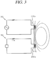
- FIG. 6 is a view illustrating a concept in which power is transferred to an electronic device from a wireless power transmitter in a wireless manner according to a resonance coupling method.
- Resonance refers to a phenomenon in which amplitude of vibration is remarkably increased when periodically receiving an external force having the same frequency as the natural frequency of a vibration system.
- Resonance is a phenomenon occurring at all kinds of vibrations such as mechanical vibration, electric vibration, and the like.
- the vibration becomes strong, thus increasing the width.
- a resonant circuit can be made by using an inductor and a capacitor.
- a magnetic field having a specific vibration frequency is formed by alternating current power in the power transmission unit 110. If a resonance phenomenon occurs in the wireless power receiver 200 by the formed magnetic field, then power is generated by the resonance phenomenon in the wireless power receiver 200.
- the resonant frequency (f) is determined by an inductance (L) and a capacitance (C) in a circuit.
- the inductance can be determined by a number of turns of the coil, and the like, and the capacitance can be determined by a gap between the coils, an area, and the like.
- a capacitive resonant circuit may be configured to be connected thereto to determine the resonant frequency.
- the power conversion unit 111 of the wireless power transmitter 100 may include a transmitting (Tx) coil 1111b in which a magnetic field is formed and a resonant circuit 1116 connected to the transmitting coil 1111b to determine a specific vibration frequency.
- the resonant circuit 1116 may be implemented by using a capacitive circuit (capacitors), and the specific vibration frequency may be determined based on an inductance of the transmitting coil 1111b and a capacitance of the resonant circuit 1116.
- the configuration of a circuit element of the resonant circuit 1116 may be implemented in various forms such that the power conversion unit 111 forms a magnetic field, and is not limited to a form of being connected in parallel to the transmitting coil 1111 b as illustrated in FIG. 6 .
- the power receiving unit 291 of the wireless power receiver 200 may include a resonant circuit 2912 and a receiving (Rx) coil 2911b to generate a resonance phenomenon by a magnetic field formed in the wireless power transmitter 100.
- the resonant circuit 2912 may be also implemented by using a capacitive circuit, and the resonant circuit 2912 is configured such that a resonant frequency determined based on an inductance of the receiving coil 2911b and a capacitance of the resonant circuit 2912 has the same frequency as a resonant frequency of the formed magnetic field.
- the configuration of a circuit element of the resonant circuit 2912 may be implemented in various forms such that the power receiving unit 291 generates resonance by a magnetic field, and is not limited to a form of being connected in series to the receiving coil 2911b as illustrated in FIG. 6 .
- the specific vibration frequency in the wireless power transmitter 100 may have LTX, CTX, and may be acquired by using the Equation 1.
- the wireless power receiver 200 generates resonance when a result of substituting the LRX and CRX of the wireless power receiver 200 to the Equation 1 is same as the specific vibration frequency.
- an efficiency of contactless power transfer by the resonance coupling method is greatly affected by a frequency characteristic, whereas the effect of an alignment and distance between the wireless power transmitter 100 and the wireless power receiver 200 including each coil is relatively smaller than the inductive coupling method.
- FIG. 7 is a block diagram illustrating part of the wireless power transmitter 100 and wireless power receiver 200 in a resonance method that can be employed in the embodiments disclosed herein.
- a configuration of the power transmission unit 110 included in the wireless power transmitter 100 will be described with reference to FIG. 7A .
- the power conversion unit 111 of the wireless power transmitter 100 may include a transmitting (Tx) coil 1111b, an inverter 1112, and a resonant circuit 1116.
- the inverter 1112 may be configured to be connected to the transmitting coil 1111b and the resonant circuit 1116.
- the transmitting coil 1111b may be mounted separately from the transmitting coil 1111a for transferring power according to the inductive coupling method, but may transfer power in the inductive coupling method and resonance coupling method using one single coil.
- the transmitting coil 1111b forms a magnetic field for transferring power.
- the transmitting coil 1111b and the resonant circuit 1116 generate resonance when alternating current power is applied thereto, and at this time, a vibration frequency may be determined based on an inductance of the transmitting coil 1111b and a capacitance of the resonant circuit 1116.
- the inverter 1112 transforms a DC input obtained from the power supply unit 190 into an AC waveform, and the transformed AC current is applied to the transmitting coil 1111b and the resonant circuit 1116.
- the power conversion unit 111 may further include a frequency adjustment unit 1117 for changing a resonant frequency of the power conversion unit 111.
- the resonant frequency of the power conversion unit 111 is determined based on an inductance and/or capacitance within a circuit constituting the power conversion unit 111 by Equation 1, and thus the power transmission control unit 112 may determine the resonant frequency of the power conversion unit 111 by controlling the frequency adjustment unit 1117 to change the inductance and/or capacitance.
- the frequency adjustment unit 1117 may be configured to include a motor for adjusting a distance between capacitors included in the resonant circuit 1116 to change a capacitance, or include a motor for adjusting a number of turns or diameter of the transmitting coil 1111b to change an inductance, or include active elements for determining the capacitance and/or inductance
- the power conversion unit 111 may further include a power sensing unit 1115.
- the operation of the power sensing unit 1115 is the same as the foregoing description.
- the power supply unit 290 may include the receiving (Rx) coil 2911b and resonant circuit 2912.
- the power receiving unit 291 of the power supply unit 290 may further include a rectifier 2913 for converting an AC current generated by resonance phenomenon into DC.
- the rectifier 2913 may be configured similarly to the foregoing description.
- the power receiving unit 291 may further include a power sensing unit 2914 for monitoring a voltage and/or current of the rectified power.
- the power sensing unit 2914 may be configured similarly to the foregoing description.
- Wireless power transmitter configured to include one or more transmitting coils
- FIG. 8 is a block diagram illustrating a wireless power transmitter configured to have one or more transmission coils receiving power according to a resonance coupling method that can be employed in the embodiments disclosed herein.
- the power conversion unit 111 of the wireless power transmitter 100 may include one or more transmitting coils 1111b-1 to 1111b-n and resonant circuits (1116-1 to 1116-n) connected to each transmitting coils. Furthermore, the power conversion unit 111 may further include a multiplexer 1113 for establishing and releasing the connection of some of the one or more transmitting coils 1111b-1 to 1111b-n.
- the one or more transmitting coils 1111b-1 to 1111b-n may be configured to have the same vibration frequency, or some of them may be configured to have different vibration frequencies. It is determined by an inductance and/or capacitance of the resonant circuits (1116-1 to 1116-n) connected to the one or more transmitting coils 1111b-1 to 1111b-n, respectively.
- the frequency adjustment unit 1117 may be configured to change an inductance and/or capacitance of the resonant circuits (1116-1 to 1116-n) connected to the one or more transmitting coils 1111 b-1 to 1111b-n, respectively.
- FIG. 9 a view illustrating the concept of transmitting and receiving a packet between a wireless power transmitter and a wireless power receiver through the modulation and demodulation of a wireless power signal in transferring power in a wireless manner disclosed herein.
- the power conversion unit 111 included in the wireless power transmitter 100 may generate a wireless power signal.
- the wireless power signal may be generated through the transmitting coil 1111 included in the power conversion unit 111.
- the wireless power signal 10a generated by the power conversion unit 111 may arrive at the wireless power receiver 200 so as to be received through the power receiving unit 291 of the wireless power receiver 200.
- the generated wireless power signal may be received through the receiving coil 2911 included in the power receiving unit 291.
- the power reception control unit 292 may control the modulation/demodulation unit 293 connected to the power receiving unit 291 to modulate the wireless power signal while the wireless power receiver 200 receives the wireless power signal.
- the wireless power signal may form a closed-loop within a magnetic field or an electro-magnetic field. This may allow the wireless power transmitter 100 to sense a modulated wireless power signal 10b.
- the modulation/demodulation unit 113 may demodulate the sensed wireless power signal and decode the packet from the demodulated wireless power signal.
- the modulation method employed for the communication between the wireless power transmitter 100 and the wireless power receiver 200 may be an amplitude modulation.
- the amplitude modulation is a backscatter modulation may be a backscatter modulation method in which the power communications modulation/demodulation unit 293 at the side of the wireless power receiver 200 changes an amplitude of the wireless power signal 10a formed by the power conversion unit 111 and the power reception control unit 292 at the side of the wireless power transmitter 100 detects an amplitude of the modulated wireless power signal 10b.
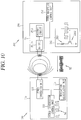
- FIG. 10 is a view illustrating a configuration of transmitting or receiving a power control message in transferring power in a wireless manner disclosed herein
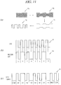
- FIG. 11 is a view illustrating forms of signals upon modulation and demodulation executed in the wireless power transfer disclosed herein.
- the wireless power signal received through the power receiving unit 291 of the wireless power receiver 200 may be a non-modulated wireless power signal 51.
- the wireless power receiver 200 and the wireless power transmitter 100 may establish a resonance coupling according to a resonant frequency, which is set by the resonant circuit 2912 within the power receiving unit 291, and the wireless power signal 51 may be received through the receiving coil 2911b.
- the power reception control unit 292 may modulate the wireless power signal 51 received through the power receiving unit 291 by changing a load impedance within the modulation/demodulation unit 293.
- the modulation/demodulation unit 293 may include a passive element 2931 and an active element 2932 for modulating the wireless power signal 51.
- the modulation/demodulation unit 293 may modulate the wireless power signal 51 to include a packet, which is desired to be transmitted to the wireless power transmitter 100. Here, the packet may be input into the active element 2932 within the modulation/demodulation unit 293.
- the power transmission control unit 112 of the wireless power transmitter 100 may demodulate a modulated wireless power signal 52 through an envelop detection, and decode the detected signal 53 into digital data 54.
- the demodulation may detect a current or voltage flowing into the power conversion unit 111 to be classified into two phases, a HI phase and a LO phase, and acquire a packet to be transmitted by the wireless power receiver 200 based on digital data classified according to the phases.
- the power transmission control unit 112 detects an encoded bit using a clock signal (CLK) from an envelope detected signal.
- CLK clock signal
- the detected encoded bit is encoded according to a bit encoding method used in the modulation process at the side of the wireless power receiver 200.
- the bit encoding method may correspond to any one of non-return to zero (NRZ) and bi-phase encoding.
- the detected bit may be a differential bi-phase (DBP) encoded bit.
- DBP differential bi-phase
- the power reception control unit 292 at the side of the wireless power receiver 200 is allowed to have two state transitions to encode data bit 1, and to have one state transition to encode data bit 0.
- data bit 1 may be encoded in such a manner that a transition between the HI phase and LO phase is generated at a rising edge and falling edge of the clock signal
- data bit 0 may be encoded in such a manner that a transition between the HI phase and LO phase is generated at a rising edge of the clock signal.
- the power transmission control unit 112 may acquire data in a byte unit using a byte format constituting a packet from a bit string detected according to the bit encoding method.
- the detected bit string may be transferred by using an 11-bit asynchronous serial format as illustrated in FIG. 12C .
- the detected bit may include a start bit indicating the beginning of a byte and a stop bit indicating the end of a byte, and also include data bits (b0 to b7) between the start bit and the stop bit. Furthermore, it may further include a parity bit for checking an error of data.
- the data in a byte unit constitutes a packet including a power control message.
- FIG. 9 has illustrated that the wireless power receiver 200 transmits a packet using a carrier signal 10a formed by the wireless power transmitter 100.
- the wireless power transmitter 100 may also transmit data to the wireless power receiver 200 by a similar method.
- the power transmission control unit 112 may control the modulation/demodulation unit 113 to modulate data, which is to be transmitted to the wireless power receiver 200, such that the data can be included in the carrier signal 10a.
- the power reception control unit 292 of the wireless power receiver 200 may control the modulation/demodulation unit 293 to execute demodulation so as to acquire data from the modulated carrier signal 10a.
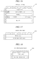
- FIG. 12 is a view illustrating a packet including a power control message used in a contactless (wireless) power transfer method according to the embodiments disclosed herein.
- the wireless power transmitter 100 and the wireless power receiver 200 may transmit and receive data desired to transmit in a form of a command packet (command_packet) 510.
- the command packet 510 may include a header 511 and a message 512.
- the header 511 may include a field indicating a type of data included in the message 512. Size and type of the message may be decided based on a value of the field which indicates the type of data.
- the header 511 may include an address field for identifying a transmitter (originator) of the packet.
- the address field may indicate an identifier of the wireless power receiver 200 or an identifier of a group to which the wireless power receiver 200 belongs.
- the wireless power receiver 200 may generate the packet 510 such that the address field can indicate identification information related to the receiver 200 itself.
- the message 512 may include data that the originator of the packet 510 desires to transmit.
- the data included in the message 512 may be a report, a request or a response for the other party.
- the command packet 510 may be configured as illustrated in (b) of FIG. 12 .
- the header 511 included in the command packet 510 may be represented with a predetermined size.
- the header 511 may have a 2-byte size.
- the header 511 may include a reception address field.
- the reception address field may have a 6-bit size.
- the header 511 may include an operation command field (OCF) or an operation group field (OGF).
- OGF is a value given for each group of commands for the wireless power receiver 200
- OCF is a value given for each command existing in each group in which the wireless power receiver 200 is included.
- the message 512 may be divided into a length field 5121 of a parameter and a value field 5122 of the parameter. That is, the originator of the packet 510 may generate the message by a length-value pair (5121a-5122a, etc.) of at least one parameter, which is required to represent data desired to transmit.
- the wireless power transmitter 100 and the wireless power receiver 200 may transmit and receive the data in a form of a packet which further has a preamble 520 and a checksum 530 added to the command packet 510.
- the preamble 520 may be used to perform synchronization with data received by the wireless power transmitter 100 and detect the start bit of the header 520.
- the preamble 520 may be configured to repeat the same bit. For instance, the preamble 520 may be configured such that data bit 1 according to the DBP encoding is repeated eleven to twenty five times.
- the checksum 530 may be used to detect an error that can be occurred in the command packet 510 while transmitting a power control message.
- FIG. 13 illustrates the operation phases of the wireless power transmitter 100 and the wireless power receiver 200 according to the embodiments disclosed herein. Furthermore, FIGS. 14 to 18 illustrate the structures of packets including a power control message between the wireless power transmitter 100 and the wireless power receiver 200.
- the operation phases of the wireless power transmitter 100 and the wireless power receiver 200 for wireless power transfer may be divided into a selection phase (state) 610, a ping phase 620, an identification and configuration phase 630, and a power transfer phase 640.
- the wireless power transmitter 100 detects whether or not objects exist within a range that the wireless power transmitter 100 can transmit power in a wireless manner in the selection phase 610, and the wireless power transmitter 100 sends a detection signal to the detected object and the wireless power receiver 200 sends a response to the detection signal in the ping phase 620.
- the wireless power transmitter 100 identifies the wireless power receiver 200 selected through the previous phases and acquires configuration information for power transmission in the identification and configuration phase 630.
- the wireless power transmitter 100 transmits power to the wireless power receiver 200 while controlling power transmitted in response to a control message received from the wireless power receiver 200 in the power transfer phase 640.
- the wireless power transmitter 100 in the selection phase 610 performs a detection process to select the wireless power receiver 200 existing within a detection area.
- the detection area refers to a region in which an object within the relevant area can affect on the characteristic of the power of the power conversion unit 111.
- the detection process for selecting the wireless power receiver 200 in the selection phase 610 is a process of detecting a change of the power amount for forming a wireless power signal in the power conversion unit at the side of the wireless power transmitter 100 to check whether any object exists within a predetermined range, instead of the scheme of receiving a response from the wireless power receiver 200 using a power control message.
- the detection process in the selection phase 610 may be referred to as an analog ping process in the aspect of detecting an object using a wireless power signal without using a packet in a digital format in the ping phase 620 which will be described later.
- the wireless power transmitter 100 in the selection phase 610 can detect that an object comes in or out within the detection area. Furthermore, the wireless power transmitter 100 can distinguish the wireless power receiver 200 capable of transferring power in a wireless manner from other objects (for example, a key, a coin, etc.) among objects located within the detection area.
- a distance that can transmit power in a wireless manner may be different according to the inductive coupling method and resonance coupling method, and thus the detection area for detecting an object in the selection phase 610 may be different from one another.
- the wireless power transmitter 100 in the selection phase 610 can monitor an interface surface (not shown) to detect the alignment and removal of objects.
- the wireless power transmitter 100 may detect the location of the wireless power receiver 200 placed on an upper portion of the interface surface.
- the wireless power transmitter 100 formed to include one or more transmitting coils may perform the process of entering the ping phase 620 in the selection phase 610, and checking whether or not a response to the detection signal is transmitted from the object using each coil in the ping phase 620 or subsequently entering the identification phase 630 to check whether identification information is transmitted from the object.
- the wireless power transmitter 100 may determine a coil to be used for contactless power transfer based on the detected location of the wireless power receiver 200 acquired through the foregoing process.
- the wireless power transmitter 100 in the selection phase 610 can detect an object by detecting that any one of a frequency, a current and a voltage of the power conversion unit is changed due to an object located within the detection area.
- the wireless power transmitter 100 in the selection phase 610 may detect an object by at least any one of the detection methods using the inductive coupling method and resonance coupling method.
- the wireless power transmitter 100 may perform an object detection process according to each power transmission method, and subsequently select a method of detecting the object from the coupling methods for contactless power transfer to advance to other phases 620, 630, 640.
- a wireless power signal formed to detect an object in the selection phase 610 and a wireless power signal formed to perform digital detection, identification, configuration and power transmission in the subsequent phases 620, 630, 640 may have a different characteristic in the frequency, strength, and the like. It is because the selection phase 610 of the wireless power transmitter 100 corresponds to an idle state for detecting an object, thereby allowing the wireless power transmitter 100 to reduce consumption power in the idle state or generate a specialized signal for effectively detecting an object.
- the wireless power transmitter 100 in the ping phase 620 performs a process of detecting the wireless power receiver 200 existing within the detection area through a power control message. Compared to the detection process of the wireless power receiver 200 using a characteristic of the wireless power signal and the like in the selection phase 610, the detection process in the ping phase 620 may be referred to as a digital ping process.
- the wireless power transmitter 100 in the ping phase 620 forms a wireless power signal to detect the wireless power receiver 200, modulates the wireless power signal modulated by the wireless power receiver 200, and acquires a power control message in a digital data format corresponding to a response to the detection signal from the modulated wireless power signal.
- the wireless power transmitter 100 may receive a power control message corresponding to the response to the detection signal to recognize the wireless power receiver 200 which is a subject of power transmission.
- the detection signal formed to allowing the wireless power transmitter 100 in the ping phase 620 to perform a digital detection process may be a wireless power signal formed by applying a power signal at a specific operating point for a predetermined period of time.
- the operating point may denote a frequency, duty cycle, and amplitude of the voltage applied to the transmitting (Tx) coil.
- the wireless power transmitter 100 may generate the detection signal generated by applying the power signal at a specific operating point for a predetermined period of time, and attempt to receive a power control message from the wireless power receiver 200.
- the power control message corresponding to a response to the detection signal may be a message indicating strength of the wireless power signal received by the wireless power receiver 200.
- the wireless power receiver 200 may transmit a signal strength packet 5100 including a message indicating the received strength of the wireless power signal as a response to the detection signal as illustrated in FIG. 15 .
- the packet 5100 may include a header 5120 for notifying a packet indicating the signal strength and a message 5130 indicating strength of the power signal received by the wireless power receiver 200.
- the strength of the power signal within the message 5130 may be a value indicating a degree of inductive coupling or resonance coupling for power transmission between the wireless power transmitter 100 and the wireless power receiver 200.
- the wireless power transmitter 100 may receive a response message to the detection signal to find the wireless power receiver 200, and then extend the digital detection process to enter the identification and configuration phase 630. In other words, the wireless power transmitter 100 maintains the power signal at a specific operating point subsequent to finding the wireless power receiver 200 to receive a power control message required in the identification and configuration phase 630.
- the operation phase of the wireless power transmitter 100 will be returned to the selection phase 610.
- the wireless power transmitter 100 in the identification and configuration phase 630 may receive identification information and/or configuration information transmitted by the wireless power receiver 200, thereby controlling power transmission to be effectively carried out.
- the wireless power receiver 200 in the identification and configuration phase 630 may transmit a power control message including its own identification information.
- the wireless power receiver 200 may transmit an identification packet 5200 including a message indicating the identification information of the wireless power receiver 200 as illustrated in FIG. 15A .
- the packet 5200 may include a header 5220 for notifying a packet indicating identification information and a message 5230 including the identification information of the electronic device.
- the message 5230 may include information (2531 and 5232) indicating a version of the contract for contactless power transfer, information 5233 for identifying a manufacturer of the wireless power receiver 200, information 5234 indicating the presence or absence of an extended device identifier, and a basic device identifier 5235.
- an extended identification packet 5300 including the extended device identifier as illustrated in FIG. 15B will be transmitted in a separate manner.
- the packet 5300 may include a header 5320 for notifying a packet indicating an extended device identifier and a message 5330 including the extended device identifier.
- information based on the manufacturer's identification information 5233, the basic device identifier 5235 and the extended device identifier 5330 will be used to identify the wireless power receiver 200.
- the wireless power receiver 200 may transmit a power control message including information on expected maximum power in the identification and configuration phase 630.
- the wireless power receiver 200 may transmit a configuration packet 5400 as illustrated in FIG. 16 .
- the packet may include a header 5420 for notifying that it is a configuration packet and a message 5430 including information on the expected maximum power.
- the message 5430 may include power class 5431, information 5432 on expected maximum power, an indicator 5433 indicating a method of determining a current of a main cell at the side of the wireless power transmitter, and the number 5434 of optional configuration packets.
- the indicator 5433 may indicate whether or not a current of the main cell at the side of the wireless power transmitter is determined as specified in the contract for wireless power transfer.
- the wireless power transmitter 100 may generate a power transfer contract which is used for power charging with the wireless power receiver 200 based on the identification information and/or configuration information.
- the power transfer contract may include the limits of parameters determining a power transfer characteristic in the power transfer phase 640.
- the wireless power transmitter 100 may terminate the identification and configuration phase 630 and return to the selection phase 610 prior to entering the power transfer phase 640. For instance, the wireless power transmitter 100 may terminate the identification and configuration phase 630 to find another electronic device that can receive power in a wireless manner.
- the wireless power transmitter 100 in the power transfer phase 640 transmits power to the wireless power receiver 200.
- the wireless power transmitter 100 may receive a power control message from the wireless power receiver 200 while transferring power, and control a characteristic of the power applied to the transmitting coil in response to the received power control message.
- the power control message used to control a characteristic of the power applied to the transmitting coil may be included in a control error packet 5500 as illustrated in FIG. 18 .
- the packet 5500 may include a header 5520 for notifying that it is a control error packet and a message 5530 including a control error value.
- the wireless power transmitter 100 may control the power applied to the transmitting coil according to the control error value. In other words, a current applied to the transmitting coil may be controlled so as to be maintained if the control error value is "0," reduced if the control error value is a negative value, and increased if the control error value is a positive value.
- the wireless power transmitter 100 may monitor parameters within a power transfer contract generated based on the identification information and/or configuration information in the power transfer phase 640. As a result of monitoring the parameters, if power transmission to the wireless power receiver 200 violates the limits included in the power transfer contract, then the wireless power transmitter 100 may cancel the power transmission and return to the selection phase 610.
- the wireless power transmitter 100 may terminate the power transfer phase 640 based on a power control message transferred from the wireless power receiver 200.
- the wireless power transmitter 100 may receive a message for requesting the suspension of the power transmission, and then terminate wireless power transfer, and return to the selection phase 610.
- the wireless power receiver 200 may transfer a power control message for requesting renegotiation or reconfiguration to update the previously generated power transfer contract.
- the wireless power receiver 200 may transfer a message for requesting the renegotiation of the power transfer contract when it is required a larger or smaller amount of power than the currently transmitted power amount.
- the wireless power transmitter 100 may receive a message for requesting the renegotiation of the power transfer contract, and then terminate contactless power transfer, and return to the identification and configuration phase 630.
- a message transmitted by the wireless power receiver 200 may be an end power transfer packet 5600 as illustrated in FIG. 18 .
- the packet 5600 may include a header 5620 for notifying that it is an end power transfer packet and a message 5630 including an end power transfer code indicating the cause of the suspension.
- the end power transfer code may indicate any one of charge complete, internal fault, over temperature, over voltage, over current, battery failure, reconfigure, no response, and unknown error.
- FIG. 19 is a conceptual view illustrating a method of transferring power to at least one wireless power receiver from a wireless power transmitter.
- the wireless power transmitter 100 may transmit power to one or more wireless power receivers 200 and 200'.
- FIG. 19 illustrates two electronic devices 200 and 200', but the methods according to the exemplary embodiments disclosed herein may not be limited to the number of electronic devices shown.
- the wireless power transmitter 100 may determine whether there is a wireless power receiver located on the active area or the detection area according to the resonance coupling method or a wireless power receiver located on the active area or the detection area according to the induction coupling method. According to the determination result, the wireless power transmitter 100 which supports each wireless power transfer method may change the power transfer method for each wireless power receiver.
- the wireless power transmitter 100 transfers power to the one or more electronic devices 200 and 200' according to the same wireless power transfer method
- the electronic devices 200 and 200' may perform communications through the wireless power signals without inter-collision.
- a wireless power signal 10a generated by the wireless power transmitter 100 may arrive at the first electronic device 200' and the second electronic device 200, respectively.
- the first and second electronic devices 200' and 200 may transmit wireless power messages using the generated wireless power signal 10a.
- the first electronic device 200' and the second electronic device 200 may operate as wireless power receivers for receiving a wireless power signal.
- the wireless power receiver in accordance with the exemplary embodiments disclosed herein may include a power receiving unit 291', 291 to receive the generated wireless power signal, a modulation/demodulation unit 293', 293 to modulate or demodulate the received wireless power signal, and a controller 292', 292 to control each component of the wireless power receiver.
- the present disclosure provides a communication protocol selecting method in a wireless charging system (or a wireless power transmitter/receiver) employing multiple communication protocols, a structure of a transmitter interoperable with an induction method and a resonance method in a wireless charging system, and a communication method in a transmitter interoperable with an induction method and a resonance method.
- the following description relates to a communication protocol selecting method, capable of supporting different communication methods between a wireless power transmitter and a wireless power receiver, so as to allow wireless power transmission to be applicable in various manners.
- Chapter 6 Communication Interface may be extended for use by adding a new phase between the identification & configuration phase and the power transfer phase of the chapter 5 system control in Wireless power Specification Part 1 System Description of Wireless Power Consortium (WPC).
- WPC Wireless Power Consortium
- FIG. 20 is a conceptual view of a WPC communication flow
- FIG. 21 is a view illustrating a communication flow in a method according to one exemplary embodiment disclosed herein
- FIG. 22 is a flowchart corresponding to the communication flow of FIG. 21 .
- Wireless Power Consortium WPC
- WPC Wireless Power Consortium
- a wireless power transfer method prescribed in the WPC merely supports a uni-directional communication from a power receiving unit to a power transmitting unit for stabilized output control. This communication is mainly performed to feedback a control error from the power receiving unit to the power transmitting unit.
- the communication method currently has a limitation in application requiring for transfer of a large quantity of information, caused due to a slow transmission rate.
- the present disclosure may widen an application range of a wireless power transmitter/receiver by proposing a communication protocol selecting method, which allows a wireless power transmitting unit and a wireless power receiving unit to use a plurality of communication protocols prior to the power transfer phase in the WPC standard.
- a wireless power transmitter/receiver generates a communication protocol list by selecting communication protocols from a communication protocol catalog, and selects a communication method from the list.
- the communication protocol catalog is generated by previously designating every supportable communication protocol between the wireless power transmitter and the wireless power receiver.
- the wireless power transmitter and the wireless power receiver implement a communication function by selecting communication protocols from the catalog.
- the communication protocol catalog includes data as a set of bits, which includes details of communication methods, and communication directions and numbers to transfer the details.
- the data composed of the number including the communication direction and the communication method may be located in a user definition area expressed in the WPC standard so as to be kept compatible with the conventional method.
- the communication protocol catalog refers to a catalog containing every previously-prescribed (designated) communication protocol, which is supportable by a wireless power transmitter, and may be defined in the WPC standard.
- the communication protocol may include all of physical, logical, applicative details, and be available if prescribed in advance.
- Each communication protocol may be provided with a single communication protocol number.
- a protocol is provided with a 7-bit number, and a communication direction may be expressed by the highest 1-bit (see a communication protocol catalog of Table 1 and a communication protocol number configuration of Table 2).
- the communication protocol catalog may express totally 128 types of communication protocols in the range of 0x00-7F.
- Each of the wireless power transmitter and the wireless power receiver generates a communication protocol list supportable thereby among the communication protocol catalog (see a communication protocol list of Table 3).
- Table 3 b7 b6 b5 b4 b3 b2 b1 b0 B0 Direction Communication protocol number B1 Direction Communication protocol number B2 Direction Communication protocol number B3 Direction Communication protocol number
- the power receiving unit may send communication protocol information supportable thereby to the power transmitting unit such that the power transmitting unit can select a transmitting method.
- a method of transferring a plurality of communication protocols basically complies with a communication protocol which ensures information transfer between the power transmitting unit and the power receiving unit.
- the plurality of communication protocols include communication protocols for a communication method according to an internal change of a power transfer channel or a communication method through another channel other than the power transfer channel.
- the wireless power receiver generates a communication protocol list supportable thereby, and transmits the generated list to the wireless power transmitter according to the conventional transmission method.
- the wireless power receiver may support one or more communication protocols. According to application manners, the wireless power receiver may generate a list by selecting only one communication protocol or a list including all of communication protocols supportable thereby.
- the communication list may be allowed if including supportable communication protocols, and the number of supportable communication protocols in the list may depend on an application manner. Also, in the list, an upper communication protocol listed above in the list has a higher priority.
- the communication protocol list may be generated by listing actually supportable communication protocols among those communication protocols included in the communication protocol catalog. In case of supporting a plurality of communication protocols, priorities may be provided in the order included in the list. A communication protocol with a higher priority may be located above in the list.
- the wireless power transmitter generates a communication protocol list in the same form by including communication protocols supportable thereby among those included in the received list, and notifies it to the wireless power receiver.
- the wireless power transmitter upon reception of the communication protocol list from the wireless power receiver, the wireless power transmitter generates a communication protocol list by selecting its supportable communication protocols one by one according to communication directions from the received communication protocol list, and notifies the generated communication protocol list to the wireless power receiver.
- the wireless power transmitter gets ready for executing communication using the selected communication protocol.
- the wireless power transmitter Upon a failure of the reception of the communication protocol list, the wireless power transmitter performs a wireless power transmission function merely by executing a reception according to the existing method.
- the wireless power receiver checks the communication protocol list notified by the wireless power transmitter, and gests ready for executing communication according to the communication protocol included in the list. When it has not received a response or receives a response without the communication protocol list, the wireless power receiver performs a wireless power reception function according to the existing method.
- the aforementioned communication protocol selecting method may extend an application range of a wireless charging system such that a new communication protocol can be employed between wireless charging devices.
- a new communication protocol can be employed between wireless charging devices.
- it may contribute to improvement of performance.
- the communication protocol selecting method may be applied to a wireless charging system, which is interoperable with an induction method and a resonance method, and a communication method thereof.
- a wireless charging system which is interoperable with an induction method and a resonance method, and a communication method thereof.
- the wireless charging system and the communication method will be described in more detail.
- Transmitter interoperable with induction method and resonance method in wireless charging system and communication method thereof
- description will be given of a method for extending an active area of a mount-type wireless charger with reference to FIGS. 23 to 35 .
- description will be given of a structure of a wireless charging transmitting unit, which is capable of being compatible with two receiving units complying with an already-commercialized induction method and a resonance method prior to being commercialized, respectively, and also a communication method between a transmitter and a receiver through another channel other than a power channel.
- the resonance method has the same basic principle as the induction method in view of using an electromagnetic induction, but differs from the induction method according to matching or non-matching of frequencies between a transmitting unit and a receiving unit, and according to a Q value.
- the resonance method coupling between the transmitting unit and the receiving unit may generally be increased and a transmission distance may be improved in a manner of increasing the Q value. That is, according to the resonance method, the transmitter and the receiver may have higher coupling therebetween, and a degree of freedom with respect to distance and posture may be enhanced.
- the present disclosure proposes a coil which is compatible (interoperable) with an induction type receiver and a resonance type receiver in wireless charging.
- a power transmission unit of a wireless power transmitter includes first and second coils.
- the first coil is configured to generate a magnetic field for power transmission of the induction method.
- the second coil is wound around the first coil and configured to generate a magnetic field, which vibrates at a resonant frequency for power transmission of the resonance method.
- the structure may result in designing a coil shape, which can correspond to induction and resonance-type receiving units.
- Fig.23 is a schematic view of the induction/resonance transmitting coils, in the structure that an induction coil (the first coil) is located inside and a resonance coil (the second coil) is located outside so as to be interoperable with the two methods.
- the characteristic of the second coil may be quantitatively limited.
- FIG. 24 illustrates images of an exemplary structure of a transmitting unit compatible with the induction method and the resonance method and an experimental group. Characteristic values were measured for totally 10 induction/resonance coil designs of FIG. 24 , and four main factors were defined according to the measurements so as to guide designing of a compatible coil.
- the first coil is wound into a circular shape
- the second coil is wound into a quadrilateral shape at least part of which is linear.
- FIG. 25 is a graph illustrating a coil shape-based Q value (Q factor)
- FIG. 26 is a graph illustrating a coil shape-based impedance variation
- FIG. 27 is a graph illustrating a coil shape-based reactance variation
- FIG. 28 is a graph illustrating a coil shape-based Re ⁇ lm ⁇ efficiency.
- the Q value of an induction/resonance-compatible transmitting unit may be limited in the range of 100 to 200.
- a ratio of a real number part of edge impedance to a real number part of central impedance of the second coil is defined by the following Equation 2.
- Ratio Re Re Imp @ R ⁇ Edge Re Imp @ R ⁇ Center where Re ⁇ f ⁇ :f denotes a real number part.
- a ratio (Re) of the edge impedance real number part to the central impedance real number part of the second coil is limited to be greater than 1.2.
- the upper limit of the ratio may not be limited, but have an appropriate implementable value.
- the Ratio ⁇ lm ⁇ should be smaller than 1 at the central portion. Therefore, the Ratio ⁇ lm ⁇ of the second coil is limited to be smaller than 1.
- the second coil is formed in a flat spiral structure, and has a non-uniform interval.
- the interval of the coil whose efficiency is over 40% may be 1, 2, 3, 6, 10 and the like in case of the non-uniform interval.
- the interval of the second coil may gradually get narrow from an inner circumference to an outer circumference of the second coil.
- the second coil may have a shape that a single wire of a litz wire or a copper wire is wound from the inner circumference to the outer circumference.
- the interval variation may be configured as shown in the following Table 4, for example.
- Index Interval variation Inner circumference ⁇ Outer circumference, unit: mm 1 6 ⁇ 5 ⁇ 4 ⁇ 3 ⁇ 2 ⁇ 2 ⁇ 2 ⁇ 2 ⁇ 2 ⁇ 2 ⁇ 2 2 6 ⁇ 4 ⁇ 4 ⁇ 4 ⁇ 4 ⁇ 4 ⁇ 4 ⁇ 2 ⁇ 2 ⁇ 2 3 3.5 ⁇ 3 ⁇ 3 ⁇ 3 ⁇ 2.5 ⁇ 2 ⁇ 1.5 ⁇ 1 ⁇ 0.5 ⁇ 0.5
- FIGS. 29A, 29B and 29C are planar, front and perspective views of the invention
- FIG. 30 is a conceptual view illustrating one example of signal processing applicable when a coil of FIG. 29A is used.
- the first and second coils overlap each other.
- the first coil compliant with the induction method may be a transmitting coil supporting several hundreds of kHz (100-200 kHz), and the second coil compliant with the resonance method may be a transmitting coil supporting an ISM band (6.78 MHz).
- the two coils may have a vertical interval therebetween or located at the same position in a Z-axis arrangement.
- the first and second coils may be implemented in a shape of laminating a litz wire or a printed circuit board (PCB) into a double-layer. In this case, a diameter of the first coil may be smaller than that of the second coil, and if the vertical interval is present between the two coils, the first coil may be located above the second coil.
- the transmitter sequentially generates, on the TDM basis, a digital ping signal for waking up a receiving unit having the ISM frequency band and a digital ping signal for waking up a receiving unit having a several-hundred kHz band, and decides a transmission frequency according to information related to a packet sent to the corresponding waken-up receiver. This enables interoperability of the induction and resonance methods.
- the transmitter interoperable with the induction method and the resonance method may execute the signal processing and also communication according to a communication method to be explained later.
- the conventional method may not support such communication. This may result from a collision between messages transmitted in the same timeslot when the plurality of receivers transmit the messages to the transmitter at the same time, and generation of errors in the transmitted messages due to the collision. These problems may also be caused equally in unidirectional communication and bidirectional communication. As a result, the transmitter is unable to transmit power due to the collision caused during the communication with the plurality of receivers.
- the communication method which will be explained herein can solve these problems.
- FIG. 31 is a view illustrating TX/RX communication configuration using Zigbee, other than using a wireless power channel
- FIG. 32 is a conceptual view illustrating a single charging channel and a multi-communication channel, in multi-charging.
- the conventional induction method is a method in which a load on a power line is changed and the TX detects the change for communication.
- the Zigbee may include an external communication IC so as to simplify a circuit. Also, the external communication IC can be fully activated when power is applied from the RX, which enables required information exchange communication prior to supplying power to a battery end.
- FIG. 32 illustrates that one TX communicates a plurality of RXs and the RXs respond to inquiries of the TX.
- the controller of the wireless power transmitter applies power individually to the first and second coils, and decides one of the induction method and the resonance method for power transmission, according to the response of the wireless power receiver with respect to the power applied.
- the wireless power transmitter detects a signal transmitted from the wireless power receiver through WPC-compliant unidirectional communication.
- the wireless power transmitter communicates with the wireless power receiver through a bidirectional communication method using a channel except for a power channel. That is, for wireless charging, WPC-compliant In-band communication may be used for induction and Out-band communication for resonance in the induction/resonance-interoperable method.
- FIG. 33 is a flowchart illustrating a state flow upon a new RX approached
- FIG. 34 is a conceptual view illustrating power transmission control communication sequence using Zigbee
- FIGS. 35 and 36 are conceptual views illustrating a half-duplex communication method in bidirectional communication between TX and RX
- FIG. 37 is an exemplary view illustrating three types of TX inquiries.
- the induction/resonance-interoperable transmitting unit checks a response of the receiving unit by individually applying power to an induction/resonance coil, and decides a communication method and a power transfer method according to an accessed reception method of the receiver. For example, for using the induction method, the transmitting unit selects unidirectional communication according to a load change of a power channel from the receiving unit to the transmitting unit in the conventional WPC standard. The transmitter then detects it and controls a frequency and a duty ratio of the induction type coil by checking the state of the receiving unit.
- the transmitting unit selects a communication method through a channel other than a power channel, namely, a bidirectional RF communication method, which is capable of acquiring the state of the receiving unit, controlling a frequency and a duty ratio of the transmitting unit, and transmitting an instruction to the receiving unit.
- a bidirectional RF communication method which is capable of acquiring the state of the receiving unit, controlling a frequency and a duty ratio of the transmitting unit, and transmitting an instruction to the receiving unit.
- FIGS. 33 and 34 illustrate a process in which TX transmits an analog ping for detecting an RX, detects the RX using such ultra-low power, generates and registers an ID of the RX, and avoids collision of signals when several RXs transmit responses.
- the TX may receive signals transmitted by new RXs or already-registered RXs without collision even in various cases which may be caused in FIGS. 35 and 36 .
- FIGS. 35 and 36 illustrate a Half-duplex communication method in the TX/RX bidirectional communication, and here, a time shown in the drawings is a relatively temporary value.
- FIG. 33 illustrates a case where a signal collision is caused due to an access of a new RX when TX applies power while another RX is already present. By virtue of a time interval between a first inquiry and a second inquiry, a first ID and a second ID are not collided with each other.
- FIG. 36 illustrates a case where a new RX accesses when an assigned RX is present. A signal collision due to the assigned RX is not caused.
- the TX may inquire the RX according to three methods, namely, responses of all the RXs, a response of a specific RX, and responses of all the RXs under assumption that there is inquiry although any inquiry is not actually given.
- the bidirectional communication method includes a step of assigning by the wireless power transmitter a timeslot and providing an ID for access to the wireless power receiver.
- bidirectional RF communication takes a manner that the receiving unit responds to a request of the transmitting unit.
- the receiver which has received initial power then requests for registration using an access ID.
- the transmitting unit assigns a timeslot to the corresponding receiving unit and provides the access ID to the receiving unit.
- the timeslot refers to a method in which the receiving unit transmits a response after a delay time provided thereto when the transmitting unit requests for the response of the receiving unit.
- the receiving unit transmits a response after a delay time provided thereto when the transmitting unit requests for the response of the receiving unit.
- the transmitting unit may transmit an instruction to the receiver according to two methods.
- One of the two methods is that every receiving unit transmits (notifies) information related to a corresponding instruction in a timeslot, and the other method is that a specific receiving unit transmits information in a corresponding timeslot when the corresponding receiving unit is requested or instructed to transmit such information.
- the timeslot may be provided with an access timeslot and an assigned timeslot.
- the access timeslot may be a timeslot in which the wireless power receiver generates an individual access ID in response to power applied thereto and transmits the generated access ID to the wireless power transmitter.
- the assigned timeslot may be a timeslot in which the plurality of receivers sequentially respond to the wireless power transmitter based on assigned IDs applied from the wireless power transmitter.
- the access timeslot and the assigned timeslot may be located by being separated from each other on a time axis.
- the access timeslot refers to a timeslot in which the receiving unit randomly generates an individual access ID in response to initial power applied thereto, and transmits information related to the generated access ID.
- the access timeslot refers to a timeslot in which a plurality of receiving units registered transmit responses without collision based on access IDs applied by the transmitting unit.
- the bidirectional communication method is a method in which the wireless power receiver transmits a response to a request of the wireless power transmitter.
- the request may be omitted, and the wireless power receiver may also transmit a response in the assigned timeslot. That is, from the perspective of communication minimization, an inquiry of the transmitting unit may be omitted according to negotiation with RXs, and the RXs may unilaterally transmit responses in the assigned timeslot.
- the induction/resonance-interoperable coil and communication method thereof disclosed herein proposes a transient method for improving the already-commercialized induction type wireless charging method to the resonance method.
- the configuration of the wireless power transmitter according to the foregoing embodiments disclosed herein can be applied even to devices, such as a docking station, a cradle device, other electronic devices, and the like, except for a case of being applicable only to a wireless charger.
Claims (11)
- Drahtloser Energiesender (100), der eingerichtet ist, um Energie auf eine drahtlose Weise an einen drahtlosen Energieempfänger (200) zu übertragen, umfassend:eine erste Spule (411a), die in eine Kreisform gewickelt und eingerichtet ist, um ein Magnetfeld zur Energieübertragung eines Induktionsverfahrens zu erzeugen; undeine zweite Spule (411b), die in eine Kreisform gewickelt und eingerichtet ist, um ein Magnetfeld, das mit einer Resonanzfrequenz schwingt, zur Energieübertragung eines Resonanzverfahrens zu erzeugen,dadurch gekennzeichnet, dassdie erste Spule (411a) und die zweite Spule (411b) sich mit einem vertikalen Intervall dazwischen überlappen,wobei die erste Spule (411a) eingerichtet ist, um ein Magnetfeld in einem ersten Frequenzband von 100 bis 200 kHz zu erzeugen, und die zweite Spule (411b) eingerichtet ist, um ein Magnetfeld in einem zweiten Frequenzband zu erzeugen, das höher als das erste Frequenzband ist, wobei die Mittenfrequenz im zweiten Frequenzband 6,78 MHz beträgt,und wobei die erste Spule (411a) des Induktionsverfahrens über der zweiten Spule (411b) des Resonanzverfahrens angeordnet ist.
- Drahtloser Energiesender (100) nach Anspruch 1, wobei die zweite Spule (411b) in einer flachen Spiralstruktur ausgebildet ist und ein Intervall der zweiten Spule (411b) ungleichmäßig ist.
- Drahtloser Energiesender (100) nach Anspruch 2, wobei das Intervall der zweiten Spule (411b) von einem Innenumfang zu einem Außenumfang der zweiten Spule (411b) hin allmählich eng wird.
- Drahtloser Energiesender (100) nach Anspruch 2 oder 3, wobei die zweite Spule (411b) in einer Form ausgebildet ist, in der ein einzelner Draht eines Litzendrahtes oder ein Kupferdraht von einem Innenumfang zu einem Außenumfang gewickelt ist.
- Drahtloser Energiesender (100) nach einem der Ansprüche 1 bis 4, wobei eine Steuerung des drahtlosen Energiesenders (100) eingerichtet ist, um die erste und die zweite Spule (411) einzeln mit Energie zu versorgen und eines von einem Induktionsverfahren und einem Resonanzverfahren zur Energieübertragung gemäß einer Antwort des drahtlosen Energieempfängers (200) in Bezug auf die angelegte Energie festzulegen.
- Drahtloser Energiesender (100) nach Anspruch 5, wobei die Steuerung eingerichtet ist, um ein Signal zu erfassen, das vom drahtlosen Energieempfänger (200) über eine Wireless Power Consortium-, WPC, konforme unidirektionale Kommunikation übertragen wird, wenn die Energie gemäß dem Induktionsverfahren übertragen wird.
- Drahtloser Energiesender (100) nach Anspruch 5 oder 6, wobei die Steuerung eingerichtet ist, um eine Kommunikation mit dem drahtlosen Energieempfänger (200) durch ein bidirektionales Kommunikationsverfahren unter Verwendung eines anderen Kanals als eines Energiekanals auszuführen,
wenn die Energie nach dem Resonanzverfahren übertragen wird. - Drahtloser Energiesender (100) nach Anspruch 7, wobei die Steuerung eingerichtet ist, um das bidirektionale Kommunikationsverfahren auszuführen, indem durch den drahtlosen Energiesender (100) ein Zeitschlitz zugewiesen wird und dem drahtlosen Energieempfänger (200) eine Zugangskennung bereitgestellt wird.
- Drahtloser Energiesender (100) nach Anspruch 8, wobei der Zeitschlitz umfasst:einen Zugangszeitschlitz, in dem der drahtlose Energiesender (100) eingerichtet ist, um eine individuelle Zugangskennung zu empfangen, die vom drahtlosen Energieempfänger (200) als eine Antwort auf die darauf angelegte Energie erzeugt wird; undeinen zugewiesenen Zeitschlitz, in dem der drahtlose Energiesender (100) eingerichtet ist, um Antworten zu empfangen, die nacheinander von einer Mehrzahl drahtloser Energieempfänger (200) gesendet werden und auf zugewiesenen Kennungen basieren, die vom drahtlosen Energiesender (100) angewendet werden.
- Drahtloser Energiesender (100) nach Anspruch 7, wobei die Steuerung eingerichtet ist, um das bidirektionale Kommunikationsverfahren auszuführen, so dass:der drahtlose Energiesender (100) eine Anforderung an den drahtlosen Energieempfänger (200) sendet und eine Antwort von diesem empfängt; oderder drahtlose Energiesender (100) eine Antwort vom drahtlosen Energieempfänger (200) in einem zugewiesenen Zeitschlitz empfängt, ohne eine Anforderung gesendet zu haben.
- Drahtloses Ladesystem umfassend:einen drahtlosen Energiesender (100) nach einem der Ansprüche 1 bis 10; undeinen drahtlosen Energieempfänger (200), der eingerichtet ist, um die drahtlose Energie vom drahtlosen Energiesender (100) zu empfangen;dadurch gekennzeichnet, dass das drahtlose Ladesystem ausgelegt ist, um die erste und die zweite Spule (411) einzeln mit Energie zu versorgen und gemäß einer Antwort des Empfängers (200) auf die angelegte Energie eines von dem Induktionsverfahren und dem Resonanzverfahren zur Energieübertragung festzulegen.
Applications Claiming Priority (2)
| Application Number | Priority Date | Filing Date | Title |
|---|---|---|---|
| US201261646713P | 2012-05-14 | 2012-05-14 | |
| PCT/KR2013/004262 WO2013172630A1 (ko) | 2012-05-14 | 2013-05-14 | 무선 전력 전송장치 및 이를 구비하는 무선 충전 시스템 |
Publications (3)
| Publication Number | Publication Date |
|---|---|
| EP2852025A1 EP2852025A1 (de) | 2015-03-25 |
| EP2852025A4 EP2852025A4 (de) | 2016-02-17 |
| EP2852025B1 true EP2852025B1 (de) | 2020-07-22 |
Family
ID=49583983
Family Applications (1)
| Application Number | Title | Priority Date | Filing Date |
|---|---|---|---|
| EP13790255.7A Active EP2852025B1 (de) | 2012-05-14 | 2013-05-14 | Drahtlose energieübertragungsvorrichtung und drahtloses ladesystem damit |
Country Status (4)
| Country | Link |
|---|---|
| US (1) | US9660486B2 (de) |
| EP (1) | EP2852025B1 (de) |
| CN (1) | CN104335452B (de) |
| WO (1) | WO2013172630A1 (de) |
Families Citing this family (79)
| Publication number | Priority date | Publication date | Assignee | Title |
|---|---|---|---|---|
| US11476566B2 (en) | 2009-03-09 | 2022-10-18 | Nucurrent, Inc. | Multi-layer-multi-turn structure for high efficiency wireless communication |
| US9325187B2 (en) * | 2012-05-21 | 2016-04-26 | Lg Electronics Inc. | Structure of transmission and reception unit in wireless charging system |
| KR102122514B1 (ko) * | 2013-07-22 | 2020-06-12 | 삼성전자주식회사 | 무선 전력 전송 시스템에서 전력 전송 유닛 및 전력 수신 유닛과 그 통신 방법 |
| JP6249673B2 (ja) * | 2013-08-13 | 2017-12-20 | ローム株式会社 | 非接触給電システムおよび受信機器 |
| FR3010252B1 (fr) * | 2013-08-30 | 2015-08-21 | Continental Automotive France | Dispositif et procede de charge par couplage magnetique bi-mode pour vehicule automobile |
| EP3080891A4 (de) * | 2013-12-11 | 2017-08-02 | Powermat Technologies Ltd. | Mittels digitaler nachrichten gesteuertes system zur drahtlosen stromübertragung und verfahren |
| KR101987315B1 (ko) * | 2013-12-24 | 2019-09-30 | 삼성전자주식회사 | 무선 전력 전송 장치 및 에너지 충전 장치 |
| US10101408B2 (en) * | 2014-04-25 | 2018-10-16 | Purdue Research Foundation | Wireless position sensing using magnetic field of single transmitter |
| US10523053B2 (en) * | 2014-05-23 | 2019-12-31 | Adidas Ag | Sport ball inductive charging methods and systems |
| US10074837B2 (en) * | 2014-06-11 | 2018-09-11 | Enovate Medical Llc | Interference detection for a wireless transfer station |
| WO2015190828A1 (en) * | 2014-06-13 | 2015-12-17 | Lg Electronics Inc. | Wireless power transfer method, apparatus and system |
| KR101731923B1 (ko) | 2014-06-13 | 2017-05-02 | 엘지전자 주식회사 | 무선 전력 전송방법, 무선 전력 전송장치 및 무선 충전 시스템 |
| WO2016013778A1 (en) * | 2014-07-24 | 2016-01-28 | Lg Electronics Inc. | Wireless power transfer method, apparatus and system |
| KR101711538B1 (ko) * | 2014-07-24 | 2017-03-02 | 엘지전자 주식회사 | 무선 전력 전송방법, 무선 전력 전송장치 및 무선 충전 시스템 |
| CA2956795C (en) | 2014-08-03 | 2020-06-30 | PogoTec, Inc. | Wearable camera systems and apparatus and method for attaching camera systems or other electronic devices to wearable articles |
| US9993177B2 (en) | 2014-08-28 | 2018-06-12 | DePuy Synthes Products, Inc. | Systems and methods for intraoperatively measuring anatomical orientation |
| KR20160038410A (ko) * | 2014-09-30 | 2016-04-07 | 엘지이노텍 주식회사 | 무선전력전송 시스템 |
| KR102197580B1 (ko) * | 2014-10-07 | 2021-01-04 | 주식회사 히타치엘지 데이터 스토리지 코리아 | 무선 전력 전송 장치 및 방법 |
| WO2016064992A1 (en) * | 2014-10-22 | 2016-04-28 | Elwha Llc | Customized hardware selection for a mobile phone |
| EP3238317A4 (de) | 2014-12-23 | 2018-08-08 | Pogotec, Inc. | Drahtloses kamerasystem und verfahren |
| KR20160078186A (ko) * | 2014-12-24 | 2016-07-04 | 삼성전기주식회사 | 코일 구조체 및 그를 이용한 무선 전력 송신 장치 |
| KR102340996B1 (ko) * | 2015-04-23 | 2021-12-20 | 주식회사 위츠 | 무선 전력 송신 장치 및 방법 |
| CN106300576B (zh) * | 2015-05-11 | 2021-04-20 | 恩智浦美国有限公司 | 用于无线充电系统的双向通信解调方法 |
| KR20160133140A (ko) * | 2015-05-12 | 2016-11-22 | 엘지이노텍 주식회사 | 무선 전력 송신 방법, 무선 전력 수신 방법 및 이를 위한 장치 |
| US9923418B2 (en) | 2015-05-31 | 2018-03-20 | Henry William Boger | Wireless power transfer for process control |
| CA2989077A1 (en) | 2015-06-10 | 2016-12-15 | PogoTec, Inc. | Eyewear with magnetic track for electronic wearable device |
| JP6458198B2 (ja) * | 2015-07-21 | 2019-01-23 | コーニンクレッカ フィリップス エヌ ヴェKoninklijke Philips N.V. | 同期された電力測定による誘導無線電力伝送 |
| EP3329573A4 (de) * | 2015-07-29 | 2019-01-02 | Powermat Technologies Ltd. | System und verfahren zur verwendung eines drahtlosen leistungsmodems zur steuerung eines drahtlosen leistungstransfers |
| US10063100B2 (en) | 2015-08-07 | 2018-08-28 | Nucurrent, Inc. | Electrical system incorporating a single structure multimode antenna for wireless power transmission using magnetic field coupling |
| US10636563B2 (en) | 2015-08-07 | 2020-04-28 | Nucurrent, Inc. | Method of fabricating a single structure multi mode antenna for wireless power transmission using magnetic field coupling |
| US11205848B2 (en) | 2015-08-07 | 2021-12-21 | Nucurrent, Inc. | Method of providing a single structure multi mode antenna having a unitary body construction for wireless power transmission using magnetic field coupling |
| US10658847B2 (en) | 2015-08-07 | 2020-05-19 | Nucurrent, Inc. | Method of providing a single structure multi mode antenna for wireless power transmission using magnetic field coupling |
| US10985465B2 (en) | 2015-08-19 | 2021-04-20 | Nucurrent, Inc. | Multi-mode wireless antenna configurations |
| KR102453528B1 (ko) * | 2015-10-14 | 2022-10-13 | 삼성디스플레이 주식회사 | 전자기 유도 패널, 이를 포함하는 전자기 유도 장치 및 이를 포함하는 표시 장치 |
| TW201729610A (zh) * | 2015-10-29 | 2017-08-16 | 帕戈技術股份有限公司 | 適用於無線功率接收之助聽器 |
| KR101804410B1 (ko) * | 2015-12-17 | 2017-12-04 | 엘지이노텍 주식회사 | 무선 전력 송신기를 위한 송신 코일 모듈 |
| KR20170076170A (ko) * | 2015-12-24 | 2017-07-04 | 엘지이노텍 주식회사 | 다중 모드를 지원하는 무선 전력 송신기 |
| US9554411B1 (en) * | 2015-12-30 | 2017-01-24 | DePuy Synthes Products, Inc. | Systems and methods for wirelessly powering or communicating with sterile-packed devices |
| US10335241B2 (en) | 2015-12-30 | 2019-07-02 | DePuy Synthes Products, Inc. | Method and apparatus for intraoperative measurements of anatomical orientation |
| TWI623951B (zh) * | 2016-02-05 | 2018-05-11 | 台灣東電化股份有限公司 | 感應式與共振式雙用無線電力傳送端線圈 |
| WO2017139556A1 (en) | 2016-02-12 | 2017-08-17 | Medos International Sarl | Systems and methods for intraoperatively measuring anatomical orientation |
| KR102468187B1 (ko) * | 2016-03-04 | 2022-11-17 | 삼성전자주식회사 | 전자 장치 및 전자 장치의 외부 장치 충전 방법 |
| US11558538B2 (en) | 2016-03-18 | 2023-01-17 | Opkix, Inc. | Portable camera system |
| KR101747600B1 (ko) * | 2016-03-30 | 2017-06-16 | 한국과학기술원 | 에너지와 데이터의 동시 전송을 위한 수신 장치 및 그의 신호 처리 방법 |
| US10110070B2 (en) * | 2016-04-01 | 2018-10-23 | Intel Corporation | Wireless power transmitter with array of transmit coils |
| KR102572577B1 (ko) * | 2016-04-15 | 2023-08-30 | 삼성전자주식회사 | 무선 충전을 제어하는 충전 장치 및 방법 |
| DE102016113839A1 (de) * | 2016-07-27 | 2018-02-01 | Stephan Eder | Spulenanordnung |
| EP3504765A1 (de) | 2016-08-26 | 2019-07-03 | NuCurrent, Inc. | Drahtloses verbindungssystem |
| KR102620068B1 (ko) | 2016-08-31 | 2024-01-03 | 삼성전자주식회사 | 무선 충전 관리 방법 및 시스템 |
| US10820835B2 (en) | 2016-09-12 | 2020-11-03 | Medos International Sarl | Systems and methods for anatomical alignment |
| WO2018075359A1 (en) * | 2016-10-18 | 2018-04-26 | Boger Henry William | Wireless power transfer for process control |
| EP3544151B1 (de) | 2016-11-15 | 2023-01-04 | LG Electronics Inc. | Verfahren zur drahtlosen stromübertragung und vorrichtung dafür |
| US10401932B2 (en) * | 2016-12-01 | 2019-09-03 | Dell Products L.P. | Display base wireless charging pad and integrated charger control |
| US10868444B2 (en) | 2016-12-09 | 2020-12-15 | Nucurrent, Inc. | Method of operating a system having a substrate configured to facilitate through-metal energy transfer via near field magnetic coupling |
| KR20180089763A (ko) * | 2017-02-01 | 2018-08-09 | 삼성전자주식회사 | 디스플레이 시스템, 무선 전력 송신 장치 및 무선 전력 수신 장치 |
| US11264837B2 (en) | 2017-02-13 | 2022-03-01 | Nucurrent, Inc. | Transmitting base with antenna having magnetic shielding panes |
| US11183882B2 (en) * | 2017-02-22 | 2021-11-23 | Samsung Electronics Co., Ltd. | Wireless power transmitter, electronic device receiving power wirelessly, and method for operating same |
| US11089975B2 (en) | 2017-03-31 | 2021-08-17 | DePuy Synthes Products, Inc. | Systems, devices and methods for enhancing operative accuracy using inertial measurement units |
| WO2018190578A1 (en) * | 2017-04-12 | 2018-10-18 | Samsung Electronics Co., Ltd. | Wireless power transmitter, wireless power receiving electronic device, and method for operating the same |
| US11277029B2 (en) | 2017-05-26 | 2022-03-15 | Nucurrent, Inc. | Multi coil array for wireless energy transfer with flexible device orientation |
| US10270270B2 (en) | 2017-06-04 | 2019-04-23 | Apple Inc. | Coordinating complementary notifications across related computing devices connected to a wireless charging apparatus |
| CN107294158A (zh) * | 2017-06-16 | 2017-10-24 | 上海斐讯数据通信技术有限公司 | 一种无线充电控制方法及无线充电路由器 |
| EP3685486A1 (de) * | 2017-09-18 | 2020-07-29 | Semtech Corporation | System und verfahren für drahtlosstromübertragung und -kommunikation |
| CN107749675A (zh) * | 2017-10-26 | 2018-03-02 | 武汉慧驰科技有限公司 | 基于磁谐振耦合的无线电能传输系统 |
| KR20190087733A (ko) * | 2018-01-17 | 2019-07-25 | 엘지이노텍 주식회사 | 높은 품질 인자를 가지는 무선 충전 코일 |
| EP3826144A1 (de) * | 2018-07-18 | 2021-05-26 | Beijing Xiaomi Mobile Software Co., Ltd. | Kommunikationsverfahren und -gerät, leistungsempfangsvorrichtung und leistungsübertragungsvorrichtung |
| KR20200013541A (ko) * | 2018-07-30 | 2020-02-07 | 삼성전자주식회사 | 복수의 무선 충전 코일들을 포함하는 전자 장치 및 그 동작 방법 |
| CN109541341A (zh) * | 2018-11-08 | 2019-03-29 | 国家电网有限公司 | 一种无线充电设备的测试方法及系统 |
| US11300857B2 (en) | 2018-11-13 | 2022-04-12 | Opkix, Inc. | Wearable mounts for portable camera |
| US11218024B2 (en) * | 2018-12-14 | 2022-01-04 | Otis Elevator Company | Multi-shaft power charging |
| US11271430B2 (en) | 2019-07-19 | 2022-03-08 | Nucurrent, Inc. | Wireless power transfer system with extended wireless charging range |
| US11227712B2 (en) | 2019-07-19 | 2022-01-18 | Nucurrent, Inc. | Preemptive thermal mitigation for wireless power systems |
| US11056922B1 (en) | 2020-01-03 | 2021-07-06 | Nucurrent, Inc. | Wireless power transfer system for simultaneous transfer to multiple devices |
| US11283303B2 (en) | 2020-07-24 | 2022-03-22 | Nucurrent, Inc. | Area-apportioned wireless power antenna for maximized charging volume |
| US11876386B2 (en) | 2020-12-22 | 2024-01-16 | Nucurrent, Inc. | Detection of foreign objects in large charging volume applications |
| US11881716B2 (en) | 2020-12-22 | 2024-01-23 | Nucurrent, Inc. | Ruggedized communication for wireless power systems in multi-device environments |
| US11695302B2 (en) | 2021-02-01 | 2023-07-04 | Nucurrent, Inc. | Segmented shielding for wide area wireless power transmitter |
| KR102348248B1 (ko) * | 2021-07-09 | 2022-01-07 | 주식회사 스카이칩스 | 환경 변화에 고속 응답 가능한 인공지능 알고리즘 기반 멀티 디바이스 무선 충전 시스템 |
| US11831174B2 (en) | 2022-03-01 | 2023-11-28 | Nucurrent, Inc. | Cross talk and interference mitigation in dual wireless power transmitter |
Family Cites Families (16)
| Publication number | Priority date | Publication date | Assignee | Title |
|---|---|---|---|---|
| GB695696A (en) | 1952-05-19 | 1953-08-12 | Svenska Turbinfab Ab | Improved ice making machine |
| US4467622A (en) | 1981-09-18 | 1984-08-28 | Sanyo Electric Co., Ltd. | Auger-type icemaker |
| US6964177B2 (en) | 2003-05-28 | 2005-11-15 | Lg Electronics Inc. | Refrigerator with icemaker |
| KR20080094352A (ko) | 2007-04-20 | 2008-10-23 | 엘지전자 주식회사 | 냉장고의 제빙 장치 |
| WO2009063975A1 (ja) * | 2007-11-15 | 2009-05-22 | Meleagros Corporation | 電力伝送装置の空芯コイル、電力伝送装置のコイル、電力伝送装置、電力伝送装置の送電装置および電力伝送装置に使用される半導体集積回路 |
| KR20100004599A (ko) * | 2008-07-04 | 2010-01-13 | 태산엘시디 주식회사 | 비접촉 무선 전원 공급/데이터 통신 기능을 갖는 휴대단말과 이의 무선 전원 공급 및 데이터 통신 방법 |
| CN103647156B (zh) | 2008-07-17 | 2015-10-14 | 高通股份有限公司 | 高频无线功率发射天线的自适应匹配和调谐 |
| US9407327B2 (en) * | 2009-02-13 | 2016-08-02 | Qualcomm Incorporated | Wireless power for chargeable and charging devices |
| US8452235B2 (en) * | 2009-03-28 | 2013-05-28 | Qualcomm, Incorporated | Tracking receiver devices with wireless power systems, apparatuses, and methods |
| JP2011258807A (ja) | 2010-06-10 | 2011-12-22 | Showa Aircraft Ind Co Ltd | 非接触給電装置 |
| KR101830734B1 (ko) | 2010-11-03 | 2018-02-21 | 엘지전자 주식회사 | 무선전력전송방법 및 장치 |
| JP2012216687A (ja) * | 2011-03-31 | 2012-11-08 | Sony Corp | 受電コイル、受電装置及び非接触電力伝送システム |
| WO2012172882A1 (ja) * | 2011-06-16 | 2012-12-20 | 株式会社村田製作所 | 非可逆回路素子 |
| JP2013192391A (ja) * | 2012-03-14 | 2013-09-26 | Sony Corp | 検知装置、受電装置、送電装置及び非接触給電システム |
| WO2014045571A1 (en) * | 2012-09-18 | 2014-03-27 | Panasonic Corporation | Contactless electric power feeding system |
| JP5512906B1 (ja) * | 2012-10-01 | 2014-06-04 | 株式会社マトリックス | トリガー信号発生装置および動態管理システム |
-
2013
- 2013-05-14 US US14/400,265 patent/US9660486B2/en active Active
- 2013-05-14 WO PCT/KR2013/004262 patent/WO2013172630A1/ko active Application Filing
- 2013-05-14 EP EP13790255.7A patent/EP2852025B1/de active Active
- 2013-05-14 CN CN201380025413.9A patent/CN104335452B/zh active Active
Non-Patent Citations (1)
| Title |
|---|
| None * |
Also Published As
| Publication number | Publication date |
|---|---|
| CN104335452B (zh) | 2017-08-29 |
| EP2852025A1 (de) | 2015-03-25 |
| US20150137746A1 (en) | 2015-05-21 |
| US9660486B2 (en) | 2017-05-23 |
| CN104335452A (zh) | 2015-02-04 |
| EP2852025A4 (de) | 2016-02-17 |
| WO2013172630A1 (ko) | 2013-11-21 |
Similar Documents
| Publication | Publication Date | Title |
|---|---|---|
| EP2852025B1 (de) | Drahtlose energieübertragungsvorrichtung und drahtloses ladesystem damit | |
| US11108280B2 (en) | Wireless power transfer method, apparatus and system | |
| US10630345B2 (en) | Wireless power transfer method, apparatus and system | |
| EP2811615B1 (de) | Drahtloses Stromübertragungsverfahren, drahtloser Stromsender und drahtloses Ladesystem | |
| US11228205B2 (en) | Wireless power transfer method, apparatus and system | |
| US9742214B2 (en) | Wireless power transfer system and wireless charging system | |
| CN105981256B (zh) | 无线电力传送和接收方法、装置以及系统 | |
| US10666082B2 (en) | Wireless power transfer method, apparatus and system | |
| US9843196B2 (en) | Wireless power transmitter, wireless power receiver and wireless charging system in home appliances | |
| US20170324450A1 (en) | Wireless power transmission apparatus, wireless power reception apparatus, and wireless charging system | |
| US20150130409A1 (en) | Wireless power transfer method, apparatus and system | |
| US20170353054A1 (en) | Wireless power transmission device, wireless power reception device, and wireless charging system | |
| KR101613956B1 (ko) | 무선 전력 전송방법, 무선 전력 전송장치 및 무선 충전 시스템 | |
| KR101622694B1 (ko) | 무선 전력 전송방법, 무선 전력 전송장치 및 무선 충전 시스템 | |
| KR101688158B1 (ko) | 무선 전력 전송장치 및 무선 충전 시스템 | |
| US20170093224A1 (en) | Wireless power transfer method, apparatus and system | |
| KR20140142163A (ko) | 무선 전력 전송방법, 무선 전력 전송장치 및 무선 충전 시스템 | |
| KR20160086685A (ko) | 무선 전력 전송방법, 무선 전력 전송장치 및 무선 충전 시스템 | |
| KR20140144656A (ko) | 무선 전력 전송 장치, 무선 전력 수신 장치 및 무선 충전 시스템 |
Legal Events
| Date | Code | Title | Description |
|---|---|---|---|
| PUAI | Public reference made under article 153(3) epc to a published international application that has entered the european phase |
Free format text: ORIGINAL CODE: 0009012 |
|
| 17P | Request for examination filed |
Effective date: 20141117 |
|
| AK | Designated contracting states |
Kind code of ref document: A1 Designated state(s): AL AT BE BG CH CY CZ DE DK EE ES FI FR GB GR HR HU IE IS IT LI LT LU LV MC MK MT NL NO PL PT RO RS SE SI SK SM TR |
|
| AX | Request for extension of the european patent |
Extension state: BA ME |
|
| DAX | Request for extension of the european patent (deleted) | ||
| RA4 | Supplementary search report drawn up and despatched (corrected) |
Effective date: 20160115 |
|
| STAA | Information on the status of an ep patent application or granted ep patent |
Free format text: STATUS: EXAMINATION IS IN PROGRESS |
|
| 17Q | First examination report despatched |
Effective date: 20161125 |
|
| REG | Reference to a national code |
Ref country code: DE Ref legal event code: R079 Ref document number: 602013070942 Country of ref document: DE Free format text: PREVIOUS MAIN CLASS: H02J0017000000 Ipc: H02J0007000000 |
|
| GRAP | Despatch of communication of intention to grant a patent |
Free format text: ORIGINAL CODE: EPIDOSNIGR1 |
|
| STAA | Information on the status of an ep patent application or granted ep patent |
Free format text: STATUS: GRANT OF PATENT IS INTENDED |
|
| RIC1 | Information provided on ipc code assigned before grant |
Ipc: H02J 50/10 20160101ALI20200331BHEP Ipc: H01F 38/14 20060101ALI20200331BHEP Ipc: H02J 7/02 20160101ALI20200331BHEP Ipc: H02J 7/00 20060101AFI20200331BHEP Ipc: H02J 50/12 20160101ALI20200331BHEP |
|
| INTG | Intention to grant announced |
Effective date: 20200415 |
|
| GRAS | Grant fee paid |
Free format text: ORIGINAL CODE: EPIDOSNIGR3 |
|
| GRAA | (expected) grant |
Free format text: ORIGINAL CODE: 0009210 |
|
| STAA | Information on the status of an ep patent application or granted ep patent |
Free format text: STATUS: THE PATENT HAS BEEN GRANTED |
|
| AK | Designated contracting states |
Kind code of ref document: B1 Designated state(s): AL AT BE BG CH CY CZ DE DK EE ES FI FR GB GR HR HU IE IS IT LI LT LU LV MC MK MT NL NO PL PT RO RS SE SI SK SM TR |
|
| REG | Reference to a national code |
Ref country code: GB Ref legal event code: FG4D |
|
| REG | Reference to a national code |
Ref country code: CH Ref legal event code: EP |
|
| REG | Reference to a national code |
Ref country code: DE Ref legal event code: R096 Ref document number: 602013070942 Country of ref document: DE |
|
| REG | Reference to a national code |
Ref country code: AT Ref legal event code: REF Ref document number: 1294302 Country of ref document: AT Kind code of ref document: T Effective date: 20200815 |
|
| REG | Reference to a national code |
Ref country code: IE Ref legal event code: FG4D |
|
| REG | Reference to a national code |
Ref country code: LT Ref legal event code: MG4D |
|
| REG | Reference to a national code |
Ref country code: AT Ref legal event code: MK05 Ref document number: 1294302 Country of ref document: AT Kind code of ref document: T Effective date: 20200722 |
|
| PG25 | Lapsed in a contracting state [announced via postgrant information from national office to epo] |
Ref country code: ES Free format text: LAPSE BECAUSE OF FAILURE TO SUBMIT A TRANSLATION OF THE DESCRIPTION OR TO PAY THE FEE WITHIN THE PRESCRIBED TIME-LIMIT Effective date: 20200722 Ref country code: SE Free format text: LAPSE BECAUSE OF FAILURE TO SUBMIT A TRANSLATION OF THE DESCRIPTION OR TO PAY THE FEE WITHIN THE PRESCRIBED TIME-LIMIT Effective date: 20200722 Ref country code: BG Free format text: LAPSE BECAUSE OF FAILURE TO SUBMIT A TRANSLATION OF THE DESCRIPTION OR TO PAY THE FEE WITHIN THE PRESCRIBED TIME-LIMIT Effective date: 20201022 Ref country code: AT Free format text: LAPSE BECAUSE OF FAILURE TO SUBMIT A TRANSLATION OF THE DESCRIPTION OR TO PAY THE FEE WITHIN THE PRESCRIBED TIME-LIMIT Effective date: 20200722 Ref country code: GR Free format text: LAPSE BECAUSE OF FAILURE TO SUBMIT A TRANSLATION OF THE DESCRIPTION OR TO PAY THE FEE WITHIN THE PRESCRIBED TIME-LIMIT Effective date: 20201023 Ref country code: NO Free format text: LAPSE BECAUSE OF FAILURE TO SUBMIT A TRANSLATION OF THE DESCRIPTION OR TO PAY THE FEE WITHIN THE PRESCRIBED TIME-LIMIT Effective date: 20201022 Ref country code: FI Free format text: LAPSE BECAUSE OF FAILURE TO SUBMIT A TRANSLATION OF THE DESCRIPTION OR TO PAY THE FEE WITHIN THE PRESCRIBED TIME-LIMIT Effective date: 20200722 Ref country code: LT Free format text: LAPSE BECAUSE OF FAILURE TO SUBMIT A TRANSLATION OF THE DESCRIPTION OR TO PAY THE FEE WITHIN THE PRESCRIBED TIME-LIMIT Effective date: 20200722 Ref country code: PT Free format text: LAPSE BECAUSE OF FAILURE TO SUBMIT A TRANSLATION OF THE DESCRIPTION OR TO PAY THE FEE WITHIN THE PRESCRIBED TIME-LIMIT Effective date: 20201123 Ref country code: HR Free format text: LAPSE BECAUSE OF FAILURE TO SUBMIT A TRANSLATION OF THE DESCRIPTION OR TO PAY THE FEE WITHIN THE PRESCRIBED TIME-LIMIT Effective date: 20200722 |
|
| PG25 | Lapsed in a contracting state [announced via postgrant information from national office to epo] |
Ref country code: LV Free format text: LAPSE BECAUSE OF FAILURE TO SUBMIT A TRANSLATION OF THE DESCRIPTION OR TO PAY THE FEE WITHIN THE PRESCRIBED TIME-LIMIT Effective date: 20200722 Ref country code: PL Free format text: LAPSE BECAUSE OF FAILURE TO SUBMIT A TRANSLATION OF THE DESCRIPTION OR TO PAY THE FEE WITHIN THE PRESCRIBED TIME-LIMIT Effective date: 20200722 Ref country code: RS Free format text: LAPSE BECAUSE OF FAILURE TO SUBMIT A TRANSLATION OF THE DESCRIPTION OR TO PAY THE FEE WITHIN THE PRESCRIBED TIME-LIMIT Effective date: 20200722 Ref country code: IS Free format text: LAPSE BECAUSE OF FAILURE TO SUBMIT A TRANSLATION OF THE DESCRIPTION OR TO PAY THE FEE WITHIN THE PRESCRIBED TIME-LIMIT Effective date: 20201122 |
|
| PG25 | Lapsed in a contracting state [announced via postgrant information from national office to epo] |
Ref country code: NL Free format text: LAPSE BECAUSE OF FAILURE TO SUBMIT A TRANSLATION OF THE DESCRIPTION OR TO PAY THE FEE WITHIN THE PRESCRIBED TIME-LIMIT Effective date: 20200722 |
|
| REG | Reference to a national code |
Ref country code: DE Ref legal event code: R097 Ref document number: 602013070942 Country of ref document: DE |
|
| PG25 | Lapsed in a contracting state [announced via postgrant information from national office to epo] |
Ref country code: IT Free format text: LAPSE BECAUSE OF FAILURE TO SUBMIT A TRANSLATION OF THE DESCRIPTION OR TO PAY THE FEE WITHIN THE PRESCRIBED TIME-LIMIT Effective date: 20200722 Ref country code: CZ Free format text: LAPSE BECAUSE OF FAILURE TO SUBMIT A TRANSLATION OF THE DESCRIPTION OR TO PAY THE FEE WITHIN THE PRESCRIBED TIME-LIMIT Effective date: 20200722 Ref country code: EE Free format text: LAPSE BECAUSE OF FAILURE TO SUBMIT A TRANSLATION OF THE DESCRIPTION OR TO PAY THE FEE WITHIN THE PRESCRIBED TIME-LIMIT Effective date: 20200722 Ref country code: DK Free format text: LAPSE BECAUSE OF FAILURE TO SUBMIT A TRANSLATION OF THE DESCRIPTION OR TO PAY THE FEE WITHIN THE PRESCRIBED TIME-LIMIT Effective date: 20200722 Ref country code: SM Free format text: LAPSE BECAUSE OF FAILURE TO SUBMIT A TRANSLATION OF THE DESCRIPTION OR TO PAY THE FEE WITHIN THE PRESCRIBED TIME-LIMIT Effective date: 20200722 Ref country code: RO Free format text: LAPSE BECAUSE OF FAILURE TO SUBMIT A TRANSLATION OF THE DESCRIPTION OR TO PAY THE FEE WITHIN THE PRESCRIBED TIME-LIMIT Effective date: 20200722 |
|
| PLBE | No opposition filed within time limit |
Free format text: ORIGINAL CODE: 0009261 |
|
| STAA | Information on the status of an ep patent application or granted ep patent |
Free format text: STATUS: NO OPPOSITION FILED WITHIN TIME LIMIT |
|
| PG25 | Lapsed in a contracting state [announced via postgrant information from national office to epo] |
Ref country code: AL Free format text: LAPSE BECAUSE OF FAILURE TO SUBMIT A TRANSLATION OF THE DESCRIPTION OR TO PAY THE FEE WITHIN THE PRESCRIBED TIME-LIMIT Effective date: 20200722 |
|
| 26N | No opposition filed |
Effective date: 20210423 |
|
| PG25 | Lapsed in a contracting state [announced via postgrant information from national office to epo] |
Ref country code: SK Free format text: LAPSE BECAUSE OF FAILURE TO SUBMIT A TRANSLATION OF THE DESCRIPTION OR TO PAY THE FEE WITHIN THE PRESCRIBED TIME-LIMIT Effective date: 20200722 |
|
| PG25 | Lapsed in a contracting state [announced via postgrant information from national office to epo] |
Ref country code: SI Free format text: LAPSE BECAUSE OF FAILURE TO SUBMIT A TRANSLATION OF THE DESCRIPTION OR TO PAY THE FEE WITHIN THE PRESCRIBED TIME-LIMIT Effective date: 20200722 |
|
| REG | Reference to a national code |
Ref country code: NL Ref legal event code: MP Effective date: 20200722 |
|
| REG | Reference to a national code |
Ref country code: CH Ref legal event code: PL |
|
| GBPC | Gb: european patent ceased through non-payment of renewal fee |
Effective date: 20210514 |
|
| PG25 | Lapsed in a contracting state [announced via postgrant information from national office to epo] |
Ref country code: CH Free format text: LAPSE BECAUSE OF NON-PAYMENT OF DUE FEES Effective date: 20210531 Ref country code: LI Free format text: LAPSE BECAUSE OF NON-PAYMENT OF DUE FEES Effective date: 20210531 Ref country code: MC Free format text: LAPSE BECAUSE OF FAILURE TO SUBMIT A TRANSLATION OF THE DESCRIPTION OR TO PAY THE FEE WITHIN THE PRESCRIBED TIME-LIMIT Effective date: 20200722 Ref country code: LU Free format text: LAPSE BECAUSE OF NON-PAYMENT OF DUE FEES Effective date: 20210514 |
|
| REG | Reference to a national code |
Ref country code: BE Ref legal event code: MM Effective date: 20210531 |
|
| PG25 | Lapsed in a contracting state [announced via postgrant information from national office to epo] |
Ref country code: IE Free format text: LAPSE BECAUSE OF NON-PAYMENT OF DUE FEES Effective date: 20210514 Ref country code: GB Free format text: LAPSE BECAUSE OF NON-PAYMENT OF DUE FEES Effective date: 20210514 |
|
| PG25 | Lapsed in a contracting state [announced via postgrant information from national office to epo] |
Ref country code: FR Free format text: LAPSE BECAUSE OF NON-PAYMENT OF DUE FEES Effective date: 20210531 |
|
| PG25 | Lapsed in a contracting state [announced via postgrant information from national office to epo] |
Ref country code: BE Free format text: LAPSE BECAUSE OF NON-PAYMENT OF DUE FEES Effective date: 20210531 |
|
| PG25 | Lapsed in a contracting state [announced via postgrant information from national office to epo] |
Ref country code: HU Free format text: LAPSE BECAUSE OF FAILURE TO SUBMIT A TRANSLATION OF THE DESCRIPTION OR TO PAY THE FEE WITHIN THE PRESCRIBED TIME-LIMIT; INVALID AB INITIO Effective date: 20130514 |
|
| PG25 | Lapsed in a contracting state [announced via postgrant information from national office to epo] |
Ref country code: CY Free format text: LAPSE BECAUSE OF FAILURE TO SUBMIT A TRANSLATION OF THE DESCRIPTION OR TO PAY THE FEE WITHIN THE PRESCRIBED TIME-LIMIT Effective date: 20200722 |
|
| PGFP | Annual fee paid to national office [announced via postgrant information from national office to epo] |
Ref country code: DE Payment date: 20230405 Year of fee payment: 11 |
|
| PG25 | Lapsed in a contracting state [announced via postgrant information from national office to epo] |
Ref country code: MK Free format text: LAPSE BECAUSE OF FAILURE TO SUBMIT A TRANSLATION OF THE DESCRIPTION OR TO PAY THE FEE WITHIN THE PRESCRIBED TIME-LIMIT Effective date: 20200722 |