EP2851991B1 - Battery module - Google Patents
Battery module Download PDFInfo
- Publication number
- EP2851991B1 EP2851991B1 EP12876924.7A EP12876924A EP2851991B1 EP 2851991 B1 EP2851991 B1 EP 2851991B1 EP 12876924 A EP12876924 A EP 12876924A EP 2851991 B1 EP2851991 B1 EP 2851991B1
- Authority
- EP
- European Patent Office
- Prior art keywords
- coolant
- channel part
- channel
- cooling plate
- cells
- Prior art date
- Legal status (The legal status is an assumption and is not a legal conclusion. Google has not performed a legal analysis and makes no representation as to the accuracy of the status listed.)
- Active
Links
Images


Classifications
-
- H—ELECTRICITY
- H01—ELECTRIC ELEMENTS
- H01M—PROCESSES OR MEANS, e.g. BATTERIES, FOR THE DIRECT CONVERSION OF CHEMICAL ENERGY INTO ELECTRICAL ENERGY
- H01M10/00—Secondary cells; Manufacture thereof
- H01M10/60—Heating or cooling; Temperature control
- H01M10/65—Means for temperature control structurally associated with the cells
- H01M10/655—Solid structures for heat exchange or heat conduction
- H01M10/6556—Solid parts with flow channel passages or pipes for heat exchange
-
- H—ELECTRICITY
- H01—ELECTRIC ELEMENTS
- H01M—PROCESSES OR MEANS, e.g. BATTERIES, FOR THE DIRECT CONVERSION OF CHEMICAL ENERGY INTO ELECTRICAL ENERGY
- H01M10/00—Secondary cells; Manufacture thereof
- H01M10/60—Heating or cooling; Temperature control
- H01M10/61—Types of temperature control
- H01M10/613—Cooling or keeping cold
-
- H—ELECTRICITY
- H01—ELECTRIC ELEMENTS
- H01M—PROCESSES OR MEANS, e.g. BATTERIES, FOR THE DIRECT CONVERSION OF CHEMICAL ENERGY INTO ELECTRICAL ENERGY
- H01M10/00—Secondary cells; Manufacture thereof
- H01M10/60—Heating or cooling; Temperature control
- H01M10/61—Types of temperature control
- H01M10/617—Types of temperature control for achieving uniformity or desired distribution of temperature
-
- H—ELECTRICITY
- H01—ELECTRIC ELEMENTS
- H01M—PROCESSES OR MEANS, e.g. BATTERIES, FOR THE DIRECT CONVERSION OF CHEMICAL ENERGY INTO ELECTRICAL ENERGY
- H01M10/00—Secondary cells; Manufacture thereof
- H01M10/60—Heating or cooling; Temperature control
- H01M10/62—Heating or cooling; Temperature control specially adapted for specific applications
- H01M10/625—Vehicles
-
- H—ELECTRICITY
- H01—ELECTRIC ELEMENTS
- H01M—PROCESSES OR MEANS, e.g. BATTERIES, FOR THE DIRECT CONVERSION OF CHEMICAL ENERGY INTO ELECTRICAL ENERGY
- H01M10/00—Secondary cells; Manufacture thereof
- H01M10/60—Heating or cooling; Temperature control
- H01M10/64—Heating or cooling; Temperature control characterised by the shape of the cells
- H01M10/647—Prismatic or flat cells, e.g. pouch cells
-
- H—ELECTRICITY
- H01—ELECTRIC ELEMENTS
- H01M—PROCESSES OR MEANS, e.g. BATTERIES, FOR THE DIRECT CONVERSION OF CHEMICAL ENERGY INTO ELECTRICAL ENERGY
- H01M10/00—Secondary cells; Manufacture thereof
- H01M10/60—Heating or cooling; Temperature control
- H01M10/65—Means for temperature control structurally associated with the cells
- H01M10/656—Means for temperature control structurally associated with the cells characterised by the type of heat-exchange fluid
-
- H—ELECTRICITY
- H01—ELECTRIC ELEMENTS
- H01M—PROCESSES OR MEANS, e.g. BATTERIES, FOR THE DIRECT CONVERSION OF CHEMICAL ENERGY INTO ELECTRICAL ENERGY
- H01M50/00—Constructional details or processes of manufacture of the non-active parts of electrochemical cells other than fuel cells, e.g. hybrid cells
- H01M50/20—Mountings; Secondary casings or frames; Racks, modules or packs; Suspension devices; Shock absorbers; Transport or carrying devices; Holders
- H01M50/271—Lids or covers for the racks or secondary casings
-
- H—ELECTRICITY
- H01—ELECTRIC ELEMENTS
- H01M—PROCESSES OR MEANS, e.g. BATTERIES, FOR THE DIRECT CONVERSION OF CHEMICAL ENERGY INTO ELECTRICAL ENERGY
- H01M2220/00—Batteries for particular applications
- H01M2220/20—Batteries in motive systems, e.g. vehicle, ship, plane
-
- H—ELECTRICITY
- H01—ELECTRIC ELEMENTS
- H01M—PROCESSES OR MEANS, e.g. BATTERIES, FOR THE DIRECT CONVERSION OF CHEMICAL ENERGY INTO ELECTRICAL ENERGY
- H01M50/00—Constructional details or processes of manufacture of the non-active parts of electrochemical cells other than fuel cells, e.g. hybrid cells
- H01M50/20—Mountings; Secondary casings or frames; Racks, modules or packs; Suspension devices; Shock absorbers; Transport or carrying devices; Holders
- H01M50/204—Racks, modules or packs for multiple batteries or multiple cells
- H01M50/207—Racks, modules or packs for multiple batteries or multiple cells characterised by their shape
- H01M50/209—Racks, modules or packs for multiple batteries or multiple cells characterised by their shape adapted for prismatic or rectangular cells
-
- H—ELECTRICITY
- H01—ELECTRIC ELEMENTS
- H01M—PROCESSES OR MEANS, e.g. BATTERIES, FOR THE DIRECT CONVERSION OF CHEMICAL ENERGY INTO ELECTRICAL ENERGY
- H01M50/00—Constructional details or processes of manufacture of the non-active parts of electrochemical cells other than fuel cells, e.g. hybrid cells
- H01M50/20—Mountings; Secondary casings or frames; Racks, modules or packs; Suspension devices; Shock absorbers; Transport or carrying devices; Holders
- H01M50/218—Mountings; Secondary casings or frames; Racks, modules or packs; Suspension devices; Shock absorbers; Transport or carrying devices; Holders characterised by the material
- H01M50/22—Mountings; Secondary casings or frames; Racks, modules or packs; Suspension devices; Shock absorbers; Transport or carrying devices; Holders characterised by the material of the casings or racks
- H01M50/222—Inorganic material
- H01M50/224—Metals
-
- Y—GENERAL TAGGING OF NEW TECHNOLOGICAL DEVELOPMENTS; GENERAL TAGGING OF CROSS-SECTIONAL TECHNOLOGIES SPANNING OVER SEVERAL SECTIONS OF THE IPC; TECHNICAL SUBJECTS COVERED BY FORMER USPC CROSS-REFERENCE ART COLLECTIONS [XRACs] AND DIGESTS
- Y02—TECHNOLOGIES OR APPLICATIONS FOR MITIGATION OR ADAPTATION AGAINST CLIMATE CHANGE
- Y02E—REDUCTION OF GREENHOUSE GAS [GHG] EMISSIONS, RELATED TO ENERGY GENERATION, TRANSMISSION OR DISTRIBUTION
- Y02E60/00—Enabling technologies; Technologies with a potential or indirect contribution to GHG emissions mitigation
- Y02E60/10—Energy storage using batteries
Definitions
- the present invention relates to a battery module configured by connecting a plurality of rechargeable/dischargeable cells to each other.
- a battery module provided in a hybrid vehicle, an electric vehicle and the like as a power source device is configured by connecting, to each other, a plurality of cells such as a lithium-ion rechargeable battery, a nickel-hydride rechargeable battery and a nickel-cadmium rechargeable battery for example.
- a lithium-ion rechargeable battery a nickel-hydride rechargeable battery
- a nickel-cadmium rechargeable battery for example.
- charge-and-discharge current of a battery module is large, heat values of the cells also become large and as a result, temperature of the cell itself also largely rises. It is preferable that temperature rise of a cell is suppressed as small as possible in terms of battery life, and it is necessary to swiftly cool the battery.
- liquid coolant As a method of swiftly cooling the plurality of cells, there is one using liquid coolant.
- a cooling method using a lightweight thin channel compact which can easily be produced by forming a coolant channel from a laminated film (see PTL 2 for example).
- a power source apparatus with electrical components disposed in the battery blocks is described.
- the battery blocks are made up of a plurality of battery cells connected in battery stacks and an outer case that holds the battery blocks.
- a block circuit board is provided to control the battery cells that make up each battery stack. Further, a cooling plate with coolant plumbing for each batter block is provided.
- a sealed battery block is described.
- the battery includes a container made of plastic material and made up of a lid and of a case subdivided into wells by at least one partition.
- the battery is provided with a cooling system including two cheek plates made of plastic material and co-operating with the outside faces of the walls of the case.
- An object of the invention is to provide a reliable and compact battery module in which the conventional technique is improved, excellent heat transfer is established between coolant and a cooling plate by a coolant channel having a relatively simple structure, a temperature distribution of the cooling plate is made further uniform, temperatures of a plurality of cells are made uniform, temperature rise of the cells caused by recharging and discharging operations of the cells is reduced and is made further uniform, and variation in recharging and discharging amounts and cell lives between the cells is reduced.
- the invention provides a battery module comprising a plurality of cells, a cooling plate having a plate surface on which the plurality of cells are arranged, and a channel part which is formed in the cooling plate and through which coolant can flow, wherein the cooling plate further includes:a coolant entrance placed at a position close to a central portion in a lateral width direction of the end surface part,the coolant exit through which the coolant flows out from in a direction opposite from a direction of the coolant flowing through the coolant entrance , the coolant exit is placed at a position close to an outer side in the lateral width direction of the end surface part, wherein the channel part includes a first channel part, a second channel part, a third channel part and a fourth channel part which extend in an arrangement direction of the plurality of cells, and a first communication part which is configured to turn a flowing direction of the coolant in the first channel part and the second channel part, a second communication part which is configured to turn a flowing direction of the coolant
- the fourth channel part and the coolant in the first channel part flow in opposite directions on opposing sides of a fourth partition part,characterized in that the fourth channel part extends in parallel in the arrangement direction along the first channel part with the fourth partition part formed from a plate-shaped member interposed between the fourth channel part and the first channel part , the channel part is configured to allow heat exchange between coolant in the first channel part and coolant in the fourth channel part, through the forth partition part.
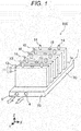
- FIG. 1 is a perspective view showing a cooling structure of a battery module according to the embodiment
- FIG. 2 is a perspective view of a cooling plate according to the embodiment
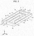
- FIG. 3 is a perspective view of an interior of the cooling plate according to the embodiment
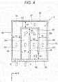
- FIG. 4 is a sectional view of a cooling plate according to Example 1.
- the battery module 100 includes a plurality of cells 10 and a cooling plate (first cooling plate) 1 on which the plurality of cells 10 are arranged.
- the cell 10 is a rechargeable battery which can be recharged and discharged such as a lithium-ion rechargeable battery for example.
- the cell 10 is a so-called prismatic cell, and has a flat box-shaped battery container 11.
- the battery container 11 is composed of a battery can 12 having a laterally long rectangular bottom surface part, a pair of opposed wide surface parts which is bent at a pair of long sides of the bottom surface, and a pair of opposed narrow surface parts which is bent at a pair of short sides of the bottom surface.
- the battery container 11 is also composed of a lid body 13 which closes an upper opening of the battery can 12 and which is laser-welded to the battery can 12.
- the lid body 13 has a laterally long rectangular shape which is substantially equal to that of the bottom surface part of the battery can 12, and both sides of the lid body 13 in its long side direction are provided with a pair of external terminals 14, 14 which are a positive pole and a negative pole.
- a gas release vent 15 is provided at a central position of the lid body 13 in the long side direction. When pressure in the battery container 11 reaches a predetermined value or more, the gas release vent 15 cleavages to release gas in the battery container 11 to outside. In the example shown in FIG.
- the cells 10 are arranged such that the adjacent wide surface parts are opposed to each other, the cells 10 stand from a plate surface 1a of the cooling plate 1, and the bottom surface part of the battery can is attached to the plate surface 1a of the cooling plate 1 in such a coupled state that heat can be conducted.
- the cooling plate 1 has a flat board shape having a predetermined thickness.
- the plate surface 1a has a substantially rectangular flat surface shape as viewed from above.
- the plate surface 1a has a lateral width greater than that of the cell 10, and the plate surface 1a extends in an arrangement direction (Y direction) of the cells 10.
- a channel part 2 through which coolant can flow is provided in the cooling plate 1.
- An end surface part 7B of the cooling plate 1 is provided with a coolant entrance 4 through which coolant flows into the channel part 2 and with a coolant exit 5 through which coolant which passes through the channel part flows out.
- the coolant entrance 4 is placed at a position close to a central portion in a lateral width direction (X direction) of the end surface part 7B, and the coolant exit 5 is placed at a position close to an outer side in the lateral width direction of the end surface part 7B.
- a channel is formed in the channel part 2 so that coolant which flows in from the coolant entrance 4 of the cooling plate 1 passes through the channel and flows out from the coolant exit 5 of the cooling plate 1 through the channel.
- the cooling plate 1 is composed of a container part 7 and an upper plate part 6.
- the upper plate part 6 is made of metal having excellent heat conductivity such as die-cast aluminum, aluminum and magnesium. If electric insulation with respect to the cell 10 is important, it is possible to use plastic having high withstand voltage such as polyester and polyethylene as material of the upper plate part 6.
- the container part 7 also, it is possible to use metal having excellent heat conductivity such as die-cast aluminum, aluminum and magnesium, and plastic having high withstand voltage such as polyester and polyethylene .
- both the upper plate part 6 and container part 7 are made of metal, for example, when they are made of die-cast aluminum, they can be bonded to each other through welding, but they can also be bonded to each other through vacuum furnace brazing.
- the upper plate part 6 is made of plastic and the container part 7 is made of metal, bonding surfaces thereof are provided with appropriate sealing members, e.g., packing such as Teflon (registered trade name).
- sealing members e.g., packing such as Teflon (registered trade name).
- Teflon registered trade name
- the container part 7 has a shallow dish shape having a predetermined depth, and end surface parts 7B, 7C, 7D and 7E circumferentially and continuously stand along end sides of a substantially rectangular (as viewed from above) lower plate 7A.
- the upper plate part 6 has a rectangular flat-plate shape which closes the upper portion of the container part 7.
- the channel part 2 is formed by partitioning an interior of the container part 7 by a partition part 3.
- the partition part 3 includes a first partition part 3A, a second partition part 3B, a third partition part 3C and a fourth partition part 3D.
- Each of the first partition part 3A, the second partition part 3B, the third partition part 3C and the fourth partition part 3D is formed from a plate-shaped member having a predetermined thickness.
- Each of the partition parts has such a height that a lower end of the partition part is fixed to a lower plate 7A of the container part 7 and an upper end of the partition part abuts against a lower surface of the upper plate part 6.
- the channel part 2 forms a channel having a rectangular cross section.
- the channel part 2 is formed by partitioning the interior of the container part 7 by the partition part 3, it is possible to form the channel part 2 more easily than the conventional technique in which a channel part is formed by bending a pipe, and a possibility of leakage of coolant can be lowered.
- the channel part 2 includes a first channel part 2A extending along an arrangement direction (Y direction) of the plurality of cells 10, a second channel part 2C extending in the arrangement direction in parallel to the first channel part 2A with the first partition part 3A interposed between the first channel part 2A and the second channel part 2C on one side of the lateral width direction (X direction) of the plurality of cells 10, and a first communication part 2B which brings one end of the first channel part 2A in the arrangement direction and one end of the second channel part 2C in the arrangement direction into communication with each other, and which turns a flowing direction of coolant in the first channel part 2A and a second channel part 2B.
- the channel part 2 further includes a third channel part 2E extending in the arrangement direction in parallel to the second channel part 2C with the second partition part 3B interposed between the second channel part 2C and the third channel part 2E on one side of the lateral width direction, and a second communication part 2D which brings the other end of the second channel part 2C in the arrangement direction and the other end of the third channel part 2E in the arrangement direction into communication with each other, and which turns a flowing direction of coolant in the second channel part 2C and the third channel part 2E.
- the channel part 2 further includes a fourth channel part 2G extending in the arrangement direction in parallel to the first channel part 2A with a fourth partition part 3D interposed between the first channel part 2A and the fourth channel part 2G on the other side of the lateral width direction, and a third communication part 2F which extends in the lateral width direction on one side of the arrangement direction with respect to the first communication part 2B with a third partition part 3C interposed between the first communication part 2B and the third communication part 2F, which brings one end of the third channel part 2E in the arrangement direction and one end of the fourth channel part 2G in the arrangement direction into communication with each other, and which turns a flowing direction of coolant in the third channel part 2E and the fourth channel part 2G.
- FIG. 4 is a sectional view of a cooling plate according to Example 1, and is a convenient diagram showing a flow of coolant.
- coolant flows into the channel part 2 of the cooling plate 1 from the coolant entrance 4, and straightly moves through the first channel part 2A having a channel width W1 toward one side of the arrangement direction.
- the coolant is deviated in the first communication part 2B having a channel width W2, a flowing direction is turned, and the coolant straightly moves through the second channel part 2C having a channel width W3 toward the other side of the arrangement direction.
- the coolant is deviated in the second communication part 2D having a channel width W4, the flowing direction is turned, the coolant straightly moves through the third channel part 2E having a channel width W5 toward the one side of the arrangement direction, the coolant is deviated in the third communication part 2F having a channel width W6, the flowing direction is turned, the coolant straightly moves through the fourth channel part 2G having a channel width W7 toward the other side of the arrangement direction, and the coolant is discharged from the coolant exit 5.
- Example 1 sizes of the channel width W1 to the channel width W7 are set equally to each other. Hence, flowing speed of coolant is not increased or reduced in the channel part 2, and average speeds of flow in all of channels from the first channel part 2A to the fourth channel part 2G are the same.
- Temperature of coolant in the channel part 2 becomes the lowest in the vicinity of the coolant entrance 4. Coolant cools heat of the five cells 10 which generate heat by the recharging or discharging operation shown in FIG. 1 . The coolant cools this heat of the five cells 10 through the bottom surface parts of the cells 10 and the upper plate part 6 of the cooling plate 1, and the coolant flows toward the coolant exit 5 while absorbing heat, and gradually rises its temperature.
- Example 1 the first channel part 2A and the second channel part 2C extend along the arrangement direction in parallel to each other with the first partition part 3A interposed therebetween, the one end of the first channel part 2A in the arrangement direction and the one end of the second channel part 2C in the arrangement direction are in communication with each other through the first communication part 2B, and a flowing direction of coolant in the first channel part 2A and the second channel part 2C is turned.
- Temperature of coolant in the downstream side second channel part 2C is higher than that in the upstream side first channel part 2A, but the first channel part 2A and the second channel part 2C extend in the arrangement direction with the first partition part 3A interposed therebetween, and a direction of coolant flowing through the first channel part 2A and a direction of coolant flowing through the second channel part 2C are opposite from each other.
- the upstream portion of the first channel part 2A having low temperature coolant and the downstream portion of the second channel part 2C having the high temperature coolant can be opposed to each other, heat can be exchanged, through the first partition part 3A, between the coolant flowing through the first channel part 2A and the coolant flowing through the second channel part 2C, and the heat can be exchanged in the arrangement direction of the first channel part 2A and the second channel part 2C. Therefore, the temperature rise of coolant flowing through the downstream portion of the second channel part 2C can be lowered.
- the second channel part 2C and the third channel part 2E extend along the arrangement direction with the second partition part 3B interposed therebetween, the other end of the second channel part 2C of the arrangement direction and the other end of the third channel part 2E of the arrangement direction are in communication with each other through the second communication part 2D, and the flowing direction of coolant in the second channel part 2C and the third channel part 2E is turned.
- a direction of coolant flowing through the second channel part 2C and a direction of coolant flowing through the third channel part 2E are opposite from each other, the upstream portion of the second channel part 2C having low temperature coolant and the downstream portion of the third channel part 2E having high temperature coolant can be opposed to each other, heat can be exchanged, through the second partition part 3B, between coolant flowing through the second channel part 2C and coolant flowing through the third channel part 2E, and the heat can be exchanged in the arrangement direction of the second channel part 2C and the third channel part 2E. Therefore, the temperature rise of coolant flowing through the downstream portion of the third channel part 2E can be made small.
- the first communication part 2B and the third communication part 2F extend in parallel to each other along the lateral width direction (X direction) with the third partition part 3C interposed therebetween, and a direction of coolant flowing through the first communication part 2B and a direction of coolant flowing through the third communication part 2F are opposite from each other.
- the upstream portion of the first communication part 2B having the low temperature coolant and the downstream portion of the third communication part 2F having the high temperature coolant can be opposed to each other. Therefore, heat can be exchanged, through the third partition part 3C, between the coolant flowing through the first communication part 2B and coolant flowing through the third communication part 2F, and the heat can be exchanged in the lateral width direction of the first communication part 2B and the third communication part 2F.
- temperature rise of coolant flowing through the downstream portion of the third communication part 2F can be made small.
- the fourth channel part 2G extends in parallel in the arrangement direction along the first channel part 2A with the fourth partition part 3D interposed between the fourth channel part 2G and the first channel part 2A, the one end of the fourth channel part 2G in the arrangement direction and the one end of the third channel part 2E in the arrangement direction are in communication with each other through the third communication part 2F, and the flowing direction of coolant in the third channel part 2E and the fourth channel part 2G is turned.
- the first channel part 2A and the fourth channel part 2G extend in parallel to each other along the arrangement direction with the fourth partition part 3D interposed therebetween.
- a direction of coolant flowing through the first channel part 2A and a direction of coolant flowing through the fourth channel part 2G are opposite from each other, and the upstream portion of the first channel part 2A having the low temperature coolant and the downstream portion of the fourth channel part 2G having the high temperature coolant can be opposed to each other.
- heat can be exchanged, through the fourth partition part 3D, between coolant flowing through the first channel part 2A and coolant flowing through the fourth channel part 2G, and the heat can be exchanged in the arrangement direction of the first channel part 2A and the fourth channel part 2G. Therefore, the temperature rise of coolant flowing through the downstream portion of the fourth channel part 2G can be made small.
- Example 1 since low temperature coolant and high temperature coolant exchange heat through all of the partition parts 3A to 3D, temperature rise of coolant can be made small. Therefore, temperature rise of coolant in the channel part 2 can be made small, variation in a temperature distribution in the plate surface 1a of the cooling plate 1 can be reduced, and the temperature distribution can be made more uniform.
- the cell 10 located at a center of the lateral width direction has higher temperature than the cells 10 located at both ends of the lateral width direction.
- the cooling plate 1 is configured such that entrance coolant 2 is placed at a position close to a substantially central portion of the lateral width direction of the cooling plate 1, and the first channel part 2A and the second channel part 2C are placed such that they extend along the arrangement direction of the cells 10. According to this, high temperature portions of the plurality of cells 10 can be cooled by coolant having lower temperature, and it is possible to cool the cells 10 efficiently.
- the cooling plate 1 has such a structure that coolant flows in from a substantially central portion in the lateral width direction of the end surface part 7B, the coolant passes through the center portion of the cooling plate 1 while exchanging heat through the partition part 3, and the coolant flows out in a direction opposite from the flowing direction of the coolant entrance 4. Therefore, it is possible to effectively cool the center portion of the cooling plate 1, and the end of the cooling plate 1 can exchange heat with coolant of the center portion having low temperature through the partition parts 3B and 3D.
- surface temperatures of the cooling plate 1 can be made further uniform, and temperatures of the plurality of cells 10 which are in thermally contact with the cooling plate 1 can be made uniform.
- Example 1 Although the module structure in which the prismatic cells 10 are vertically placed on the cooling plate 1 is indicated in Example 1, the present invention is not limited to this structure, and the invention can be applied to any structures in which cylindrical cells or cells having other shapes can thermally be in contact through a cooling plate of this structure.
- the prismatic cells 10 may be placed sideways on the cooling plate 1 so that the wide surfaces of the cells 10 come into thermal contact with the plate surface 1a of the cooling plate 1. According to this, it is possible to lower the height of the battery module 100, and there is an effect that the battery module can be made compact.
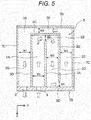
- FIG. 5 is a sectional view of a cooling plate according to Example 2, and is a convenient diagram showing a flow of coolant.
- Example 2 is characterized in that narrow portions having narrow channel cross sections are provided at intermediate portions of a channel of a channel part 2, speed of a flow of coolant is increased at the narrow portion, and after the coolant passes through the narrow portion, speed thereof is reduced, and the speed of coolant flowing through the channel part 2 is changed such that the speed is repeatedly increased and reduced.
- Example 2 A basic configuration of Example 2 is similar to that of Example 1. However, as compared with the configuration of Example 1, the channel widths W2, W4 and W6 of the first communication part 2B, the second communication part 2D and the third communication part 2F are smaller than the channel widths W1, W3, W5 and W7 of the first channel part 2A, the second channel part 2C, the third channel part 2E and the fourth channel part 2G, the narrow portions having the narrow channel cross sections are formed at the locations of the channel width W2, the channel width W4 and the channel width W6, and when coolant passes through the narrow portion, speed of a flow of the coolant is increased, and after the coolant passes through the narrow portion, speed thereof is reduced.
- Coolant cools the entire cooling plate 1 along the flowing direction while repeatedly increasing and reducing the flowing speed, and the coolant is discharged from the coolant exit 5.
- flowing speed of coolant is increased at the narrow portions having narrow channel width (W2, W4 and W6), the heat transfer in the channel part 2 is enhanced and cooling performance is enhanced.
- Other channel widths W1, W3, W5 and W7 are equal to each other as in Example 1.
- the channel widths W2, W4 and W6 of the first communication part 2B, the second communication part 2D and the third communication part 2F are made smaller than the channel widths W1, W3, W5 and W7 of the first channel part 2A, the second channel part 2C, the third channel part 2E and the fourth channel part 2G, the flowing speed of coolant is increased or reduced in the channel part 2 so that hot spot caused by retention of coolant in the cooling plate 1 is prevented from being generated. Therefore, it is possible to uniform temperatures of the plurality of cells 10 which are in thermal contact with the cooling plate 1.
- Example 2 by employing the structure in which flowing speed of coolant is alternately increased and reduced in the channel part 2, it is possible to enhance the heat transfer in the channel part 2. According to this, it is possible to further effectively uniform the surface temperature of the cooling plate 1, and it is possible to further uniform temperatures of the plurality of cells 10 which are in thermal contact with the cooling plate 1. Therefore, it is possible to provide a reliable and compact battery module structure in which temperature rise of the cells caused by the recharging and discharging operations of the cells 10 is further reduced and made uniform, and variation in the recharging and discharging amounts between the cells and battery lives is further reduced.
- FIG. 6 is a sectional view of a cooling plate according to Example 3, and is a convenient diagram showing a flow of coolant.
- Example 3 is characterized in that in addition to the configuration of above-described Example 2, a channel cross-sectional area of the channel part 2 on the upstream side is made narrower than that on the downstream side so that flowing speed on the downstream side of the channel part 2 is increased.
- Example 3 A basic configuration of Example 3 is similar to that of Example 2. However, as compared with the configuration of Example 2, the channel width W1 of the first channel part 2A is larger than the channel width W3 of the second channel part 2C and the channel width W5 of the third channel part 2E, and the channel width W7 of the fourth channel part 2G is smaller than the channel width W3 of the second channel part 2C and the channel width W5 of the third channel part 2E.
- Example 3 flowing speed in the fourth channel part 2G on the side of the coolant exit 5 where the temperature of coolant is the highest is increased, a heat transfer coefficient with respect to the first channel part 2A on the side of the coolant entrance 4 where temperature of coolant is the lowest is enhanced, and temperature of coolant in the coolant exit 5 can further be reduced. Therefore, in addition to the effects described in Example 2, there are effects that it is possible to further uniform surface temperature of the cooling plate 1, and to further uniform temperatures of the plurality of cells 10 which are in thermal contact with the cooling plate.
- Cooling plates 1 of the structures of Examples 1 to 3 respectively shown FIGS. 4 , 5 and 6 were prepared.
- Material of the cooling plates 1 was corrosion-resistant aluminum, sizes of the cooling plates 1 were a lateral width (X direction) of 120 mm, a length (Y direction) of about 200 mm, and thicknesses of the upper plate part 6 and the partition part 3 of the cooling plate 1 were each 3 mm.
- a height of a channel was 6 mm, the channel widths W1 to W7 of Example 1 were set to 27 mm, and the channel widths W2, W4 and W6 of Example 2 were set to 20 mm.
- the channel width W1 was set to 32 mm, and the channel width W7 was set to 22 mm. Widths of other channels were the same as those of Example 2, and they were compared with each other and studied.
- a flow rate of coolant (water solution of ethylene glycol 50%) was 3 liters/minute, entrance temperature of coolant was 20°C and the analysis was carried out. As a heat value, heat input of about 200 W was set uniformly for the upper plate part 6 of the cooling plate 1.
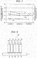
- FIG. 7 shows a result of the analysis.
- a lateral axis shows Examples 1 to 3.
- temperature variation of the cooling plate 1 means a temperature difference ( ⁇ T) between the highest surface temperature (Tmax) and the lowest surface temperature (Tmin) on the plate surface 1a (surface portion of cooling plate 1 which comes into thermal contact with cell 10).
- FIG. 7 shows that in the embodiment of the present invention, i.e., in the coolant channel structure (Examples 2 and 3) that an interior of the cooling plate 1 is cooled in the flowing direction while repeating deceleration and acceleration of flowing speed, the temperature of the cooling plate 1 is varied and the lowest surface temperature becomes low as compared with Example 1 in which the channel part 2 is configured with a simple constant channel width. Therefore, this analysis result shows that if the channel width is changed so that acceleration and deceleration of flowing speed of coolant are alternately carried out in the channel part 2 to suppress a case where the flow is uniformly developed, it is possible to enhance the heat transfer of the cooling plate 1.
- FIG. 8 is a side view of a battery module according to Example 4.
- Example 4 a plurality of cells 10 are in thermal contact with the cooling plate 1 through adhesive 18.
- a main component of the adhesive 18 is epoxy resin having excellent heat conductivity (equal to or higher than 1 W (m ⁇ K) and withstand voltage is high for example).
- thermal contact between the cells 10 and the cooling plate 1 becomes excellent and even if the cells 10 are short-circuited, reliability of the module 100 can be enhanced. Even if the cells 10 are brought into thermal contact through heat transfer plastic having high withstand voltage instead of the adhesive 18, the same effects are exerted, and in addition to the above-described effects, there is also an effect that the reliability can further be enhanced.
- FIG. 9 is a side view of a battery module according to Example 5.
- Example 5 shows a structure in which states of natural heat dissipation from the plurality of cells 10 are made the same between the cells 10 to further uniform the temperatures of the cells 10.
- resin spacers 16 having the same thickness are interposed between the cells 10.
- a pair of metal end plates 17, 17 is provided to sandwich a group of cells formed by each cell 10 and the spacer 16 from both sides in the arrangement direction and to fix and tie the group of cells. Therefore, in Example 5, of the heat value of the cells 10, conditions caused by the natural heat dissipation can also be made the same, and in addition to the Examples, there is an effect that temperatures of the plurality of cells 10 can be made further uniform.
- FIG. 10 is a perspective view showing a battery module according to Example 6.
- Example 6 A basic configuration of Example 6 is similar to that of Example 1. However, a pair of second cooling plates 21 is provided on both ends of the cells 10, and the second cooling plates 21 are in thermal contact with narrow surface parts of the cells 10. A lower end of the second cooling plate 21 is in thermal contact also with the plate surface 1a of the cooling plate 1, and the second cooling plate 21 has almost the same height as that of the lid body 13 of the cell 10.
- the second cooling plate 21 is formed from a plate-shaped member having a predetermined thickness which is made of metal material having high heat transfer such as aluminum alloy.
- Example 6 the second cooling plates 21 are cooled by heat transfer from the cooling plate 1, and the cells 10 are indirectly cooled by the second cooling plates 21.
- the spacers 16 and the end plates 17 are provided, and the thermal contact condition can be made more excellent. Therefore, in addition to the effects of above-described Examples, there is an effect that temperatures of the plurality of cells 10 can be made further uniform.
- FIG. 11A is a perspective view showing a battery module according to Example 7, and FIG. 11B is a sectional view of a second cooling plate.
- Example 7 is characterized in that each of the pair of second cooling plates 21 in Example 6 is provided with a channel part 2 through which coolant flows like the cooling plate 1.
- the second cooling plates 21 is provided with a coolant entrance 22 at a position of the second cooling plate 21 close to an upper portion in a cell height direction of the end surface of the end surface part 7B side, and with a coolant exit 23 at a position of the second cooling plate 21 close to a central portion in the cell height direction.
- the coolant entrance 22 is in communication with the fourth channel part 2G
- the coolant exit 23 is in communication with the first channel part 2A.
- the channel part 2 is configured such that the fourth channel part 2G is placed on an upper side in the cell height direction and the third channel part 2E is placed on a lower side (on the side of cooling plate 21) in the cell height direction.
- Coolant flows into the channel part 2 of the second cooling plate 21 from the coolant entrance 22, and straightly moves through the fourth channel part 2G toward one side of the arrangement direction.
- the coolant is deviated in the third communication part 2F and the flowing direction is turned, and the coolant straightly moves through the third channel part 2E toward the other side of the arrangement direction.
- the coolant is deviated in the second communication part 2D and the flowing direction is turned, -the coolant straightly moves through the second channel part 2C toward the one side of the arrangement direction, the coolant is deviated in the first communication part 2B and the flowing direction is turned, the coolant straightly moves through the first channel part 2A toward the other side of the arrangement direction, and the coolant is discharged from the coolant exit 23.
- the channel part 2 has such a structure that the channel widths W2, W4 and W6 of the first communication part 2B, the second communication part 2D and the third communication part 2F are made smaller than the channel widths W1, W3, W5 and W7 of the first channel part 2A, the second channel part 2C, the third channel part 2E and the fourth channel part 2G, narrow portions where channel cross-sectional areas are narrow are formed at locations of the channel width W2, the channel width W4 and the channel width W6, and when coolant passes through the narrow portions, flow of the coolant is accelerated and after the coolant passes the narrow portions, flow of the coolant is decelerated.
- the coolant cools the entire cooling plate 1 along the flowing direction while repeating the acceleration and deceleration of flow, and is discharged from the coolant exit 23.
- Example 7 since flowing speed of coolant is accelerated at the narrow portions (W2, W4 and W6) where the channel width is narrow, heat transfer in the channel part 2 is enhanced, and the cooling performance is enhanced.
- Other channel widths W1, W3, W5 and W7 have the same sizes.
- Example 7 coolant having the same temperature as that of coolant of the cooling plate 1 can be introduced into the coolant entrance 22 of the second cooling plate 21, and both side surfaces of the cells 10 can be cooled. Therefore, in addition to the effects of the above-described Examples, there are effects that it is possible to further lower the temperatures of the cells 10 and the temperatures of the cells 10 can be made uniform.
- Temperature of cells 10 on the side of the lid body 13 of the battery can 12 is higher than that of cells 10 on the side of the bottom surface part of the battery can 12.
- coolant flows into the channel part 2 from the coolant entrance 22 provided at the position close to the upper portion of the end surface of the end surface part 7B side of the second cooling plates 21 in the height direction, and the coolant is discharged from the coolant exit 23 provided at the position close to the central portion in the height direction. Therefore, it is possible to cool the cells 10 efficiently.
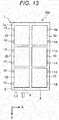
- FIG. 12 is a perspective view showing an outward appearance of a battery module according to Example 8.
- the battery module 100 has a group of a plurality of cells 10 laminated on one another through spacers 16 therebetween (see FIG. 9 ). Both sides of the battery module 100 in the arrangement direction are covered with the pair of end plates 17. A lower portion of the battery module 100 is covered with the cooling plate 1, and an upper portion of the battery module 100 is covered with an upper cover 41. Both sides of the battery module 100 in the lateral width direction are covered with the pair of side plates 42.
- the cooling plate 1, the pair of end plates 17, the upper cover 41 and the pair of side plates 42 are integrally coupled to one another through four coupling members 43.
- Each of the coupling members 43 has a length extending between the pair of end plates 17, 17 in the arrangement direction.
- the upper cover 41 has a gas release passage 51 extending in the arrangement direction.
- the gas release passage 51 is in communication with the gas release vents 15 of the cells 10, and when the cell is in an abnormal condition, gas discharged from the gas release vent 15 is made to flow into gas release passage 51, and the gas is discharged out from the gas release pipe 52.
- the cooling plate 1 is provided on a lower portion of the battery module 100, and both ends of the battery module 100 in the lateral width direction are sandwiched by the pair of side plates 42 and hermetically closed.
- Example 8 the flow of coolant is the same as those of the Examples, there is a similar effect concerning the cooling performance of the cells, and there is an effect that it is possible to provide a further compact and safe battery module.
- the embodiment of the present invention has been described in detail, the invention is not limited to the embodiment, and a design of the embodiment can variously be modified within a range not departing from the spirit of the invention described in claims.
- the embodiment is described in detail for easily describing the invention, and the invention is not limited to a structure having all of the described configurations.
- a portion of a configuration of a certain embodiment can be replaced by a configuration of another embodiment, and a configuration of a certain embodiment can be added to a configuration of another embodiment. It is possible to add a configuration to a portion of a configuration of each of the embodiments, and to delete a portion of a configuration of the embodiment, and a portion of a configuration of the embodiment can be replaced by another configuration.
Description
- The present invention relates to a battery module configured by connecting a plurality of rechargeable/dischargeable cells to each other.
- A battery module provided in a hybrid vehicle, an electric vehicle and the like as a power source device is configured by connecting, to each other, a plurality of cells such as a lithium-ion rechargeable battery, a nickel-hydride rechargeable battery and a nickel-cadmium rechargeable battery for example. Generally, charge-and-discharge current of a battery module is large, heat values of the cells also become large and as a result, temperature of the cell itself also largely rises. It is preferable that temperature rise of a cell is suppressed as small as possible in terms of battery life, and it is necessary to swiftly cool the battery.
- As a method of swiftly cooling the plurality of cells, there is one using liquid coolant. For example, there is known a method that a plurality of cells are coupled to each other and arranged on one surface of a cooling plate having a channel for coolant through an insulation sheet such that the cells can be cooled, and coolant is supplied to the cooling plate to cool the cells (see
PTL 1 for example). As another method having a partition, there is also known a cooling method using a lightweight thin channel compact which can easily be produced by forming a coolant channel from a laminated film (seePTL 2 for example). -
- PTL 1:
JP 2010-62130 A - PTL 2:
JP 2004-207458 A - In
US 2011/206948 A1 , a power source apparatus with electrical components disposed in the battery blocks is described. The battery blocks are made up of a plurality of battery cells connected in battery stacks and an outer case that holds the battery blocks. A block circuit board is provided to control the battery cells that make up each battery stack. Further, a cooling plate with coolant plumbing for each batter block is provided. - In
US 5 985 483 A , a sealed battery block is described. The battery includes a container made of plastic material and made up of a lid and of a case subdivided into wells by at least one partition. The battery is provided with a cooling system including two cheek plates made of plastic material and co-operating with the outside faces of the walls of the case. - In
US 5 569 552 A , a lead-acid storage battery for starting lightning and ignition applications is described. There is provided an injection-molded integral plastic container having a multi-wall configuration in which an inner container includes the cell elements of the battery. - However, in the case of a coolant passage having a constant cross section and extending straightly like a coolant passage described in
PTL 1, flow of coolant in the coolant passage is uniform, heat transfer is small, a temperature distribution is prone to be formed in a flowing direction of coolant of the cooling plate, and it is difficult to sufficiently secure the temperature uniformity between cells in a battery module. - An object of the invention is to provide a reliable and compact battery module in which the conventional technique is improved, excellent heat transfer is established between coolant and a cooling plate by a coolant channel having a relatively simple structure, a temperature distribution of the cooling plate is made further uniform, temperatures of a plurality of cells are made uniform, temperature rise of the cells caused by recharging and discharging operations of the cells is reduced and is made further uniform, and variation in recharging and discharging amounts and cell lives between the cells is reduced.
- To solve the problem, configurations described in claims are employed. The invention provides a battery module comprising a plurality of cells, a cooling plate having a plate surface on which the plurality of cells are arranged, and a channel part which is formed in the cooling plate and through which coolant can flow, wherein the cooling plate further includes:a coolant entrance placed at a position close to a central portion in a lateral width direction of the end surface part,the coolant exit through which the coolant flows out from in a direction opposite from a direction of the coolant flowing through the coolant entrance , the coolant exit is placed at a position close to an outer side in the lateral width direction of the end surface part, wherein the channel part includes a first channel part, a second channel part, a third channel part and a fourth channel part which extend in an arrangement direction of the plurality of cells, and a first communication part which is configured to turn a flowing direction of the coolant in the first channel part and the second channel part, a second communication part which is configured to turn a flowing direction of the coolant in the second channel part and the third channel part, and a third communication part which is configured to turn a flowing direction of the coolant in the third channel part and the fourth channel part ,wherein the coolant in the first channel part - and the coolant in the second channel part flow in opposite directions on opposing sides of a first partition part, the coolant in the second channel part and the coolant in the third channel part flow in opposite directions on opposing sides of a second partition part, the coolant in the first communication part and the coolant in the third communication part flow in opposite directions on opposing sides of a third partition part, the coolant in. the fourth channel part and the coolant in the first channel part flow in opposite directions on opposing sides of a fourth partition part,characterized in that the fourth channel part extends in parallel in the arrangement direction along the first channel part with the fourth partition part formed from a plate-shaped member interposed between the fourth channel part and the first channel part , the channel part is configured to allow heat exchange between coolant in the first channel part and coolant in the fourth channel part, through the forth partition part.
-
- [
FIG. 1] FIG. 1 is a perspective view for describing a cooling structure of a battery module according to an embodiment. - [
FIG. 2] FIG. 2 is a perspective view of a cooling plate according to the embodiment. - [
FIG. 3] FIG. 3 is a perspective view of an interior of the cooling plate according to the embodiment. - [
FIG. 4] FIG. 4 is a sectional view of a cooling plate according to Example 1. - [
FIG. 5] FIG. 5 is a sectional view of a cooling plate according to Example 2. - [
FIG. 6] FIG. 6 is a sectional view of a cooling plate according to Example 6. - [
FIG. 7] FIG. 7 is a graph showing an analysis result showing effects of Examples 1 to 3. - [
FIG. 8] FIG. 8 is a side view of a battery module according to Example 4. - [
FIG. 9] FIG. 9 is a side view of a battery module according to Example 5. - [
FIG. 10] FIG. 10 is a perspective view of a battery module according to Example 6. - [
FIG. 11A] FIG. 11A is a perspective view of a battery module according to Example 7. - [
FIG. 11B] FIG. 11B is a sectional view of a side plate according to Example 7. - [
FIG. 12] FIG. 12 is a perspective view showing an outward appearance of a battery module according to Example 8. - [
FIG. 13] FIG. 13 is a plan view showing another example of the battery module according to the embodiment. - Next, an embodiment will be described below using the drawings.
-
FIG. 1 is a perspective view showing a cooling structure of a battery module according to the embodiment,FIG. 2 is a perspective view of a cooling plate according to the embodiment,FIG. 3 is a perspective view of an interior of the cooling plate according to the embodiment, andFIG. 4 is a sectional view of a cooling plate according to Example 1. - As shown in
FIG. 1 , thebattery module 100 includes a plurality ofcells 10 and a cooling plate (first cooling plate) 1 on which the plurality ofcells 10 are arranged. Thecell 10 is a rechargeable battery which can be recharged and discharged such as a lithium-ion rechargeable battery for example. Thecell 10 is a so-called prismatic cell, and has a flat box-shaped battery container 11. The battery container 11 is composed of a battery can 12 having a laterally long rectangular bottom surface part, a pair of opposed wide surface parts which is bent at a pair of long sides of the bottom surface, and a pair of opposed narrow surface parts which is bent at a pair of short sides of the bottom surface. The battery container 11 is also composed of alid body 13 which closes an upper opening of the battery can 12 and which is laser-welded to the battery can 12. - The
lid body 13 has a laterally long rectangular shape which is substantially equal to that of the bottom surface part of the battery can 12, and both sides of thelid body 13 in its long side direction are provided with a pair ofexternal terminals gas release vent 15 is provided at a central position of thelid body 13 in the long side direction. When pressure in the battery container 11 reaches a predetermined value or more, the gas release vent 15 cleavages to release gas in the battery container 11 to outside. In the example shown inFIG. 1 for example, fivecells 10 are arranged such that the adjacent wide surface parts are opposed to each other, thecells 10 stand from aplate surface 1a of thecooling plate 1, and the bottom surface part of the battery can is attached to theplate surface 1a of thecooling plate 1 in such a coupled state that heat can be conducted. - The
cooling plate 1 has a flat board shape having a predetermined thickness. Theplate surface 1a has a substantially rectangular flat surface shape as viewed from above. Theplate surface 1a has a lateral width greater than that of thecell 10, and theplate surface 1a extends in an arrangement direction (Y direction) of thecells 10. As shown inFIG. 3 , achannel part 2 through which coolant can flow is provided in thecooling plate 1. Anend surface part 7B of thecooling plate 1 is provided with acoolant entrance 4 through which coolant flows into thechannel part 2 and with acoolant exit 5 through which coolant which passes through the channel part flows out. Thecoolant entrance 4 is placed at a position close to a central portion in a lateral width direction (X direction) of theend surface part 7B, and thecoolant exit 5 is placed at a position close to an outer side in the lateral width direction of theend surface part 7B. A channel is formed in thechannel part 2 so that coolant which flows in from thecoolant entrance 4 of thecooling plate 1 passes through the channel and flows out from thecoolant exit 5 of thecooling plate 1 through the channel. - As shown in
FIG. 2 , thecooling plate 1 is composed of acontainer part 7 and anupper plate part 6. Theupper plate part 6 is made of metal having excellent heat conductivity such as die-cast aluminum, aluminum and magnesium. If electric insulation with respect to thecell 10 is important, it is possible to use plastic having high withstand voltage such as polyester and polyethylene as material of theupper plate part 6. As thecontainer part 7 also, it is possible to use metal having excellent heat conductivity such as die-cast aluminum, aluminum and magnesium, and plastic having high withstand voltage such as polyester and polyethylene . When both theupper plate part 6 andcontainer part 7 are made of metal, for example, when they are made of die-cast aluminum, they can be bonded to each other through welding, but they can also be bonded to each other through vacuum furnace brazing. When theupper plate part 6 is made of plastic and thecontainer part 7 is made of metal, bonding surfaces thereof are provided with appropriate sealing members, e.g., packing such as Teflon (registered trade name). When both theupper plate part 6 andcontainer part 7 are made of plastic, they may be adhered to each other through adhesive or the like. - As shown in
FIG. 3 , thecontainer part 7 has a shallow dish shape having a predetermined depth, and endsurface parts lower plate 7A. Theupper plate part 6 has a rectangular flat-plate shape which closes the upper portion of thecontainer part 7. - The
channel part 2 is formed by partitioning an interior of thecontainer part 7 by apartition part 3. Thepartition part 3 includes afirst partition part 3A, asecond partition part 3B, athird partition part 3C and afourth partition part 3D. Each of thefirst partition part 3A, thesecond partition part 3B, thethird partition part 3C and thefourth partition part 3D is formed from a plate-shaped member having a predetermined thickness. Each of the partition parts has such a height that a lower end of the partition part is fixed to alower plate 7A of thecontainer part 7 and an upper end of the partition part abuts against a lower surface of theupper plate part 6. Thechannel part 2 forms a channel having a rectangular cross section. - Since the
channel part 2 is formed by partitioning the interior of thecontainer part 7 by thepartition part 3, it is possible to form thechannel part 2 more easily than the conventional technique in which a channel part is formed by bending a pipe, and a possibility of leakage of coolant can be lowered. - The
channel part 2 includes afirst channel part 2A extending along an arrangement direction (Y direction) of the plurality ofcells 10, a second channel part 2C extending in the arrangement direction in parallel to thefirst channel part 2A with thefirst partition part 3A interposed between thefirst channel part 2A and the second channel part 2C on one side of the lateral width direction (X direction) of the plurality ofcells 10, and afirst communication part 2B which brings one end of thefirst channel part 2A in the arrangement direction and one end of the second channel part 2C in the arrangement direction into communication with each other, and which turns a flowing direction of coolant in thefirst channel part 2A and asecond channel part 2B. - The
channel part 2 further includes athird channel part 2E extending in the arrangement direction in parallel to the second channel part 2C with thesecond partition part 3B interposed between the second channel part 2C and thethird channel part 2E on one side of the lateral width direction, and asecond communication part 2D which brings the other end of the second channel part 2C in the arrangement direction and the other end of thethird channel part 2E in the arrangement direction into communication with each other, and which turns a flowing direction of coolant in the second channel part 2C and thethird channel part 2E. - The
channel part 2 further includes afourth channel part 2G extending in the arrangement direction in parallel to thefirst channel part 2A with afourth partition part 3D interposed between thefirst channel part 2A and thefourth channel part 2G on the other side of the lateral width direction, and athird communication part 2F which extends in the lateral width direction on one side of the arrangement direction with respect to thefirst communication part 2B with athird partition part 3C interposed between thefirst communication part 2B and thethird communication part 2F, which brings one end of thethird channel part 2E in the arrangement direction and one end of thefourth channel part 2G in the arrangement direction into communication with each other, and which turns a flowing direction of coolant in thethird channel part 2E and thefourth channel part 2G. -
FIG. 4 is a sectional view of a cooling plate according to Example 1, and is a convenient diagram showing a flow of coolant. - As shown in
FIG. 4 , coolant flows into thechannel part 2 of thecooling plate 1 from thecoolant entrance 4, and straightly moves through thefirst channel part 2A having a channel width W1 toward one side of the arrangement direction. The coolant is deviated in thefirst communication part 2B having a channel width W2, a flowing direction is turned, and the coolant straightly moves through the second channel part 2C having a channel width W3 toward the other side of the arrangement direction. Then, the coolant is deviated in thesecond communication part 2D having a channel width W4, the flowing direction is turned, the coolant straightly moves through thethird channel part 2E having a channel width W5 toward the one side of the arrangement direction, the coolant is deviated in thethird communication part 2F having a channel width W6, the flowing direction is turned, the coolant straightly moves through thefourth channel part 2G having a channel width W7 toward the other side of the arrangement direction, and the coolant is discharged from thecoolant exit 5. - Therefore, if the flow is expressed by a shape, a substantially L-shaped coolant channel continues. In Example 1, sizes of the channel width W1 to the channel width W7 are set equally to each other. Hence, flowing speed of coolant is not increased or reduced in the
channel part 2, and average speeds of flow in all of channels from thefirst channel part 2A to thefourth channel part 2G are the same. - Temperature of coolant in the
channel part 2 becomes the lowest in the vicinity of thecoolant entrance 4. Coolant cools heat of the fivecells 10 which generate heat by the recharging or discharging operation shown inFIG. 1 . The coolant cools this heat of the fivecells 10 through the bottom surface parts of thecells 10 and theupper plate part 6 of thecooling plate 1, and the coolant flows toward thecoolant exit 5 while absorbing heat, and gradually rises its temperature. - In Example 1, the
first channel part 2A and the second channel part 2C extend along the arrangement direction in parallel to each other with thefirst partition part 3A interposed therebetween, the one end of thefirst channel part 2A in the arrangement direction and the one end of the second channel part 2C in the arrangement direction are in communication with each other through thefirst communication part 2B, and a flowing direction of coolant in thefirst channel part 2A and the second channel part 2C is turned. - Temperature of coolant in the downstream side second channel part 2C is higher than that in the upstream side
first channel part 2A, but thefirst channel part 2A and the second channel part 2C extend in the arrangement direction with thefirst partition part 3A interposed therebetween, and a direction of coolant flowing through thefirst channel part 2A and a direction of coolant flowing through the second channel part 2C are opposite from each other. Therefore, the upstream portion of thefirst channel part 2A having low temperature coolant and the downstream portion of the second channel part 2C having the high temperature coolant can be opposed to each other, heat can be exchanged, through thefirst partition part 3A, between the coolant flowing through thefirst channel part 2A and the coolant flowing through the second channel part 2C, and the heat can be exchanged in the arrangement direction of thefirst channel part 2A and the second channel part 2C. Therefore, the temperature rise of coolant flowing through the downstream portion of the second channel part 2C can be lowered. - Similarly, the second channel part 2C and the
third channel part 2E extend along the arrangement direction with thesecond partition part 3B interposed therebetween, the other end of the second channel part 2C of the arrangement direction and the other end of thethird channel part 2E of the arrangement direction are in communication with each other through thesecond communication part 2D, and the flowing direction of coolant in the second channel part 2C and thethird channel part 2E is turned. Therefore, a direction of coolant flowing through the second channel part 2C and a direction of coolant flowing through thethird channel part 2E are opposite from each other, the upstream portion of the second channel part 2C having low temperature coolant and the downstream portion of thethird channel part 2E having high temperature coolant can be opposed to each other, heat can be exchanged, through thesecond partition part 3B, between coolant flowing through the second channel part 2C and coolant flowing through thethird channel part 2E, and the heat can be exchanged in the arrangement direction of the second channel part 2C and thethird channel part 2E. Therefore, the temperature rise of coolant flowing through the downstream portion of thethird channel part 2E can be made small. - The
first communication part 2B and thethird communication part 2F extend in parallel to each other along the lateral width direction (X direction) with thethird partition part 3C interposed therebetween, and a direction of coolant flowing through thefirst communication part 2B and a direction of coolant flowing through thethird communication part 2F are opposite from each other. Hence, the upstream portion of thefirst communication part 2B having the low temperature coolant and the downstream portion of thethird communication part 2F having the high temperature coolant can be opposed to each other. Therefore, heat can be exchanged, through thethird partition part 3C, between the coolant flowing through thefirst communication part 2B and coolant flowing through thethird communication part 2F, and the heat can be exchanged in the lateral width direction of thefirst communication part 2B and thethird communication part 2F. Hence, temperature rise of coolant flowing through the downstream portion of thethird communication part 2F can be made small. - The
fourth channel part 2G extends in parallel in the arrangement direction along thefirst channel part 2A with thefourth partition part 3D interposed between thefourth channel part 2G and thefirst channel part 2A, the one end of thefourth channel part 2G in the arrangement direction and the one end of thethird channel part 2E in the arrangement direction are in communication with each other through thethird communication part 2F, and the flowing direction of coolant in thethird channel part 2E and thefourth channel part 2G is turned. Thefirst channel part 2A and thefourth channel part 2G extend in parallel to each other along the arrangement direction with thefourth partition part 3D interposed therebetween. Therefore, a direction of coolant flowing through thefirst channel part 2A and a direction of coolant flowing through thefourth channel part 2G are opposite from each other, and the upstream portion of thefirst channel part 2A having the low temperature coolant and the downstream portion of thefourth channel part 2G having the high temperature coolant can be opposed to each other. Hence, heat can be exchanged, through thefourth partition part 3D, between coolant flowing through thefirst channel part 2A and coolant flowing through thefourth channel part 2G, and the heat can be exchanged in the arrangement direction of thefirst channel part 2A and thefourth channel part 2G. Therefore, the temperature rise of coolant flowing through the downstream portion of thefourth channel part 2G can be made small. - In Example 1, since low temperature coolant and high temperature coolant exchange heat through all of the
partition parts 3A to 3D, temperature rise of coolant can be made small. Therefore, temperature rise of coolant in thechannel part 2 can be made small, variation in a temperature distribution in theplate surface 1a of thecooling plate 1 can be reduced, and the temperature distribution can be made more uniform. - The
cell 10 located at a center of the lateral width direction has higher temperature than thecells 10 located at both ends of the lateral width direction. Hence, thecooling plate 1 is configured such thatentrance coolant 2 is placed at a position close to a substantially central portion of the lateral width direction of thecooling plate 1, and thefirst channel part 2A and the second channel part 2C are placed such that they extend along the arrangement direction of thecells 10. According to this, high temperature portions of the plurality ofcells 10 can be cooled by coolant having lower temperature, and it is possible to cool thecells 10 efficiently. - The
cooling plate 1 has such a structure that coolant flows in from a substantially central portion in the lateral width direction of theend surface part 7B, the coolant passes through the center portion of thecooling plate 1 while exchanging heat through thepartition part 3, and the coolant flows out in a direction opposite from the flowing direction of thecoolant entrance 4. Therefore, it is possible to effectively cool the center portion of thecooling plate 1, and the end of thecooling plate 1 can exchange heat with coolant of the center portion having low temperature through thepartition parts cooling plate 1 can be made further uniform, and temperatures of the plurality ofcells 10 which are in thermally contact with thecooling plate 1 can be made uniform. According to this, it is possible to provide a reliable and compact battery module structure in which temperature rise of the cells caused by the recharging and discharging operations of thecells 10 is reduced and is made uniform, and variation in the recharging and discharging amounts between the cells and battery lives is reduced. - Although the module structure in which the
prismatic cells 10 are vertically placed on thecooling plate 1 is indicated in Example 1, the present invention is not limited to this structure, and the invention can be applied to any structures in which cylindrical cells or cells having other shapes can thermally be in contact through a cooling plate of this structure. - For example, as shown in
FIG. 13 , theprismatic cells 10 may be placed sideways on thecooling plate 1 so that the wide surfaces of thecells 10 come into thermal contact with theplate surface 1a of thecooling plate 1. According to this, it is possible to lower the height of thebattery module 100, and there is an effect that the battery module can be made compact. -
FIG. 5 is a sectional view of a cooling plate according to Example 2, and is a convenient diagram showing a flow of coolant. - Example 2 is characterized in that narrow portions having narrow channel cross sections are provided at intermediate portions of a channel of a
channel part 2, speed of a flow of coolant is increased at the narrow portion, and after the coolant passes through the narrow portion, speed thereof is reduced, and the speed of coolant flowing through thechannel part 2 is changed such that the speed is repeatedly increased and reduced. - A basic configuration of Example 2 is similar to that of Example 1. However, as compared with the configuration of Example 1, the channel widths W2, W4 and W6 of the
first communication part 2B, thesecond communication part 2D and thethird communication part 2F are smaller than the channel widths W1, W3, W5 and W7 of thefirst channel part 2A, the second channel part 2C, thethird channel part 2E and thefourth channel part 2G, the narrow portions having the narrow channel cross sections are formed at the locations of the channel width W2, the channel width W4 and the channel width W6, and when coolant passes through the narrow portion, speed of a flow of the coolant is increased, and after the coolant passes through the narrow portion, speed thereof is reduced. - Coolant cools the
entire cooling plate 1 along the flowing direction while repeatedly increasing and reducing the flowing speed, and the coolant is discharged from thecoolant exit 5. In Example 2, flowing speed of coolant is increased at the narrow portions having narrow channel width (W2, W4 and W6), the heat transfer in thechannel part 2 is enhanced and cooling performance is enhanced. Other channel widths W1, W3, W5 and W7 are equal to each other as in Example 1. - Locations where flow of coolant is reversed such as the
first communication part 2B become dead spaces where coolant retains, hot spot where temperature becomes high in a pinpoint manner is generated on thecooling plate 1, and there is a possibility that equalization of temperatures of the plurality ofcells 10 which are in thermal contact with thecooling plate 1 is deteriorated. - In contrast, according to Example 2, the channel widths W2, W4 and W6 of the
first communication part 2B, thesecond communication part 2D and thethird communication part 2F are made smaller than the channel widths W1, W3, W5 and W7 of thefirst channel part 2A, the second channel part 2C, thethird channel part 2E and thefourth channel part 2G, the flowing speed of coolant is increased or reduced in thechannel part 2 so that hot spot caused by retention of coolant in thecooling plate 1 is prevented from being generated. Therefore, it is possible to uniform temperatures of the plurality ofcells 10 which are in thermal contact with thecooling plate 1. - In Example 2, by employing the structure in which flowing speed of coolant is alternately increased and reduced in the
channel part 2, it is possible to enhance the heat transfer in thechannel part 2. According to this, it is possible to further effectively uniform the surface temperature of thecooling plate 1, and it is possible to further uniform temperatures of the plurality ofcells 10 which are in thermal contact with thecooling plate 1. Therefore, it is possible to provide a reliable and compact battery module structure in which temperature rise of the cells caused by the recharging and discharging operations of thecells 10 is further reduced and made uniform, and variation in the recharging and discharging amounts between the cells and battery lives is further reduced. -
FIG. 6 is a sectional view of a cooling plate according to Example 3, and is a convenient diagram showing a flow of coolant. - Example 3 is characterized in that in addition to the configuration of above-described Example 2, a channel cross-sectional area of the
channel part 2 on the upstream side is made narrower than that on the downstream side so that flowing speed on the downstream side of thechannel part 2 is increased. - A basic configuration of Example 3 is similar to that of Example 2. However, as compared with the configuration of Example 2, the channel width W1 of the
first channel part 2A is larger than the channel width W3 of the second channel part 2C and the channel width W5 of thethird channel part 2E, and the channel width W7 of thefourth channel part 2G is smaller than the channel width W3 of the second channel part 2C and the channel width W5 of thethird channel part 2E. - According to Example 3, flowing speed in the
fourth channel part 2G on the side of thecoolant exit 5 where the temperature of coolant is the highest is increased, a heat transfer coefficient with respect to thefirst channel part 2A on the side of thecoolant entrance 4 where temperature of coolant is the lowest is enhanced, and temperature of coolant in thecoolant exit 5 can further be reduced. Therefore, in addition to the effects described in Example 2, there are effects that it is possible to further uniform surface temperature of thecooling plate 1, and to further uniform temperatures of the plurality ofcells 10 which are in thermal contact with the cooling plate. - Effects of the present invention will be shown based on the following analysis. Previously set recharging and discharging patterns were carries out, and three-dimensional analysis was carried out. General thermal fluid software was used for the analysis.
-
Cooling plates 1 of the structures of Examples 1 to 3 respectively shownFIGS. 4 ,5 and6 were prepared. Material of thecooling plates 1 was corrosion-resistant aluminum, sizes of thecooling plates 1 were a lateral width (X direction) of 120 mm, a length (Y direction) of about 200 mm, and thicknesses of theupper plate part 6 and thepartition part 3 of thecooling plate 1 were each 3 mm. A height of a channel was 6 mm, the channel widths W1 to W7 of Example 1 were set to 27 mm, and the channel widths W2, W4 and W6 of Example 2 were set to 20 mm. For Example 3, the channel width W1 was set to 32 mm, and the channel width W7 was set to 22 mm. Widths of other channels were the same as those of Example 2, and they were compared with each other and studied. - A flow rate of coolant (water solution of ethylene glycol 50%) was 3 liters/minute, entrance temperature of coolant was 20°C and the analysis was carried out. As a heat value, heat input of about 200 W was set uniformly for the
upper plate part 6 of thecooling plate 1. -
FIG. 7 shows a result of the analysis. A lateral axis shows Examples 1 to 3. Here, temperature variation of thecooling plate 1 means a temperature difference (ΔT) between the highest surface temperature (Tmax) and the lowest surface temperature (Tmin) on theplate surface 1a (surface portion of coolingplate 1 which comes into thermal contact with cell 10). -
FIG. 7 shows that in the embodiment of the present invention, i.e., in the coolant channel structure (Examples 2 and 3) that an interior of thecooling plate 1 is cooled in the flowing direction while repeating deceleration and acceleration of flowing speed, the temperature of thecooling plate 1 is varied and the lowest surface temperature becomes low as compared with Example 1 in which thechannel part 2 is configured with a simple constant channel width. Therefore, this analysis result shows that if the channel width is changed so that acceleration and deceleration of flowing speed of coolant are alternately carried out in thechannel part 2 to suppress a case where the flow is uniformly developed, it is possible to enhance the heat transfer of thecooling plate 1. - According to this, equalization of a temperature distribution in the flowing direction of the
cooling plate 1 is promoted, and it is possible to uniform temperatures of the plurality ofcells 10 which are in thermal contact with thecooling plate 1. Therefore, there are effects that it is possible to provide a reliable and compact battery module structure in which temperature rise of the cells caused by the recharging and discharging operations of thecells 10 is further reduced and made uniform, and variation in the recharging and discharging amounts between the cells and battery lives is further reduced. -
FIG. 8 is a side view of a battery module according to Example 4. - In Example 4, a plurality of
cells 10 are in thermal contact with thecooling plate 1 throughadhesive 18. A main component of the adhesive 18 is epoxy resin having excellent heat conductivity (equal to or higher than 1 W (m·K) and withstand voltage is high for example). According to Example 4, thermal contact between thecells 10 and thecooling plate 1 becomes excellent and even if thecells 10 are short-circuited, reliability of themodule 100 can be enhanced. Even if thecells 10 are brought into thermal contact through heat transfer plastic having high withstand voltage instead of the adhesive 18, the same effects are exerted, and in addition to the above-described effects, there is also an effect that the reliability can further be enhanced. -
FIG. 9 is a side view of a battery module according to Example 5. - Example 5 shows a structure in which states of natural heat dissipation from the plurality of
cells 10 are made the same between thecells 10 to further uniform the temperatures of thecells 10. In Example 5, in addition to the configuration of Example 4,resin spacers 16 having the same thickness are interposed between thecells 10. To sandwich a group of cells formed by eachcell 10 and thespacer 16 from both sides in the arrangement direction and to fix and tie the group of cells, a pair ofmetal end plates cells 10, conditions caused by the natural heat dissipation can also be made the same, and in addition to the Examples, there is an effect that temperatures of the plurality ofcells 10 can be made further uniform. -
FIG. 10 is a perspective view showing a battery module according to Example 6. - A basic configuration of Example 6 is similar to that of Example 1. However, a pair of
second cooling plates 21 is provided on both ends of thecells 10, and thesecond cooling plates 21 are in thermal contact with narrow surface parts of thecells 10. A lower end of thesecond cooling plate 21 is in thermal contact also with theplate surface 1a of thecooling plate 1, and thesecond cooling plate 21 has almost the same height as that of thelid body 13 of thecell 10. Thesecond cooling plate 21 is formed from a plate-shaped member having a predetermined thickness which is made of metal material having high heat transfer such as aluminum alloy. - In Example 6, the
second cooling plates 21 are cooled by heat transfer from thecooling plate 1, and thecells 10 are indirectly cooled by thesecond cooling plates 21. Like Example 5, thespacers 16 and theend plates 17 are provided, and the thermal contact condition can be made more excellent. Therefore, in addition to the effects of above-described Examples, there is an effect that temperatures of the plurality ofcells 10 can be made further uniform. -
FIG. 11A is a perspective view showing a battery module according to Example 7, andFIG. 11B is a sectional view of a second cooling plate. - Example 7 is characterized in that each of the pair of
second cooling plates 21 in Example 6 is provided with achannel part 2 through which coolant flows like thecooling plate 1. - The
second cooling plates 21 is provided with acoolant entrance 22 at a position of thesecond cooling plate 21 close to an upper portion in a cell height direction of the end surface of theend surface part 7B side, and with acoolant exit 23 at a position of thesecond cooling plate 21 close to a central portion in the cell height direction. Thecoolant entrance 22 is in communication with thefourth channel part 2G, and thecoolant exit 23 is in communication with thefirst channel part 2A. Thechannel part 2 is configured such that thefourth channel part 2G is placed on an upper side in the cell height direction and thethird channel part 2E is placed on a lower side (on the side of cooling plate 21) in the cell height direction. - Coolant flows into the
channel part 2 of thesecond cooling plate 21 from thecoolant entrance 22, and straightly moves through thefourth channel part 2G toward one side of the arrangement direction. The coolant is deviated in thethird communication part 2F and the flowing direction is turned, and the coolant straightly moves through thethird channel part 2E toward the other side of the arrangement direction. - Thereafter, the coolant is deviated in the
second communication part 2D and the flowing direction is turned, -the coolant straightly moves through the second channel part 2C toward the one side of the arrangement direction, the coolant is deviated in thefirst communication part 2B and the flowing direction is turned, the coolant straightly moves through thefirst channel part 2A toward the other side of the arrangement direction, and the coolant is discharged from thecoolant exit 23. - The
channel part 2 has such a structure that the channel widths W2, W4 and W6 of thefirst communication part 2B, thesecond communication part 2D and thethird communication part 2F are made smaller than the channel widths W1, W3, W5 and W7 of thefirst channel part 2A, the second channel part 2C, thethird channel part 2E and thefourth channel part 2G, narrow portions where channel cross-sectional areas are narrow are formed at locations of the channel width W2, the channel width W4 and the channel width W6, and when coolant passes through the narrow portions, flow of the coolant is accelerated and after the coolant passes the narrow portions, flow of the coolant is decelerated. - The coolant cools the
entire cooling plate 1 along the flowing direction while repeating the acceleration and deceleration of flow, and is discharged from thecoolant exit 23. In Example 7, since flowing speed of coolant is accelerated at the narrow portions (W2, W4 and W6) where the channel width is narrow, heat transfer in thechannel part 2 is enhanced, and the cooling performance is enhanced. Other channel widths W1, W3, W5 and W7 have the same sizes. - According to Example 7, coolant having the same temperature as that of coolant of the
cooling plate 1 can be introduced into thecoolant entrance 22 of thesecond cooling plate 21, and both side surfaces of thecells 10 can be cooled. Therefore, in addition to the effects of the above-described Examples, there are effects that it is possible to further lower the temperatures of thecells 10 and the temperatures of thecells 10 can be made uniform. - Temperature of
cells 10 on the side of thelid body 13 of the battery can 12 is higher than that ofcells 10 on the side of the bottom surface part of the battery can 12. In Example 7, coolant flows into thechannel part 2 from thecoolant entrance 22 provided at the position close to the upper portion of the end surface of theend surface part 7B side of thesecond cooling plates 21 in the height direction, and the coolant is discharged from thecoolant exit 23 provided at the position close to the central portion in the height direction. Therefore, it is possible to cool thecells 10 efficiently. -
FIG. 12 is a perspective view showing an outward appearance of a battery module according to Example 8. - The
battery module 100 has a group of a plurality ofcells 10 laminated on one another throughspacers 16 therebetween (seeFIG. 9 ). Both sides of thebattery module 100 in the arrangement direction are covered with the pair ofend plates 17. A lower portion of thebattery module 100 is covered with thecooling plate 1, and an upper portion of thebattery module 100 is covered with anupper cover 41. Both sides of thebattery module 100 in the lateral width direction are covered with the pair ofside plates 42. - The
cooling plate 1, the pair ofend plates 17, theupper cover 41 and the pair ofside plates 42 are integrally coupled to one another through fourcoupling members 43. Each of thecoupling members 43 has a length extending between the pair ofend plates - The
upper cover 41 has agas release passage 51 extending in the arrangement direction. Thegas release passage 51 is in communication with the gas release vents 15 of thecells 10, and when the cell is in an abnormal condition, gas discharged from thegas release vent 15 is made to flow intogas release passage 51, and the gas is discharged out from thegas release pipe 52. Thecooling plate 1 is provided on a lower portion of thebattery module 100, and both ends of thebattery module 100 in the lateral width direction are sandwiched by the pair ofside plates 42 and hermetically closed. - According to Example 8, the flow of coolant is the same as those of the Examples, there is a similar effect concerning the cooling performance of the cells, and there is an effect that it is possible to provide a further compact and safe battery module.
- Although the embodiment of the present invention has been described in detail, the invention is not limited to the embodiment, and a design of the embodiment can variously be modified within a range not departing from the spirit of the invention described in claims. For example, the embodiment is described in detail for easily describing the invention, and the invention is not limited to a structure having all of the described configurations. A portion of a configuration of a certain embodiment can be replaced by a configuration of another embodiment, and a configuration of a certain embodiment can be added to a configuration of another embodiment. It is possible to add a configuration to a portion of a configuration of each of the embodiments, and to delete a portion of a configuration of the embodiment, and a portion of a configuration of the embodiment can be replaced by another configuration.
-
- 1
- cooling plate
- 1a
- plate surface
- 2
- channel part
- 3
- partition part
- 4
- coolant entrance
- 5
- coolant exit
- 6
- upper plate part
- 7
- container part
- 8
- end plate
- 9
- partition
- 10
- cell
- 12
- epoxy resin
- 16
- spacer
- 17
- end plate
- 100
- battery module
Claims (11)
- A battery module (100) comprising a plurality of cells (10), a cooling plate (1) having a plate surface on which the plurality of cells (10) are arranged, and a channel part (2) which is formed in the cooling plate (1) and through which coolant can flow, wherein the cooling plate further includes:a coolant entrance (4) placed at a position close to a central portion in a lateral width direction of the end surface part (7B),
the coolant exit (5) through which the coolant flows out from in a direction opposite from a direction of the coolant flowing through the coolant entrance (4), the coolant exit (5) is placed at a position close to an outer side in the lateral width direction of the end surface part (7B), wherein the channel part includesa first channel part (2A), a second channel part (2C), a third channel part (2E) and a fourth channel part (2G) which extend in an arrangement direction of the plurality of cells (10), anda first communication part (2B) which is configured to turn a flowing direction of the coolant in the first channel part (2A) and the second channel part (2C), a second communication part (2D) which is configured to turn a flowing direction of the coolant in the second channel part (2C) and the third channel part (2E), and a third communication part (2F) which is configured to turn a flowing direction of the coolant in the third channel part (2E) and the fourth channel part (2G),wherein the coolant in the first channel part (2A) and the coolant in the second channel part (2C) flow in opposite directions on opposing sides of a first partition part (3A), the coolant in the second channel part (2C) and the coolant in the third channel part (2E) flow in opposite directions on opposing sides of a second partition part (3B), the coolant in the first communication part (2B) and the coolant in the third communication part (2F) flow in opposite directions on opposing sides of a third partition part (3C), the coolant in the fourth channel part (2G) and the coolant in the first channel part (2A) flow in opposite directions on opposing sides of a fourth partition part (3D), characterized in thatthe fourth channel part (2G) extends in parallel in the arrangement direction along the first channel part (2A) with the fourth partition part (3D) formed from a plate-shaped member interposed between the fourth channel part (2G) and the first channel part (2A), the channel part is configured to allow heat exchange between coolant in the first channel part (2A) and coolant in the fourth channel part (2G), through the forth partition part (3D). - The battery module according to claim 1, wherein
a cross-sectional area of the first communication part (2B) is smaller than those of the first channel part (2A) and the second channel part (2C). - The battery module according to claim 1, wherein
a cross-sectional area of the second communication part (2D) is smaller than those of the second channel part (2C) and the third channel part (2E). - The battery module according to claim 1, wherein
a cross-sectional area of the third communication part (2F) is smaller than those of the third channel part (2E) and the fourth channel part (2G). - The battery module according to claim 2, wherein
a cross-sectional area of the first channel part (2A) is larger than that of the second channel part. - The battery module according to claim 5, wherein
a cross-sectional area of the third channel part (2E) is larger than that of the fourth channel part (2G). - The battery module according to any one of claims 1 to 6, wherein
each of the plurality of cells (10) includes a flat box-shaped battery container (11), the battery container (11) including: a battery can (12) having a laterally long rectangular bottom surface part, a pair of opposed wide surface portions which are bent at a pair of long sides of the bottom surface part, and a pair of opposed narrow surface parts which are bent at a pair of short sides of the bottom surface part; and a lid body (13) which closes an upper opening of the battery can (12), and the cooling plate (1) is attached in such a coupling state that heat can be conducted between the plate surface of the cooling plate (1) and at least any one of the bottom surface part, the wide surface part and the narrow surface part of the battery can (12). - The battery module according to claim 7, wherein
the plurality of cells (10) are arranged in such an attitude state that the bottom surface parts of the battery containers (11) are placed on the same plane and the wide surface portions of the adjacent cells are opposed to each other, and
the cooling plate (1) includes a first cooling plate attached in such a coupling state that the plate surface can transfer heat to the bottom surface part of the battery container (11). - The battery module according to claim 8, wherein
the cooling plate (1) includes a pair of second cooling plates (21) attached in such a coupling state that the plate surface can transfer heat to the pair of narrow surface parts of the battery container (11). - The battery module according to claim 9, wherein
each of the second cooling plates (21) includes the first channel part (2A), the second channel part (2C), the third channel part (2E), the fourth channel part (2G), the first communication part (2B), the second communication part (2D) and the third communication part (2F), the fourth channel part (2G) is placed on an upper side in a cell height direction, and the third channel part (2E) is placed on a lower side in the cell height direction. - The battery module according to claim 10, wherein
a coolant entrance (4) is provided in an end surface part (7B) of each of the second cooling plates (21) on the other side of an arrangement direction of the second cooling plate (21) at a position close to an upper location in the cell height direction, the coolant flows in through the coolant entrance (4), and a coolant exit (5) is provided in an end surface part of the second cooling plate (21) on the other side of the arrangement direction of the second cooling plate (21) at a position close to a central location of the cell height direction, and the coolant flows out through the coolant exit (5).
Applications Claiming Priority (1)
| Application Number | Priority Date | Filing Date | Title |
|---|---|---|---|
| PCT/JP2012/062698 WO2013171885A1 (en) | 2012-05-17 | 2012-05-17 | Battery module |
Publications (3)
| Publication Number | Publication Date |
|---|---|
| EP2851991A1 EP2851991A1 (en) | 2015-03-25 |
| EP2851991A4 EP2851991A4 (en) | 2016-01-06 |
| EP2851991B1 true EP2851991B1 (en) | 2018-11-21 |
Family
ID=49583327
Family Applications (1)
| Application Number | Title | Priority Date | Filing Date |
|---|---|---|---|
| EP12876924.7A Active EP2851991B1 (en) | 2012-05-17 | 2012-05-17 | Battery module |
Country Status (5)
| Country | Link |
|---|---|
| US (1) | US9515361B2 (en) |
| EP (1) | EP2851991B1 (en) |
| JP (1) | JP5893133B2 (en) |
| CN (1) | CN104471784B (en) |
| WO (1) | WO2013171885A1 (en) |
Cited By (1)
| Publication number | Priority date | Publication date | Assignee | Title |
|---|---|---|---|---|
| EP4220834A1 (en) * | 2022-01-31 | 2023-08-02 | Prime Planet Energy & Solutions, Inc. | Battery pack |
Families Citing this family (66)
| Publication number | Priority date | Publication date | Assignee | Title |
|---|---|---|---|---|
| KR101579483B1 (en) * | 2014-02-25 | 2015-12-22 | 엘지전자 주식회사 | Battery Pack |
| DE102014203765A1 (en) * | 2014-02-28 | 2015-09-03 | Bayerische Motoren Werke Aktiengesellschaft | A method of manufacturing an assembly of an energy storage module and a cooling element and assembly |
| DE102014219812A1 (en) * | 2014-09-30 | 2016-03-31 | Robert Bosch Gmbh | Cooling plate for an electrical energy storage |
| US11302973B2 (en) | 2015-05-19 | 2022-04-12 | Ford Global Technologies, Llc | Battery assembly with multi-function structural assembly |
| JP6610008B2 (en) * | 2015-06-03 | 2019-11-27 | 株式会社豊田自動織機 | Battery pack and battery pack manufacturing method |
| JP6477276B2 (en) * | 2015-06-12 | 2019-03-06 | 富士通株式会社 | Cooling plate and information processing apparatus provided with cooling plate |
| WO2017002325A1 (en) * | 2015-06-30 | 2017-01-05 | 三洋電機株式会社 | Power source device |
| EP3331054A4 (en) * | 2015-07-27 | 2019-02-27 | Contemporary Amperex Technology Co., Limited | Battery group heat management module |
| DE102015217810A1 (en) * | 2015-09-17 | 2017-03-23 | Volkswagen Aktiengesellschaft | Housing for a battery, method for producing said housing and vehicle |
| JP6519428B2 (en) * | 2015-09-25 | 2019-05-29 | 三洋電機株式会社 | Cooling device and power supply device having the cooling device |
| US10727552B2 (en) * | 2015-11-04 | 2020-07-28 | Ford Global Technologies, Llc | Heat exchanger plate for electrified vehicle battery packs |
| KR102259414B1 (en) * | 2015-11-20 | 2021-06-01 | 주식회사 엘지에너지솔루션 | Heat sink and battery module including the same |
| WO2017123003A1 (en) | 2016-01-12 | 2017-07-20 | 주식회사 엘지화학 | Battery module assembly having stable fixing means for unit modules |
| CN109565003B (en) * | 2016-04-20 | 2023-07-25 | 康福斯能源公司 | Battery cell carrier and housing for a stacked assembly comprising a plurality of battery cell carriers |
| KR102132678B1 (en) * | 2016-05-31 | 2020-07-10 | 주식회사 엘지화학 | Battery Cell Including Phase Change Material |
| US10700395B2 (en) * | 2016-08-09 | 2020-06-30 | Nio Usa, Inc. | Battery module housing having an integrally-formed cooling plate |
| CN108072289A (en) * | 2016-11-08 | 2018-05-25 | S&G株式会社 | The one-piece type heat exchanger plate of flow path |
| KR20180054064A (en) * | 2016-11-14 | 2018-05-24 | 엘지전자 주식회사 | Heat exchanger and Battery pack having the same |
| KR101947887B1 (en) * | 2017-01-03 | 2019-02-13 | 삼성에스디아이 주식회사 | Battery pack housing |
| KR20180083140A (en) * | 2017-01-12 | 2018-07-20 | 삼성에스디아이 주식회사 | Battery pack housing and battery pack including the same |
| US10186737B2 (en) * | 2017-02-16 | 2019-01-22 | Ford Global Technologies, Llc | Traction battery integrated thermal plate and tray |
| DE102017205701B4 (en) * | 2017-04-04 | 2021-08-12 | Bayerische Motoren Werke Aktiengesellschaft | High-voltage storage |
| US10283824B2 (en) * | 2017-04-21 | 2019-05-07 | Ford Global Technologies, Llc | Thermal exchange assembly for vehicle battery |
| US10177425B2 (en) * | 2017-04-27 | 2019-01-08 | Lg Chem, Ltd. | Battery pack |
| US10601090B2 (en) | 2017-04-28 | 2020-03-24 | Nio Usa, Inc. | Using a spacer to block path of thermally conductive structural adhesive in lithium ion cells |
| KR102391118B1 (en) * | 2017-06-07 | 2022-04-27 | 삼성에스디아이 주식회사 | Battery pack |
| CN107634161A (en) * | 2017-09-07 | 2018-01-26 | 河南新太行电源股份有限公司 | Battery case and battery with radiating tube |
| CN107611288A (en) * | 2017-09-15 | 2018-01-19 | 河南新太行电源股份有限公司 | A kind of battery case and battery with heat radiation sandwich layer |
| FR3075470B1 (en) * | 2017-12-20 | 2021-07-30 | Valeo Systemes Thermiques | COOLING ELEMENT OF AN ELECTRICAL STORAGE DEVICE FOR MOTOR VEHICLES. |
| KR102391983B1 (en) | 2018-01-08 | 2022-04-27 | 주식회사 엘지에너지솔루션 | Battery pack |
| CN111033881B (en) * | 2018-01-15 | 2023-12-29 | 松下知识产权经营株式会社 | Cooling device and battery system |
| KR102277035B1 (en) * | 2018-03-21 | 2021-07-13 | 주식회사 엘지에너지솔루션 | Battery module, battery pack comprising the battery module and vehicle comprising the battery pack |
| JP2019175716A (en) * | 2018-03-29 | 2019-10-10 | 株式会社東芝 | Battery pack |
| CN112534202A (en) * | 2018-08-10 | 2021-03-19 | 摩丁制造公司 | Battery cooling plate |
| CN208904181U (en) * | 2018-08-21 | 2019-05-24 | 常州普莱德新能源电池科技有限公司 | Electrokinetic cell system and its liquid cooling plate |
| US10886580B2 (en) | 2018-08-28 | 2021-01-05 | Rivian Ip Holdings, Llc | Cylindrical battery cell packaging and cooling configuration |
| FR3086803A1 (en) * | 2018-10-02 | 2020-04-03 | Valeo Systemes Thermiques | MOTOR VEHICLE BATTERY CELL COOLING SYSTEM |
| KR20200040025A (en) * | 2018-10-08 | 2020-04-17 | 삼성에스디아이 주식회사 | Battery pack |
| KR102617730B1 (en) | 2018-10-08 | 2023-12-26 | 삼성에스디아이 주식회사 | Battery pack |
| KR20200040024A (en) | 2018-10-08 | 2020-04-17 | 삼성에스디아이 주식회사 | Battery pack |
| KR102220898B1 (en) | 2018-10-17 | 2021-02-26 | 삼성에스디아이 주식회사 | Battery pack |
| JP2020095912A (en) * | 2018-12-14 | 2020-06-18 | 株式会社デンソー | Battery cooling device |
| DE102018222212A1 (en) * | 2018-12-18 | 2020-06-18 | Elringklinger Ag | Temperature control element, battery storage device, method for producing a temperature control element and method for producing a battery storage device |
| JP7151493B2 (en) * | 2019-01-15 | 2022-10-12 | トヨタ自動車株式会社 | battery device |
| DE102019205388A1 (en) * | 2019-04-15 | 2020-10-15 | Robert Bosch Gmbh | Battery and use of one |
| CN111900512B (en) * | 2019-05-05 | 2023-06-23 | 浙江三花汽车零部件有限公司 | Battery component |
| FR3097374A1 (en) * | 2019-06-11 | 2020-12-18 | Hutchinson | Thermally controlled box assembly, for electric cells |
| FR3097372B1 (en) | 2019-06-14 | 2021-06-11 | Psa Automobiles Sa | LIQUID COOLING DEVICE FOR AN ACCUMULATOR BATTERY OF AN ELECTRIC OR HYBRID VEHICLE AND ACCUMULATOR BATTERY INCORPORATED |
| KR20210012160A (en) * | 2019-07-24 | 2021-02-03 | 현대자동차주식회사 | Apparatus for cooling battery of vehicle and manufacturing method of the same |
| DE102019214199A1 (en) * | 2019-09-18 | 2021-03-18 | Robert Bosch Gmbh | Battery and use of such a battery |
| US11254236B2 (en) | 2019-10-25 | 2022-02-22 | Hanon Systems | High performance uniform temperature cold plate |
| CA3154258C (en) * | 2019-11-06 | 2023-10-10 | Taiga Motors Inc. | Battery cooling panel for electric vehicles |
| JP7306255B2 (en) * | 2019-12-18 | 2023-07-11 | 株式会社レゾナック | Heat exchanger |
| JP7433965B2 (en) * | 2020-02-14 | 2024-02-20 | 本田技研工業株式会社 | Heat exchanger |
| KR20210122412A (en) * | 2020-03-31 | 2021-10-12 | 엘에스전선 주식회사 | Frame for battery module of electric vehicle |
| KR20210130445A (en) * | 2020-04-22 | 2021-11-01 | 주식회사 엘지에너지솔루션 | Battery module and battery pack including the same |
| JP7264118B2 (en) * | 2020-06-05 | 2023-04-25 | トヨタ自動車株式会社 | Cooler |
| US20230044305A1 (en) * | 2020-06-17 | 2023-02-09 | Lg Energy Solution, Ltd. | Battery module, battery pack comprising the same, vehicle, and method for manufacturing battery pack |
| US11877423B2 (en) * | 2020-10-08 | 2024-01-16 | Toyota Motor Engineering And Manufacturing North America, Inc. | Battery thermal management with large area planar heat pipes |
| CN112652837A (en) * | 2020-12-22 | 2021-04-13 | 长安大学 | Periodic circulating flow lithium ion battery cooling system and cooling method |
| KR20220101476A (en) * | 2021-01-11 | 2022-07-19 | 주식회사 엘지에너지솔루션 | Battery pack and vehicle comprising the battery pack |
| FR3129778A1 (en) * | 2021-11-29 | 2023-06-02 | Renault S.A.S | Motor vehicle comprising a device for cooling at least one electric accumulator |
| JP2023104282A (en) * | 2022-01-17 | 2023-07-28 | 株式会社日本クライメイトシステムズ | vehicle battery cooler |
| DE102022204342A1 (en) * | 2022-05-03 | 2023-11-09 | Robert Bosch Gesellschaft mit beschränkter Haftung | Housing element of a battery and battery with such |
| WO2024079808A1 (en) | 2022-10-12 | 2024-04-18 | 日本製鉄株式会社 | Cooling floor member and method for manufacturing cooling floor member |
| CN116914322B (en) * | 2023-09-13 | 2024-01-09 | 比亚迪股份有限公司 | Cooling system, battery pack case, battery pack, and vehicle |
Family Cites Families (15)
| Publication number | Priority date | Publication date | Assignee | Title |
|---|---|---|---|---|
| US4578324A (en) * | 1984-10-05 | 1986-03-25 | Ford Aerospace & Communications Corporation | Active cooling system for electrochemical cells |
| FR2697678B1 (en) * | 1992-11-02 | 1994-12-16 | Accumulateurs Fixes | Monobloc storage battery fitted with a cooling device. |
| US5460900A (en) * | 1994-08-08 | 1995-10-24 | Gnb Battery Technologies Inc. | Lead-acid battery having a fluid compartment for reducing convection-induced heat transfer |
| JPH10162870A (en) * | 1995-05-25 | 1998-06-19 | Electric Fuel Efl Ltd | Electrochemical zinc-air multiple cell battery |
| FR2774215B1 (en) * | 1998-01-29 | 2000-02-25 | Alsthom Cge Alcatel | WATERPROOF MONOBLOCK BATTERY PROVIDED WITH A COOLING DEVICE |
| US6586132B1 (en) * | 1999-03-03 | 2003-07-01 | Matsushita Electric Industrial Co., Ltd. | Sealed battery pack |
| EP1033772A3 (en) | 1999-03-03 | 2000-09-13 | Matsushita Electric Industrial Co., Ltd. | Integrated sealed secondary battery |
| JP4242501B2 (en) * | 1999-03-03 | 2009-03-25 | パナソニック株式会社 | Collective sealed secondary battery |
| JP4055323B2 (en) * | 1999-12-13 | 2008-03-05 | 松下電器産業株式会社 | Radiator, cooling device using the same, and electronic device equipped with the cooling device |
| JP2004207458A (en) | 2002-12-25 | 2004-07-22 | Sumitomo Electric Ind Ltd | Thin passage formation body and its manufacturing method |
| JP2008181733A (en) | 2007-01-24 | 2008-08-07 | Calsonic Kansei Corp | Cooling system for battery for vehicle |
| US9759495B2 (en) | 2008-06-30 | 2017-09-12 | Lg Chem, Ltd. | Battery cell assembly having heat exchanger with serpentine flow path |
| JP5417932B2 (en) | 2008-08-07 | 2014-02-19 | 三洋電機株式会社 | Power supply for vehicle |
| KR101247909B1 (en) | 2010-02-17 | 2013-03-26 | 가부시키가이샤 히타치세이사쿠쇼 | Battery pack system |
| JP2011175743A (en) * | 2010-02-23 | 2011-09-08 | Sanyo Electric Co Ltd | Power source apparatus, and vehicle equipped with the same |
-
2012
- 2012-05-17 US US14/401,706 patent/US9515361B2/en active Active
- 2012-05-17 CN CN201280073245.6A patent/CN104471784B/en active Active
- 2012-05-17 EP EP12876924.7A patent/EP2851991B1/en active Active
- 2012-05-17 JP JP2014515432A patent/JP5893133B2/en active Active
- 2012-05-17 WO PCT/JP2012/062698 patent/WO2013171885A1/en active Application Filing
Non-Patent Citations (1)
| Title |
|---|
| None * |
Cited By (1)
| Publication number | Priority date | Publication date | Assignee | Title |
|---|---|---|---|---|
| EP4220834A1 (en) * | 2022-01-31 | 2023-08-02 | Prime Planet Energy & Solutions, Inc. | Battery pack |
Also Published As
| Publication number | Publication date |
|---|---|
| EP2851991A4 (en) | 2016-01-06 |
| US9515361B2 (en) | 2016-12-06 |
| JPWO2013171885A1 (en) | 2016-01-07 |
| EP2851991A1 (en) | 2015-03-25 |
| CN104471784B (en) | 2016-12-28 |
| CN104471784A (en) | 2015-03-25 |
| JP5893133B2 (en) | 2016-03-23 |
| WO2013171885A1 (en) | 2013-11-21 |
| US20150140388A1 (en) | 2015-05-21 |
Similar Documents
| Publication | Publication Date | Title |
|---|---|---|
| EP2851991B1 (en) | Battery module | |
| US10978759B2 (en) | Battery module having improved cooling performance | |
| EP2955780B1 (en) | Battery pack with enhanced safety against leakage of liquid-phase refrigerant | |
| EP3182502B1 (en) | Battery pack case having efficient cooling structure | |
| KR101990590B1 (en) | Battery module, battery pack comprising the battery module and vehicle comprising the battery pack | |
| EP2523249B1 (en) | Mid- or large-sized battery pack having improved cooling efficiency | |
| US9077058B2 (en) | Cooling member of compact structure and excellent stability and battery module employed with the same | |
| EP3163673B1 (en) | Battery cell cooling device and battery module including same | |
| KR102223514B1 (en) | Battery module | |
| KR101326086B1 (en) | Battery Module with Compact Structure and Excellent Heat Radiation Characteristics and Middle or Large-sized Battery Pack Employed with the Same | |
| EP2573861B1 (en) | Cooling member having a novel structure, and battery module including same | |
| EP2650960B1 (en) | Cooling element having improved assembly productivity and battery modules including same | |
| KR20150050449A (en) | Frame for secondary battery and battery module including the same | |
| JP7442920B2 (en) | Battery module and battery pack containing it | |
| KR20140089627A (en) | Battery Pack for Secondary Battery | |
| KR20210025563A (en) | Battery module and manufacturing method thereof | |
| KR20170043321A (en) | Battery Module improved heat conductive structure | |
| JP2023554656A (en) | Battery packs and devices containing them |
Legal Events
| Date | Code | Title | Description |
|---|---|---|---|
| PUAI | Public reference made under article 153(3) epc to a published international application that has entered the european phase |
Free format text: ORIGINAL CODE: 0009012 |
|
| 17P | Request for examination filed |
Effective date: 20141217 |
|
| AK | Designated contracting states |
Kind code of ref document: A1 Designated state(s): AL AT BE BG CH CY CZ DE DK EE ES FI FR GB GR HR HU IE IS IT LI LT LU LV MC MK MT NL NO PL PT RO RS SE SI SK SM TR |
|
| AX | Request for extension of the european patent |
Extension state: BA ME |
|
| DAX | Request for extension of the european patent (deleted) | ||
| RA4 | Supplementary search report drawn up and despatched (corrected) |
Effective date: 20151203 |
|
| RIC1 | Information provided on ipc code assigned before grant |
Ipc: H01M 2/10 20060101ALI20151127BHEP Ipc: H01M 10/60 20140101AFI20151127BHEP |
|
| REG | Reference to a national code |
Ref country code: DE Ref legal event code: R079 Ref document number: 602012053936 Country of ref document: DE Free format text: PREVIOUS MAIN CLASS: H01M0010500000 Ipc: H01M0010600000 |
|
| RIC1 | Information provided on ipc code assigned before grant |
Ipc: H01M 10/60 20140101AFI20160914BHEP Ipc: H01M 2/10 20060101ALI20160914BHEP |
|
| STAA | Information on the status of an ep patent application or granted ep patent |
Free format text: STATUS: EXAMINATION IS IN PROGRESS |
|
| 17Q | First examination report despatched |
Effective date: 20170925 |
|
| INTG | Intention to grant announced |
Effective date: 20180611 |
|
| GRAP | Despatch of communication of intention to grant a patent |
Free format text: ORIGINAL CODE: EPIDOSNIGR1 |
|
| STAA | Information on the status of an ep patent application or granted ep patent |
Free format text: STATUS: GRANT OF PATENT IS INTENDED |
|
| GRAS | Grant fee paid |
Free format text: ORIGINAL CODE: EPIDOSNIGR3 |
|
| GRAA | (expected) grant |
Free format text: ORIGINAL CODE: 0009210 |
|
| STAA | Information on the status of an ep patent application or granted ep patent |
Free format text: STATUS: THE PATENT HAS BEEN GRANTED |
|
| AK | Designated contracting states |
Kind code of ref document: B1 Designated state(s): AL AT BE BG CH CY CZ DE DK EE ES FI FR GB GR HR HU IE IS IT LI LT LU LV MC MK MT NL NO PL PT RO RS SE SI SK SM TR |
|
| REG | Reference to a national code |
Ref country code: CH Ref legal event code: EP |
|
| REG | Reference to a national code |
Ref country code: IE Ref legal event code: FG4D |
|
| REG | Reference to a national code |
Ref country code: AT Ref legal event code: REF Ref document number: 1068613 Country of ref document: AT Kind code of ref document: T Effective date: 20181215 |
|
| REG | Reference to a national code |
Ref country code: DE Ref legal event code: R096 Ref document number: 602012053936 Country of ref document: DE |
|
| REG | Reference to a national code |
Ref country code: NL Ref legal event code: MP Effective date: 20181121 |
|
| REG | Reference to a national code |
Ref country code: AT Ref legal event code: MK05 Ref document number: 1068613 Country of ref document: AT Kind code of ref document: T Effective date: 20181121 |
|
| PG25 | Lapsed in a contracting state [announced via postgrant information from national office to epo] |
Ref country code: HR Free format text: LAPSE BECAUSE OF FAILURE TO SUBMIT A TRANSLATION OF THE DESCRIPTION OR TO PAY THE FEE WITHIN THE PRESCRIBED TIME-LIMIT Effective date: 20181121 Ref country code: LT Free format text: LAPSE BECAUSE OF FAILURE TO SUBMIT A TRANSLATION OF THE DESCRIPTION OR TO PAY THE FEE WITHIN THE PRESCRIBED TIME-LIMIT Effective date: 20181121 Ref country code: LV Free format text: LAPSE BECAUSE OF FAILURE TO SUBMIT A TRANSLATION OF THE DESCRIPTION OR TO PAY THE FEE WITHIN THE PRESCRIBED TIME-LIMIT Effective date: 20181121 Ref country code: NO Free format text: LAPSE BECAUSE OF FAILURE TO SUBMIT A TRANSLATION OF THE DESCRIPTION OR TO PAY THE FEE WITHIN THE PRESCRIBED TIME-LIMIT Effective date: 20190221 Ref country code: ES Free format text: LAPSE BECAUSE OF FAILURE TO SUBMIT A TRANSLATION OF THE DESCRIPTION OR TO PAY THE FEE WITHIN THE PRESCRIBED TIME-LIMIT Effective date: 20181121 Ref country code: BG Free format text: LAPSE BECAUSE OF FAILURE TO SUBMIT A TRANSLATION OF THE DESCRIPTION OR TO PAY THE FEE WITHIN THE PRESCRIBED TIME-LIMIT Effective date: 20190221 Ref country code: IS Free format text: LAPSE BECAUSE OF FAILURE TO SUBMIT A TRANSLATION OF THE DESCRIPTION OR TO PAY THE FEE WITHIN THE PRESCRIBED TIME-LIMIT Effective date: 20190321 Ref country code: FI Free format text: LAPSE BECAUSE OF FAILURE TO SUBMIT A TRANSLATION OF THE DESCRIPTION OR TO PAY THE FEE WITHIN THE PRESCRIBED TIME-LIMIT Effective date: 20181121 Ref country code: AT Free format text: LAPSE BECAUSE OF FAILURE TO SUBMIT A TRANSLATION OF THE DESCRIPTION OR TO PAY THE FEE WITHIN THE PRESCRIBED TIME-LIMIT Effective date: 20181121 |
|
| PG25 | Lapsed in a contracting state [announced via postgrant information from national office to epo] |
Ref country code: RS Free format text: LAPSE BECAUSE OF FAILURE TO SUBMIT A TRANSLATION OF THE DESCRIPTION OR TO PAY THE FEE WITHIN THE PRESCRIBED TIME-LIMIT Effective date: 20181121 Ref country code: GR Free format text: LAPSE BECAUSE OF FAILURE TO SUBMIT A TRANSLATION OF THE DESCRIPTION OR TO PAY THE FEE WITHIN THE PRESCRIBED TIME-LIMIT Effective date: 20190222 Ref country code: PT Free format text: LAPSE BECAUSE OF FAILURE TO SUBMIT A TRANSLATION OF THE DESCRIPTION OR TO PAY THE FEE WITHIN THE PRESCRIBED TIME-LIMIT Effective date: 20190321 Ref country code: SE Free format text: LAPSE BECAUSE OF FAILURE TO SUBMIT A TRANSLATION OF THE DESCRIPTION OR TO PAY THE FEE WITHIN THE PRESCRIBED TIME-LIMIT Effective date: 20181121 Ref country code: NL Free format text: LAPSE BECAUSE OF FAILURE TO SUBMIT A TRANSLATION OF THE DESCRIPTION OR TO PAY THE FEE WITHIN THE PRESCRIBED TIME-LIMIT Effective date: 20181121 Ref country code: AL Free format text: LAPSE BECAUSE OF FAILURE TO SUBMIT A TRANSLATION OF THE DESCRIPTION OR TO PAY THE FEE WITHIN THE PRESCRIBED TIME-LIMIT Effective date: 20181121 |
|
| PG25 | Lapsed in a contracting state [announced via postgrant information from national office to epo] |
Ref country code: DK Free format text: LAPSE BECAUSE OF FAILURE TO SUBMIT A TRANSLATION OF THE DESCRIPTION OR TO PAY THE FEE WITHIN THE PRESCRIBED TIME-LIMIT Effective date: 20181121 Ref country code: IT Free format text: LAPSE BECAUSE OF FAILURE TO SUBMIT A TRANSLATION OF THE DESCRIPTION OR TO PAY THE FEE WITHIN THE PRESCRIBED TIME-LIMIT Effective date: 20181121 Ref country code: CZ Free format text: LAPSE BECAUSE OF FAILURE TO SUBMIT A TRANSLATION OF THE DESCRIPTION OR TO PAY THE FEE WITHIN THE PRESCRIBED TIME-LIMIT Effective date: 20181121 Ref country code: PL Free format text: LAPSE BECAUSE OF FAILURE TO SUBMIT A TRANSLATION OF THE DESCRIPTION OR TO PAY THE FEE WITHIN THE PRESCRIBED TIME-LIMIT Effective date: 20181121 |
|
| REG | Reference to a national code |
Ref country code: DE Ref legal event code: R097 Ref document number: 602012053936 Country of ref document: DE |
|
| PG25 | Lapsed in a contracting state [announced via postgrant information from national office to epo] |
Ref country code: SK Free format text: LAPSE BECAUSE OF FAILURE TO SUBMIT A TRANSLATION OF THE DESCRIPTION OR TO PAY THE FEE WITHIN THE PRESCRIBED TIME-LIMIT Effective date: 20181121 Ref country code: SM Free format text: LAPSE BECAUSE OF FAILURE TO SUBMIT A TRANSLATION OF THE DESCRIPTION OR TO PAY THE FEE WITHIN THE PRESCRIBED TIME-LIMIT Effective date: 20181121 Ref country code: RO Free format text: LAPSE BECAUSE OF FAILURE TO SUBMIT A TRANSLATION OF THE DESCRIPTION OR TO PAY THE FEE WITHIN THE PRESCRIBED TIME-LIMIT Effective date: 20181121 Ref country code: EE Free format text: LAPSE BECAUSE OF FAILURE TO SUBMIT A TRANSLATION OF THE DESCRIPTION OR TO PAY THE FEE WITHIN THE PRESCRIBED TIME-LIMIT Effective date: 20181121 |
|
| PLBE | No opposition filed within time limit |
Free format text: ORIGINAL CODE: 0009261 |
|
| STAA | Information on the status of an ep patent application or granted ep patent |
Free format text: STATUS: NO OPPOSITION FILED WITHIN TIME LIMIT |
|
| 26N | No opposition filed |
Effective date: 20190822 |
|
| PG25 | Lapsed in a contracting state [announced via postgrant information from national office to epo] |
Ref country code: SI Free format text: LAPSE BECAUSE OF FAILURE TO SUBMIT A TRANSLATION OF THE DESCRIPTION OR TO PAY THE FEE WITHIN THE PRESCRIBED TIME-LIMIT Effective date: 20181121 |
|
| REG | Reference to a national code |
Ref country code: CH Ref legal event code: PL |
|
| REG | Reference to a national code |
Ref country code: DE Ref legal event code: R082 Ref document number: 602012053936 Country of ref document: DE Representative=s name: MERH-IP MATIAS ERNY REICHL HOFFMANN PATENTANWA, DE Ref country code: DE Ref legal event code: R081 Ref document number: 602012053936 Country of ref document: DE Owner name: VEHICLE ENERGY JAPAN INC., HITACHINAKA-SHI, JP Free format text: FORMER OWNER: HITACHI AUTOMOTIVE SYSTEMS, LTD., HITACHINAKA-SHI, IBARAKI, JP |
|
| GBPC | Gb: european patent ceased through non-payment of renewal fee |
Effective date: 20190517 |
|
| PG25 | Lapsed in a contracting state [announced via postgrant information from national office to epo] |
Ref country code: MC Free format text: LAPSE BECAUSE OF FAILURE TO SUBMIT A TRANSLATION OF THE DESCRIPTION OR TO PAY THE FEE WITHIN THE PRESCRIBED TIME-LIMIT Effective date: 20181121 Ref country code: LI Free format text: LAPSE BECAUSE OF NON-PAYMENT OF DUE FEES Effective date: 20190531 Ref country code: CH Free format text: LAPSE BECAUSE OF NON-PAYMENT OF DUE FEES Effective date: 20190531 |
|
| REG | Reference to a national code |
Ref country code: BE Ref legal event code: MM Effective date: 20190531 |
|
| PG25 | Lapsed in a contracting state [announced via postgrant information from national office to epo] |
Ref country code: LU Free format text: LAPSE BECAUSE OF NON-PAYMENT OF DUE FEES Effective date: 20190517 |
|
| PG25 | Lapsed in a contracting state [announced via postgrant information from national office to epo] |
Ref country code: TR Free format text: LAPSE BECAUSE OF FAILURE TO SUBMIT A TRANSLATION OF THE DESCRIPTION OR TO PAY THE FEE WITHIN THE PRESCRIBED TIME-LIMIT Effective date: 20181121 |
|
| PG25 | Lapsed in a contracting state [announced via postgrant information from national office to epo] |
Ref country code: GB Free format text: LAPSE BECAUSE OF NON-PAYMENT OF DUE FEES Effective date: 20190517 Ref country code: IE Free format text: LAPSE BECAUSE OF NON-PAYMENT OF DUE FEES Effective date: 20190517 |
|
| PG25 | Lapsed in a contracting state [announced via postgrant information from national office to epo] |
Ref country code: BE Free format text: LAPSE BECAUSE OF NON-PAYMENT OF DUE FEES Effective date: 20190531 |
|
| PG25 | Lapsed in a contracting state [announced via postgrant information from national office to epo] |
Ref country code: CY Free format text: LAPSE BECAUSE OF FAILURE TO SUBMIT A TRANSLATION OF THE DESCRIPTION OR TO PAY THE FEE WITHIN THE PRESCRIBED TIME-LIMIT Effective date: 20181121 |
|
| PG25 | Lapsed in a contracting state [announced via postgrant information from national office to epo] |
Ref country code: MT Free format text: LAPSE BECAUSE OF FAILURE TO SUBMIT A TRANSLATION OF THE DESCRIPTION OR TO PAY THE FEE WITHIN THE PRESCRIBED TIME-LIMIT Effective date: 20181121 Ref country code: HU Free format text: LAPSE BECAUSE OF FAILURE TO SUBMIT A TRANSLATION OF THE DESCRIPTION OR TO PAY THE FEE WITHIN THE PRESCRIBED TIME-LIMIT; INVALID AB INITIO Effective date: 20120517 |
|
| PG25 | Lapsed in a contracting state [announced via postgrant information from national office to epo] |
Ref country code: MK Free format text: LAPSE BECAUSE OF FAILURE TO SUBMIT A TRANSLATION OF THE DESCRIPTION OR TO PAY THE FEE WITHIN THE PRESCRIBED TIME-LIMIT Effective date: 20181121 |
|
| REG | Reference to a national code |
Ref country code: FR Ref legal event code: PLFP Year of fee payment: 12 |
|
| PGFP | Annual fee paid to national office [announced via postgrant information from national office to epo] |
Ref country code: FR Payment date: 20230411 Year of fee payment: 12 Ref country code: DE Payment date: 20230331 Year of fee payment: 12 |