EP2851920A1 - Operation mechanism and power switch device provided with same - Google Patents
Operation mechanism and power switch device provided with same Download PDFInfo
- Publication number
- EP2851920A1 EP2851920A1 EP13782432.2A EP13782432A EP2851920A1 EP 2851920 A1 EP2851920 A1 EP 2851920A1 EP 13782432 A EP13782432 A EP 13782432A EP 2851920 A1 EP2851920 A1 EP 2851920A1
- Authority
- EP
- European Patent Office
- Prior art keywords
- permanent magnets
- series
- movable contact
- operating mechanism
- power switch
- Prior art date
- Legal status (The legal status is an assumption and is not a legal conclusion. Google has not performed a legal analysis and makes no representation as to the accuracy of the status listed.)
- Granted
Links
Images


Classifications
-
- H—ELECTRICITY
- H01—ELECTRIC ELEMENTS
- H01H—ELECTRIC SWITCHES; RELAYS; SELECTORS; EMERGENCY PROTECTIVE DEVICES
- H01H50/00—Details of electromagnetic relays
- H01H50/64—Driving arrangements between movable part of magnetic circuit and contact
- H01H50/641—Driving arrangements between movable part of magnetic circuit and contact intermediate part performing a rectilinear movement
-
- H—ELECTRICITY
- H01—ELECTRIC ELEMENTS
- H01H—ELECTRIC SWITCHES; RELAYS; SELECTORS; EMERGENCY PROTECTIVE DEVICES
- H01H33/00—High-tension or heavy-current switches with arc-extinguishing or arc-preventing means
- H01H33/02—Details
- H01H33/28—Power arrangements internal to the switch for operating the driving mechanism
- H01H33/38—Power arrangements internal to the switch for operating the driving mechanism using electromagnet
-
- H—ELECTRICITY
- H01—ELECTRIC ELEMENTS
- H01H—ELECTRIC SWITCHES; RELAYS; SELECTORS; EMERGENCY PROTECTIVE DEVICES
- H01H33/00—High-tension or heavy-current switches with arc-extinguishing or arc-preventing means
- H01H33/70—Switches with separate means for directing, obtaining, or increasing flow of arc-extinguishing fluid
- H01H33/88—Switches with separate means for directing, obtaining, or increasing flow of arc-extinguishing fluid the flow of arc-extinguishing fluid being produced or increased by movement of pistons or other pressure-producing parts
- H01H33/90—Switches with separate means for directing, obtaining, or increasing flow of arc-extinguishing fluid the flow of arc-extinguishing fluid being produced or increased by movement of pistons or other pressure-producing parts this movement being effected by or in conjunction with the contact-operating mechanism
- H01H33/904—Switches with separate means for directing, obtaining, or increasing flow of arc-extinguishing fluid the flow of arc-extinguishing fluid being produced or increased by movement of pistons or other pressure-producing parts this movement being effected by or in conjunction with the contact-operating mechanism characterised by the transmission between operating mechanism and piston or movable contact
-
- H—ELECTRICITY
- H01—ELECTRIC ELEMENTS
- H01H—ELECTRIC SWITCHES; RELAYS; SELECTORS; EMERGENCY PROTECTIVE DEVICES
- H01H3/00—Mechanisms for operating contacts
- H01H3/22—Power arrangements internal to the switch for operating the driving mechanism
- H01H3/26—Power arrangements internal to the switch for operating the driving mechanism using dynamo-electric motor
- H01H2003/268—Power arrangements internal to the switch for operating the driving mechanism using dynamo-electric motor using a linear motor
-
- H—ELECTRICITY
- H01—ELECTRIC ELEMENTS
- H01H—ELECTRIC SWITCHES; RELAYS; SELECTORS; EMERGENCY PROTECTIVE DEVICES
- H01H3/00—Mechanisms for operating contacts
- H01H3/32—Driving mechanisms, i.e. for transmitting driving force to the contacts
- H01H3/50—Driving mechanisms, i.e. for transmitting driving force to the contacts with indexing or locating means, e.g. indexing by ball and spring
- H01H2003/506—Driving mechanisms, i.e. for transmitting driving force to the contacts with indexing or locating means, e.g. indexing by ball and spring making use of permanent magnets
Definitions
- An embodiment of the present invention relates to an electromagnetic drive type operating mechanism that operates a movable contact and a power switch (or sometimes also called a power switchgear) provided with this operating mechanism.
- a power switch comprises a pair of contacts and performs switching of an electrical circuit by joining or separating these contacts.
- the power switch inputs a cut-off signal and, prompted by this cut-off signal, the power switch opens the contacts to cut off the current.
- Such a power switch typically comprises a pair of arc contacts and, in addition, a puffer chamber or voltage boosting chamber.
- the arc contacts take over the arc discharge by being separated as the circuit switching contacts are separated.
- the puffer chamber or voltage boosting chamber is constituted by a piston and cylinder and compresses the gas detained in the chamber by relative movement of the cylinder and piston, with the result that high-pressure gas from inside and outside the chamber is injected between the contacts. The arc discharge is extinguished by this injection of high-pressure gas, completing current cut-off.
- the operating mechanism is provided in order to perform respective relative movement of the movable contacts for switching this electrical circuit, the arc movable contacts, and the piston or cylinder. It is therefore desirable that this operating mechanism should be capable of being driven in a manner that can be freely selected, should be capable of high-speed movement of the movable elements thereof, and should have excellent response of the movable elements thereof.
- the reason why the operating mechanism should be capable of being driven in a manner that can be freely selected is that, since the fault current is AC and its voltage fluctuates cyclically, and the phase at which the fault occurs is random, it is desirable that the cut-off operation should be performed with suitable timing to facilitate cut-off, taking into account the state transition involved in arc extinction after generation of a fault current.
- the reason why the operating mechanism should be capable of high-speed movement and should have excellent response of the movable elements thereof is that the cut-off action must be completed in the short time of a few tens of msec from start of the cut-off instruction.
- Types of operating mechanism include the air type, hydraulic type, spring type or electromagnetic drive type.
- the hydraulic type is a type in which a movable element is driven using a hydraulic actuator.
- the spring type is a type in which the movable element is driven using the energy obtained when a spring is released: this is the type which is currently chiefly employed.
- the electromagnetic drive type is a type in which the movable element is driven by an electromagnetic actuator.
- an example of the electromagnetic drive type is the type in which the movable contact is driven by converting the motive power of a rotary electrical machine to linear motion: examples are Laid-open Japanese Patent Application Number Tokkai 2009-212372 (hereinafter referred to as Patent Reference 1) or Laid-open Japanese Patent Application Number Tokkai 2008-021599 (hereinafter referred to as Patent Reference 2).
- Patent Reference 1 Laid-open Japanese Patent Application Number Tokkai 2009-212372
- Patent Reference 2 Laid-open Japanese Patent Application Number Tokkai 2008-021599
- Patent Reference 3 Laid-open Japanese Patent Application Number Tokkai 2003-016888
- Patent References or 4 and 5 Laid-open Japanese Patent Application Number Tokkai 2002-124158
- Patent Reference 6 Laid-open Japanese Patent Application Number Tokkai 11-025817 (hereinafter referred to as Patent Reference 6).
- An air-cored coil has the characteristic advantage that, since the time constant of the electrical circuit is small, fast response is obtained in the initial operation period.
- Patent Reference 7 Japanese Patent Number 4625032 (hereinafter referred to as Patent Reference 7).
- the magnetic flux generated from the internal and external cylindrical permanent magnets follows a path from the outside face of the external cylindrical permanent magnet, through the lower bottom and upper bottom of the cylinder, passing through the inside face of the internal cylinder, and returning again to the external cylindrical permanent magnet.
- a back yoke In order to make the flow of this magnetic flux smooth and create a more powerful magnetic flux, and in order to avoid the external effects of the magnetic field, a back yoke must be employed comprising a cylindrical-shaped magnetic body, outside the external cylindrical permanent magnet and inside the internal cylindrical permanent magnets.
- an internal back yoke of course has the same effect as a core in relation to the coil, and an external back yoke also has the same effect. There is therefore the problem that the inductance of the coil becomes large.
- the present invention was made in order to solve this problem, its object being to provide a power switch operating mechanism and power switch provided therewith of high speed and fast response, having the necessary indispensable functionality.
- a power switch operating mechanism for moving a switch device between a cut-off condition and a closed condition by reciprocating drive of a movable contact comprises: a series of first permanent magnets; a series of second permanent magnets; magnet fixing means; a coil; coil support means; and a power supply lead.
- this first permanent magnet series is configured so that these permanent magnets are juxtaposed in such a way that the magnetic poles of ring-shaped or arcuate-shaped permanent magnets are rotated by a maximum of 90° in each case in the cross-section including the central axis thereof.
- the second permanent magnet series is configured so that the magnetic poles of ring-shaped or arcuate-shaped permanent magnets have a magnetization vector radial component in the same direction as the series of the first permanent magnets or have a magnetization vector axial component in the opposite direction to that of the series of the first permanent magnets.
- the magnet fixing means fixes the series of the first permanent magnets and the series of the second permanent magnets so that the magnetization vector radial components of their respective magnetic poles face in the same direction.
- the coil is interposed between the first permanent magnet series and the second permanent magnet series with a fixed clearance.
- the coil support means is directly or indirectly linked with the movable contact so that the coil is fixed and is capable of parallel movement along the series of the first and second permanent magnets.
- the power supply lead supplies power for exciting the coil.
- the thrust for reciprocating drive of the movable contact is generated by the action of the excited coil and the magnetic circuit generated by the first permanent magnet series and the second permanent magnet series.
- FIG. 1 is an internal constructional diagram showing a power switch according to a first embodiment.
- the power switch 1 is a device for opening/closing an electrical circuit and comprises: a drive device 2; an operating mechanism having a transmission mechanism 4, a first holding mechanism 6, a second holding mechanism 7; and a switch mechanism 5.
- the drive device 2 drives the operating mechanism 3 by supplying the power delivered from the power source 100 to the operating mechanism 3.
- the operating mechanism 3 is an operating mechanism that generates thrust in a linear direction (an axial direction).
- the transmission mechanism 4 has an operating rod 41 that is movable in the axial direction and thrust generated by the operating mechanism 3 is transmitted to the switch mechanism 5 by pushing/pulling this operating rod 41.
- a movable contact 52 and a fixed contact 53 are arranged within a sealed space 51 that is filled with arc-extinguishing gas; also the movable contact 52 is fixed to the operating rod 41 and the movable contact 52 can be brought into contact with or separated from the fixed contact 53 in response to pushing/pulling the operating rod 41.
- the first holding mechanism 6 and the second holding mechanism 7 maintain a contact condition of the movable contact 52 and the fixed contact 53 during the current-connected condition, in which thrust has not been generated by the operating mechanism 3.
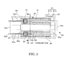
- FIG. 2 to 4 are views showing the detailed construction of the operating mechanism 3: FIG. 2 is a perspective view showing the external appearance of the operating mechanism 3; FIG. 3 is a cross-sectional view along the line A-A' along the central axis of the operating mechanism 3; and FIG. 4 is a cross-sectional view along the line B-B' orthogonal to the central axis of the operating mechanism 3.
- the operating mechanism 3 causes the output ring 34, on which is wound the three-phase coil 33, to be extended/retracted in the axial direction by excitation of the three-phase coil 33 and the magnetic field that is generated by the series of external permanent magnets 31 and the series of internal permanent magnets 32 whose magnetization energy is held approximately equal.
- this operating mechanism 3 comprises a stator 35, in addition to the output ring 34.
- the stator 35 has a cylindrical shape.
- the output ring 34 constitutes a coil support means for the three-phase coil 33 and is formed of non-magnetic material, having a shape with a pair of elongate arcuate-shaped plates 34a facing each other with their arc centers coincident, in other words, a shape in which partial facing locations of the peripheral wall of the cylinder are cut away along the axis.
- the stator 35 is fixed to the ground.
- the diameter of the output ring 34 is smaller than the diameter of the stator 35 and the output ring 34 is supported so as to be capable of axial movement within the stator 35.
- a pair of rod-shaped guide bars 36 that are longer than the stator 35 are laid along the axis of the stator 35 on the outer peripheral surface of the stator 35 and a connection member 37 is fixed to the output ring 34 by fixing of both ends of these guide bars 36 to the connection member 37.
- a guide 37a is provided on the guide bars 36, being slidably fitted onto the guide bars 36, so that the guide 37a is fixed to the stator 35.
- both ends of the stator 35 are covered by a disk 35a that is formed of non-magnetic material.
- the pair of arcuate-shaped plates 34a, 34b of the output ring 34 are linked, while maintaining the same attitude, by a disk 34c that is fixed to both ends.
- the output ring 34 is longer than the stator 35 and the disk 35a is formed with a hole through which the output ring 34 passes, matching the shape of the arcuate-shaped plates 34a, 34b.
- this operating mechanism 3 is provided with a position sensor 21 that detects the relative position of the three-phase coil 33 with respect to the series of external permanent magnets 31.
- the position sensor 21 is constituted by a linear scale 21a and an optical pickup 21b.
- the optical pickup 21b is mounted on one of the connection members 37 that moves together with the output ring 34, so that the direction of orientation of the detected and emitted light faces the side of the guide bars 36.
- the linear scale 21a is mounted along the guide bar 36, facing the optical pickup 21b.
- a three-phase coil 33 is wound on the output ring 34 as shown in FIG. 3 and 4 .
- the location of winding is recessed from the surface, but not to a depth such as to pierce this ring; the three-phase coil 33 is coplanar with or below the external peripheral surface of the output ring 34.
- the power supply lead 33a of the three-phase coil 33 passes from the disk 34c through the interior of the peripheral wall of the output ring 34.
- the series of external permanent magnets 31 and the series of internal permanent magnets 32 are arranged along the axial direction on either side of the peripheral wall of the output ring 34.
- a fixed clearance is provided between the peripheral wall of the output ring 34 and the series of external permanent magnets 31 and the series of internal permanent magnets 32.
- the internal permanent magnets 32 are of arcuate shape or ring shape and a plurality of these internal permanent magnets 32 are juxtaposed in the axial direction of an internal pipe 38, which is formed of non-magnetic material, by being fitted thereon so that their internal diameter follows the external diameter of the internal pipe 38.
- this internal pipe 38 constitutes an example of magnet fixing means for fixing the internal permanent magnets 32.
- This internal pipe 38 is coaxial with the output ring 34, being arranged at a fixed position in the interior of the output ring 34.
- the external permanent magnets 31 are arcuate-shaped or ring-shaped and a plurality of these external permanent magnets 31 are juxtaposed in the axial direction of the internal pipe 38, being stuck on so that their external diameter follows the internal diameter of an external pipe 39, which is formed of non-magnetic material.
- this external pipe 39 constitutes an example of magnet fixing means for fixing the external permanent magnets 31.
- This external pipe 39 is coaxial with the output ring 34, and the position of the output ring 34 inside the external pipe 39, they keep a certain distance each other.
- These internal permanent magnets 32 and external permanent magnets 31 are juxtaposed respectively as a Halbach array.
- the permanent magnets are adjacently arranged so as to be rotated in each case by a maximum of 90°, in a cross-section, for example the section A-A', containing the central axis of the output ring 34.
- the rotational directions of the magnetization direction are inverted in the series of internal permanent magnets 32 and the series of external permanent magnets 31.
- the direction of magnetization seen in sequence along the series of external permanent magnets 31 follows a clockwise rotation
- the direction of magnetization seen in sequence along the series of internal permanent magnets 32 follows an anticlockwise rotation, in FIG.3 .
- these internal permanent magnets 32 and external permanent magnets 31 are arranged so as to face each other in one-to-one fashion, with the peripheral wall of the output ring 34 therebetween.
- Internal permanent magnets 32 and external permanent magnets 31 having a magnetization vector with a radial component in the same direction face each other and internal permanent magnets 32 and external permanent magnets 31 having a magnetization vector with an axial component in the opposite direction face each other.
- These radial directions and axial directions are directions defined with respect to the arcuate shape or ring-shape constituted by the external permanent magnets 31 and internal permanent magnets 32.
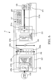
- FIG. 5 is a constructional diagram of the drive device 2.
- the drive device 2 comprises a power converter 23 and power source power converter 24 that exchange power through a bus 22. Also, a smoothing capacitor 25 and an accumulator device (battery) 26 constituting power storage means are connected with the bus 22.
- a smoothing capacitor 25 and an accumulator device (battery) 26 constituting power storage means are connected with the bus 22.
- the smoothing capacitor 25 and accumulator device 26 suppress voltage fluctuations of the bus 22 to a low level even during power consumption by the three-phase coil 33 and power regeneration from the three-phase coil 33.
- Such smoothing capacitors 25 and/or accumulator devices 26 may be suitably provided at a plurality of locations on the bus 22.
- the accumulator device 26 there are arranged a battery 26a, resistor 26b and diode 26c.
- the resistor 26b and the diode 26c are connected with the positive electrode side of the battery 26a and the resistor 26b and diode 26c are connected in parallel.
- the device in order to suppress overcharging of the battery 26a, the device is constituted so that, during power supply from the battery 26a, no power is dissipated by the resistor 26b, but, during charging of the battery 26a, part of the charging power is dissipated by the resistor 26b.
- the power converter 23 comprises a PWM (Pulse Width Modulation) inverter 23a that supplies AC current to the three-phase coil 33 through the power supply lead 33a and a thrust controller 23b that controls the PWM inverter 23a.
- the thrust controller 23b controls the PWM inverter 23a so that a thrust equal to the thrust instruction value that is input from outside the drive device 2 is generated in the three-phase coil 33.
- the PWM inverter 23a may comprise a group of power conversion elements and the thrust controller 23b may control the ignition angle of these power conversion elements.
- This thrust controller 23b is connected with at least a U phase current sensor 27 and W phase current sensor 28 and position sensor 21.
- the U phase current sensor 27 and the W phase current sensor 28 detect the exciting current of the U phase and W phase, of the U, V and W phases of the three-phase coil 33.
- the thrust controller 23b performs thrust control by referring to the signal from the U phase current sensor 27 and W phase current sensor 28 and position sensor 21.
- the power source power converter 24 comprises an inverter 24a and regenerative power receiving controller 24b.
- the regenerative power receiving controller 24b recovers power stored in the smoothing capacitor 25 and battery 26a to the power source 100, in response to a regenerative power receiving instruction signal from outside, and controls the angle of ignition of the inverter 24a in order to store the power from the power source 100.
- FIG. 6 is a constructional diagram showing the transmission mechanism 4 and the first holding mechanism 6: the left-hand half of the Figure shows the cut-off condition and the right-hand half shows the closed condition. It should be noted that, although, in this embodiment, the case is described in which the first holding mechanism 6 maintains the closed condition, it would be possible, using the same construction, for the first holding mechanism 6 to maintain a cut-off condition.
- a further intermediate rod 42 is connected between the operating rod 41 of the transmission mechanism 4 and the output ring 34.
- One end of this intermediate rod 42 and one end of the output ring 34 are rotatably journalled by means of a shared pin.
- the other end of the intermediate rod 42 and one end of the operating rod 41 are rotatably journalled by means of a shared pin.
- Journalled pin between the intermediate rod 42 and the output ring 34 is orthogonal to a journalled pin between the operating rid 41 and the intermediate rod 42.
- the first holding mechanism 6 maintains the contacting condition of the movable contact 52 and the fixed contact 53 by magnetic attraction of a target 62 such as to approach the magnet unit 61.
- This target 62 is a plate-shaped member formed of a ferromagnetic body, that is erected at the peripheral face of the intermediate rod 42.
- the intermediate rod 42 is passed through a frame 8 that is fixed to the ground; the magnet unit 61, which is constituted of a yoke 61a formed of a ferromagnetic body, and a permanent magnet 61b, is fixed in the vicinity of a hole in the frame 8, through which the intermediate rod 42 passes, so as to face the target 62.
- the magnet unit 61 is on the side of the switch mechanism 5 and the target 62 is on the side of the output ring 34. Essentially, these two items are positioned such that when the operating rod 41 moves in a direction such as to bring the movable contact 52 into contact with the fixed contact 53, the target 62 approaches the magnet unit 61. It should be noted that the same effect could be obtained even if the positional relationship of the magnet unit 61 and the target 62 is inverted.
- FIG. 7 is a constructional diagram showing the second holding mechanism 7, the upper half of the Figure showing the cut-off condition and the lower half of the Figure showing the closed condition. It should be noted that, although, in this embodiment, a description was given using an example in which the second holding mechanism 7 maintained the closed condition, it would be possible to maintain a cut-off condition using the same mechanism.
- This second holding mechanism 7 comprises a target 71 and external permanent magnets 31 and internal permanent magnets 32 that generate magnetic attractive force with respect to this target 71.
- the target 71 is a plate that is formed of a ferromagnetic body that is fixed in the output ring 34.
- This target 71 comprises an outer ring 71a and a ring 71b.
- the outer ring 71a is formed with an internal diameter such as to follow the external diameter of the output ring 34 and is erected from the outer peripheral surface of the output ring 34 by fitting therein so as to follow the outer peripheral surface of the output ring 34.
- the inner ring 71b is formed with an external diameter such as to follow the internal diameter of the output ring 34 and is erected inwards from the inner peripheral face of the output ring 34 by being stuck on so as to follow the inner peripheral surface of the outer ring 34.
- the positions of the outside ring 71a and the inside ring 71b in the length direction of the output ring 34 coincide.
- the position of the output ring 34 to which the target 71 is fixed is also maintained by the action of leakage magnetic flux of the external permanent magnets 31 and internal permanent magnets 32 on the target 71.
- the target 62 and the output ring 34 are in a fixed relationship; the output ring 34 and the movable contact 52 are in a relationship in which they are linked through the intermediate rod 42 and the operating rod 41, so the movable contact 52 is also maintained in the closed position. Consequently, in the condition in which the operating mechanism 3 is stationary, even if an external force such as weight acts on the movable contact 52, the closed condition can be maintained by magnetic force in the first holding mechanism 6 without continued actuation of the operating mechanism 3. As a result, in the first holding mechanism 6 according to the present embodiment, regardless of the mechanical system, power for maintaining the closed condition is not necessary.
- contact of the target 62 with respect to the magnet unit 61 refers to a condition in which magnetic attractive force acts to a degree such that the target 62 is fixed to the magnet unit 61 so that the position of the movable contact 52 is maintained: in other words, it also includes a condition in which these are in very close proximity albeit not strictly in contact.
- the target 71 in the closed condition of the current, the target 71 is close to or in contact with the external permanent magnets 31 and the internal permanent magnets 32. Consequently, the leakage magnetic flux of the external permanent magnets 31 and the internal permanent magnets 32 acts strongly on the target 71, preventing separating movement of the target 71 with respect to the external permanent magnets 31 and internal permanent magnets 32.
- the target 71 and the output ring 34 are in a fixed relationship; the output ring 34 and the movable contact 52 are in a relationship in which they are linked through the intermediate rod 42 and the operating rod 41, so the movable contact 52 is also maintained in the closed position. Consequently, in the condition in which the operating mechanism 3 is stationary, even if an external force such as weight acts on the movable contact 52, the closed condition can be maintained by magnetic force in the second holding mechanism 7 without continued actuation of the operating mechanism 3. As a result, in the second holding mechanism 7 according to the present embodiment, regardless of the mechanical system, power for maintaining the closed condition is not necessary.
- a thrust instruction value is input from outside the power switch 1.
- the thrust instruction value specifies the speed of movement and amount of movement of the movable contact 52.
- the power converter 23 supplies AC current to the three-phase coil 33 in accordance with the thrust instruction value, through the power supply lead 33a.
- the series of external permanent magnets 31 and the series of external permanent magnets 32 form a magnetic circuit in which the series of external permanent magnets 31 and the series of internal permanent magnets 32 are linked in a ring.
- the magnetic circuit is formed by linking the magnetic flux in the axial direction passing through the interior of the series of external permanent magnets 31 and the series of internal permanent magnets 32 and the magnetic flux in the radial direction passing through the gap between the external permanent magnets 31 and internal permanent magnets 32.
- the output ring 34 on which the three-phase coil 33 is wound, executes parallel movement between the series of external permanent magnets 31 and the series of internal permanent magnets 32.
- the detected values from the position sensor 21, U phase current sensor 27 and W phase current sensor 28 are input to the thrust controller 23b.
- the thrust controller 23b compares estimated trust value from these detected values with the thrust instruction value and controls the PWM inverter 23a so that the difference (deviation) is zero.
- the thrust controller 23b stops power supply to the three-phase coil 33 from PWM inverter 23a.
- the movable contact 52 is separated from the fixed contact 53 and current cut-off is terminated.
- a thrust instruction value that varies the velocity and/or the position of the movable contact 52 thereof is input to the thrust controller 23b, so as to suppress contact impact of the target 62 and the magnet unit 61.
- an operating mechanism 1 for performing mutual movement of a switch device between a cut-off condition and closed condition by reciprocating drive of a movable contact 52 of a power switch there are provided: a series of external permanent magnets 31, a series of internal permanent magnets 32, an internal pipe 38, an external pipe 39, a three-phase coil 33, an output ring 34 and a power supply lead 33a.
- the series of external permanent magnets 31 is constituted by juxtaposing these permanent magnets 31 in such a way that, in a cross-sectional plane containing the central axis thereof, the magnetic poles of the ring-shaped or arcuate-shaped permanent magnets are respectively rotated by, at most, 90°, in each case.
- the magnetic poles of the ring-shaped or arcuate-shaped permanent magnets have magnetization vector radial components in the same direction as the series of external permanent magnets 31 and have magnetization vector axial components in the opposite direction to the series of external permanent magnets 31.
- the internal pipe 38 and the external pipe 39 are fixed facing each other so that the series of external permanent magnets 31 and the series of internal permanent magnets 32 have the magnetization vector radial components of their respective magnetic poles in the same direction.
- the three-phase coil 33 is interposed with a fixed clearance between the series of external permanent magnets 31 and the series of internal permanent magnets 32.
- the output ring 34 has the three-phase coil 33 fixed thereto and is directly or indirectly linked with the movable contact 52: thus the output ring 34 is capable of parallel movement along the series of external permanent magnets 31 and the series of external permanent magnets 32.
- the power supply lead 33a supplies power for exciting the three-phase coil 33.
- thrust for reciprocating drive of the movable contact 52 can be generated by the action of the excited three-phase coil 33 and the magnetic circuit produced by the series of external permanent magnets 31 and the series of internal permanent magnets 32.
- the series of external permanent magnets 31 and the series of internal permanent magnets 32 hold substantially equal magnetization energies: in this way, the overwhelming majority of the magnetic flux is distributed in the radial direction in the gap between the series of external permanent magnets 31 and the series of internal permanent magnets 32. Furthermore, since the three-phase coil is arranged in the gap where the overwhelming majority of the magnetic flux is distributed in the radial direction, most of the magnetic flux links the three-phase coil 33 orthogonally, so a large thrust is generated with a smaller current. Higher-speed operation can therefore be achieved.
- the output ring 34 requires neither core nor yoke, so reduction in weight can be achieved and most of the three-phase coil 33 is linked by the main magnetic flux created by the series of internal permanent magnets 31 and internal permanent magnets 32, so the thrust/weight ratio is improved. Consequently, the response performance is also improved.
- the target 62 or the permanent magnet 61b are provided that are fixed in position, the target 62 or permanent magnet 61b being fixed to the output ring 34 or to a member that moves in linked fashion with the output ring 34, such as the intermediate rod 42: thus in relative approach of the permanent magnet 61b and the target 62 in response to movement of the output ring 34, the position of the movable contact 52 is maintained by the magnetic attractive force of the permanent magnet 61b with respect to the target 62.
- a target 71 that is fixed to the output ring 34, so leakage magnetic flux generated from the series of external permanent magnets 31 and the series of internal permanent magnets 32 acts as a magnetic attractive force on the target 71 so that the position of the movable contact 52 is maintained.
- the thrust can be adjusted so as to buffer the impact of the target 62 and the permanent magnet 61b, thereby further reducing the risk of malfunction. Also, since construction designed to reduce the risk of malfunction can be eliminated; further reduction in weight can be achieved.
- fixed operating characteristics can be realized, irrespective of the condition of wear of the movable contact 52 and/or fixed contact 53. Furthermore, by comparing the change of drive force necessary to achieve a fixed operating pattern during operation with previous data, the condition of wear of the contacts can be detected, so a diagnostic assessment of the life of the equipment can be performed. Of course, in the periodic inspection, diagnosis can also be performed under no-load operating conditions.
- FIG. 8 is an internal constructional diagram showing a power switch 1 according to a second embodiment.
- a second transmission mechanism 9 is interposed between the intermediate rod 42 and the operating rod 41.
- This second transmission mechanism 9 can be provided with the object of amplifying the thrust or amplifying the amount of movement.
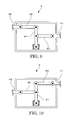
- FIG. 9 is a constructional diagram showing a second transmission mechanism 9 with the object of amplifying thrust.
- the second transmission mechanism 9 connects the intermediate rod 42 and the operating rod 41 by interposition of a plurality of links.
- the plurality of links comprise: a rod-shaped lever 91, one end of which is rotatably fixed; an auxiliary link 92 that rotatably links the intermediate rod 42 and the other end of the lever 91; and an auxiliary link 93 that rotatably links the operating rod 41 and a pivot point provided midway along the lever 91.
- FIG. 10 is a constructional diagram showing a second transmission mechanism 9 with the object of amplifying the amount of movement.
- this second transmission mechanism 9 connects the intermediate rod 42 and the operating rod 41 by interposition of a plurality of links.
- the plurality of links comprise: a rod-shaped lever 91, one end of which is rotatably fixed; an auxiliary link 92 that rotatably links the intermediate rod 42 and a pivot point provided midway along the lever 91; and an auxiliary link 93 that rotatably links the operating rod 41 and the other end of the lever 91.
- a lever 91 having a rotatable fixed point at one end and with an output ring 34 rotatably mounted directly or indirectly at the other end, and an operating rod 41 mounted at a location closer to the fixed point than that of the output ring 34.
- a lever 91 having a rotatable fixed point at one end, with an operating rod 41 rotatably mounted at the other end and an output ring 34 directly or indirectly mounted at a location that is closer to the fixed point than the location of the operating rod 41.
- FIG. 11 is a constructional diagram showing a first holding mechanism 6 of a power switch 1 according to a third embodiment.
- the left half of the Figure shows the cut-off condition and the right half of the Figure shows the closed condition.
- a frame 8 replaces the target 62.
- the frame 8 is formed of a ferromagnetic body.
- a plate-shaped rubber magnet 63 that is raised from the peripheral surface is fixed to the intermediate rod 42.
- the rubber magnet 63 and the outer ring 34 are in a fixed relationship and the outer ring 34 and the movable contact 52 are in a linked relationship, through the intermediate rod 42 and the operating rod 41, so the movable contact 52 is also maintained in the closed position. Consequently, in the condition in which the operating mechanism 3 is stationary, even if an external force such as weight acts on the movable contact 52, the operating mechanism 3 will maintain its closed condition, without continued actuation. As a result, in the first holding mechanism 6 according to the present embodiment, regardless of the mechanical system, power for maintaining the closed condition is not necessary. Furthermore, since the rubber magnet 63 provides a high resilient force, collision shock of the rubber magnet 63 and the frame 8 is buffered so that the risk of malfunction can be further reduced. Also, since construction designed to reduce the risk of malfunction can be eliminated; further reduction in weight can be achieved.
- the power switch 1 could be arranged vertically.
- the external permanent magnets and internal permanent magnets were ring-shaped, but they could be arcuate-shaped and arranged in ring shape.
Landscapes
- Physics & Mathematics (AREA)
- Electromagnetism (AREA)
- Driving Mechanisms And Operating Circuits Of Arc-Extinguishing High-Tension Switches (AREA)
- Dynamo-Electric Clutches, Dynamo-Electric Brakes (AREA)
- Linear Motors (AREA)
Abstract
Description
- An embodiment of the present invention relates to an electromagnetic drive type operating mechanism that operates a movable contact and a power switch (or sometimes also called a power switchgear) provided with this operating mechanism.
- A power switch comprises a pair of contacts and performs switching of an electrical circuit by joining or separating these contacts. When a fault current is detected, the power switch inputs a cut-off signal and, prompted by this cut-off signal, the power switch opens the contacts to cut off the current.
- Such a power switch typically comprises a pair of arc contacts and, in addition, a puffer chamber or voltage boosting chamber. The arc contacts take over the arc discharge by being separated as the circuit switching contacts are separated. The puffer chamber or voltage boosting chamber is constituted by a piston and cylinder and compresses the gas detained in the chamber by relative movement of the cylinder and piston, with the result that high-pressure gas from inside and outside the chamber is injected between the contacts. The arc discharge is extinguished by this injection of high-pressure gas, completing current cut-off.
- The operating mechanism is provided in order to perform respective relative movement of the movable contacts for switching this electrical circuit, the arc movable contacts, and the piston or cylinder. It is therefore desirable that this operating mechanism should be capable of being driven in a manner that can be freely selected, should be capable of high-speed movement of the movable elements thereof, and should have excellent response of the movable elements thereof.
- The reason why the operating mechanism should be capable of being driven in a manner that can be freely selected is that, since the fault current is AC and its voltage fluctuates cyclically, and the phase at which the fault occurs is random, it is desirable that the cut-off operation should be performed with suitable timing to facilitate cut-off, taking into account the state transition involved in arc extinction after generation of a fault current.
- The reason why the operating mechanism should be capable of high-speed movement and should have excellent response of the movable elements thereof is that the cut-off action must be completed in the short time of a few tens of msec from start of the cut-off instruction.
- Furthermore, in addition to these aspects concerning drive performance, because of progress which has been made with regard to underground installation of power equipment and the provision of a drive mechanism, restricted size of the operating mechanism and ease of maintenance are being demanded.
- Types of operating mechanism that have currently been proposed include the air type, hydraulic type, spring type or electromagnetic drive type. The hydraulic type is a type in which a movable element is driven using a hydraulic actuator. The spring type is a type in which the movable element is driven using the energy obtained when a spring is released: this is the type which is currently chiefly employed. The electromagnetic drive type is a type in which the movable element is driven by an electromagnetic actuator.
- Of these, an example of the electromagnetic drive type is the type in which the movable contact is driven by converting the motive power of a rotary electrical machine to linear motion: examples are Laid-open Japanese Patent Application Number
Tokkai 2009-212372 Tokkai 2008-021599 - Also, there may be mentioned, as examples of the use of electromagnetic attractive force or electromagnetic repulsion force as direct thrust, a system in which the attractive force of an electromagnet and permanent magnet is employed. An example is: Laid-open Japanese Patent Application Number
Tokkai 2003-016888 Tokkai H 10-040782 Tokkai 2002-124158 Tokkai 11-025817 - A method of driving such an air-cored coil has also been proposed, in which cylindrical permanent magnets are employed that are arranged internally and externally, maintaining a mutually fixed separation, and an exciting current is applied to an air-cored coil located between these internal and external cylindrical permanent magnets. An example is issued Japanese Patent Number
4625032 - Various types of such electromagnetic drive-type operating mechanisms have been proposed, but it has been remarked that they are inferior in regard to thrust, which is indispensable for high-speed closure of the movable contacts and high-speed cut-off, compared with hydraulic-type operating mechanisms or spring-type operating mechanisms.
- Specifically, although, in the example employing a rotary motor illustrated in
Patent References - Also, in the systems in which electromagnetic attraction or electromagnetic repulsion is directly employed as thrust as in
Patent References 3 to 2, it is difficult to achieve a fully selectable level of drive in all operating regions, so it is difficult to perform cut-off operation with the appropriate timing to facilitate cut-off. - In the system using an actuator in which cylindrical permanent magnets are arranged as shown in
Patent Reference 7, a fully selectable level of drive can be achieved and, since no core is employed in the coil, the inductance can be kept at a comparatively low level. However, even though a core is not employed in the interior of the coil, magnetic rings are arranged at both ends of the ring-shaped coil, so an appreciable increase in inductance may be caused. - Also, since the direction of magnetization of both the internal and external cylindrical permanent magnets is uniformly in the same radial direction, the magnetic flux generated from the internal and external cylindrical permanent magnets follows a path from the outside face of the external cylindrical permanent magnet, through the lower bottom and upper bottom of the cylinder, passing through the inside face of the internal cylinder, and returning again to the external cylindrical permanent magnet. In order to make the flow of this magnetic flux smooth and create a more powerful magnetic flux, and in order to avoid the external effects of the magnetic field, a back yoke must be employed comprising a cylindrical-shaped magnetic body, outside the external cylindrical permanent magnet and inside the internal cylindrical permanent magnets.
- In this case, an internal back yoke of course has the same effect as a core in relation to the coil, and an external back yoke also has the same effect. There is therefore the problem that the inductance of the coil becomes large.
- In addition, a powerful permanent magnet must be used in order to increase the thrust and the back yoke must be made thick in order to avoid magnetic saturation of the back yoke. For this reason, even if a powerful permanent magnet is employed, it is difficult to reduce the volume/thrust ratio.
- In other words, even in the case of the proposed system of
Patent Reference 7, it was not possible to satisfy requirements with respect to response and/or thrust. - As stated above, with an electromagnetic drive type operating mechanism, albeit the required indispensable functionality was provided, it was difficult to satisfy requirements with respect to high speed and fast response. The present invention was made in order to solve this problem, its object being to provide a power switch operating mechanism and power switch provided therewith of high speed and fast response, having the necessary indispensable functionality.
- In order to achieve the above object, the present invention is constructed as follows. Specifically, a power switch operating mechanism for moving a switch device between a cut-off condition and a closed condition by reciprocating drive of a movable contact comprises: a series of first permanent magnets; a series of second permanent magnets; magnet fixing means; a coil; coil support means; and a power supply lead.
- In addition, this first permanent magnet series is configured so that these permanent magnets are juxtaposed in such a way that the magnetic poles of ring-shaped or arcuate-shaped permanent magnets are rotated by a maximum of 90° in each case in the cross-section including the central axis thereof. The second permanent magnet series is configured so that the magnetic poles of ring-shaped or arcuate-shaped permanent magnets have a magnetization vector radial component in the same direction as the series of the first permanent magnets or have a magnetization vector axial component in the opposite direction to that of the series of the first permanent magnets. The magnet fixing means fixes the series of the first permanent magnets and the series of the second permanent magnets so that the magnetization vector radial components of their respective magnetic poles face in the same direction. The coil is interposed between the first permanent magnet series and the second permanent magnet series with a fixed clearance. The coil support means is directly or indirectly linked with the movable contact so that the coil is fixed and is capable of parallel movement along the series of the first and second permanent magnets. The power supply lead supplies power for exciting the coil.
- In this way, the thrust for reciprocating drive of the movable contact is generated by the action of the excited coil and the magnetic circuit generated by the first permanent magnet series and the second permanent magnet series.
-
-
FIG. 1 is an internal constructional diagram showing a power switch according to a first embodiment; -
FIG. 2 is a perspective view showing an external view of an operating mechanism; -
FIG. 3 is a cross-sectional view along the axis of the operating mechanism; -
FIG. 4 is a cross-sectional view orthogonal to the axis of the operating mechanism; -
FIG. 5 is a constructional diagram of a drive device; -
FIG. 6 is a constructional diagram showing a transmission mechanism and a first holding mechanism; -
FIG. 7 is a constructional diagram showing a second holding mechanism; -
FIG. 8 is an internal constructional diagram showing a power switch according to a second embodiment; -
FIG. 9 is a constructional diagram showing an example construction of a second transmission mechanism; -
FIG. 10 is a constructional diagram showing another example construction of a second transmission mechanism; and -
FIG. 11 is a constructional diagram showing a first holding mechanism according to a third embodiment. -
FIG. 1 is an internal constructional diagram showing a power switch according to a first embodiment. Thepower switch 1 is a device for opening/closing an electrical circuit and comprises: adrive device 2; an operating mechanism having atransmission mechanism 4, afirst holding mechanism 6, asecond holding mechanism 7; and aswitch mechanism 5. - The
drive device 2 drives theoperating mechanism 3 by supplying the power delivered from thepower source 100 to theoperating mechanism 3. Theoperating mechanism 3 is an operating mechanism that generates thrust in a linear direction (an axial direction). Thetransmission mechanism 4 has an operatingrod 41 that is movable in the axial direction and thrust generated by theoperating mechanism 3 is transmitted to theswitch mechanism 5 by pushing/pulling this operatingrod 41. - In the
switch mechanism 5, amovable contact 52 and a fixedcontact 53 are arranged within a sealedspace 51 that is filled with arc-extinguishing gas; also themovable contact 52 is fixed to the operatingrod 41 and themovable contact 52 can be brought into contact with or separated from the fixedcontact 53 in response to pushing/pulling the operatingrod 41. Thefirst holding mechanism 6 and thesecond holding mechanism 7 maintain a contact condition of themovable contact 52 and the fixedcontact 53 during the current-connected condition, in which thrust has not been generated by theoperating mechanism 3. -
FIG. 2 to 4 are views showing the detailed construction of the operating mechanism 3:FIG. 2 is a perspective view showing the external appearance of theoperating mechanism 3;FIG. 3 is a cross-sectional view along the line A-A' along the central axis of theoperating mechanism 3; andFIG. 4 is a cross-sectional view along the line B-B' orthogonal to the central axis of theoperating mechanism 3. As shown inFIG. 2 to FIG. 4 , theoperating mechanism 3 causes theoutput ring 34, on which is wound the three-phase coil 33, to be extended/retracted in the axial direction by excitation of the three-phase coil 33 and the magnetic field that is generated by the series of externalpermanent magnets 31 and the series of internalpermanent magnets 32 whose magnetization energy is held approximately equal. - As shown in
FIG. 2 , basically, thisoperating mechanism 3 comprises astator 35, in addition to theoutput ring 34. Thestator 35 has a cylindrical shape. Theoutput ring 34 constitutes a coil support means for the three-phase coil 33 and is formed of non-magnetic material, having a shape with a pair of elongate arcuate-shapedplates 34a facing each other with their arc centers coincident, in other words, a shape in which partial facing locations of the peripheral wall of the cylinder are cut away along the axis. - The
stator 35 is fixed to the ground. The diameter of theoutput ring 34 is smaller than the diameter of thestator 35 and theoutput ring 34 is supported so as to be capable of axial movement within thestator 35. Specifically, a pair of rod-shaped guide bars 36 that are longer than thestator 35 are laid along the axis of thestator 35 on the outer peripheral surface of thestator 35 and aconnection member 37 is fixed to theoutput ring 34 by fixing of both ends of these guide bars 36 to theconnection member 37. In addition, a guide 37a is provided on the guide bars 36, being slidably fitted onto the guide bars 36, so that the guide 37a is fixed to thestator 35. - It should be noted that both ends of the
stator 35 are covered by adisk 35a that is formed of non-magnetic material. Also, the pair of arcuate-shapedplates output ring 34 are linked, while maintaining the same attitude, by adisk 34c that is fixed to both ends. Furthermore, theoutput ring 34 is longer than thestator 35 and thedisk 35a is formed with a hole through which theoutput ring 34 passes, matching the shape of the arcuate-shapedplates - Also, this
operating mechanism 3 is provided with aposition sensor 21 that detects the relative position of the three-phase coil 33 with respect to the series of externalpermanent magnets 31. Theposition sensor 21 is constituted by alinear scale 21a and anoptical pickup 21b. Theoptical pickup 21b is mounted on one of theconnection members 37 that moves together with theoutput ring 34, so that the direction of orientation of the detected and emitted light faces the side of the guide bars 36. Thelinear scale 21a is mounted along theguide bar 36, facing theoptical pickup 21b. - Within this
operating mechanism 3, a three-phase coil 33 is wound on theoutput ring 34 as shown inFIG. 3 and4 . The location of winding is recessed from the surface, but not to a depth such as to pierce this ring; the three-phase coil 33 is coplanar with or below the external peripheral surface of theoutput ring 34. Thepower supply lead 33a of the three-phase coil 33 passes from thedisk 34c through the interior of the peripheral wall of theoutput ring 34. - The series of external
permanent magnets 31 and the series of internalpermanent magnets 32 are arranged along the axial direction on either side of the peripheral wall of theoutput ring 34. A fixed clearance is provided between the peripheral wall of theoutput ring 34 and the series of externalpermanent magnets 31 and the series of internalpermanent magnets 32. - The internal
permanent magnets 32 are of arcuate shape or ring shape and a plurality of these internalpermanent magnets 32 are juxtaposed in the axial direction of aninternal pipe 38, which is formed of non-magnetic material, by being fitted thereon so that their internal diameter follows the external diameter of theinternal pipe 38. Thus thisinternal pipe 38 constitutes an example of magnet fixing means for fixing the internalpermanent magnets 32. Thisinternal pipe 38 is coaxial with theoutput ring 34, being arranged at a fixed position in the interior of theoutput ring 34. - The external
permanent magnets 31 are arcuate-shaped or ring-shaped and a plurality of these externalpermanent magnets 31 are juxtaposed in the axial direction of theinternal pipe 38, being stuck on so that their external diameter follows the internal diameter of anexternal pipe 39, which is formed of non-magnetic material. Thus thisexternal pipe 39 constitutes an example of magnet fixing means for fixing the externalpermanent magnets 31. Thisexternal pipe 39 is coaxial with theoutput ring 34, and the position of theoutput ring 34 inside theexternal pipe 39, they keep a certain distance each other. - These internal
permanent magnets 32 and externalpermanent magnets 31 are juxtaposed respectively as a Halbach array. In this embodiment, the permanent magnets are adjacently arranged so as to be rotated in each case by a maximum of 90°, in a cross-section, for example the section A-A', containing the central axis of theoutput ring 34. - Also, the rotational directions of the magnetization direction are inverted in the series of internal
permanent magnets 32 and the series of externalpermanent magnets 31. In other words, for example, the direction of magnetization seen in sequence along the series of externalpermanent magnets 31 follows a clockwise rotation, whereas the direction of magnetization seen in sequence along the series of internalpermanent magnets 32 follows an anticlockwise rotation, inFIG.3 . - In addition, these internal
permanent magnets 32 and externalpermanent magnets 31 are arranged so as to face each other in one-to-one fashion, with the peripheral wall of theoutput ring 34 therebetween. Internalpermanent magnets 32 and externalpermanent magnets 31 having a magnetization vector with a radial component in the same direction face each other and internalpermanent magnets 32 and externalpermanent magnets 31 having a magnetization vector with an axial component in the opposite direction face each other. These radial directions and axial directions are directions defined with respect to the arcuate shape or ring-shape constituted by the externalpermanent magnets 31 and internalpermanent magnets 32. -
FIG. 5 is a constructional diagram of thedrive device 2. Thedrive device 2 comprises apower converter 23 and powersource power converter 24 that exchange power through abus 22. Also, a smoothingcapacitor 25 and an accumulator device (battery) 26 constituting power storage means are connected with thebus 22. - The smoothing
capacitor 25 andaccumulator device 26 suppress voltage fluctuations of thebus 22 to a low level even during power consumption by the three-phase coil 33 and power regeneration from the three-phase coil 33. Such smoothingcapacitors 25 and/oraccumulator devices 26 may be suitably provided at a plurality of locations on thebus 22. - Also, in the
accumulator device 26, there are arranged abattery 26a,resistor 26b anddiode 26c. Theresistor 26b and thediode 26c are connected with the positive electrode side of thebattery 26a and theresistor 26b anddiode 26c are connected in parallel. In more detail, in order to suppress overcharging of thebattery 26a, the device is constituted so that, during power supply from thebattery 26a, no power is dissipated by theresistor 26b, but, during charging of thebattery 26a, part of the charging power is dissipated by theresistor 26b. - The
power converter 23 comprises a PWM (Pulse Width Modulation)inverter 23a that supplies AC current to the three-phase coil 33 through thepower supply lead 33a and athrust controller 23b that controls thePWM inverter 23a. Thethrust controller 23b controls thePWM inverter 23a so that a thrust equal to the thrust instruction value that is input from outside thedrive device 2 is generated in the three-phase coil 33. For example, thePWM inverter 23a may comprise a group of power conversion elements and thethrust controller 23b may control the ignition angle of these power conversion elements. - This
thrust controller 23b is connected with at least a U phasecurrent sensor 27 and W phasecurrent sensor 28 andposition sensor 21. The U phasecurrent sensor 27 and the W phasecurrent sensor 28 detect the exciting current of the U phase and W phase, of the U, V and W phases of the three-phase coil 33. Thethrust controller 23b performs thrust control by referring to the signal from the U phasecurrent sensor 27 and W phasecurrent sensor 28 andposition sensor 21. - The power
source power converter 24 comprises aninverter 24a and regenerativepower receiving controller 24b. The regenerativepower receiving controller 24b recovers power stored in the smoothingcapacitor 25 andbattery 26a to thepower source 100, in response to a regenerative power receiving instruction signal from outside, and controls the angle of ignition of theinverter 24a in order to store the power from thepower source 100. -
FIG. 6 is a constructional diagram showing thetransmission mechanism 4 and the first holding mechanism 6: the left-hand half of the Figure shows the cut-off condition and the right-hand half shows the closed condition. It should be noted that, although, in this embodiment, the case is described in which thefirst holding mechanism 6 maintains the closed condition, it would be possible, using the same construction, for thefirst holding mechanism 6 to maintain a cut-off condition. - A further
intermediate rod 42 is connected between the operatingrod 41 of thetransmission mechanism 4 and theoutput ring 34. One end of thisintermediate rod 42 and one end of theoutput ring 34 are rotatably journalled by means of a shared pin. Also, the other end of theintermediate rod 42 and one end of the operatingrod 41 are rotatably journalled by means of a shared pin. Journalled pin between theintermediate rod 42 and theoutput ring 34 is orthogonal to a journalled pin between the operating rid 41 and theintermediate rod 42. - Next, with movement of the operating
rod 41 provided in thetransmission mechanism 4, thefirst holding mechanism 6 maintains the contacting condition of themovable contact 52 and the fixedcontact 53 by magnetic attraction of atarget 62 such as to approach themagnet unit 61. - This
target 62 is a plate-shaped member formed of a ferromagnetic body, that is erected at the peripheral face of the
intermediate rod 42. Theintermediate rod 42 is passed through aframe 8 that is fixed to the ground; themagnet unit 61, which is constituted of ayoke 61a formed of a ferromagnetic body, and apermanent magnet 61b, is fixed in the vicinity of a hole in theframe 8, through which theintermediate rod 42 passes, so as to face thetarget 62. - Regarding the positional relationship of the
magnet unit 61 and thetarget 62, themagnet unit 61 is on the side of theswitch mechanism 5 and thetarget 62 is on the side of theoutput ring 34. Essentially, these two items are positioned such that when the operatingrod 41 moves in a direction such as to bring themovable contact 52 into contact with the fixedcontact 53, thetarget 62 approaches themagnet unit 61. It should be noted that the same effect could be obtained even if the positional relationship of themagnet unit 61 and thetarget 62 is inverted. -
FIG. 7 is a constructional diagram showing thesecond holding mechanism 7, the upper half of the Figure showing the cut-off condition and the lower half of the Figure showing the closed condition. It should be noted that, although, in this embodiment, a description was given using an example in which thesecond holding mechanism 7 maintained the closed condition, it would be possible to maintain a cut-off condition using the same mechanism. Thissecond holding mechanism 7 comprises atarget 71 and externalpermanent magnets 31 and internalpermanent magnets 32 that generate magnetic attractive force with respect to thistarget 71. - The
target 71 is a plate that is formed of a ferromagnetic body that is fixed in theoutput ring 34. Thistarget 71 comprises anouter ring 71a and aring 71b. Theouter ring 71a is formed with an internal diameter such as to follow the external diameter of theoutput ring 34 and is erected from the outer peripheral surface of theoutput ring 34 by fitting therein so as to follow the outer peripheral surface of theoutput ring 34. Theinner ring 71b is formed with an external diameter such as to follow the internal diameter of theoutput ring 34 and is erected inwards from the inner peripheral face of theoutput ring 34 by being stuck on so as to follow the inner peripheral surface of theouter ring 34. The positions of theoutside ring 71a and theinside ring 71b in the length direction of theoutput ring 34 coincide. - In the closed condition, the position of the
output ring 34 to which thetarget 71 is fixed is also maintained by the action of leakage magnetic flux of the externalpermanent magnets 31 and internalpermanent magnets 32 on thetarget 71. - The operation and action of a
power switch 1 constructed as above will now be described. When theoperating mechanism 3 is in a stationary condition, no thrust at all is output to themovable contact 52 of theswitch mechanism 5. In this condition, themovable contact 52 is moved towards the fixedcontact 53 and themovable contact 52 and fixedcontact 53 are thus in contact. - In this closed condition of the current, as shown in the right-hand half of
FIG. 6 , thetarget 62 is in contact with themagnet unit 61. Consequently, the magnetic attractive force of themagnet unit 61 acts strongly on thetarget 62, with the result that thetarget 62 is fixed to themagnet unit 61. - The
target 62 and theoutput ring 34 are in a fixed relationship; theoutput ring 34 and themovable contact 52 are in a relationship in which they are linked through theintermediate rod 42 and the operatingrod 41, so themovable contact 52 is also maintained in the closed position. Consequently, in the condition in which theoperating mechanism 3 is stationary, even if an external force such as weight acts on themovable contact 52, the closed condition can be maintained by magnetic force in thefirst holding mechanism 6 without continued actuation of theoperating mechanism 3. As a result, in thefirst holding mechanism 6 according to the present embodiment, regardless of the mechanical system, power for maintaining the closed condition is not necessary. - It should be noted that contact of the
target 62 with respect to themagnet unit 61 refers to a condition in which magnetic attractive force acts to a degree such that thetarget 62 is fixed to themagnet unit 61 so that the position of themovable contact 52 is maintained: in other words, it also includes a condition in which these are in very close proximity albeit not strictly in contact. - Also, as shown in the bottom half of
FIG. 7 , in the closed condition of the current, thetarget 71 is close to or in contact with the externalpermanent magnets 31 and the internalpermanent magnets 32. Consequently, the leakage magnetic flux of the externalpermanent magnets 31 and the internalpermanent magnets 32 acts strongly on thetarget 71, preventing separating movement of thetarget 71 with respect to the externalpermanent magnets 31 and internalpermanent magnets 32. - The
target 71 and theoutput ring 34 are in a fixed relationship; theoutput ring 34 and themovable contact 52 are in a relationship in which they are linked through theintermediate rod 42 and the operatingrod 41, so themovable contact 52 is also maintained in the closed position. Consequently, in the condition in which theoperating mechanism 3 is stationary, even if an external force such as weight acts on themovable contact 52, the closed condition can be maintained by magnetic force in thesecond holding mechanism 7 without continued actuation of theoperating mechanism 3. As a result, in thesecond holding mechanism 7 according to the present embodiment, regardless of the mechanical system, power for maintaining the closed condition is not necessary. - Next, if a fault current is generated in the system, a thrust instruction value is input from outside the
power switch 1. The thrust instruction value specifies the speed of movement and amount of movement of themovable contact 52. Thepower converter 23 supplies AC current to the three-phase coil 33 in accordance with the thrust instruction value, through thepower supply lead 33a. - Whereas AC current flows in the three-
phase coil 33, as shown inFIG. 3 , the series of externalpermanent magnets 31 and the series of externalpermanent magnets 32 form a magnetic circuit in which the series of externalpermanent magnets 31 and the series of internalpermanent magnets 32 are linked in a ring. - More specifically, the magnetic circuit is formed by linking the magnetic flux in the axial direction passing through the interior of the series of external
permanent magnets 31 and the series of internalpermanent magnets 32 and the magnetic flux in the radial direction passing through the gap between the externalpermanent magnets 31 and internalpermanent magnets 32. Thus scarcely any of the magnetic flux from the series of externalpermanent magnets 31 appears at the outside face of the series of externalpermanent magnets 31 and scarcely any of the magnetic flux of the series of internalpermanent magnets 32 appears at the inside face of the series of internalpermanent magnets 32. Consequently, the overwhelming majority of the magnetic flux in the radial direction is distributed in the gap between the externalpermanent magnets 31 and internalpermanent magnets 32 i.e. most of the magnetic flux in the radial direction is orthogonally linked with the excited three-phase coil 33. Consequently, theoutput ring 34, on which the three-phase coil 33 is wound, executes parallel movement between the series of externalpermanent magnets 31 and the series of internalpermanent magnets 32. - When movement of the
output ring 34 takes place, the detected values from theposition sensor 21, U phasecurrent sensor 27 and W phasecurrent sensor 28 are input to thethrust controller 23b. Thethrust controller 23b compares estimated trust value from these detected values with the thrust instruction value and controls thePWM inverter 23a so that the difference (deviation) is zero. - Then, when the detected value obtained by the
position sensor 21 reaches the desired value, thethrust controller 23b stops power supply to the three-phase coil 33 fromPWM inverter 23a. Whereat, in theswitch mechanism 5, themovable contact 52 is separated from the fixedcontact 53 and current cut-off is terminated. In this process, preferably a thrust instruction value that varies the velocity and/or the position of themovable contact 52 thereof is input to thethrust controller 23b, so as to suppress contact impact of thetarget 62 and themagnet unit 61. - Operation in the case of closure of the
power switch 1 is the same as in the case of this cut-off operation: when a closure instruction is input to thepower switch 1, AC current is applied to the three-phase coil 33, and the closure operation is performed in the same way as the cut-off operation, in the opposite direction to the direction of the cut-off operation, so as to connect themovable contact 52 and the fixedcontact 53. - As described above, in an
operating mechanism 1 for performing mutual movement of a switch device between a cut-off condition and closed condition by reciprocating drive of amovable contact 52 of apower switch 1, in this embodiment, there are provided: a series of externalpermanent magnets 31, a series of internalpermanent magnets 32, aninternal pipe 38, anexternal pipe 39, a three-phase coil 33, anoutput ring 34 and apower supply lead 33a. - The series of external
permanent magnets 31 is constituted by juxtaposing thesepermanent magnets 31 in such a way that, in a cross-sectional plane containing the central axis thereof, the magnetic poles of the ring-shaped or arcuate-shaped permanent magnets are respectively rotated by, at most, 90°, in each case. In the series of internalpermanent magnets 32, the magnetic poles of the ring-shaped or arcuate-shaped permanent magnets have magnetization vector radial components in the same direction as the series of externalpermanent magnets 31 and have magnetization vector axial components in the opposite direction to the series of externalpermanent magnets 31. - The
internal pipe 38 and theexternal pipe 39 are fixed facing each other so that the series of externalpermanent magnets 31 and the series of internalpermanent magnets 32 have the magnetization vector radial components of their respective magnetic poles in the same direction. The three-phase coil 33 is interposed with a fixed clearance between the series of externalpermanent magnets 31 and the series of internalpermanent magnets 32. Theoutput ring 34 has the three-phase coil 33 fixed thereto and is directly or indirectly linked with the movable contact 52: thus theoutput ring 34 is capable of parallel movement along the series of externalpermanent magnets 31 and the series of externalpermanent magnets 32. Thepower supply lead 33a supplies power for exciting the three-phase coil 33. - In this way, thrust for reciprocating drive of the
movable contact 52 can be generated by the action of the excited three-phase coil 33 and the magnetic circuit produced by the series of externalpermanent magnets 31 and the series of internalpermanent magnets 32. - In this process, scarcely any magnetic flux issues from the outside face of the series of external
permanent magnets 31 and the inside face of the series of internalpermanent magnets 32, so substantially almost of the magnetic flux goes to constitute the magnetic circuit between the outside face of the series of externalpermanent magnets 31 and the inside face of the series of internalpermanent magnets 32. Consequently, a back yoke is unnecessary. - In addition, the series of external
permanent magnets 31 and the series of internalpermanent magnets 32 hold substantially equal magnetization energies: in this way, the overwhelming majority of the magnetic flux is distributed in the radial direction in the gap between the series of externalpermanent magnets 31 and the series of internalpermanent magnets 32. Furthermore, since the three-phase coil is arranged in the gap where the overwhelming majority of the magnetic flux is distributed in the radial direction, most of the magnetic flux links the three-phase coil 33 orthogonally, so a large thrust is generated with a smaller current. Higher-speed operation can therefore be achieved. - Also, when the
operating mechanism 3 is in an operating condition, neither core nor yoke is present in the vicinity of the three-phase coil 33 or the main magnetic flux created by the series of externalpermanent magnets 31 and the series of internalpermanent magnets 32, so the three-phase coil 33 has little self-inductance. Consequently, even if theoutput ring 34 is operated at high speed, the voltage required for passage of the required exciting current to the three-phase coil 33 is reduced. - Also, the
output ring 34 requires neither core nor yoke, so reduction in weight can be achieved and most of the three-phase coil 33 is linked by the main magnetic flux created by the series of internalpermanent magnets 31 and internalpermanent magnets 32, so the thrust/weight ratio is improved. Consequently, the response performance is also improved. - Furthermore, the
target 62 or thepermanent magnet 61b are provided that are fixed in position, thetarget 62 orpermanent magnet 61b being fixed to theoutput ring 34 or to a member that moves in linked fashion with theoutput ring 34, such as the intermediate rod 42: thus in relative approach of thepermanent magnet 61b and thetarget 62 in response to movement of theoutput ring 34, the position of themovable contact 52 is maintained by the magnetic attractive force of thepermanent magnet 61b with respect to thetarget 62. - Also, there is further provided a
target 71 that is fixed to theoutput ring 34, so leakage magnetic flux generated from the series of externalpermanent magnets 31 and the series of internalpermanent magnets 32 acts as a magnetic attractive force on thetarget 71 so that the position of themovable contact 52 is maintained. - In this way a mechanical holding mechanism can be dispensed with: this contributes to weight reduction of the device. Consequently the thrust/weight ratio is further improved and response performance is further improved. Furthermore, the fact that no mechanical holding mechanism including such a sliding portion is provided and the fact that power for maintaining the closed condition or the cut-off condition is unnecessary are beneficial in that these therefore do not interfere with giving priority to the electromagnetic drive type operating mechanism in terms of maintenance.
- Furthermore, since any desired manner of drive of the operating mechanism of this embodiment can be employed, the thrust can be adjusted so as to buffer the impact of the
target 62 and thepermanent magnet 61b, thereby further reducing the risk of malfunction. Also, since construction designed to reduce the risk of malfunction can be eliminated; further reduction in weight can be achieved. - Also, fixed operating characteristics can be realized, irrespective of the condition of wear of the
movable contact 52 and/or fixedcontact 53. Furthermore, by comparing the change of drive force necessary to achieve a fixed operating pattern during operation with previous data, the condition of wear of the contacts can be detected, so a diagnostic assessment of the life of the equipment can be performed. Of course, in the periodic inspection, diagnosis can also be performed under no-load operating conditions. -
FIG. 8 is an internal constructional diagram showing apower switch 1 according to a second embodiment. As shown inFIG. 8 , in thispower switch 1, asecond transmission mechanism 9 is interposed between theintermediate rod 42 and the operatingrod 41. Thissecond transmission mechanism 9 can be provided with the object of amplifying the thrust or amplifying the amount of movement. -
FIG. 9 is a constructional diagram showing asecond transmission mechanism 9 with the object of amplifying thrust. As shown inFIG. 9 , thesecond transmission mechanism 9 connects theintermediate rod 42 and the operatingrod 41 by interposition of a plurality of links. The plurality of links comprise: a rod-shapedlever 91, one end of which is rotatably fixed; anauxiliary link 92 that rotatably links theintermediate rod 42 and the other end of thelever 91; and anauxiliary link 93 that rotatably links the operatingrod 41 and a pivot point provided midway along thelever 91. -
FIG. 10 is a constructional diagram showing asecond transmission mechanism 9 with the object of amplifying the amount of movement. As shown inFIG, 10 , thissecond transmission mechanism 9 connects theintermediate rod 42 and the operatingrod 41 by interposition of a plurality of links. The plurality of links comprise: a rod-shapedlever 91, one end of which is rotatably fixed; anauxiliary link 92 that rotatably links theintermediate rod 42 and a pivot point provided midway along thelever 91; and anauxiliary link 93 that rotatably links the operatingrod 41 and the other end of thelever 91. - Thus, there is provided a
lever 91 having a rotatable fixed point at one end and with anoutput ring 34 rotatably mounted directly or indirectly at the other end, and an operatingrod 41 mounted at a location closer to the fixed point than that of theoutput ring 34. - In the case of this
second transmission mechanism 9, the distance of the action point with respect to the pivot point (fulcrum point) is closer than in the case of the application point. Consequently, when thelever 91 acts as a lever, the moving force of theintermediate rod 42 is amplified when it is transmitted to the operatingrod 41. - Also, there is provided a
lever 91 having a rotatable fixed point at one end, with an operatingrod 41 rotatably mounted at the other end and anoutput ring 34 directly or indirectly mounted at a location that is closer to the fixed point than the location of the operatingrod 41. - In the case of this
second transmission mechanism 9, the distance of the application point with respect to the pivot point is closer than in the case of the action point. Consequently, when thelever 91 acts as a lever, the amount of movement of theintermediate rod 42 is amplified when it is transmitted to the operatingrod 41. - Also, although the number of components or sliding portions is increased, since the function is provided of achieving increase/decrease of the thrust or stroke, the benefit is obtained that the degrees of design freedom with respect to the
operating mechanism 3 orswitch device 5 are increased. -
FIG. 11 is a constructional diagram showing afirst holding mechanism 6 of apower switch 1 according to a third embodiment. The left half of the Figure shows the cut-off condition and the right half of the Figure shows the closed condition. As shown inFIG. 11 , in thisfirst holding mechanism 6, aframe 8 replaces thetarget 62. Specifically, theframe 8 is formed of a ferromagnetic body. Furthermore, a plate-shapedrubber magnet 63 that is raised from the peripheral surface is fixed to theintermediate rod 42. - With this
first holding mechanism 6, as shown in the right-hand part ofFIG. 11 , therubber magnet 63 is in contact with theframe 8. The strong magnetic attractive force of therubber magnet 63 therefore acts on theframe 8, fixing therubber magnet 63 to theframe 8. - The
rubber magnet 63 and theouter ring 34 are in a fixed relationship and theouter ring 34 and themovable contact 52 are in a linked relationship, through theintermediate rod 42 and the operatingrod 41, so themovable contact 52 is also maintained in the closed position. Consequently, in the condition in which theoperating mechanism 3 is stationary, even if an external force such as weight acts on themovable contact 52, theoperating mechanism 3 will maintain its closed condition, without continued actuation. As a result, in thefirst holding mechanism 6 according to the present embodiment, regardless of the mechanical system, power for maintaining the closed condition is not necessary. Furthermore, since therubber magnet 63 provides a high resilient force, collision shock of therubber magnet 63 and theframe 8 is buffered so that the risk of malfunction can be further reduced. Also, since construction designed to reduce the risk of malfunction can be eliminated; further reduction in weight can be achieved. - While various embodiments of the present invention have been described above, these embodiments are presented merely by way of example and are not intended to restrict the scope of the invention. Specifically, combinations of all or some of the first to the third embodiments are included. The above embodiments can be put into practice in various other forms and various deletions or substitutions or modifications may be effected in a range not departing from the scope of the invention. Such embodiments or modifications thereof are included in the scope or gist of the invention and, likewise, are included in the invention as set out in the scope of the patent claims and equivalents thereof.
- For example, whereas in the Figures examples were shown in which the
power switch 1 is horizontal, thepower switch 1 could be arranged vertically. Also, examples were described in which the external permanent magnets and internal permanent magnets were ring-shaped, but they could be arcuate-shaped and arranged in ring shape.
Claims (10)
- A power switch operating mechanism for moving a switch device between a cut-off condition and a closed condition by reciprocating drive of a movable contact, said power switch operating mechanism comprising:a series of first permanent magnets constituted by arranging these permanent ring-shaped or arcuate-shaped magnets adjacently wherein magnetic poles of these permanent magnets are rotated by a maximum of 90° in each case in a cross-section including a central axis thereof;a series of second permanent magnets wherein magnetic poles of these ring-shaped or arcuate-shaped permanent magnets have a magnetization vector radial component in a same direction as said series of first permanent magnets or have a magnetization vector axial component in an opposite direction to that of said series of first permanent magnets;a magnet fixing means for fixing said series of first permanent magnets and said series of second permanent magnets so that magnetization vector radial components of their respective magnetic poles face in a same direction;a coil that is interposed between said series of first permanent magnets and said second series of permanent magnets with a fixed clearance;a coil support means for being directly or indirectly linked with said movable contact so that said coil is fixed and is capable of parallel movement along said series of first and second permanent magnets; anda power supply lead that supplies power for exciting said coil,whereby thrust for reciprocating drive of said movable contact is generated by an action of said excited coil and a magnetic circuit generated by said series of first permanent magnets and said series of second permanent magnets.
- The power switch operating mechanism according to claim 1, wherein first permanent magnets and second permanent magnets hold equivalent magnetic energy.
- The power switch operating mechanism according to claim 1 or 2, further comprising:a ferromagnetic body that is fixed to said coil support means or a member that moves linked with said coil support means; anda third permanent magnet whose position is fixed;wherein a position of said movable contact is maintained by a magnetic attractive force of said third permanent magnet with respect to said ferromagnetic body, by relative approach of said ferromagnetic body and said third permanent magnet in response to movement of said coil support means.
- The power switch operating mechanism according to claim 1 or 2, further comprising:a third permanent magnet that is fixed to said coil support means or a member that moves linked with said coil support means; anda ferromagnetic body whose position is fixed;wherein a position of said movable contact is maintained by a magnetic attractive force of said third permanent magnet with respect to said ferromagnetic body, by relative approach of said ferromagnetic body and said third permanent magnet in response to movement of said coil support means.
- The power switch operating mechanism according to claim 3, wherein said third permanent magnet is a rubber magnet.
- The power switch operating mechanism according to claim 4, wherein said third permanent magnet is a rubber magnet.
- The power switch operating mechanism according to claim 1 or 2, further comprising
a ferromagnetic body fixed to said coil support means,
wherein leakage magnetic flux generated from said series of first permanent magnets and said series of second permanent magnets acts as a magnetic attractive force on said ferromagnetic body, so that a position of said movable contact is maintained. - The power switch operating mechanism according to claim 1 or 2, further comprising:an operating rod that produces reciprocating movement of said movable contact; anda lever having a fixed point that is capable of rotation at one end thereof, said coil support means being rotatably mounted directly or indirectly at the other end thereof, and said operating rod being mounted at a location closer to said fixed point than said coil support means, whereby a thrust of said coil support means is amplified before being transmitted to said movable contact.
- The power switch operating mechanism according to claim 1 or 2, further comprising:an operating rod that produces reciprocating movement of said movable contact; anda lever having a fixed point that is capable of rotation at one end thereof, said operating rod being rotatably mounted at the other end thereof, and said coil support means being directly or indirectly mounted at a location closer to said fixed point than said operating rod, whereby an amount of movement of said coil support means is amplified before being transmitted to said movable contact.
- A power switch that is a switch device comprising:a movable contact capable of reciprocating movement; andan operating mechanism that drives said movable contact,wherein movement between a cut-off condition and a closed condition can be effected by moving said movable contact, andwherein said operating mechanism is an operating mechanism according to claim 1 or 2.
Applications Claiming Priority (2)
| Application Number | Priority Date | Filing Date | Title |
|---|---|---|---|
| JP2012101692A JP2013229247A (en) | 2012-04-26 | 2012-04-26 | Switchgear for electric power and operation mechanism thereof |
| PCT/JP2013/002744 WO2013161285A1 (en) | 2012-04-26 | 2013-04-23 | Operation mechanism and power switch device provided with same |
Publications (3)
| Publication Number | Publication Date |
|---|---|
| EP2851920A1 true EP2851920A1 (en) | 2015-03-25 |
| EP2851920A4 EP2851920A4 (en) | 2016-01-06 |
| EP2851920B1 EP2851920B1 (en) | 2016-10-26 |
Family
ID=49482628
Family Applications (1)
| Application Number | Title | Priority Date | Filing Date |
|---|---|---|---|
| EP13782432.2A Not-in-force EP2851920B1 (en) | 2012-04-26 | 2013-04-23 | Operation mechanism and power switch device provided with same |
Country Status (7)
| Country | Link |
|---|---|
| US (1) | US20150042424A1 (en) |
| EP (1) | EP2851920B1 (en) |
| JP (1) | JP2013229247A (en) |
| CN (1) | CN104303248A (en) |
| BR (1) | BR112014026878A2 (en) |
| IN (1) | IN2014DN08928A (en) |
| WO (1) | WO2013161285A1 (en) |
Families Citing this family (14)
| Publication number | Priority date | Publication date | Assignee | Title |
|---|---|---|---|---|
| JP5275201B2 (en) * | 2009-10-09 | 2013-08-28 | 株式会社東芝 | Shock absorber for operation mechanism for switchgear and lubrication method thereof |
| JP6189028B2 (en) | 2012-10-22 | 2017-08-30 | 株式会社東芝 | Power switchgear and its operating mechanism |
| JP2015043656A (en) * | 2013-08-26 | 2015-03-05 | 株式会社東芝 | Circuit breaker |
| CN104332345B (en) * | 2014-10-16 | 2017-03-01 | 平高集团有限公司 | A kind of ultrahigh speed mechanical switch and its switch fracture and its switch contact |
| DE102017106300B4 (en) * | 2017-03-23 | 2023-07-27 | Schaltbau Gmbh | Switching device with improved permanent-magnetic arc quenching |
| FR3069097A1 (en) * | 2017-07-13 | 2019-01-18 | STMicroelectronics (Grand Ouest) SAS | ELECTRICAL RELAY DEVICE |
| CN107809034B (en) * | 2017-11-29 | 2023-11-24 | 旭立辰新能源(东莞)有限公司 | Magnetic blowout type high-voltage electric connector |
| FR3079341B1 (en) * | 2018-03-23 | 2023-01-27 | Etna Ind | ELECTROMECHANICAL ACTUATOR FOR A HIGH VOLTAGE ELECTRICAL INSTALLATION CIRCUIT BREAKER |
| CN115769329A (en) * | 2020-06-29 | 2023-03-07 | Ls电气株式会社 | Arc path forming part and direct current relay including the same |
| US20230290598A1 (en) * | 2020-06-29 | 2023-09-14 | Ls Electric Co., Ltd. | Arc path generation unit and direct current relay including same |
| CN115702471A (en) * | 2020-06-29 | 2023-02-14 | Ls电气株式会社 | Arc path forming part and direct current relay including the same |
| KR102524507B1 (en) * | 2020-06-29 | 2023-04-21 | 엘에스일렉트릭(주) | Arc path former and direct current relay include the same |
| KR102452362B1 (en) * | 2020-06-29 | 2022-10-07 | 엘에스일렉트릭(주) | Arc path former and direct current relay include the same |
| KR102497462B1 (en) * | 2020-10-28 | 2023-02-08 | 엘에스일렉트릭(주) | Arc path former and direct current relay include the same |
Family Cites Families (29)
| Publication number | Priority date | Publication date | Assignee | Title |
|---|---|---|---|---|
| US3133475A (en) * | 1960-11-22 | 1964-05-19 | Gen Electric | Hydraulically-actuated operating mechanism for an electric circuit breaker |
| US3566319A (en) * | 1969-04-07 | 1971-02-23 | Nippon Musical Instruments Mfg | Switch assembly |
| US3930134A (en) * | 1973-09-27 | 1975-12-30 | Westinghouse Electric Corp | Pneumatic power-unit having a driving piston and an exhaust valve |
| JPS60160527A (en) * | 1983-10-15 | 1985-08-22 | 三菱電機株式会社 | Vacuum switch |
| KR900005760B1 (en) * | 1986-02-19 | 1990-08-09 | 가부시기가이샤 히다찌 세이사꾸쇼 | Linear motor |
| JPH0619937B2 (en) * | 1986-07-14 | 1994-03-16 | 三菱電機株式会社 | Gas circuit breaker coupling device |
| US4808955A (en) * | 1987-10-05 | 1989-02-28 | Bei Electronics, Inc. | Moving coil linear actuator with interleaved magnetic circuits |
| EP0830699B2 (en) * | 1995-05-15 | 2005-09-07 | Cooper Industries, Inc. | Control method and device for a switchgear actuator |
| JPH1040782A (en) | 1996-07-24 | 1998-02-13 | Meidensha Corp | Electromagnetic operation device |
| JPH1125817A (en) | 1997-07-04 | 1999-01-29 | Mitsubishi Electric Corp | Electromagnetic repulsion mechanism for switch |
| DE19910326C2 (en) * | 1999-03-09 | 2001-03-15 | E I B S A | Bistable magnetic drive for a switch |
| US6501357B2 (en) * | 2000-03-16 | 2002-12-31 | Quizix, Inc. | Permanent magnet actuator mechanism |
| JP3899941B2 (en) * | 2000-07-28 | 2007-03-28 | 富士電機機器制御株式会社 | Remote operation device for electromagnetic linear actuator and circuit breaker |
| JP2002124158A (en) | 2000-10-16 | 2002-04-26 | Mitsubishi Electric Corp | Switch device |
| JP2006222438A (en) * | 2001-01-18 | 2006-08-24 | Hitachi Ltd | Electromagnet and operating mechanism of switching device using the same |
| JP4409787B2 (en) * | 2001-05-01 | 2010-02-03 | 三菱電機株式会社 | Solid insulation switch |
| JP4629271B2 (en) | 2001-06-29 | 2011-02-09 | 三菱電機株式会社 | Operation device for power switchgear |
| US6936937B2 (en) * | 2002-06-14 | 2005-08-30 | Sunyen Co., Ltd. | Linear electric generator having an improved magnet and coil structure, and method of manufacture |
| EP1714297A4 (en) * | 2004-02-11 | 2010-01-20 | Ematech Inc | Electro-magnetic force driving actuator and circuit breaker using the same |
| JP4722601B2 (en) * | 2005-07-15 | 2011-07-13 | 三菱電機株式会社 | Electromagnetic operation mechanism, power switch using the same, and power switch |
| WO2007049920A1 (en) * | 2005-10-25 | 2007-05-03 | Ematech Inc. | Electro-magnetic force driving actuator and circuit breaker using the same |
| JP2008021599A (en) | 2006-07-14 | 2008-01-31 | Mitsubishi Electric Corp | Rotating type-operation device, and switch |
| JP5150155B2 (en) * | 2007-02-23 | 2013-02-20 | 株式会社東芝 | Linear actuators and devices using linear actuators |
| JP2009212372A (en) | 2008-03-05 | 2009-09-17 | Mitsubishi Electric Corp | Electromagnetic actuator and power switchgear using the same |
| KR101024773B1 (en) * | 2008-09-08 | 2011-03-24 | 엘에스산전 주식회사 | Electromagnetic linear actuator |
| JP5404029B2 (en) * | 2008-12-25 | 2014-01-29 | 株式会社東芝 | Linear motor |
| KR101109099B1 (en) * | 2010-09-09 | 2012-01-31 | (주)에마텍 | Electric power switching apparatus protectable malfunction |
| JP5926017B2 (en) * | 2010-09-29 | 2016-05-25 | 日亜化学工業株式会社 | Cylindrical bonded magnet |
| MX2013011851A (en) * | 2011-04-13 | 2014-03-13 | Boulder Wind Power Inc | Flux focusing arrangement for permanent magnets, methods of fabricating such arrangements, and machines including such arrangements. |
-
2012
- 2012-04-26 JP JP2012101692A patent/JP2013229247A/en active Pending
-
2013
- 2013-04-23 IN IN8928DEN2014 patent/IN2014DN08928A/en unknown
- 2013-04-23 CN CN201380021881.9A patent/CN104303248A/en active Pending
- 2013-04-23 BR BR112014026878A patent/BR112014026878A2/en not_active IP Right Cessation
- 2013-04-23 WO PCT/JP2013/002744 patent/WO2013161285A1/en active Application Filing
- 2013-04-23 EP EP13782432.2A patent/EP2851920B1/en not_active Not-in-force
-
2014
- 2014-10-24 US US14/523,019 patent/US20150042424A1/en not_active Abandoned
Also Published As
| Publication number | Publication date |
|---|---|
| US20150042424A1 (en) | 2015-02-12 |
| BR112014026878A2 (en) | 2017-06-27 |
| IN2014DN08928A (en) | 2015-05-22 |
| CN104303248A (en) | 2015-01-21 |
| EP2851920B1 (en) | 2016-10-26 |
| JP2013229247A (en) | 2013-11-07 |
| EP2851920A4 (en) | 2016-01-06 |
| WO2013161285A1 (en) | 2013-10-31 |
Similar Documents
| Publication | Publication Date | Title |
|---|---|---|
| EP2851920B1 (en) | Operation mechanism and power switch device provided with same | |
| US9748051B2 (en) | Operating mechanism including a movable element supported by electromagnetic force | |
| CN105556630A (en) | Switch operation mechanism | |
| CN103650089B (en) | Electromagnetic operating device and employ the opening and closing device of this device | |
| KR20100029609A (en) | Electromagnetic linear actuator | |
| KR100641025B1 (en) | Electro-Magnetic Force driving Actuator and Circuit Breaker using the same | |
| KR101513600B1 (en) | Gas circuit breaker having shunt capacitor | |
| US20160086756A1 (en) | Permanent magnet operating device | |
| US9899172B2 (en) | Circuit breaker and circuit breaker operating method | |
| US10032589B2 (en) | Actuating apparatus for a vacuum interrupter and disconnecting arrangement | |
| KR101496434B1 (en) | Bypass switch apparatus for converter | |
| KR100718927B1 (en) | Electro-Magnetic Force Driving Actuator and Circuit Breaker Using the Same | |
| CN104051201A (en) | Trip actuator for switch of electric power circuit | |
| CN103854915A (en) | Three-Phase common-operated Circuit-Breaker | |
| JP6272324B2 (en) | Gas circuit breaker | |
| KR100611299B1 (en) | Superconductive Magnetic Actuator | |
| JP6698450B2 (en) | Switchgear | |
| US11955300B2 (en) | Switch | |
| JP2012150929A (en) | Operation mechanism of switch | |
| WO2015072003A1 (en) | Gas circuit breaker | |
| KR101109741B1 (en) | Permanent magnetic actuator for switchgear | |
| WO2014185135A1 (en) | Method for operating puffer-type gas-blast circuit breaker | |
| KR20160121002A (en) | Relay using 3-Linkage Mechanism | |
| CN104364985A (en) | Permanent magnet MOC latch for the seismic qualification of a withdrawable switchgear |
Legal Events
| Date | Code | Title | Description |
|---|---|---|---|
| PUAI | Public reference made under article 153(3) epc to a published international application that has entered the european phase |
Free format text: ORIGINAL CODE: 0009012 |
|
| 17P | Request for examination filed |
Effective date: 20141021 |
|
| AK | Designated contracting states |
Kind code of ref document: A1 Designated state(s): AL AT BE BG CH CY CZ DE DK EE ES FI FR GB GR HR HU IE IS IT LI LT LU LV MC MK MT NL NO PL PT RO RS SE SI SK SM TR |
|
| AX | Request for extension of the european patent |
Extension state: BA ME |
|
| DAX | Request for extension of the european patent (deleted) | ||
| RA4 | Supplementary search report drawn up and despatched (corrected) |
Effective date: 20151203 |
|
| RIC1 | Information provided on ipc code assigned before grant |
Ipc: H01H 33/666 20060101ALI20151127BHEP Ipc: H01H 50/64 20060101ALI20151127BHEP Ipc: H01H 33/42 20060101ALI20151127BHEP Ipc: H01H 3/50 20060101ALN20151127BHEP Ipc: H01H 33/38 20060101AFI20151127BHEP Ipc: H01H 3/26 20060101ALN20151127BHEP Ipc: H01H 33/90 20060101ALI20151127BHEP |
|
| GRAP | Despatch of communication of intention to grant a patent |
Free format text: ORIGINAL CODE: EPIDOSNIGR1 |
|
| RIC1 | Information provided on ipc code assigned before grant |
Ipc: H01H 33/38 20060101AFI20160527BHEP Ipc: H01H 3/50 20060101ALN20160527BHEP Ipc: H01H 33/42 20060101ALI20160527BHEP Ipc: H01H 3/26 20060101ALN20160527BHEP Ipc: H01H 50/64 20060101ALI20160527BHEP Ipc: H01H 33/666 20060101ALI20160527BHEP Ipc: H01H 33/90 20060101ALI20160527BHEP |
|
| INTG | Intention to grant announced |
Effective date: 20160701 |
|
| RIC1 | Information provided on ipc code assigned before grant |
Ipc: H01H 33/42 20060101ALI20160621BHEP Ipc: H01H 33/90 20060101ALI20160621BHEP Ipc: H01H 33/38 20060101AFI20160621BHEP Ipc: H01H 33/666 20060101ALI20160621BHEP Ipc: H01H 3/50 20060101ALN20160621BHEP Ipc: H01H 50/64 20060101ALI20160621BHEP Ipc: H01H 3/26 20060101ALN20160621BHEP |
|
| RIN1 | Information on inventor provided before grant (corrected) |
Inventor name: MARUYAMA, YUTAKA Inventor name: SUZUKI, KATSUMI Inventor name: OHDA, YOSHIAKI Inventor name: MARUSHIMA, SATOSHI |
|
| GRAS | Grant fee paid |
Free format text: ORIGINAL CODE: EPIDOSNIGR3 |
|
| GRAA | (expected) grant |
Free format text: ORIGINAL CODE: 0009210 |
|
| AK | Designated contracting states |
Kind code of ref document: B1 Designated state(s): AL AT BE BG CH CY CZ DE DK EE ES FI FR GB GR HR HU IE IS IT LI LT LU LV MC MK MT NL NO PL PT RO RS SE SI SK SM TR |
|
| REG | Reference to a national code |
Ref country code: GB Ref legal event code: FG4D |
|
| REG | Reference to a national code |
Ref country code: CH Ref legal event code: EP |
|
| REG | Reference to a national code |
Ref country code: AT Ref legal event code: REF Ref document number: 840543 Country of ref document: AT Kind code of ref document: T Effective date: 20161115 |
|
| REG | Reference to a national code |
Ref country code: IE Ref legal event code: FG4D |
|
| REG | Reference to a national code |
Ref country code: DE Ref legal event code: R096 Ref document number: 602013013297 Country of ref document: DE |
|
| REG | Reference to a national code |
Ref country code: LT Ref legal event code: MG4D |
|
| PG25 | Lapsed in a contracting state [announced via postgrant information from national office to epo] |
Ref country code: LV Free format text: LAPSE BECAUSE OF FAILURE TO SUBMIT A TRANSLATION OF THE DESCRIPTION OR TO PAY THE FEE WITHIN THE PRESCRIBED TIME-LIMIT Effective date: 20161026 |
|
| REG | Reference to a national code |
Ref country code: NL Ref legal event code: MP Effective date: 20161026 |
|
| REG | Reference to a national code |
Ref country code: AT Ref legal event code: MK05 Ref document number: 840543 Country of ref document: AT Kind code of ref document: T Effective date: 20161026 |
|
| PG25 | Lapsed in a contracting state [announced via postgrant information from national office to epo] |
Ref country code: LT Free format text: LAPSE BECAUSE OF FAILURE TO SUBMIT A TRANSLATION OF THE DESCRIPTION OR TO PAY THE FEE WITHIN THE PRESCRIBED TIME-LIMIT Effective date: 20161026 Ref country code: GR Free format text: LAPSE BECAUSE OF FAILURE TO SUBMIT A TRANSLATION OF THE DESCRIPTION OR TO PAY THE FEE WITHIN THE PRESCRIBED TIME-LIMIT Effective date: 20170127 Ref country code: SE Free format text: LAPSE BECAUSE OF FAILURE TO SUBMIT A TRANSLATION OF THE DESCRIPTION OR TO PAY THE FEE WITHIN THE PRESCRIBED TIME-LIMIT Effective date: 20161026 Ref country code: NO Free format text: LAPSE BECAUSE OF FAILURE TO SUBMIT A TRANSLATION OF THE DESCRIPTION OR TO PAY THE FEE WITHIN THE PRESCRIBED TIME-LIMIT Effective date: 20170126 |
|
| PG25 | Lapsed in a contracting state [announced via postgrant information from national office to epo] |
Ref country code: NL Free format text: LAPSE BECAUSE OF FAILURE TO SUBMIT A TRANSLATION OF THE DESCRIPTION OR TO PAY THE FEE WITHIN THE PRESCRIBED TIME-LIMIT Effective date: 20161026 Ref country code: ES Free format text: LAPSE BECAUSE OF FAILURE TO SUBMIT A TRANSLATION OF THE DESCRIPTION OR TO PAY THE FEE WITHIN THE PRESCRIBED TIME-LIMIT Effective date: 20161026 Ref country code: BE Free format text: LAPSE BECAUSE OF FAILURE TO SUBMIT A TRANSLATION OF THE DESCRIPTION OR TO PAY THE FEE WITHIN THE PRESCRIBED TIME-LIMIT Effective date: 20161026 Ref country code: PL Free format text: LAPSE BECAUSE OF FAILURE TO SUBMIT A TRANSLATION OF THE DESCRIPTION OR TO PAY THE FEE WITHIN THE PRESCRIBED TIME-LIMIT Effective date: 20161026 Ref country code: FI Free format text: LAPSE BECAUSE OF FAILURE TO SUBMIT A TRANSLATION OF THE DESCRIPTION OR TO PAY THE FEE WITHIN THE PRESCRIBED TIME-LIMIT Effective date: 20161026 Ref country code: AT Free format text: LAPSE BECAUSE OF FAILURE TO SUBMIT A TRANSLATION OF THE DESCRIPTION OR TO PAY THE FEE WITHIN THE PRESCRIBED TIME-LIMIT Effective date: 20161026 Ref country code: IS Free format text: LAPSE BECAUSE OF FAILURE TO SUBMIT A TRANSLATION OF THE DESCRIPTION OR TO PAY THE FEE WITHIN THE PRESCRIBED TIME-LIMIT Effective date: 20170226 Ref country code: PT Free format text: LAPSE BECAUSE OF FAILURE TO SUBMIT A TRANSLATION OF THE DESCRIPTION OR TO PAY THE FEE WITHIN THE PRESCRIBED TIME-LIMIT Effective date: 20170227 Ref country code: RS Free format text: LAPSE BECAUSE OF FAILURE TO SUBMIT A TRANSLATION OF THE DESCRIPTION OR TO PAY THE FEE WITHIN THE PRESCRIBED TIME-LIMIT Effective date: 20161026 Ref country code: HR Free format text: LAPSE BECAUSE OF FAILURE TO SUBMIT A TRANSLATION OF THE DESCRIPTION OR TO PAY THE FEE WITHIN THE PRESCRIBED TIME-LIMIT Effective date: 20161026 |
|
| REG | Reference to a national code |
Ref country code: DE Ref legal event code: R097 Ref document number: 602013013297 Country of ref document: DE |
|
| PG25 | Lapsed in a contracting state [announced via postgrant information from national office to epo] |
Ref country code: SK Free format text: LAPSE BECAUSE OF FAILURE TO SUBMIT A TRANSLATION OF THE DESCRIPTION OR TO PAY THE FEE WITHIN THE PRESCRIBED TIME-LIMIT Effective date: 20161026 Ref country code: DK Free format text: LAPSE BECAUSE OF FAILURE TO SUBMIT A TRANSLATION OF THE DESCRIPTION OR TO PAY THE FEE WITHIN THE PRESCRIBED TIME-LIMIT Effective date: 20161026 Ref country code: EE Free format text: LAPSE BECAUSE OF FAILURE TO SUBMIT A TRANSLATION OF THE DESCRIPTION OR TO PAY THE FEE WITHIN THE PRESCRIBED TIME-LIMIT Effective date: 20161026 Ref country code: CZ Free format text: LAPSE BECAUSE OF FAILURE TO SUBMIT A TRANSLATION OF THE DESCRIPTION OR TO PAY THE FEE WITHIN THE PRESCRIBED TIME-LIMIT Effective date: 20161026 Ref country code: RO Free format text: LAPSE BECAUSE OF FAILURE TO SUBMIT A TRANSLATION OF THE DESCRIPTION OR TO PAY THE FEE WITHIN THE PRESCRIBED TIME-LIMIT Effective date: 20161026 |
|
| PG25 | Lapsed in a contracting state [announced via postgrant information from national office to epo] |
Ref country code: BG Free format text: LAPSE BECAUSE OF FAILURE TO SUBMIT A TRANSLATION OF THE DESCRIPTION OR TO PAY THE FEE WITHIN THE PRESCRIBED TIME-LIMIT Effective date: 20170126 Ref country code: SM Free format text: LAPSE BECAUSE OF FAILURE TO SUBMIT A TRANSLATION OF THE DESCRIPTION OR TO PAY THE FEE WITHIN THE PRESCRIBED TIME-LIMIT Effective date: 20161026 |
|
| PLBE | No opposition filed within time limit |
Free format text: ORIGINAL CODE: 0009261 |
|
| STAA | Information on the status of an ep patent application or granted ep patent |
Free format text: STATUS: NO OPPOSITION FILED WITHIN TIME LIMIT |
|
| 26N | No opposition filed |
Effective date: 20170727 |
|
| PG25 | Lapsed in a contracting state [announced via postgrant information from national office to epo] |
Ref country code: SI Free format text: LAPSE BECAUSE OF FAILURE TO SUBMIT A TRANSLATION OF THE DESCRIPTION OR TO PAY THE FEE WITHIN THE PRESCRIBED TIME-LIMIT Effective date: 20161026 |
|
| REG | Reference to a national code |
Ref country code: CH Ref legal event code: PL |
|
| GBPC | Gb: european patent ceased through non-payment of renewal fee |
Effective date: 20170423 |
|
| REG | Reference to a national code |
Ref country code: IE Ref legal event code: MM4A |
|
| REG | Reference to a national code |
Ref country code: FR Ref legal event code: ST Effective date: 20171229 |
|
| PG25 | Lapsed in a contracting state [announced via postgrant information from national office to epo] |
Ref country code: MC Free format text: LAPSE BECAUSE OF FAILURE TO SUBMIT A TRANSLATION OF THE DESCRIPTION OR TO PAY THE FEE WITHIN THE PRESCRIBED TIME-LIMIT Effective date: 20161026 Ref country code: FR Free format text: LAPSE BECAUSE OF NON-PAYMENT OF DUE FEES Effective date: 20170502 |
|
| PG25 | Lapsed in a contracting state [announced via postgrant information from national office to epo] |
Ref country code: CH Free format text: LAPSE BECAUSE OF NON-PAYMENT OF DUE FEES Effective date: 20170430 Ref country code: LU Free format text: LAPSE BECAUSE OF NON-PAYMENT OF DUE FEES Effective date: 20170423 Ref country code: LI Free format text: LAPSE BECAUSE OF NON-PAYMENT OF DUE FEES Effective date: 20170430 Ref country code: GB Free format text: LAPSE BECAUSE OF NON-PAYMENT OF DUE FEES Effective date: 20170423 |
|
| PG25 | Lapsed in a contracting state [announced via postgrant information from national office to epo] |
Ref country code: IE Free format text: LAPSE BECAUSE OF NON-PAYMENT OF DUE FEES Effective date: 20170423 |
|
| PG25 | Lapsed in a contracting state [announced via postgrant information from national office to epo] |
Ref country code: MT Free format text: LAPSE BECAUSE OF NON-PAYMENT OF DUE FEES Effective date: 20170423 |
|
| PG25 | Lapsed in a contracting state [announced via postgrant information from national office to epo] |
Ref country code: HU Free format text: LAPSE BECAUSE OF FAILURE TO SUBMIT A TRANSLATION OF THE DESCRIPTION OR TO PAY THE FEE WITHIN THE PRESCRIBED TIME-LIMIT; INVALID AB INITIO Effective date: 20130423 |
|
| PGFP | Annual fee paid to national office [announced via postgrant information from national office to epo] |
Ref country code: IT Payment date: 20190419 Year of fee payment: 7 Ref country code: DE Payment date: 20190410 Year of fee payment: 7 |
|
| PG25 | Lapsed in a contracting state [announced via postgrant information from national office to epo] |
Ref country code: CY Free format text: LAPSE BECAUSE OF FAILURE TO SUBMIT A TRANSLATION OF THE DESCRIPTION OR TO PAY THE FEE WITHIN THE PRESCRIBED TIME-LIMIT Effective date: 20161026 |
|
| PG25 | Lapsed in a contracting state [announced via postgrant information from national office to epo] |
Ref country code: MK Free format text: LAPSE BECAUSE OF FAILURE TO SUBMIT A TRANSLATION OF THE DESCRIPTION OR TO PAY THE FEE WITHIN THE PRESCRIBED TIME-LIMIT Effective date: 20161026 |
|
| PG25 | Lapsed in a contracting state [announced via postgrant information from national office to epo] |
Ref country code: TR Free format text: LAPSE BECAUSE OF FAILURE TO SUBMIT A TRANSLATION OF THE DESCRIPTION OR TO PAY THE FEE WITHIN THE PRESCRIBED TIME-LIMIT Effective date: 20161026 |
|
| PG25 | Lapsed in a contracting state [announced via postgrant information from national office to epo] |
Ref country code: AL Free format text: LAPSE BECAUSE OF FAILURE TO SUBMIT A TRANSLATION OF THE DESCRIPTION OR TO PAY THE FEE WITHIN THE PRESCRIBED TIME-LIMIT Effective date: 20161026 |
|
| REG | Reference to a national code |
Ref country code: DE Ref legal event code: R119 Ref document number: 602013013297 Country of ref document: DE |
|
| PG25 | Lapsed in a contracting state [announced via postgrant information from national office to epo] |
Ref country code: DE Free format text: LAPSE BECAUSE OF NON-PAYMENT OF DUE FEES Effective date: 20201103 |
|
| PG25 | Lapsed in a contracting state [announced via postgrant information from national office to epo] |
Ref country code: IT Free format text: LAPSE BECAUSE OF NON-PAYMENT OF DUE FEES Effective date: 20200423 |