EP2851841A2 - Système et procédé permettant d'alerter un conducteur que la perception visuelle d'un piéton peut être difficile - Google Patents
Système et procédé permettant d'alerter un conducteur que la perception visuelle d'un piéton peut être difficile Download PDFInfo
- Publication number
- EP2851841A2 EP2851841A2 EP20140182908 EP14182908A EP2851841A2 EP 2851841 A2 EP2851841 A2 EP 2851841A2 EP 20140182908 EP20140182908 EP 20140182908 EP 14182908 A EP14182908 A EP 14182908A EP 2851841 A2 EP2851841 A2 EP 2851841A2
- Authority
- EP
- European Patent Office
- Prior art keywords
- pedestrian
- clutter
- score
- local
- window
- Prior art date
- Legal status (The legal status is an assumption and is not a legal conclusion. Google has not performed a legal analysis and makes no representation as to the accuracy of the status listed.)
- Ceased
Links
Images


Classifications
-
- G—PHYSICS
- G06—COMPUTING; CALCULATING OR COUNTING
- G06V—IMAGE OR VIDEO RECOGNITION OR UNDERSTANDING
- G06V40/00—Recognition of biometric, human-related or animal-related patterns in image or video data
- G06V40/10—Human or animal bodies, e.g. vehicle occupants or pedestrians; Body parts, e.g. hands
- G06V40/103—Static body considered as a whole, e.g. static pedestrian or occupant recognition
-
- G—PHYSICS
- G06—COMPUTING; CALCULATING OR COUNTING
- G06V—IMAGE OR VIDEO RECOGNITION OR UNDERSTANDING
- G06V10/00—Arrangements for image or video recognition or understanding
- G06V10/70—Arrangements for image or video recognition or understanding using pattern recognition or machine learning
- G06V10/74—Image or video pattern matching; Proximity measures in feature spaces
- G06V10/75—Organisation of the matching processes, e.g. simultaneous or sequential comparisons of image or video features; Coarse-fine approaches, e.g. multi-scale approaches; using context analysis; Selection of dictionaries
- G06V10/755—Deformable models or variational models, e.g. snakes or active contours
-
- G—PHYSICS
- G06—COMPUTING; CALCULATING OR COUNTING
- G06V—IMAGE OR VIDEO RECOGNITION OR UNDERSTANDING
- G06V20/00—Scenes; Scene-specific elements
- G06V20/50—Context or environment of the image
- G06V20/56—Context or environment of the image exterior to a vehicle by using sensors mounted on the vehicle
- G06V20/58—Recognition of moving objects or obstacles, e.g. vehicles or pedestrians; Recognition of traffic objects, e.g. traffic signs, traffic lights or roads
-
- G—PHYSICS
- G06—COMPUTING; CALCULATING OR COUNTING
- G06V—IMAGE OR VIDEO RECOGNITION OR UNDERSTANDING
- G06V40/00—Recognition of biometric, human-related or animal-related patterns in image or video data
- G06V40/10—Human or animal bodies, e.g. vehicle occupants or pedestrians; Body parts, e.g. hands
-
- G—PHYSICS
- G08—SIGNALLING
- G08G—TRAFFIC CONTROL SYSTEMS
- G08G1/00—Traffic control systems for road vehicles
- G08G1/16—Anti-collision systems
- G08G1/166—Anti-collision systems for active traffic, e.g. moving vehicles, pedestrians, bikes
-
- G—PHYSICS
- G06—COMPUTING; CALCULATING OR COUNTING
- G06T—IMAGE DATA PROCESSING OR GENERATION, IN GENERAL
- G06T2207/00—Indexing scheme for image analysis or image enhancement
- G06T2207/30—Subject of image; Context of image processing
- G06T2207/30236—Traffic on road, railway or crossing
Definitions
- the invention relates to a system and method for alerting a driver that the visual perception of a pedestrian may be difficult. More particular, the system and method generate a global clutter score and a local pedestrian clutter score, processes both the global clutter score and local pedestrian clutter score so as to calculate a pedestrian detection score, wherein the driver is alerted when the pedestrian detection score is outside of a predetermined threshold.
- Pedestrian perception alert systems utilizing three dimensional features are known in the art.
- three dimensional detection systems require the use of range sensors such as radar, sonar, laser or the like.
- three dimensional detection systems require robust computing platforms capable of fusing the three dimensional data with a two dimensional video camera image.
- Pedestrian detection utilizing two dimensional video image analyses is also known.
- current analysis of two dimensional pedestrian detection systems are configured to process the two dimensional image so as to ascertain the presence of a pedestrian.
- the two dimensional pedestrian detection systems Upon detecting a pedestrian, the two dimensional pedestrian detection systems will identify the location of the detected pedestrian and/or alert the driver.
- current systems may provide a lot of false positives.
- current two dimensional pedestrian detection systems do not address the difficulty that a driver may have in visually perceiving a pedestrian. Thus, by alerting the driver that visual perception is difficult, the driver may be able to ascertain with better certainty, whether a pedestrian detection alert is a false positive.
- a pedestrian perception alert system and a method for issuing an alert to a driver are provided.
- the system and method are configured to issue an alert in real-time where a driver's visual detection of a pedestrian is difficult.
- the pedestrian perception alert system includes a video camera, a processor, and an alert.
- the video camera is configured to capture two dimensional video images.
- the alert is configured to issue a warning that it is difficult to visually perceive a pedestrian within the driving environment.
- the processor is in electrical communication with the camera.
- the pedestrian perception alert system further includes a Pedestrian Detection Unit ("PDU”), Global Clutter Analysis Unit (“GCAU”), and Local Pedestrian Clutter Analysis Unit (“LPCAU”).
- the PDU is configured to analyze the video image to detect a pedestrian.
- the GCAU is configured to generate a global clutter score of the video image.
- the global clutter score measures the clutter of the entire video image.
- the LPCAU is configured to generate a local pedestrian clutter score.
- the local pedestrian clutter score measures the clutter of each of the pedestrians detected in the video image.
- the PDU detects a pedestrian in the video image, and the processor subsequently initiates both the GCAU and the LPCAU.
- the processor process the global clutter score and local pedestrian clutter score so as to generate a pedestrian detection score.
- the processor is further configured to actuate the alert when the pedestrian detection score is outside of a predetermined threshold.
- the pedestrian perception alert system may further include a Saliency Map Generating Unit ("SMGU").
- the SMGU is configured to process the video image and extract salient features from the video image.
- the processor is further configured to actuate the LPCAU so as to process the extracted salient features when generating the local pedestrian clutter score.
- the local pedestrian clutter score is processed with the global clutter score so as to calculate a pedestrian detection score.
- the salient features may include pedestrian behavior, such as pedestrian motion. The pedestrian behavior may be further predicated upon the environment surrounding the pedestrian.
- the pedestrian perception alert system may further include a Pedestrian Group Analysis Unit ("PGAU") configured to detect a group of pedestrians and assign a perception difficulty value to the group of pedestrians.
- the PGAU analyzes individual pedestrian interaction within the group of pedestrians, and the interaction of one group of pedestrians with respect to another group of pedestrians so as to determine the impact the group of pedestrians may have on the driver's ability to visually perceive the group or an individual pedestrian within the group.
- PGAU Pedestrian Group Analysis Unit
- a method for issuing an alert in real-time when a driver's visual detection of a pedestrian is difficult includes the steps of providing a video camera, an alert, and a processor.
- the video camera is configured to capture video image.
- the alert is configured to issue a warning that a pedestrian within the driving environment is difficult to visually perceive.
- the processor is in electrical communication with the camera.
- the method further includes the steps of providing a Pedestrian Detection Unit ("PDU"), a Global Clutter Analysis Unit (“GCAU”), and a Local Pedestrian Clutter Analysis Unit (“LPCAU”).
- the PDU is configured to analyze the video camera image to detect a pedestrian.
- the GCAU is configured to generate a global clutter score.
- the global clutter score is a measurement of the clutter of the entire video image.
- the LPCAU is configured to generate a local pedestrian clutter score.
- the local pedestrian clutter score is a measurement of the clutter of each of the pedestrians detected in the video image.
- the processor process the global clutter score and local pedestrian clutter score so as to generate a pedestrian detection score.
- the processor is further configured to actuate the alert when the pedestrian detection score is outside of a predetermined threshold.
- the method further includes the step of providing a Saliency Map Generating Unit ("SMGU").
- the SMGU is configured to process the video image and extract salient features from the video image.
- the processor is further configured to process the extracted salient features with LPCAU so as to generate the local pedestrian clutter score.
- the local pedestrian clutter score is processed with the global clutter score so as to calculate a pedestrian detection score.
- the salient features may include pedestrian behavior, such as pedestrian motion. The pedestrian behavior may be further predicated upon the environment surrounding the pedestrian.
- the method may further include the step of providing a Pedestrian Group Analysis Unit ("PGAU") configured to detect a group of pedestrians and assign a perception difficulty value to the group of pedestrians.
- PGAU Pedestrian Group Analysis Unit
- the PGAU analyzes individual pedestrian interaction within the group of pedestrians, and the interaction of one group of pedestrians with respect to another group of pedestrians so as to determine the impact the group of pedestrians may have on the driver's ability to visually perceive the group or an individual pedestrian within the group.
- a pedestrian perception alert system 10 is provided.
- the pedestrian perception alert system 10 is configured to issue an alert in instances during real-time environment where a driver's visual detection of a pedestrian is difficult.
- the pedestrian perception alert system 10 may be further incorporated with an autonomous control system wherein vehicle movement is further restricted, or in the alternative, the autonomous control system may be configured to take control of the vehicle in instances where it is difficult for a driver to visually perceive a pedestrian.
- the pedestrian perception alert system 10 may be further advantageous in that the driver may be able to ascertain whether a pedestrian detection is a false positive.
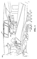
- the pedestrian perception alert system 10 may be integrated into an automotive vehicle 100.
- the pedestrian perception alert system 10 includes a video camera 12 configured to capture video images.
- the pedestrian perception alert system 10 further includes an alert 14, and a processor 16.
- the alert 14 is configured to issue a warning that the pedestrian is within the driving environment, and is visually difficult to perceive.
- the alert 14 may be disposed within the cabin space of the vehicle, and may be a visual notification such as a light, or an audible signal such as a chime, or a series of chimes.
- the processor 16 is in electrical communication with the video camera 12 and is configured to process the video image utilizing analysis units, as described below, so as to issue a warning to the driver.
- Figure 1 shows the video camera 12 mounted to the underside of a rearview mirror, it should be appreciated that the video camera 12 may be mounted elsewhere. Further, multiple video cameras 12 may be used to provide 360 degree coverage of the natural driving environment. In such an embodiment, it should be appreciated that the processor 16 may be further configured to fuse the video image caught by each video camera 12 so as to build a 360 degree view of the natural driving environment.
- the video camera 12 is a high resolution camera configured to capture a 122 degree camera view, record 32 frames per second at 1280x720 resolution, commonly referenced as the DOD GS600 Digital Video Recorder ("DVR").
- the video camera 12 may include other features such as GPS antenna 12a for obtaining geographic location, and a gravity sensor 12b for sensing motion.
- the system 10 captures video image, measures the global clutter of the image, processes the image to detect a pedestrian, utilizes pedestrian contour and color clustering to verify that the detected pedestrian is indeed a pedestrian, and then measures the clutter of the pedestrian.
- Features such as the pedestrian contour, and color of the cloth may also be used to measure the clutter.
- the output is a measurement of the difficulty a driver may have of visually perceiving the detected pedestrian within the driving environment.
- the pedestrian perception alert system 10 further includes a Pedestrian Detection Unit ("PDU”) 18, a Global Clutter Analysis Unit (“GCAU”) 20, and a Local Pedestrian Clutter Analysis Unit (“LPCAU”) 22.
- PDU Pedestrian Detection Unit
- GCAU Global Clutter Analysis Unit
- LPCAU Local Pedestrian Clutter Analysis Unit
- the PDU 18, GCAU 20, and LPCAU 22 may be manufactured as firmware with protocol configured to be processed and actuated by the processor 16.
- the firmware may be a separate unit disposed with other electronics of the vehicle.
- the PDU 18 is configured to analyze the video camera 12 image to detect a pedestrian.
- the PDU 18 may use input such as the geographic location of the vehicle gathered by the GPS antenna 12a, or motion input gathered by the gravity sensor 12b to perform pedestrian detection.
- the processor 16 actuates the PDU 18 wherein the PDU 18 analyzes predetermined frames to determine if a pedestrian is present in the natural driving environment. For instance, the PDU 18 may be configured to identify regions of interests within each frame, wherein the background of the frame is eliminated so as to focus processing and analysis on the regions of interest.
- the PDU 18 may then apply pedestrian feature matching, to include size, motion and speed, height-width ratio and orientation.
- the PDU 18 notifies the processor 16 in the event a pedestrian is present within the natural driving environment.
- the processor 16 then actuates both the GCAU 20 and the LPCAU 22 upon notification from the PDU 18.
- the GCAU 20 is configured to generate a global clutter score 24.
- the global clutter score 24 is a measurement of the clutter of the entire video image.
- the LPCAU 22 is configured to generate a local pedestrian clutter score 26.
- the local pedestrian clutter score 26 is a measurement of the clutter of each pedestrian detected in the video image.
- the processer 16 is further configured to process both the global clutter score 24 and local pedestrian clutter score 26 so as to generate a pedestrian detection score 28.
- the pedestrian detection score 28 is the difference between the global clutter score 24 and local pedestrian clutter score 26.
- the pedestrian detection score 28 measures the difficulty of visually seeing a pedestrian based upon both the amount of clutter in the driving environment and the clutter of the detected pedestrian with respect to the clutter in the environment.
- clutter refers to a combination of foreground and background in a view that provides distracting details for some individuals who are unable to detect object(s) from its background.
- the processor 16 is further configured to actuate the alert 14 when the pedestrian detection score 28 is outside of a predetermined threshold.
- the GCAU 20 measures the overall clutter score of the entire video image based upon the edge density, luminance variation and chrominance variation of the video image to calculate the global clutter score 24.
- the edge density may be calculated by applying a detector, such as a Canny detector, with fixed threshold range to detect an edge and to compare the edge density of various frames of the video image having different driving scenarios, illumination and weather conditions.
- a detector such as a Canny detector
- the lower threshold may be set to 0.11
- the upper threshold may be set to 0.27.
- a 7x7 Gaussian filter is applied to each video frame processed by the Canny detector so as to remove excess high frequency image components to which human vision is not sensitive.
- the dimensions provided herein are used for processing the dimensions and resolution of the video image captured by the DOD GS600 Digital Video Recorder, and that the dimensions may change to correspond to dimensions of resolution of the video image captured by the camera.
- the edge density is calculated as the ratio between the number of edge pixels and the total number of pixels within the frame of the video image.
- Luminance variation is measured globally. Luminance variation measures the luminance change of the entire video image 200.
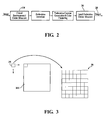
- the GCAU 20 may include a sliding window 34 and a luminance variation matrix 36, as shown in Figure 3 .
- the luminance variation matrix 36 is dimensioned the same size as the video frame.
- a 9x9 sliding window 34 is slid across the frame of the video image so as to calculate a standard deviation of luminance value within the sliding window 34 with respect to the same space of the luminance variation matrix 36.
- the standard deviation for a particular area of the video frame is entered into the corresponding position of the luminance variation matrix 36.
- the global luminance variation is calculated as the mean value of the populated luminance variation matrix 36.
- the chrominance variation is calculated using two chrominance channels, "a" and "b".
- the chrominance variation is calculated by determining the standard deviation for each respective channel.
- the global clutter score 24 may be outputted as a weighted sum of the edge density, luminance variation, and chrominance variation.
- the edge density, luminance variation, and chrominance variation may be evenly weighted, with each selected at 1/3 weighted value.
- the resultant global environmental clutter score may be scaled and normalized to a value between 0 and 1 such that the higher score means higher clutter.
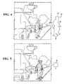
- a Pedestrian Contour Generation Unit (“PCGU") 30 is provided.
- the LPCAU 22 processes edge density of the detected pedestrian, edge distribution, local luminance variation, local chrominance variation, mean luminance intensity, and mean chrominance intensity to calculate the local pedestrian clutter score 26.
- the PCGU 30 is configured to generate a pedestrian mask 32, which may be used to obtain edge density, edge distribution, local luminance variation, local chrominance variation, mean luminance intensity and mean chrominance intensity of the detected pedestrian.
- the pedestrian mask 32 shown as a dashed silhouette of a pedestrian, is a constructed image of the pedestrian based upon features commonly associated with a pedestrian.
- the pedestrian mask 32 may include the contours of the pedestrian which are applied to the detected pedestrian so as to verify that the detected pedestrian is indeed an actual pedestrian. It should be appreciated that these features may vary based upon the location of the pedestrian within the driving environment, and/or the time at which the PCGU 30 is actuated, may be used to generate the pedestrian mask 32, and to refine the pedestrian mask 32 through subsequent video frames so as to ensure accuracy of the verification process.
- the pedestrian mask 32 is deformable model 40, as indicated by the quotation marks surrounding the pedestrian mask 32 shown in Figure 4 .
- the deformable mask is applied around the pedestrian contour 38. Energy minimization may be used to evolve the contour 38.
- E C ⁇ ⁇ ⁇ 0 1 ⁇ C ⁇ s 2 ⁇ ds + ⁇ ⁇ ⁇ 0 1 ⁇ C ⁇ s 2 ⁇ ds - ⁇ ⁇ ⁇ 0 1 ⁇ ⁇ u 0 C ⁇ s 2 ⁇ ds ,
- the generated contour 38 defines the pedestrian mask 32 which may be used by the LPCAU 22 to compute pedestrian clutter features, to include local pedestrian luminance variation and local pedestrian chrominance variation.
- the PCGU 30 may be further configured to generate a cloth mask 42.
- the cloth mask 42 may be used to replicate a human visual attention model by providing a cloth region that is homogenous in both color and luminance intensity, wherein the cloth region may be compared with the background so as to simulate the human visual attention model.
- the cloth mask 42 is generated by K-mean color clustering based cloth region segmentation which is subsequently applied to the detected pedestrian to segment the cloth region.
- S ⁇ S 1 ,...S k is the k clusters
- 1(x,y) is the chrominance pixel value
- ⁇ n is the mean value of each cluster.
- the cloth mask 42 is then formed as an intersection of the pedestrian mask 32 by active contour 38 and cloth region derived from K-mean color clustering algorithm.
- the LPCAU 22 is further configured to process the pedestrian mask 32 and the cloth mask 42 so as to compute the local pedestrian clutter score 26.
- the local pedestrian clutter score 26 may include features of shapes associated with the pedestrian which may be affected by movement of the pedestrian, the location of the pedestrian, and the color of the pedestrian's clothes.
- the LPCAU 22 may be further configured to generate a background window 44 and a detected pedestrian window 46.
- the background window 44 is a portion of the video image having a predetermined dimension of the environment surrounding the detected pedestrian.
- the detected pedestrian window 46 is a portion of the video frame dimensioned to capture the image of the detected pedestrian.
- the background window 44 may be at least twice the area of the detected pedestrian window 46.
- the LPCAU 22 is further configured to determine the ratio between the number of edge pixels and the total number of pixels within both (1) the detected pedestrian window 46 and (2) the background window 44, and absent the detected pedestrian window 46, so as to calculate an edge density for a pedestrian.
- the edge density may be calculated in a similar manner as the edge density for the global environment.
- the edge density of the background window 44 and the detected pedestrian window 46 may be calculated by applying a detector for removing excess high frequency image components with fixed threshold range to detect an edge and to compare the edge density of background window 44 with respect to the detected pedestrian window 46.
- the fixed threshold range and the detector may be selected based upon factors such as the dimensions of the detected pedestrian window 46 or the background window 44, the resolution of the video image, processing capabilities of the processor 16, and the like.
- the lower threshold may be set to .11 and the upper threshold may be set to .27.
- a 7x7 Gaussian filter is respectively applied to the detected pedestrian window 46 or the background window 44processed by a Canny detector so as to remove excess high frequency image components to which human vision is not sensitive.
- the edge density of the detected pedestrian window 46 may be calculated by applying a Canny detector with fixed threshold range to detect an edge and to compare the edge density of detected pedestrian window 46. Again, detecting the edge density of the detected pedestrian window of video image taken by the DOD GS600 Digital Video Recorder, the lower threshold may be set to 11 and the upper threshold may be set to .27.
- a 7x7 Gaussian filter is applied to the detected pedestrian window 46 processed by the Canny detector so as to remove excess high frequency image components to which human vision is not sensitive.
- the LPCAU 22 is configured to calculate an edge distribution of the background window 44 and the detected pedestrian by determining the histogram of edge magnitude binned by the edge orientation for both (1) the detected pedestrian window 46 and (2) the Isolated Background Window, wherein the Isolated Background Window is the background window 44 minus the detected pedestrian window 46.
- the edge distribution is a feature which may be used to calculate the local pedestrian clutter score 26. The edge distribution is also useful to help verify that the detected pedestrian is in fact a pedestrian.
- the LPCAU 22 may be configured to calculate the local luminance variation within the pedestrian mask 32 and also within a region defined by the subtraction of the pedestrian mask 32 from the background window 44 (the "Maskless Background Window").
- the LPCAU 22 utilizes a sliding window 34 and a mask luminance variation matrix 36.
- the mask luminance variation matrix 36 is dimensioned the same size as that of the pedestrian mask 32 so as to calculate the luminance variation of the pedestrian mask 32.
- a sliding window 34 is slid across the pedestrian mask 32 so as to calculate a standard deviation of luminance value within the sliding window 34 with respect to the same space of the mask luminance variation matrix 36.
- the standard deviation for a particular area of the pedestrian mask 32 is entered into the corresponding position of the luminance variation matrix 36.
- the luminance variation of the pedestrian mask 32 is calculated as the mean value of the populated mask luminance variation matrix 36.
- a sliding window 34 and a Maskless Background Window Luminance (the "MBWL") variation matrix 36 is provided.
- the MBWL variation matrix 36 is dimensioned the same size as the Maskless Background Window so as to calculate the luminance variation of the Maskless Background Window.
- sliding window 34 is slid across the Maskless Background Window so as to calculate a standard deviation of luminance value within the sliding window 34 with respect to the same space of the MBWL variation matrix 36.
- the standard deviation for a particular area of the Maskless Background Window is entered into the corresponding position of the MBWL variation matrix 36.
- the luminance variation of the Maskless Background Window is calculated as the mean value of the populated MBWL variation matrix 36.
- the LPCAU 22 may be further configured to calculate the local chrominance variation within the pedestrian mask 32 and also within Maskless Background Window.
- the computation of local chrominance variation is calculated using two chrominance channels, "a" and "b" for both the pedestrian mask 32 and the Maskless Background Window.
- the chrominance variation is calculated by determining the standard deviation for each respective channel.
- the LPCAU 22 may be further configured to calculate the mean luminance intensity within the cloth mask 42 and a region generated by subtracting the cloth mask 42 from the background window 44 (the "Cloth Maskless Background Region").
- the LPCAU 22 may also calculate the mean chrominance intensity within the cloth mask 42 and Cloth Maskless Background Region.
- the LPCAU 22 may calculate the local pedestrian clutter using features described above, that is the: (1) calculated edge density and edge distribution; (2) the local luminance variation of the pedestrian mask 32 and the Maskless Background Window; (3) the local chrominance variation within the pedestrian mask 32 and also within Maskless Background Window; (4) the mean luminance intensity within the cloth mask 42 and also of the Cloth Maskless Background Region, and (5) the mean chrominance intensity of the cloth mask 42 and the Cloth Maskless Background Region.
- the local pedestrian clutter score 26 is normalized to a value between 0 to 1, wherein the higher the local pedestrian clutter score 26, the more cluttered the pedestrian is, and thus the more difficult it is for a driver to perceive the pedestrian from the environment.
- the chart includes both the global clutter score 24 and the local pedestrian clutter score 26, each of which were computed in accordance with the details provided herein.
- Image 4 and 5 are of the same environment with a global clutter score 24 of 0.307.
- the global clutter score 24 provides reasonable reference to the global clutter level although they are not very discriminative while comparing some similar driving scenes.
- the local pedestrian clutter score 26 reflects the difficulty of pedestrian perception quite well compared to the global clutter score 24.
- the images indicate that (1) low contrast image tends to have lower global clutter score 24, such as night image (Image 1 with global clutter score 24 of 0.116) and image with excessive glares and reflections (Image 2 with a global clutter score 24 of 0.220); (2) color saliency is the most important factor that may affect the local pedestrian clutter score 26, e.g., Image 6 has the lowest local pedestrian clutter score 26 (0.527) due to its highly saturated and discriminative pants color compared to the neighborhood area; and (3) local pedestrian clutter could be a better indicator and reference for pedestrian perception difficulty in naturalistic driving scenarios. For example, even though Image 1 has the lowest global clutter score 24 (0.1 16), it is the most difficult to detect the pedestrian in dark clothing due to its high local pedestrian clutter score 26 (0.928).
- the pedestrian perception alert system 10 processes both the global clutter score 24 and the local pedestrian clutter score 26 so as to calculate a pedestrian detection score 28.
- the pedestrian detection score 28 may be calculated by simply determining the difference between the two scores, wherein the alert 14 is actuated when the pedestrian detection score 28 is outside of a predetermined threshold, or above a desired value.
- the global clutter score 24 or the local pedestrian clutter score 26 is weighted based upon the environment such that one of the scores factors more heavily in calculation of the pedestrian detection score 28.
- the pedestrian perception alert system 10 includes a PDU 18.
- the PDU 18 is configured to process two dimensional video to detect a pedestrian.
- the PDU 18 is configured to execute a first detection method 48 or a second detection method 50 based upon the probability of a pedestrian appearance within the video image.
- the first detection method 48 is executed in instances where there is a low chance of pedestrian appearance and the second detection method 50 is executed in instances where there is a high chance of pedestrian appearance.
- the PDU 18 may determine a probability of a pedestrian appearance based upon the time of day, geographic location, or traffic scene. Alternatively, the PDU 18 may process a look-up table having pre-calculated or observed statistics regarding the probability of a pedestrian based upon time, geographic location, or traffic scene. For illustrative purposes, the look-up table may indicate that there is a five (5) percent probability of a pedestrian at 3:22 a.m., on December 25 th , in Beaverton, Oregon, on a dirt road. Accordingly, as the probability of a pedestrian appearance in the driving scene is relatively low, the PDU 18 executes the first detection method 48.
- the first detection method 48 is configured to identify a region of interest within the video image by determining the variation between sequential frames of the video image.
- the PDU 18 identifies a region of interest in instances where the variation between sequential frames exceeds a predetermined threshold.
- the first detection method 48 further applies a set of constraints, such as pedestrian size, shape, orientation, height-width ratio and the like, to each of the regions of interest, wherein each region of interest having a requisite number of constraints is labeled as having a pedestrian.
- the second detection method 50 is configured to determine regions of interests within the video image by detecting vertical edges within the frame.
- the PDU 18 identifies a region of interests in instances where the vertical edge has a predetermined characteristic.
- the second detection method 50 further applies a feature filter, illustratively including, but not limited to, a Histogram of Oriented Gradient detector to each region of interest, wherein each region of interest having a requisite number of features is labeled as having a pedestrian.
- the pedestrian perception alert system 10 may include additional units configured to calculate a pedestrian detection score 28.
- the pedestrian detection score 28 may be computed using the global clutter score 24, saliency measure, location prior, local pedestrian clutter score 26, pedestrian behavior analysis, and group interaction.
- the Factors may be processed together by the processor 16 to generate a Probabilistic Learned Model (the "PLM") which may be further processed so as to generate a pedestrian detection score 28.
- the PLM stores the Factors over time and calculates the pedestrian detection score 28 based in part upon the learned influence one Factor may have upon the other Factor.
- the PLM is helpful in refining and providing an accurate pedestrian detection score through learned experiences.
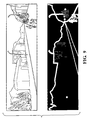
- the pedestrian perception alert system 10 may further include a Saliency Map Generating Unit ("SMGU") 52.
- the SMGU 52 is configured to process the video image and extract salient features from the video image.
- the SMGU 52 is directed to replicating the human vision system wherein between the pre-attention stage and the recognition state task and target functions of the human vision system are completed.
- the SMGU 52 computes and generates a task and target independent bottom up saliency map using saliency computation approaches currently known and used in the art, illustratively including the saliency map shown in Figure 9 .
- the map shows strong connected edges of the image above. Specifically, the region with high salient features has high intensity.
- the processor 16 processes the extracted salient features and provides the salient features to the LPCAU 22 so as to generate a local pedestrian clutter score 26.
- the salient features may include, but are not limited to: (1) edges of the image; and (2) connecting edges of the image.
- the pedestrian perception alert system 10 may be further configured to process pedestrian behavior to calculate the pedestrian detection score 28.
- Pedestrian behavior may include how the pedestrian motion affects the perception difficulty of the driver, and may be further used to verify pedestrian detection.
- Pedestrian behavior may also be examined in the context of the environment. Wherein pedestrian behavior includes analyzing the location and status of the appearing pedestrians, including standing, walking, running, carrying objects, etc., the perceived pedestrian clutter determined/calculated by the environment surrounding the pedestrian.
- the SMGU 52 may be programmed with the behavior of a pedestrian at an urban cross walk, or on a side walk adjacent a residential street.
- the pedestrian perception alert system 10 may further include a Pedestrian Group Analysis Unit (“PGAU”) 54 configured to detect a group of pedestrians and assign a perception difficulty value to the group of pedestrians.
- the PGAU 54 analyzes individual pedestrian interaction within the group of pedestrians, and the interaction of one group of pedestrians with respect to another group of pedestrians. For the within group interaction case, pedestrians located close within the scene with similar behavior pattern, e.g. standing/crossing/walking in the same direction, may grouped by the viewer so that the clutter score of an individual pedestrian within the group will be limited to describe the pedestrian perception difficulty. Accordingly, a high cluttered pedestrian would be much easier to detect if he/she were grouped by the viewer into a group with much more salient pedestrians.
- the PGAU 54 utilizes group pedestrians' characteristics combined with individual pedestrian clutter features in judgment of visual clutter.
- the PGAU 54 accounts for the fact that the perception of a pedestrian may also be affected by other pedestrians or distracting events/objects existing in the same scene. For example, a moving pedestrian may distract driver's attention more easily relative to a static pedestrian, and a dashing vehicle or bicycle may catch the attention of driver immediately.
- the PGAU 54 may utilize learned behavior of pedestrians in group interactions to calculate the pedestrian detection score 28.
- a method for issuing alert 14 in real-time when a driver's visual detection of a pedestrian is difficult includes the steps of providing a video camera 12, an alert 14 and a processor 16. These steps are referenced in Figure 8 as 110, 120, and 130 respectively.
- the video camera 12 is configured to capture video image.
- the alert 14 is configured to issue a warning that the pedestrian within the driving environment is difficult to visually perceive.
- the processor 16 is in electrical communication with the camera and processes the video image.
- the method further includes detecting a pedestrian in the video image 140, measuring the clutter of the entire video image 150, measuring the clutter of each of the pedestrians detected in the video image 160, calculating a global clutter score 170, calculating a local pedestrian clutter score 180.
- the method 100 proceeds to step 190 wherein the global clutter score and local pedestrian clutter score are processed so as to calculate a pedestrian detection score, and in step 200 the method issues a warning when the pedestrian detection score is outside of a predetermined threshold so as to notify the driver that visual perception of a pedestrian is difficult.
- the method 100 may utilize the PDU 18, GCAU 20, and LPCAU 22 as described herein so as to detect a pedestrian, measure global clutter and pedestrian clutter, and calculate a global clutter score and a local pedestrian clutter score.
- the PDU 18 analyzes the video camera 12 image to detect a pedestrian.
- the GCAU 20 generates the global clutter score 24 which measures the clutter of the entire video image.
- the LPCAU 22 generates the local pedestrian clutter score 26 which measures the clutter of each of the pedestrians detected in the video image.
- the both the GCAU 20 and the LPCAU 22 are initiated when the PDU 18 detects a pedestrian in the video image.
- the GCAU 20 and the LPCAU 22 may calculate a respective global clutter score 24 and local pedestrian clutter score 26 as described herein.
- the method proceeds to the step of processing the global clutter score 24 and local pedestrian clutter score 26 so as to generate a pedestrian detection score 28, and actuating the alert 14 when a pedestrian detection score 28 is outside of a predetermined threshold.
- the method may further include step 210, a generating a pedestrian mask 32.
- the PCGU 30 may be configured to generate the pedestrian mask 32.
- the pedestrian mask 32 is a constructed image of the pedestrian based upon features commonly associated with a pedestrian.
- the pedestrian mask 32 includes the contour of the pedestrian which are applied to the detected pedestrian so as to verify that the detected pedestrian is indeed an actual pedestrian. It should be appreciated that these features may vary based upon the location of the pedestrian within the driving environment, and/or the time at which the PCGU 30 is actuated, may be used to generate the pedestrian mask 32, and to refine the pedestrian mask 32 through subsequent video frames so as to ensure accuracy of the verification process.
- the pedestrian mask 32 is a deformable model 40 which is applied around the pedestrian contour 38.
- Energy minimization may be used to evolve the contour 38.
- C'(s) is the tangent of the curve and C''(s) is normal to the curve.
- G ⁇ is a Gaussian smooth filter and ⁇ u 0 is the image gradient.
- the generated contour 38 defines the pedestrian mask 32 which may be used by the LPCAU 22 to compute pedestrian clutter features, to include local pedestrian luminance variation and local pedestrian chrominance variation.
- the method may include utilizing edge density, luminance variation and chrominance variation of the video image to calculate the global clutter score 24 and edge density of the detected pedestrian, edge distribution, local luminance variation, local chrominance variation, mean luminance intensity, and mean chrominance intensity to calculate the local pedestrian clutter score 26.
- the pedestrian detection score 28 is the difference between the global clutter score 24 and local pedestrian score.
- Edge density may be calculated by removing high frequency image components and subsequently determining a ratio between the number of edge pixels and the total number of pixels within the video frame.
- the method may utilize a sliding window 34 and a luminance variation matrix 36 dimensioned the same size as the video frame, to calculate the luminance variation, wherein the GCAU 20 is configured to slide the sliding window 34 across the entire video frame so as to calculate a standard deviation of luminance value within the sliding window 34.
- the luminance variance may be calculated by entering the standard deviation for a particular area of the video frame into the corresponding position of the luminance variation matrix 36, and calculating the mean value of the luminance matrix.
- the chrominance variation may be calculated using two chrominance channels as described above.
- the global clutter score 24 may be outputted as a weighted sum of the edge density, luminance variation, and chrominance variation.
- the edge density, luminance variation, and chrominance variation may be evenly weighted, with each selected at 1/3 weighted value.
- the resultant global environmental clutter score may be scaled and normalized to a value between 0 and 1 such that the higher score means higher clutter.
- the LPCAU 22 may be further configured to generate a background window 44 and a detected pedestrian window 46.
- the background window 44 is a portion of the video image having a predetermined dimension of the environment surrounding the detected pedestrian.
- the detected pedestrian window 46 is a portion of the video frame dimensioned to capture the image of the detected pedestrian.
- the background window 44 may be at least twice the area of the detected pedestrian window 46.
- the LPCAU 22 is further configured to determine the ratio between the number of edge pixels and the total number of pixels within both (1) the detected pedestrian window 46 and (2) the background window 44 and absent the detected pedestrian window 46, so as to calculate an edge density for a pedestrian.
- the LPCAU 22 is configured to calculate an edge distribution of the background window 44 and the detected pedestrian by determining the histogram of edge magnitude binned by the edge orientation for both (1) the detected pedestrian window 46 and (2) the Isolated Background Window, as defined herein.
- the edge distribution is a feature which may be used to calculate the local pedestrian clutter score 26. The edge distribution is also useful to help verify that the detected pedestrian is in fact a pedestrian.
- the LPCAU 22 may be configured to calculate the local luminance variation within the pedestrian mask 32 and also within a region defined by the subtraction of the pedestrian mask 32 from the background window 44 (the "Maskless Background Window").
- the LPCAU 22 utilizes a sliding window 34 and a mask luminance variation matrix 36.
- the mask luminance variation matrix 36 is dimensioned the same size as that of the pedestrian mask 32 so as to calculate the luminance variation of the pedestrian mask 32.
- a sliding window 34 is slid across the pedestrian mask 32 so as to calculate a standard deviation of luminance value within the sliding window 34 with respect to the same space of the mask luminance variation matrix 36.
- the standard deviation for a particular area of the pedestrian mask 32 is entered into the corresponding position of the luminance variation matrix 36.
- the luminance variation of the pedestrian mask 32 is calculated as the mean value of the populated mask luminance variation matrix 36.
- a sliding window 34 and a MBWL variation matrix 36 is provided.
- the MBWL variation matrix 36 is dimensioned the same size as the Maskless Background Window so as to calculate the luminance variation of the Maskless Background Window.
- sliding window 34 is slid across the Maskless Background Window so as to calculate a standard deviation of luminance value within the sliding window 34 with respect to the same space of the MBWL variation matrix 36.
- the standard deviation for a particular area of the Maskless Background Window is entered into the corresponding position of the MBWL variation matrix 36.
- the luminance variation of the Maskless Background Window is calculated as the mean value of the populated MBWL variation matrix 36.
- the LPCAU 22 may be further configured to calculate the local chrominance variation within the pedestrian mask 32 and also within Maskless Background Window.
- the computation of local chrominance variation is calculated using two chrominance channels, "a" and "b" for both the pedestrian mask 32 and the Maskless Background Window.
- the chrominance variation is calculated by determining the standard deviation for each respective channel.
- the LPCAU 22 may be further configured to calculate the mean luminance intensity within the cloth mask 42 and a region generated by subtracting the cloth mask 42 from the background window 44 (the "Cloth Maskless Background Region").
- the LPCAU 22 may also calculate the mean chrominance intensity within the cloth mask 42 and Cloth Maskless Background Region.
- the LPCAU 22 may calculate the local pedestrian clutter using features described above, that is the: (1) calculated edge distribution; (2) the local luminance variation of the pedestrian mask 32 and the Maskless Background Window; (3) the local chrominance variation within the pedestrian mask 32 and also within Maskless Background Window; (4) the mean luminance intensity within the cloth mask 42 and also of the Cloth Maskless Background Region, and (5) the mean chrominance intensity of the cloth mask 42 and the Cloth Maskless Background Region.
- the local pedestrian clutter score 26 is normalized to a value between 0 to 1, wherein the higher the local pedestrian clutter score 26, the more cluttered the pedestrian is, and thus the more difficult it is for a human to perceive the pedestrian from the environment.
- the method includes the step of providing a PDU 18 to detect a pedestrian.
- the PDU 18 is configured to execute a first detection method 48 or a second detection method 50 based upon the probability of a pedestrian appearance within the video image.
- the first detection method 48 is executed in instances where there is a low chance of pedestrian appearance and the second detection method 50 is executed in instances where there is a high chance of pedestrian appearance.
- the PDU 18 may determine a probability of a pedestrian appearance based upon the time of day, geographic location, or traffic scene. Alternatively, the PDU 18 may process a look-up table having pre-calculated or observed statistics regarding the probability of a pedestrian based upon time, geographic location, or traffic scene. For illustrative purposes, the look-up table may indicate that there is a five (5) percent probability of a pedestrian at 0322 AM, during December 25 th , in Beaverton Oregon, on a dirt road. Accordingly, as the probability of a pedestrian appearance in the driving scene is relatively low, the PDU 18 executes the first detection method 48.
- the first detection method 48 is configured to identify regions of interests within the video image by determining the variation between sequential frames of the video image.
- the PDU 18 identifies a region of interests in instances where the variation between sequential frames exceeds a predetermined threshold.
- the first detection method 48 further applies a set of constraints, such as pedestrian size, shape, orientation, height-width ratio and the like to each of the regions of interest, wherein each region of interest having a requisite number of constraints is labeled as having a pedestrian.
- the second detection method 50 is configured to determine regions of interests within the video image by detecting vertical edges within the frame.
- the PDU 18 identifies a region of interests in instances where the vertical edge has a predetermined characteristic.
- the second detection method 50 further applies a feature filter, illustratively including, but not limited to, a Histogram of Oriented Gradient detector, to each region of interest, wherein each region of interest having a requisite number of features is labeled as having a pedestrian.
- the method may include the processing of additional features to calculate a pedestrian detection score 28.
- the pedestrian detection score 28 may be computed using the global clutter score 24, saliency measure, location prior, local pedestrian clutter score 26, pedestrian behavior analysis, and group interaction, (each referenced hereafter as a "Factor” and collectively as the “Factors”).
- the Factors may be processed together by the processor 16 to generate a Probabilistic Learned Model (the "PLM”) which may be further processed so as to generate a pedestrian detection score 28.
- the PLM stores the Factors over time and calculates the pedestrian detection score 28 based in part upon the learned influence one Factor may have upon the other Factor. Thus, the PLM is helpful in refining and providing an accurate pedestrian detection score through learned experiences.
- the method may further include the step of providing a Saliency Map Generating Unit ("SMGU 52").
- the SMGU 52 is configured to process the video image and extract salient features from the video image.
- the SMGU 52 is directed to replicating the human vision system wherein between the pre-attention stage and the recognition state task and target functions of the human vision system are completed.
- the SMGU 52 computes and generates a task and target independent bottom up saliency map using saliency computation approaches currently known and used in the art, illustratively including the saliency map shown in Figure 9 .
- the map shows strong connected edges of the image above. Specifically, the region with high salient features has high intensity.
- the processor 16 processes the extracted salient features and provides the salient features to the LPCAU 22 so as to generate a local pedestrian clutter score 26.
- the salient features may include, but are not limited to: (1) edges of the image; and (2) connecting edges of the image.
- the method may further include step 220, processing pedestrian behavior to calculate the pedestrian detection score 28.
- Pedestrian behavior may include how the pedestrian motion affects the perception difficulty of the driver, and may be further used to verify pedestrian detection.
- Pedestrian behavior may also be examined in the context of the environment. Wherein pedestrian behavior includes analyzing the location and status of the appearing pedestrians, including standing, walking, running, carrying objects, etc., the perceived pedestrian clutter determined/calculated by the environment surrounding the pedestrian.
- the SMGU 52 may be programmed with the behavior of a pedestrian at an urban cross walk, or on a side walk adjacent a residential street.
- the method may further include step 230, analyzing individual pedestrian interaction within the group of pedestrians, and the interaction of one group of pedestrians with respect to another group of pedestrians to calculate the pedestrian detection score.
- a Pedestrian Group Analysis Unit (“PGAU 54") is configured to detect a group of pedestrians and assign a perception difficulty value to the group of pedestrians.
- the PGAU 54 analyzes individual pedestrian interaction within the group of pedestrians, and the interaction of one group of pedestrians with respect to another group of pedestrians. For the within group interaction case, pedestrians located close within the scene with similar behavior pattern, e.g., standing/crossing/walking in the same direction, may grouped by the viewer so that the clutter score of an individual pedestrian within the group will be limited to describe the pedestrian perception difficulty. Accordingly, a high cluttered pedestrian would be much easier to detect if he/she grouped by the viewer into a group with much more salient pedestrians.
- the PGAU 54 utilizes group pedestrians' characteristics combined with individual pedestrian clutter features in judgment of visual clutter.
- the PGAU 54 accounts for the fact that the perception of a pedestrian may also be affected by other pedestrians or distracting events/objects existing in the same scene. For example, a moving pedestrian may distract driver's attention more easily relative to a static pedestrian, and a dashing vehicle or bicycle may catch the attention of driver immediately.
- the PGAU 54 may utilize learned behavior of pedestrians in group interactions to calculate the pedestrian detection score 28.
Applications Claiming Priority (1)
| Application Number | Priority Date | Filing Date | Title |
|---|---|---|---|
| US14/034,103 US9070023B2 (en) | 2013-09-23 | 2013-09-23 | System and method of alerting a driver that visual perception of pedestrian may be difficult |
Publications (3)
| Publication Number | Publication Date |
|---|---|
| EP2851841A2 true EP2851841A2 (fr) | 2015-03-25 |
| EP2851841A3 EP2851841A3 (fr) | 2015-05-20 |
| EP2851841A8 EP2851841A8 (fr) | 2015-07-29 |
Family
ID=51726293
Family Applications (1)
| Application Number | Title | Priority Date | Filing Date |
|---|---|---|---|
| EP20140182908 Ceased EP2851841A3 (fr) | 2013-09-23 | 2014-08-29 | Système et procédé permettant d'alerter un conducteur que la perception visuelle d'un piéton peut être difficile |
Country Status (3)
| Country | Link |
|---|---|
| US (1) | US9070023B2 (fr) |
| EP (1) | EP2851841A3 (fr) |
| JP (1) | JP6144656B2 (fr) |
Cited By (1)
| Publication number | Priority date | Publication date | Assignee | Title |
|---|---|---|---|---|
| EP3249629A3 (fr) * | 2016-05-27 | 2018-03-21 | Kabushiki Kaisha Toshiba | Dispositif de traitement d'informations, procédé de traitement d'informations et véhicule |
Families Citing this family (20)
| Publication number | Priority date | Publication date | Assignee | Title |
|---|---|---|---|---|
| WO2014085953A1 (fr) * | 2012-12-03 | 2014-06-12 | Harman International Industries, Incorporated | Système et procédé de détection de piétons à l'aide d'un seul appareil de prise de vues ordinaire |
| JP5886809B2 (ja) * | 2013-09-27 | 2016-03-16 | 富士重工業株式会社 | 車外環境認識装置 |
| US9330334B2 (en) * | 2013-10-24 | 2016-05-03 | Adobe Systems Incorporated | Iterative saliency map estimation |
| US10019823B2 (en) | 2013-10-24 | 2018-07-10 | Adobe Systems Incorporated | Combined composition and change-based models for image cropping |
| US9299004B2 (en) | 2013-10-24 | 2016-03-29 | Adobe Systems Incorporated | Image foreground detection |
| KR101498114B1 (ko) * | 2013-11-28 | 2015-03-05 | 현대모비스 주식회사 | 보행자를 검출하는 영상 처리 장치 및 그 방법 |
| CN104717457B (zh) * | 2013-12-13 | 2018-05-18 | 华为技术有限公司 | 一种视频浓缩方法及装置 |
| US10095935B2 (en) * | 2013-12-20 | 2018-10-09 | Magna Electronics Inc. | Vehicle vision system with enhanced pedestrian detection |
| JP6483360B2 (ja) * | 2014-06-30 | 2019-03-13 | 本田技研工業株式会社 | 対象物認識装置 |
| US9747812B2 (en) * | 2014-10-22 | 2017-08-29 | Honda Motor Co., Ltd. | Saliency based awareness modeling |
| US9789822B2 (en) * | 2015-10-22 | 2017-10-17 | Feniex Industries, Inc. | Mirror controller unit for emergency vehicle warning devices |
| US20170206426A1 (en) * | 2016-01-15 | 2017-07-20 | Ford Global Technologies, Llc | Pedestrian Detection With Saliency Maps |
| US9858817B1 (en) * | 2016-10-04 | 2018-01-02 | International Busines Machines Corporation | Method and system to allow drivers or driverless vehicles to see what is on the other side of an obstruction that they are driving near, using direct vehicle-to-vehicle sharing of environment data |
| US10429926B2 (en) * | 2017-03-15 | 2019-10-01 | International Business Machines Corporation | Physical object addition and removal based on affordance and view |
| JP7028099B2 (ja) * | 2018-08-02 | 2022-03-02 | 日本電信電話株式会社 | 候補領域推定装置、候補領域推定方法、及びプログラム |
| US11030465B1 (en) * | 2019-12-01 | 2021-06-08 | Automotive Research & Testing Center | Method for analyzing number of people and system thereof |
| US11565653B2 (en) | 2020-01-03 | 2023-01-31 | Aptiv Technologies Limited | Vehicle occupancy-monitoring system |
| EP3845431A3 (fr) | 2020-01-06 | 2021-07-28 | Aptiv Technologies Limited | Système de surveillance de conducteur |
| CN113034908A (zh) * | 2021-03-12 | 2021-06-25 | 深圳市雷铭科技发展有限公司 | 基于智慧路灯的交通状况提示方法、电子设备及存储介质 |
| US11718314B1 (en) * | 2022-03-11 | 2023-08-08 | Aptiv Technologies Limited | Pedestrian alert system |
Family Cites Families (34)
| Publication number | Priority date | Publication date | Assignee | Title |
|---|---|---|---|---|
| US4181917A (en) | 1977-07-01 | 1980-01-01 | Quadricolor Technology L.P. | Color television receiving system utilizing inferred high frequency signal components to reduce color infidelities in regions of color transitions |
| US5053864A (en) | 1989-06-01 | 1991-10-01 | Thompson Electronics Ltd. | Video capture, compression and display system, including averaging of chrominance information |
| US5602760A (en) | 1994-02-02 | 1997-02-11 | Hughes Electronics | Image-based detection and tracking system and processing method employing clutter measurements and signal-to-clutter ratios |
| US6081753A (en) | 1996-03-12 | 2000-06-27 | The United States Of America As Represented By The Secretary Of The Army | Method of determining probability of target detection in a visually cluttered scene |
| JP4752158B2 (ja) * | 2001-08-28 | 2011-08-17 | 株式会社豊田中央研究所 | 環境複雑度演算装置、環境認識度合推定装置及び障害物警報装置 |
| US7885453B1 (en) | 2007-06-07 | 2011-02-08 | Cognex Technology And Investment Corporation | Image preprocessing for probe mark inspection |
| US7409092B2 (en) * | 2002-06-20 | 2008-08-05 | Hrl Laboratories, Llc | Method and apparatus for the surveillance of objects in images |
| US7657059B2 (en) | 2003-08-08 | 2010-02-02 | Lockheed Martin Corporation | Method and apparatus for tracking an object |
| EP1709568A4 (fr) * | 2003-12-15 | 2009-07-29 | Sarnoff Corp | Procede et appareil de suivi d'objets avant la detection imminente d'une collision |
| EP1544792A1 (fr) | 2003-12-18 | 2005-06-22 | Thomson Licensing S.A. | Dispositif et procédé pour la création d'une cartographie des caractéristiques saillantes d'une image |
| JP4638143B2 (ja) * | 2003-12-26 | 2011-02-23 | 富士重工業株式会社 | 車両用運転支援装置 |
| JP2007531121A (ja) * | 2004-03-24 | 2007-11-01 | セルニウム コーポレイション | エリアごとの分割ゲインの使用によるビデオ分析の改良 |
| US7454058B2 (en) * | 2005-02-07 | 2008-11-18 | Mitsubishi Electric Research Lab, Inc. | Method of extracting and searching integral histograms of data samples |
| DE602005017376D1 (de) | 2005-06-27 | 2009-12-10 | Honda Res Inst Europe Gmbh | Räumliche Annäherung und Objekterkennung für humanoiden Roboter |
| US7804980B2 (en) * | 2005-08-24 | 2010-09-28 | Denso Corporation | Environment recognition device |
| US7460951B2 (en) * | 2005-09-26 | 2008-12-02 | Gm Global Technology Operations, Inc. | System and method of target tracking using sensor fusion |
| US7881554B2 (en) | 2006-06-05 | 2011-02-01 | Stmicroelectronics S.R.L. | Method for correcting a digital image |
| JP4670805B2 (ja) * | 2006-12-13 | 2011-04-13 | 株式会社豊田中央研究所 | 運転支援装置、及びプログラム |
| US7796056B2 (en) * | 2007-03-28 | 2010-09-14 | Fein Gene S | Digital windshield information system employing a recommendation engine keyed to a map database system |
| WO2008139530A1 (fr) * | 2007-04-27 | 2008-11-20 | Honda Motor Co., Ltd. | Dispositif de surveillance de périphérie de véhicule, programme de surveillance de périphérie de véhicule et procédé de surveillance de périphérie de véhicule |
| EP2250624B1 (fr) | 2008-03-14 | 2011-12-21 | Panasonic Corporation | Procédé de traitement d'image et appareil de traitement d'image |
| US8396282B1 (en) | 2008-10-31 | 2013-03-12 | Hrl Labortories, Llc | Method and system for computing fused saliency maps from multi-modal sensory inputs |
| US8611590B2 (en) * | 2008-12-23 | 2013-12-17 | Canon Kabushiki Kaisha | Video object fragmentation detection and management |
| JP5136504B2 (ja) * | 2009-04-02 | 2013-02-06 | トヨタ自動車株式会社 | 物体識別装置 |
| US8395529B2 (en) * | 2009-04-02 | 2013-03-12 | GM Global Technology Operations LLC | Traffic infrastructure indicator on head-up display |
| US8704653B2 (en) * | 2009-04-02 | 2014-04-22 | GM Global Technology Operations LLC | Enhanced road vision on full windshield head-up display |
| US8350724B2 (en) * | 2009-04-02 | 2013-01-08 | GM Global Technology Operations LLC | Rear parking assist on full rear-window head-up display |
| US8384532B2 (en) * | 2009-04-02 | 2013-02-26 | GM Global Technology Operations LLC | Lane of travel on windshield head-up display |
| US8509526B2 (en) | 2010-04-13 | 2013-08-13 | International Business Machines Corporation | Detection of objects in digital images |
| US8294794B2 (en) * | 2010-07-06 | 2012-10-23 | GM Global Technology Operations LLC | Shadow removal in an image captured by a vehicle-based camera for clear path detection |
| US8345100B2 (en) * | 2010-07-06 | 2013-01-01 | GM Global Technology Operations LLC | Shadow removal in an image captured by a vehicle-based camera using an optimized oriented linear axis |
| JP5386538B2 (ja) * | 2011-05-12 | 2014-01-15 | 富士重工業株式会社 | 環境認識装置 |
| US8731291B2 (en) * | 2012-09-24 | 2014-05-20 | Eastman Kodak Company | Estimating the clutter of digital images |
| US8897560B2 (en) * | 2012-09-24 | 2014-11-25 | Eastman Kodak Company | Determining the estimated clutter of digital images |
-
2013
- 2013-09-23 US US14/034,103 patent/US9070023B2/en active Active
-
2014
- 2014-08-29 EP EP20140182908 patent/EP2851841A3/fr not_active Ceased
- 2014-09-22 JP JP2014192637A patent/JP6144656B2/ja active Active
Non-Patent Citations (1)
| Title |
|---|
| None |
Cited By (3)
| Publication number | Priority date | Publication date | Assignee | Title |
|---|---|---|---|---|
| EP3249629A3 (fr) * | 2016-05-27 | 2018-03-21 | Kabushiki Kaisha Toshiba | Dispositif de traitement d'informations, procédé de traitement d'informations et véhicule |
| US10451735B2 (en) | 2016-05-27 | 2019-10-22 | Kabushiki Kaisha Toshiba | Information processing device, information processing method, and vehicle |
| US11536833B2 (en) | 2016-05-27 | 2022-12-27 | Kabushiki Kaisha Toshiba | Information processing device, information processing method, and vehicle |
Also Published As
| Publication number | Publication date |
|---|---|
| US9070023B2 (en) | 2015-06-30 |
| US20150086077A1 (en) | 2015-03-26 |
| JP2015062121A (ja) | 2015-04-02 |
| EP2851841A3 (fr) | 2015-05-20 |
| EP2851841A8 (fr) | 2015-07-29 |
| JP6144656B2 (ja) | 2017-06-07 |
Similar Documents
| Publication | Publication Date | Title |
|---|---|---|
| US9070023B2 (en) | System and method of alerting a driver that visual perception of pedestrian may be difficult | |
| CN107463890B (zh) | 一种基于单目前视相机的前车检测与跟踪方法 | |
| US8810653B2 (en) | Vehicle surroundings monitoring apparatus | |
| JP4173901B2 (ja) | 車両周辺監視装置 | |
| CN100545867C (zh) | 航拍交通视频车辆快速检测方法 | |
| US9047518B2 (en) | Method for the detection and tracking of lane markings | |
| JP4173902B2 (ja) | 車両周辺監視装置 | |
| JP2015062121A5 (fr) | ||
| CN110415544B (zh) | 一种灾害天气预警方法及汽车ar-hud系统 | |
| JP4528283B2 (ja) | 車両周辺監視装置 | |
| US20150169980A1 (en) | Object recognition device | |
| JP2013537661A (ja) | ステレオビジョン技術を使用することによる移動物体の自動検出 | |
| US8174578B2 (en) | Vehicle periphery monitoring device | |
| CN109313699A (zh) | 用于对一车辆的输入图像进行目标识别的装置和方法 | |
| Lion et al. | Smart speed bump detection and estimation with kinect | |
| JP4813304B2 (ja) | 車両周辺監視装置 | |
| CN112613568B (zh) | 基于可见光及红外多光谱图像序列的目标识别方法和装置 | |
| CN105021573A (zh) | 用于基于跟踪的视距估计的方法和设备 | |
| CN103093204B (zh) | 行为监测方法及装置 | |
| CN110659551A (zh) | 运动状态的识别方法、装置及车辆 | |
| US20130070098A1 (en) | Apparatus for monitoring surroundings of a vehicle | |
| Wibowo et al. | Implementation of Background Subtraction for Counting Vehicle Using Mixture of Gaussians with ROI Optimization | |
| JP2003256844A (ja) | パターン推定方法、パターン推定装置、パターン推定方法のプログラムおよびこのプログラムを記録した記録媒体 | |
| Kou et al. | A lane boundary detection method based on high dynamic range image | |
| KR20230076703A (ko) | 딥러닝 기반의 상대적 거리 예측을 이용한 접촉 감지 장치 및 방법 |
Legal Events
| Date | Code | Title | Description |
|---|---|---|---|
| PUAI | Public reference made under article 153(3) epc to a published international application that has entered the european phase |
Free format text: ORIGINAL CODE: 0009012 |
|
| 17P | Request for examination filed |
Effective date: 20140829 |
|
| AK | Designated contracting states |
Kind code of ref document: A2 Designated state(s): AL AT BE BG CH CY CZ DE DK EE ES FI FR GB GR HR HU IE IS IT LI LT LU LV MC MK MT NL NO PL PT RO RS SE SI SK SM TR |
|
| AX | Request for extension of the european patent |
Extension state: BA ME |
|
| PUAL | Search report despatched |
Free format text: ORIGINAL CODE: 0009013 |
|
| RIN1 | Information on inventor provided before grant (corrected) |
Inventor name: JIANG, PINGGE Inventor name: YANG, KAI Inventor name: DU, ELIZA Y. Inventor name: SHERONY, RINI Inventor name: TAKAHASHI, HIROYUKI |
|
| AK | Designated contracting states |
Kind code of ref document: A3 Designated state(s): AL AT BE BG CH CY CZ DE DK EE ES FI FR GB GR HR HU IE IS IT LI LT LU LV MC MK MT NL NO PL PT RO RS SE SI SK SM TR |
|
| AX | Request for extension of the european patent |
Extension state: BA ME |
|
| RIC1 | Information provided on ipc code assigned before grant |
Ipc: G06K 9/00 20060101AFI20150414BHEP Ipc: G06K 9/62 20060101ALI20150414BHEP |
|
| RAP1 | Party data changed (applicant data changed or rights of an application transferred) |
Owner name: TOYOTA JIDOSHA KABUSHIKI KAISHA Owner name: INDIANA UNIVERSITY RESEARCH AND TECHNOLOGY CORPORA Owner name: TOYOTA MOTOR ENGINEERING & MANUFACTURING NORTH AME |
|
| RIN1 | Information on inventor provided before grant (corrected) |
Inventor name: YANG, KAI Inventor name: SHERONY, RINI Inventor name: JIANG, PINGGE Inventor name: TAKAHASHI, HIROYUKI Inventor name: DU, ELIZA Y. |
|
| RAP1 | Party data changed (applicant data changed or rights of an application transferred) |
Owner name: INDIANA UNIVERSITY RESEARCH AND TECHNOLOGY CORPORA Owner name: TOYOTA MOTOR ENGINEERING & MANUFACTURING NORTH AME Owner name: TOYOTA JIDOSHA KABUSHIKI KAISHA |
|
| R17P | Request for examination filed (corrected) |
Effective date: 20151019 |
|
| RBV | Designated contracting states (corrected) |
Designated state(s): AL AT BE BG CH CY CZ DE DK EE ES FI FR GB GR HR HU IE IS IT LI LT LU LV MC MK MT NL NO PL PT RO RS SE SI SK SM TR |
|
| RAP1 | Party data changed (applicant data changed or rights of an application transferred) |
Owner name: TOYOTA MOTOR ENGINEERING & MANUFACTURING NORTH AME Owner name: TOYOTA JIDOSHA KABUSHIKI KAISHA Owner name: INDIANA UNIVERSITY RESEARCH AND TECHNOLOGY CORPORA |
|
| STAA | Information on the status of an ep patent application or granted ep patent |
Free format text: STATUS: EXAMINATION IS IN PROGRESS |
|
| 17Q | First examination report despatched |
Effective date: 20171017 |
|
| RAP1 | Party data changed (applicant data changed or rights of an application transferred) |
Owner name: TOYOTA MOTOR ENGINEERING & MANUFACTURING NORTH AME Owner name: TOYOTA JIDOSHA KABUSHIKI KAISHA Owner name: INDIANA UNIVERSITY RESEARCH AND TECHNOLOGY CORPORA |
|
| STAA | Information on the status of an ep patent application or granted ep patent |
Free format text: STATUS: THE APPLICATION HAS BEEN REFUSED |
|
| 18R | Application refused |
Effective date: 20191104 |