EP2851734A1 - Okular - Google Patents
Okular Download PDFInfo
- Publication number
- EP2851734A1 EP2851734A1 EP14184574.3A EP14184574A EP2851734A1 EP 2851734 A1 EP2851734 A1 EP 2851734A1 EP 14184574 A EP14184574 A EP 14184574A EP 2851734 A1 EP2851734 A1 EP 2851734A1
- Authority
- EP
- European Patent Office
- Prior art keywords
- eyepiece
- endoscope
- correction
- cylindrical
- lenses
- Prior art date
- Legal status (The legal status is an assumption and is not a legal conclusion. Google has not performed a legal analysis and makes no representation as to the accuracy of the status listed.)
- Granted
Links
Images


Classifications
-
- G—PHYSICS
- G02—OPTICS
- G02B—OPTICAL ELEMENTS, SYSTEMS OR APPARATUS
- G02B25/00—Eyepieces; Magnifying glasses
- G02B25/001—Eyepieces
-
- A—HUMAN NECESSITIES
- A61—MEDICAL OR VETERINARY SCIENCE; HYGIENE
- A61B—DIAGNOSIS; SURGERY; IDENTIFICATION
- A61B1/00—Instruments for performing medical examinations of the interior of cavities or tubes of the body by visual or photographical inspection, e.g. endoscopes; Illuminating arrangements therefor
- A61B1/00163—Optical arrangements
- A61B1/00195—Optical arrangements with eyepieces
-
- A—HUMAN NECESSITIES
- A61—MEDICAL OR VETERINARY SCIENCE; HYGIENE
- A61B—DIAGNOSIS; SURGERY; IDENTIFICATION
- A61B34/00—Computer-aided surgery; Manipulators or robots specially adapted for use in surgery
- A61B34/30—Surgical robots
-
- G—PHYSICS
- G02—OPTICS
- G02B—OPTICAL ELEMENTS, SYSTEMS OR APPARATUS
- G02B21/00—Microscopes
- G02B21/0004—Microscopes specially adapted for specific applications
- G02B21/0012—Surgical microscopes
-
- G—PHYSICS
- G02—OPTICS
- G02B—OPTICAL ELEMENTS, SYSTEMS OR APPARATUS
- G02B23/00—Telescopes, e.g. binoculars; Periscopes; Instruments for viewing the inside of hollow bodies; Viewfinders; Optical aiming or sighting devices
- G02B23/24—Instruments or systems for viewing the inside of hollow bodies, e.g. fibrescopes
- G02B23/2407—Optical details
- G02B23/2453—Optical details of the proximal end
-
- G—PHYSICS
- G02—OPTICS
- G02B—OPTICAL ELEMENTS, SYSTEMS OR APPARATUS
- G02B27/00—Optical systems or apparatus not provided for by any of the groups G02B1/00 - G02B26/00, G02B30/00
- G02B27/0025—Optical systems or apparatus not provided for by any of the groups G02B1/00 - G02B26/00, G02B30/00 for optical correction, e.g. distorsion, aberration
-
- G—PHYSICS
- G02—OPTICS
- G02C—SPECTACLES; SUNGLASSES OR GOGGLES INSOFAR AS THEY HAVE THE SAME FEATURES AS SPECTACLES; CONTACT LENSES
- G02C7/00—Optical parts
- G02C7/02—Lenses; Lens systems ; Methods of designing lenses
- G02C7/08—Auxiliary lenses; Arrangements for varying focal length
- G02C7/081—Ophthalmic lenses with variable focal length
Definitions
- the present invention relates to an eyepiece, in particular an eyepiece for an endoscope, a surgical microscope or another medical application.
- Eyepieces for medical and non-medical applications typically permit positioning of the area perceived by the relaxed human eye to be sharp and correction of axis ametropia (especially hyperopia and myopia) of an eye of a user of the eyepiece , Both together is commonly referred to as focusing and is usually done by shifting the entire eyepiece or parts of the eyepiece parallel to the optical axis.
- the eyes of many people have astigmatism in addition to axis ametropia. Due to a non-rotationally symmetric curvature of the cornea, a non-rotationally symmetrical shape of the lens, a nonuniform contraction of the ciliary muscle and / or for some other reason, light rays emanating from a considered point-like object are not imaged at one point but in a line on the retina ,
- the cornea and the lens of the eye have different refractive indices in different directions or in different planes perpendicular to the optical axis. The difference between the maximum power and the minimum power is given in diopters.
- the orientation of the plane of maximum refractive power or the orientation of the plane of minimum refractive power is also specified; both axes are orthogonal to one another in the case of significantly more widespread regular astigmatism.
- An object of the present invention is to provide an improved eyepiece, in particular for medical applications, an improved endoscope, an improved surgical microscope and an improved control device for an operating robot, which are particularly useful by medical staff with astigmatism.
- An eyepiece comprises a focusing device for positioning the relaxed human eye as a sharp perceived surface and for correcting an axis-ametropia of an eye of a user of the eyepiece, and a correction device for adjustable correction of astigmatism of an eye of a user of the eyepiece.
- the eyepiece is particularly intended for use with an endoscope, a surgical microscope, another microscope, a control device for a surgical robot, a binocular, a telescope, a theodolite, a periscope, a telemeter, an Oechsle meter or a magnifying glasses and trained or component from one of said optical instruments.
- the focusing device is designed in particular for displacing the flat or curved surface, within which objects are perceived by the relaxed human eye as sharp or sharply imaged on the retina, and for the correction of hyperopia or myopia or myopia.
- the focusing device comprises a threaded or spindle drive or another device for manually or motor-wise moving the entire eyepiece or parts thereof in the direction parallel to the optical axis of the eyepiece.
- the correction device is in particular a device for setting a cylindrical refractive power of the eyepiece or a difference between a maximum refractive power and a minimum refractive power of the eyepiece and for adjusting the orientation of the plane of maximum refractive power.
- the correction device always remains completely at the eyepiece when setting the cylindrical power or when adjusting the correction of astigmatism.
- the setting of the cylindrical power or their correction is thus not by replacing or inserting or attaching or removing or removing a lens or other refractive device.
- the correction or the cylindrical power is in particular infinitely adjustable.
- the correction device comprises one or more lenses or other optical elements that are movable to set the correction effect or the cylindrical power value.
- the correction device allows a simple and fast adaptation of the eyepiece to an astigmatism of a user. Procurement and storage and insertion, attachment, removal, removal or replacement of an additional lens or the like is not required.
- the eyepiece can be used by several people with different astigmatism and by a person alternately with and without glasses, only one new setting of the correction effect is required.
- the correction device comprises, in particular, two light-refracting devices which each have different refractive powers in different planes and whose spacing is variable, or which are rotatable relative to one another.
- Each of the two or more refractive devices comprises, in particular, one or more cylindrical lenses or other lenses, lens groups or lens systems which have different refractive indices relative to different planes.
- Each of the two or more refractive devices may be achromatic or apochromatic, and in particular each comprise two or more transparent bodies of different materials.
- An achromatic or apochromatic embodiment of the correction device is further possible in that the two refractive devices have different materials with, in particular, substantially opposite dependence of the refractive index on the wavelength.
- the distance between the two refractive devices of the correction device can be changed in particular by moving or moving one or both of the refractive devices in the direction parallel to the optical axis of the eyepiece.
- the distances of a plurality of refractive means of the correction device can be changed by moving one, two or more refractive devices in the direction parallel to the optical axis of the eyepiece.
- the cylindrical correction effect or the cylindrical refractive power by rotation of a or more of the refractive devices adjustable about an axis, wherein the axis is in particular parallel to the optical axis of the eyepiece.
- An eyepiece as described here, comprises in particular a cylindrical lens with a positive and a cylindrical lens with a negative refractive power.
- the amounts of the refractive indices may be the same or different.
- the two surfaces of the cylindrical lenses facing the respective other cylindrical lens have identical radii of curvature, one of the two surfaces being convex and the other being concave.
- n is the identical refractive index of both cylindrical lenses
- d is the distance between the two cylindrical lenses
- R is the radius of curvature of the cylindrical surfaces of the cylindrical lenses facing one another.
- This equation applies to two cylindrical lenses whose sides facing away from each other are flat or plane. Notwithstanding this simple case, one or both surfaces facing away from each other may be cylindrical or otherwise curved. Instead of two cylindrical lenses so other lenses with mutually facing cylindrical surfaces are used.
- a complementary embodiment of the mutually facing surfaces of two mutually movable lenses allows a vanishing cylindrical refractive index when the two complementary surfaces touch each other.
- the two lenses can have different materials, in particular with substantially opposite dependence of the refractive indices on the wavelength.
- the two refractive means of the correction device may comprise two different refractive indices.
- the cylindrical refractive power of the correction device can disappear at an average distance of the two refractive devices and have different signs starting from this average distance at smaller and larger distances.
- Different refractive powers can be realized, for example, with the same material of the two refractive devices by different radii of curvature, or at same radii of curvature through two different materials with different refractive indices.
- the correction device has in particular an electrically, magnetically or by means of hydrostatic pressure moldable interface between two media with different refractive indices.
- the interface may be formed due to different properties of the two media that prevent mixing.
- one medium is a hydrophilic or lipophobic liquid and the other medium is a hydrophobic or lipophilic liquid.
- one medium may be liquid and the other medium gaseous.
- the arrangement of both media can be predetermined by different wetting properties of different surface areas of a chamber containing the two media.
- the interface between the two media is in particular due to different electrical and / or magnetic properties of the two media formable by an electric and / or magnetic field.
- An electric or magnetic field can be generated, for example, by means of electrodes or coils inside or outside a chamber within which the two media are arranged.
- the interface is formed by an optically transparent elastic membrane.
- one of the two media is liquid and the other medium is liquid or gaseous.
- the optically transparent elastic membrane is in particular deformed by changing the difference of the hydrostatic pressures in both media.
- a non-rotationally symmetrical configuration for example in a plane perpendicular to the optical axis of the eyepiece oblong-rectangular configuration of the arrangement of the two media can be generated at least in a central region substantially cylindrical shape of the interface between the two media.
- the interface between the two media acts like a cylindrical lens with adjustable curvature.
- an electrical or magnetic influence of the moldable interface between the two media allows a simple and robust control of the cylindrical power, without requiring a linear drive or other drive means with moving parts.
- the correction device is rotatable in particular about the optical axis of the eyepiece.
- the entire eyepiece is rotatable about the optical axis.
- the mentioned cylindrical lenses or a container in which the mentioned two media are arranged with different refractive indices rotatable about the optical axis of the eyepiece.
- An eyepiece as described here, furthermore comprises, in particular, an operating device for setting a cylindrical refractive power.
- the operating device is arranged, for example, annular and symmetrical to the optical axis of the eyepiece.
- the operating device is rotatable in particular about the optical axis of the eyepiece and coupled by a threaded or spindle drive with the correction device.
- An eyepiece as described here, further comprises in particular a further operating device for setting the orientations of maximum and minimum refractive power of the correction device.
- the further operating device is, for example, arranged annularly and symmetrically to the optical axis of the eyepiece and rotatable about the optical axis of the eyepiece and mechanically or indirectly connected to the correction device.
- scales for the cylindrical refractive index and for an angle describing the orientations of maximum and minimum refractive power are respectively arranged on the operating device and on the further operating direction.
- the correction device forms a proximal light exit surface of the eyepiece.
- the correction device forms a proximal cover glass or a window component that closes the eyepiece proximally.
- the cover glass or the window component is part of the correction device.
- An eyepiece as described here, further comprises, in particular, a motor drive device for motor-adjusting the correction device.
- the eyepiece comprises, in particular, a motor drive device for setting the cylindrical refractive power and a motor drive device for setting the orientations of the maximum and the minimum refractive power.
- a motor drive device comprises in particular a stepper motor or another electric motor, an ultrasonic motor or a piezomotor.
- a motor drive device can enable a quick adjustment of the correction effect of the correction device of the eyepiece.
- the motor drive devices may be provided with a camera and facial, iris or retina recognition device, an RFID receiver or other identification device, and a database containing parameters describing astigmatism and, optionally, other ametropias of one or more users be coupled. This may allow automatic adjustment of the eyepiece to a user as he approaches the eyepiece.
- An endoscope includes an eyepiece as described herein.
- An endoscope with an eyepiece as described here, in particular has an astigmatism that is dependent on a refractive index of a medium in which the distal end of the endoscope is arranged.
- medical endoscopes are often operated alternately in air, carbon dioxide or other gas having a refractive index close to 1 and in water or other aqueous fluid.
- the distal light entry window of the endoscope is non-spherical, for example, has the shape of a section of a circular cylinder, resulting in a refractive index of the medium in which the distal light entrance window is arranged, dependent astigmatism of the endoscope.
- the correction device of the eyepiece can also enable a correction of the refractive index of the medium-dependent astigmatism of the endoscope.
- an endoscope with astigmatism dependent on the refractive index of a medium further comprises an operating device for changing the cylindrical refractive power of the correction device by a predetermined amount, which is the difference between the astigmatism of the endoscope when the distal end is arranged in air and the astigmatism of the endoscope when the endoscope is arranged corresponds to the distal end in water.
- the operating device makes it possible to switch the correction effect of the correction device between the two correction effects required when the distal end of the endoscope is arranged in air or in water.
- Settings on the eyepiece, which are related to the astigmatism of a user's eye, can thus be preserved.
- An operating microscope includes an eyepiece as described herein.
- a control device for a surgical robot includes an eyepiece as described herein.
- a surgical robot is a device for performing medical, in particular surgical interventions by means of servomotors. Movements of instruments and tools or the surgical robot itself are not driven directly or indirectly manually, but generated by servomotors.
- the surgical robot and its drive means are controlled by medical personnel, whereby a computer can process, filter, check for safety regulations generated by the surgical personnel before forwarding the control signals or modified control signals to the drive units of the surgical robot.
- the control of a surgical robot usually requires a high degree of concentration.
- two eyepieces can be provided on a control device for a surgical robot.
- a surgical microscope or a control device as described here, comprises in particular a storage device for receiving a pair of spectacles.
- Medical staff with ametropia which uses the surgical microscope or the control device, can store his glasses directly on the surgical microscope or on the control device.
- FIG. 1 3 shows a schematic representation of an endoscope 10 having a distal end 12 and a proximal end 14.
- a straight and rigid shaft 16 extends from the distal end 12 to the proximal end 14 of the endoscope 10.
- the viewing direction 18 of the endoscope 10 is within an in FIG. 1 adjustable by an arcuate double arrow indicated angle range.
- FIG. 1 essentially indicated by contours.
- the optical devices described below, however, are indicated in a side view. In this case, not only the outer contours of the optical devices, as they are visible in a section along a plane containing the optical axis, but also edges that bulge in particular circular arc out of the plane, shown in projection on the drawing plane.
- circular arc-shaped edges between curved light entry surfaces or light exit surfaces on the one hand and cylindrical lateral surfaces (parallel to the optical axis) on the other hand as straight lines orthogonal to the longitudinal axis of the endoscope 10 can be seen, since these arcuate edges in planes orthogonal to the optical axis and thus orthogonal to the longitudinal axis of the endoscope 10th and to the drawing plane. Furthermore, the likewise circular-arc-shaped edges of boundary surfaces between elements cemented together can be seen as straight lines.
- the endoscope 10 comprises at the distal end 12 a window component 20 made of a material that is transparent in particular for light within the wavelength range visible to the human eye or that has the highest possible transmission.
- the window component 20 has the shape of a section of a circular cylinder jacket, wherein the cylinder axis of the circular cylinder jacket is orthogonal to the optical axis further optical device of the endoscope 10, orthogonal to the longitudinal axis of the shaft 16, orthogonal to the viewing direction 18 of the endoscope and orthogonal to the plane.
- the pivot prism 32 has in particular the shape of a dove prism and is about a pivot axis, not shown, orthogonal to the plane of the FIG. 1 swiveling to adjust the viewing direction 18.
- a lens 34 of one or more lenses or another imaging device for generating an intermediate image of an object observed by means of the endoscope 10 is arranged downstream of the pivoting prism 32.
- a rod lens system of a plurality of rod lenses 36, 37 or other relay lens system for transmitting the intermediate image generated by the lens 34 to the distal end 14 of the endoscope 10 in the shaft 16 is arranged.
- an eyepiece 40 for generating a virtual image, which is detectable by the human eye is arranged.
- the eyepiece 40 in particular comprises a plurality of lenses and simultaneously closes the endoscope 10 at the proximal end 14 in a hermetically sealed manner.
- the window member 20 at the distal end 12 of the endoscope 10 generates aberrations due to its non-spherical, but circular cylindrical shell shape, the larger the larger the ratio between the wall thickness and the radius of curvature of the window member 20 and the larger the diameter of a is by means of the pivot prism, the lens 34, the rod lens system 36, 37 and the eyepiece 40 detected light beam.
- the window component 20 has an axial astigmatism.
- the eyepiece 40 is designed to correct an astigmatism of an eye of a user of the eyepiece.
- the eyepiece has a correction device and further features and properties, which are described below with reference to FIGS FIGS. 2 to 7 are described in more detail.
- the correction device is furthermore suitable and designed for the correction of astigmatism of the endoscope 10 originating from the shape of the window component 20 which is not rotationally symmetrical to the viewing direction 18.
- operating devices 71, 72, 74 are provided, by means of which the eyepiece 40 is adjustable.
- a cylindrical refractive power of the eyepiece 40 can be adjusted by means of a first operating device 71.
- the orientations of the planes containing the optical axis of the eyepiece in which the eyepiece has a maximum or a minimum refractive power can be set by means of a second operating device 72.
- the third operating device 74 is designed to change the cylindrical refractive power of the eyepiece 40 by an amount that corresponds to the difference between the cylindrical refractive indices of the light entry surface of the window component in air and in water.
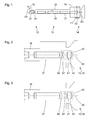
- FIG. 2 shows a schematic sectional view of an eyepiece 40 at the proximal end 14 of an in FIG. 2 only indicated endoscope 10.
- the endoscope 10 has features and properties that are described above with reference to FIG FIG. 1 are shown.
- the eyepiece 40 is arranged at the proximal end 14 of the endoscope 10 in order to generate a virtual image, which can be detected by the human eye, of an intermediate image produced by a rod lens 37.
- the eyepiece 40 comprises a first, distal lens 41 and a second, proximal lens 42, each of which is spherical or at least rotationally symmetrical with respect to the optical axis 48 of the eyepiece 40.
- the second proximal lens 42 closes the eyepiece proximally hermetically sealed.
- a transparent window component with two plane and parallel surfaces is provided for the hermetically sealed closure. Such a window component may have the advantage that it does not have to be adjusted relative to the optical axis 48 of the eyepiece.
- the eyepiece 40 comprises a correction device with a first, distal correction lens 56 and a second, proximal correction lens 57.
- Each correction lens 56, 57 has two different refractive powers in each case in two different planes which contain the optical axis 48 of the eyepiece 40.
- Each of the two correction lenses 56, 57 is designed in particular as a cylindrical lens.
- a cylinder is a body delimited by two plane and parallel surfaces, also referred to as the base and top surfaces, and by a cylindrical surface.
- the cylindrical surface is formed by parallel lines connecting corresponding points on the edges of the flat surfaces.
- a cylinder is thus created by shifting a flat surface or curve along a straight line that is not in the plane of the surface or curve.
- the base and top surfaces may be circular or have any other shape. If the base and the top surface are circular, the cylinder is a circular cylinder. If the straight lines forming the shell surface are perpendicular to the flat surfaces, the cylinder is referred to as a straight cylinder.
- a cylinder axis of a cylinder is meant any straight line which is parallel to the straight lines forming the mantle or cylindrical surface.
- the cylinder axis indicates the direction in which the cylinder is translationally invariant within certain limits.
- the cylinder axis of a straight circular cylinder is the straight line on which the centers of the base and top surfaces lie.
- the straight circular cylinder is rotationally symmetric to this axis of symmetry.
- the flat and parallel base and top surfaces of the cylinder play no role and are particularly removed or altered by grinding or otherwise.
- the light entry surface and the light exit surface are formed by parts of the lateral surface of a cylinder whose cylinder axis is in particular orthogonal to the optical axis of the optical device, the part of which is the cylindrical lens.
- the correction lenses 56, 57 are in particular cylindrical lenses whose cylinder axes orthogonal to the optical axis 48 of the eyepiece 40 and orthogonal to the plane of the FIG. 2 are.
- the correction lenses 56, 57 have (with respect to a plane orthogonal to the optical axis 48) rectangular contours.
- correction lenses 56, 57 as cylindrical lenses whose cylinder axes orthogonal to the plane of the FIG. 2
- the second correction lens 57 facing the light exit surface of the first correction lens 56 and the first correction lens 56 facing light entrance surface of the second correction lens 57, the same, in particular circular cylindrical shape.
- the first correction lens 56 is convex
- the second correction lens 57 is concave.
- the refractive power of the two facing surfaces of the correction lenses 56, 57 is zero.
- the two facing surfaces of the correction lenses 56, 57 are spaced from each other, they together have a cylindrical refractive power different from zero.
- the light entry surface of the first correction lens 56 facing away from the second correction lens 57 and the light exit surface of the second correction lens 57 facing away from the first correction lens 56 can each be flat, planar or curved. In FIG. 2 For example, a slight cylindrical curvature of the surface facing away from the first correction lens 56 of the second correction lens 57 is indicated.
- the light entry surface of the first correction lens 56 facing away from the second correction lens 57 and the light exit surface of the second correction lens 57 facing away from the first correction lens 56 may each have the shape of a section of a circular cylinder, another cylinder, a spherical surface, a surface of an ellipsoid of revolution, a surface of a torus or another shape.
- the entire eyepiece 40 is by means of a in FIG. 1 not shown operating device and a spindle drive or by means of another device not shown in the figures manually or motor in the direction parallel to the optical axis 48 of the eyepiece 40 movable.
- one or both of the spherical lenses 41, 42 of the eyepiece 40 can be moved by means of a spindle drive or otherwise manually or by motor means parallel to the optical axis 48 of the eyepiece 40.
- an astigmatism of the eye of the user of the endoscope 10 and possibly an astigmatism of the endoscope 10 can not be corrected by positioning the entire eyepiece 40 or one or both spherical lenses 41, 42 alone.
- the distance between the correction lenses 56, 57 can be changed by at least one of the two correction lenses 56, 57 being movable parallel to the optical axis 48 of the eyepiece 40.
- both correction lenses 56, 57 together or the entire eyepiece 40 are rotatable about the optical axis 48 in order to set the orientations of the planes of maximum and minimum refractive power.
- the eyepiece 40 and its components are with the in FIG. 1 shown operating means 71, 72, 74 mechanically and / or by means of magnets which allow coupling through a hermetically sealed shell coupled.
- the first operating device 71 for adjusting the cylindrical refractive power is coupled to the correction lenses 56, 57 in such a way that the distance of the correction lenses 56, 57 can be changed by means of the first operating device 71.
- the second operating device 72 is in particular coupled to the correction lenses 56, 57 in such a way that the correction lenses 56, 57 or the entire eyepiece 40 are moved around the optical axis by means of the second operating device 72 Axis 48 of the eyepiece 40 can be rotated.
- the optional third operating device 74 is designed in particular as a mechanical switch or veschiebbar or rotatable between two positions, which are defined for example by detents.
- the third operating device 74 is in particular coupled to the correction lenses 56, 57 such that by means of the third operating device 74, the cylindrical refractive power of the correction devices 56, 57 by a predetermined refractive power, the difference of the astigmatism of the endoscope 10 in the arrangement of the distal end 12 (see , FIG. 1 ) in air or water, can be changed.
- FIG. 3 shows a further schematic representation of the eyepiece 40 FIG. 2 ,
- the plane of the drawing and the type of representation correspond to those of the FIGS. 1 and 2.
- FIG. 3 shows the eyepiece 40 in a situation or configuration with respect to the situation or configuration in FIG. 2 increased distance of the correction lenses 56, 57. While the cylindrical power of the combination of both correction lenses 56, 57 at the in FIG. 2 configuration is small, it is at the in FIG. 3 shown larger configuration. By shifting the second correction lens 57 relative to the first correction lens 56, many different cylindrical powers can be set within a predetermined interval.
- FIG. 4 shows a further schematic representation of the eyepiece 40 of the FIGS. 2 and 3 ,
- the drawing plane is orthogonal to the drawing planes of the FIGS. 1 to 3 , Relative to the drawing plane of the FIG. 4 the common refractive power of both facing cylindrical curved surfaces of the correction lenses 56, 57 is zero.
- the common refractive index of the two mutually facing cylindrically curved surfaces of the correction lenses 56, 57 is only in the drawing planes of FIGS. 2 and 3 different from zero and adjustable.
- FIG. 5 shows a schematic representation of another eyepiece 40 at the proximal end 14 of an in FIG. 5 only indicated endoscopes 10.
- the plane of the drawing and the type of representation correspond to those of FIGS. 1 to 3 .
- the eyepiece 40 is similar in some features and properties to the above based on the FIGS. 2 to 4 illustrated eyepiece.
- features and properties of the eyepiece 40 are described, in which this from the above based on the FIGS. 2 to 4 differentiates.
- FIG. 5 illustrated eyepiece differs from the above based on the FIGS. 2 to 4 represented eyepiece in particular in that the two correction lenses 56, 57 are arranged proximally of the two spherical lenses 41, 42. While in the case of the FIGS. 2 to 4 The eyepiece 40, in particular the proximal spherical lens 42, which closes the eyepiece 40 in the proximal hermetically sealed manner, this object is achieved in the eyepiece 40 shown in FIG FIG. 5 represented eyepiece, in particular by the proximal correction lens 57 taken.
- the two correction lenses 56, 57 may be arranged between the two spherical lenses 41, 42. Deviating from the representations on the basis of FIGS. 2 to 5
- more than two spherical lenses and / or more than two corrective lenses 56, 57 may be provided.
- FIG. 6 shows a schematic representation of another eyepiece 40, which in some features and properties above on the basis of FIGS. 2 to 5 resembled eyepieces.
- the drawing level corresponds to the drawing levels of the FIGS. 1 to 3 and 5
- the type of representation corresponds to that of the FIGS. 1 to 5 but no contours of an endoscope are indicated.
- features and properties of the eyepiece 40 are described in which this from the above based on the FIGS. 2 to 5 differs eyepieces shown.
- FIG. 6 illustrated eyepiece 40 differs from the above based on the FIGS. 2 to 5 represented eyepieces in particular in that instead of two correction lenses whose distance is adjustable, a liquid lens having a first medium 61 and a second medium 62 is provided in a chamber 64.
- the media 61, 62 and at least the provided for passage of light wall portions of the chamber 64 are optically transparent.
- the media 61, 62 have different refractive indices so that light is refracted at the interface 66 between the media 61, 62.
- the interface 66 between the media 61, 62 may be formed by an optically transparent and mechanically elastic membrane. Alternatively, the interface 66 may result from a low miscibility of the two media 61, 62.
- one of the two media 61, 62 is liquid, the other gaseous or one of the two media 61, 62 lipophilic or hydrophobic and the other hydrophilic or lipophobic.
- both media 61, 62 have the same or a similar mass density.
- the gravitation and possibly an accelerated movement do not or only slightly affect the media 61, 62, and the shape of the interface 66 does not or only slightly depends on the orientation of the eyepiece 40 in the gravitational field of the earth and does not become affected by vibrations or changed little.
- the two media 61, 62 have different electrical properties, for example different dielectric constants.
- electrodes for generating electrostatic fields provided by means of which the shape of the interface 66 between the media 61, 62 can be influenced.
- the media 61, 62 have different magnetic properties, and on the chamber 64 are provided one or more coils for generating a magnetic field by means of which the shape of the interface 66 between the media 61, 62 can be influenced.
- the chamber 64 is in fluid communication with one or more pressure sources or surge tanks, which permit delivery or removal of one or both media 61, 62 from the chamber or into the chamber 64 to form the interface 66.
- this membrane is particularly stiffened in one direction or has anisotropic elastic properties for other reasons.
- the anisotropic elastic properties cause the membrane to curve or bulge only or predominantly in one direction and at least approximately the shape of a cylinder jacket accepts.
- the membrane may for example be guided accordingly or be clamped in a long and narrow frame in order to effect a substantially cylindrical curvature.
- the interface 66 between the two media 61, 62 results from a low miscibility of the two media 61, 62, a cylindrical or substantially cylindrical curvature of the interface 66 in particular by the shape of the chamber 64 (for example, in projection on a Plane orthogonal to the optical axis 48 long and narrow) and / or by the shape of the boundary line between surfaces which are differently wetted by the two media 61, 62 and / or by the arrangement and shape of electrodes or coils become.
- FIG. 7 shows a schematic representation of another eyepiece 40, which in some features and properties above on the basis of FIGS. 2 to 6 represented eyepieces and in particular the basis of the FIG. 6 illustrated eyepiece is similar.
- the drawing level corresponds to the drawing levels of the FIGS. 1 to 3 . 5 and 6
- the type of representation corresponds to that of the FIG. 6
- features and properties of the eyepiece 40 are described, in which this from the above based on the FIG. 6 differentiates.
- FIG. 7 illustrated eyepiece 40 differs from the above based on the FIG. 6 represented eyepiece in particular in that the two media 61, 62 between the spherical lenses 56, 57 are arranged.
- the chamber 64 is formed by a tubular member which is closed by the spherical lenses 56, 57 at both ends.
- the spherical lenses 56, 57 thus form the light entrance window and the light exit window of the chamber 64.
- This construction is particularly compact, has very few surfaces that should be tempered on the one hand and on the other pollute, and has very few interfaces on which unwanted reflections can be done.
- Illustrated embodiments are lenses 41, 42, 56, 57 provided with curved refractive surfaces.
- other diffractive optical elements or gradient index lenses may be provided.
- radial gradient graded index lenses may substitute the correction lenses 56, 57 for the spherical lenses 41, 42 and axial gradient gradient index lenses.
- a gradient index lens is made by heating a glass rod of originally homogeneous refractive index in a salt bath. Ions from the salt bath diffuse into the glass rod, and ions from the glass rod diffuse into the salt bath. As a result, some of the ions in the glass rod are replaced or replaced. The exchange of ions in the glass alters the refractive index of the glass. As more ions are exchanged near the surface than inside the glass rod, a refractive index gradient is created. In a circular cylindrical glass rod, a refractive index increasing quadratically or approximately quadratically from the cylinder axis to the outside is typical. Depending on the replaced and the replacing ions, the refractive index can be increased or decreased.
- a circular-cylindrical glass rod with an index of refraction increasing or decreasing from the inside to the outside is generally used in such a way that its cylinder axis and the optical axis coincide.
- a glass rod can be processed to form an optical component of a different geometry, in particular by grinding or sawing.
- a glass plate having two flat and parallel surfaces and a refractive index varying only in one direction is made by cutting out a layer from the glass rod or removing material from the glass rod such that this layer remains.
- the layer contains in particular the cylinder axis.
- the two planar and parallel surfaces are parallel to the cylinder axis and serve as a light entry surface or light exit surface.
- the glass plate is used or arranged such that the cylinder axis and the two parallel light inlet and outlet surfaces are each orthogonal to the optical axis.
- the glass plate is a gradient index cylindrical lens, in particular the correction lenses 56, 57 of the FIGS. 1 to 5 replace embodiments shown or replace.
- a graded-index cylindrical lens in the form of a transparent plate having a refractive index varying in one direction only may alternatively be manufactured in another way.
- a glass plate of originally homogeneous refractive index is immersed in a salt melt, the immersion depth being a function of time.
- the two flat and parallel surfaces of the glass plate are orthogonal to the liquid level of the molten glass.
- the thickness of the glass plate is small, diffusion in the direction parallel to the two flat and parallel surfaces of the glass plate may be neglected.
- the number of exchanged ions at each location within the glass plate is proportional to the residence time of that location in the salt melt.
- immersing the glass plate in the salt melt and removing the glass plate from the salt melt each at a constant rate causes a refractive index that is an affine-linear function of a coordinate.
- the gradient of the refractive index is constant.
- an eyepiece with the above based on the FIGS. 2 to 7 features and features part of a surgical microscope, another microscope, a binocular, a telescope, a theodolite, a periscope, a Telemeters, an Oechsle meter, loupes or other optical instrument for medical or non-medical applications, or for use with one of the said instruments.
- FIG. 8 shows a schematic representation of a surgical microscope 80 with a lens 82.
- eyepiece 40 is one of the above based on the FIGS. 2 to 7 shown eyepieces or has features and properties that above based on the FIGS. 2 to 7 were presented.
- the surgical microscope 80 may include two eyepieces 40 to allow medical personnel to view simultaneously through the surgical microscope 80 with both eyes and optionally even stereoscopy.
- the surgical microscope 80 includes a shelf 84 for a pair of glasses.
- the tray 84 is arranged in particular near the eyepieces or 40, has the shape of a flat shell and takes on a pair of glasses of the medical staff, if he wants to look without glasses in the surgical microscope 80.
- the surgical microscope 80 further has a stand connection 86 for the detachable mechanical connection of the surgical microscope 80 to a stand 88.
- the stand 88 allows, within predetermined limits, any or substantially any arrangement and orientation of the surgical microscope 80 over an operating field.
- FIG. 9 shows a schematic representation of a control device 90 for a surgical robot.
- Surgery robots are devices which, driven by servo drives, can make medical interventions.
- the control of a surgical robot is carried out so far at least temporarily and at least indirectly by medical personnel.
- the intervention can be performed on the control device 90 by looking into one or two eyepieces 40, as described above with reference to FIGS. 2 to 7 are monitored.
- a stereoscopic image is generated by the eyepieces 40, which is detected by a camera on the surgical robot or in its vicinity.
- one, two or more operating devices 92 are available, which can be designed, for example, as joysticks or the like.
- a shelf 94 is provided for a pair of glasses.
- the tray 94 is in particular cup-shaped to accommodate a pair of glasses of medical personnel who want to look into the eyepieces 40 without glasses.
Landscapes
- Physics & Mathematics (AREA)
- Health & Medical Sciences (AREA)
- Optics & Photonics (AREA)
- General Physics & Mathematics (AREA)
- Surgery (AREA)
- Life Sciences & Earth Sciences (AREA)
- General Health & Medical Sciences (AREA)
- Engineering & Computer Science (AREA)
- Heart & Thoracic Surgery (AREA)
- Public Health (AREA)
- Veterinary Medicine (AREA)
- Biomedical Technology (AREA)
- Nuclear Medicine, Radiotherapy & Molecular Imaging (AREA)
- Medical Informatics (AREA)
- Molecular Biology (AREA)
- Animal Behavior & Ethology (AREA)
- Ophthalmology & Optometry (AREA)
- Robotics (AREA)
- Biophysics (AREA)
- Radiology & Medical Imaging (AREA)
- Pathology (AREA)
- Chemical & Material Sciences (AREA)
- Analytical Chemistry (AREA)
- Astronomy & Astrophysics (AREA)
- Lenses (AREA)
- Instruments For Viewing The Inside Of Hollow Bodies (AREA)
- Endoscopes (AREA)
Abstract
Description
- Die vorliegende Erfindung ist auf ein Okular, insbesondere ein Okular für ein Endoskop, ein Operationsmikroskop oder eine andere medizinische Anwendung bezogen.
- Okulare für medizinische und nicht medizinische Anwendungen ermöglichen in der Regel eine Positionierung bzw. Verschiebung der vom entspannten menschlichen Auge als scharf wahrgenommenen Fläche und eine Korrektur einer Achsen-Ametropie (insbesondere Hyperopie bzw. Weitsichtigkeit und Myopie bzw. Kurzsichtigkeit) eines Auges eines Verwenders des Okulars. Beides zusammen wird gemeinhin als Fokussierung bezeichnet und erfolgt in der Regel durch Verschiebung des gesamten Okulars oder von Teilen des Okulars parallel zur optischen Achse.
- Die Augen sehr vieler Menschen weisen jedoch neben einer Achsen-Ametropie einen Astigmatismus auf. Aufgrund einer nicht-rotationssymmetrischen Krümmung der Hornhaut, einer nicht-rotationssymmetrischen Gestalt der Linse, einer ungleichförmigen Kontraktion des Ziliarmuskels und/oder aus einem anderen Grund werden von einem betrachteten punktförmigen Objekt ausgehende Lichtstrahlen nicht in einem Punkt, sondern in einer Linie auf der Netzhaut abgebildet. Insbesondere die Hornhaut und die Linse des Auges weisen in unterschiedlichen Richtungen bzw. in unterschiedlichen Ebenen senkrecht zur optischen Achse unterschiedliche Brechwerte auf. Die Differenz des maximalen Brechwerts und des minimalen Brechwerts wird in Dioptrien angegeben. Zur Charakterisierung eines Astigmatismus wird ferner die Orientierung der Ebene maximaler Brechkraft oder die Orientierung der Ebene minimaler Brechkraft angegeben, beide Achsen sind beim deutlich weiter verbreiteten regulären Astigmatismus orthogonal zueinander.
- Personen mit nicht nur geringem Astigmatismus bevorzugen es in der Regel, ihre Brille auch beim Blick in ein Okular nicht abzunehmen. Dies setzt jedoch eine geeignete Konstruktion des Okulars voraus. Außerdem kann bei der nahezu unvermeidlichen Berührung mit dem Okular die Brille verschmutzt oder ihre oft hochwertige, aber mechanisch empfindliche Beschichtung beschädigt werden. Als Alternative stehen zu manchen Okularen einsetzbare oder ansetzbare Zylinderlinsen zur Verfügung. Das Okular ist dann allerdings nur noch durch eine Person oder Personen, die zufällig den gleichen Astigmatismus aufweisen, und auch für diese nur ohne Brille verwendbar. Wenn ein Okular durch unterschiedliche Personen oder abwechselnd mit und ohne Brille verwendet werden soll, kommen diese Zusatzlinsen aus praktischen Gründen nicht in Betracht.
- Eine Aufgabe der vorliegenden Erfindung besteht darin, ein verbessertes Okular, insbesondere für medizinische Anwendungen, ein verbessertes Endoskop, ein verbessertes Operationsmikroskop und eine verbesserte Steuerungsvorrichtung für einen Operationsroboter zu schaffen, die insbesondere auch durch medizinisches Personal mit Astigmatismus verwendbar sind.
- Diese Aufgabe wird durch die Gegenstände der unabhängigen Ansprüche gelöst.
- Weiterbildungen sind in den abhängigen Ansprüchen angegeben.
- Ein Okular umfasst eine Fokussiereinrichtung zur Positionierung der vom entspannten menschlichen Auge als scharf wahrgenommenen Fläche und zur Korrektur einer Achsen-Ametropie eines Auges eines Verwenders des Okulars, und eine Korrektureinrichtung zur einstellbaren Korrektur eines Astigmatismus eines Auges eines Verwenders des Okulars.
- Das Okular ist insbesondere zur Verwendung mit einem Endoskop, einem Operationsmikroskop, einem anderen Mikroskop, einer Steuereinrichtung für einen Operationsroboter, einem Feldstecher, einem Teleskop, einem Theodoliten, einem Periskop, einem Telemeter, einem Oechsle-Meter oder eine Lupenbrille vorgesehen und ausgebildet oder Bestandteil von einer der genannten optischen Instrumente. Die Fokussiereinrichtung ist insbesondere zur Verschiebung der ebenen oder gekrümmten Fläche, innerhalb derer Gegenstände vom entspannten menschlichen Auge als scharf wahrgenommen bzw. scharf auf die Retina abgebildet werden, und zur Korrektur einer Hyperopie bzw. Weitsichtigkeit oder Myopie bzw. Kurzsichtigkeit ausgebildet.
- Die Fokussiereinrichtung umfasst insbesondere einen Gewinde- oder Spindeltrieb oder eine andere Einrichtung zum manuellen oder motorischen Bewegen des gesamten Okulars oder von Teilen desselben in Richtung parallel zur optischen Achse des Okulars.
- Die Korrektureinrichtung ist insbesondere eine Einrichtung zur Einstellung eines zylindrischen Brechwerts des Okulars bzw. einer Differenz zwischen einem maximalen Brechwert und einem minimalen Brechwert des Okulars und zur Einstellung der Orientierung der Ebene maximalen Brechwerts. Die Korrektureinrichtung verbleibt beim Einstellen des zylindrischen Brechwerts bzw. beim Einstellen der Korrektur eines Astigmatismus immer vollständig am Okular. Die Einstellung des zylindrischen Brechwerts bzw. deren Korrektur erfolgt also nicht durch Austausch oder Einsetzen oder Ansetzen oder Abnehmen oder Herausnehmen einer Linse oder einer anderen lichtbrechenden Einrichtung. Die Korrektur bzw. der zylindrische Brechwert ist insbesondere stufenlos einstellbar. Die Korrektureinrichtung umfasst insbesondere eine oder mehrere zur Einstellung der Korrekturwirkung bzw. des zylindrischen Brechwerts bewegbare Linsen oder andere optischen Elemente. Die Korrektureinrichtung ermöglicht eine einfache und schnelle Anpassung des Okulars an einen Astigmatismus eines Verwenders. Eine Beschaffung und Bevorratung sowie ein Einsetzen, Ansetzen, Entnehmen, Abnehmen oder Austauschen einer Zusatzlinse oder dergleichen ist nicht erforderlich. Das Okular kann von mehreren Personen mit unterschiedlichem Astigmatismus und von einer Person abwechselnd mit und ohne Brille verwendet werden, dabei ist nur jeweils eine neue Einstellung der Korrekturwirkung erforderlich.
- Bei einem Okular, wie es hier beschrieben ist, umfasst die Korrektureinrichtung insbesondere zwei lichtbrechende Einrichtungen, die jeweils in unterschiedlichen Ebenen unterschiedliche Brechwerte aufweisen, und deren Abstand veränderbar ist, oder die relativ zueinander rotierbar sind.
- Jede der zwei oder mehr lichtbrechenden Einrichtungen umfasst insbesondere eine oder mehrere Zylinderlinsen oder andere Linsen Linsengruppen oder Linsensysteme, die bezogen auf unterschiedliche Ebenen unterschiedliche Brechwerte aufweisen. Jede der zwei oder mehr lichtbrechenden Einrichtungen kann achromatisch oder apochromatisch ausgebildet sein, und dazu insbesondere je zwei oder mehr transparente Körper aus unterschiedlichen Materialien aufweisen. Eine achromatische oder apochromatische Ausgestaltung der Korrektureinrichtung ist ferner dadurch möglich, dass die zwei lichtbrechenden Einrichtungen unterschiedliche Materialien mit insbesondere im Wesentlichen gegenläufiger Abhängigkeit des Brechungsindex von der Wellenlänge aufweisen.
- Der Abstand der beiden lichtbrechenden Einrichtungen der Korrektureinrichtung sind insbesondere durch Bewegen bzw. Verfahren von einer oder von beiden lichtbrechenden Einrichtungen in Richtung parallel zur optischen Achse des Okulars veränderbar. Im Fall einer Korrektureinrichtung, die drei oder mehr lichtbrechende Einrichtungen umfasst, können die Abstände mehrerer lichtbrechender Einrichtungen der Korrektureinrichtung durch Verfahren bzw. Bewegen von einer, zwei oder mehr lichtbrechenden Einrichtungen in Richtung parallel zur optischen Achse des Okulars verändert werden. Alternativ ist die zylindrische Korrekturwirkung bzw. der zylindrische Brechwert durch Rotation von einer oder mehreren der lichtbrechenden Einrichtungen um eine Achse einstellbar, wobei die Achse insbesondere parallel zur optischen Achse des Okulars ist.
- Ein Okular, wie es hier beschrieben ist, umfasst insbesondere eine Zylinderlinse mit positivem und eine Zylinderlinse mit negativem Brechwert. Die Beträge der Brechwerte können gleich oder unterschiedlich sein. Insbesondere weisen die beiden der jeweils anderen Zylinderlinse zugewandten Oberflächen der Zylinderlinsen gleiche Krümmungsradien auf, wobei eine der beiden Oberflächen konvex und die andere konkav ist. Der zylindrische Brechwert D der Kombination beider Zylinderlinsen beträgt näherungsweise D = (n-1)2 * d/R2. Dabei ist n der identische Brechungsindex beider Zylinderlinsen, d der Abstand der beiden Zylinderlinsen und R der Krümmungsradius der einander zugewandten zylindrischen Oberflächen der Zylinderlinsen. Diese Gleichung gilt für zwei Zylinderlinsen, deren voneinander abgewandte Seiten eben bzw. plan sind. Abweichend von diesem einfachen Fall können eine oder beide voneinander abgewandte Oberfläche zylindrisch oder anders gekrümmt sein. Anstelle zweier Zylinderlinsen sind also andere Linsen mit einander zugewandten zylindrischen Oberflächen verwendbar.
- Eine komplementäre Ausgestaltung der einander zugewandten Oberflächen zweier gegeneinander verfahrbarer Linsen ermöglicht einen verschwindenden zylindrischen Brechwert, wenn die beiden komplementären Oberflächen einander berühren. Für eine achromatische oder apochromatische Ausgestaltung können die beiden Linsen unterschiedliche Materialien mit insbesondere im Wesentlichen gegenläufiger Abhängigkeit der Brechungsindizes von der Wellenlänge aufweisen.
- Alternativ können die zwei lichtbrechenden Einrichtungen der Korrektureinrichtung zwei dem Betrage nach unterschiedliche Brechwerte aufweisen. In diesem Fall kann der zylindrische Brechwert der Korrektureinrichtung bei einem mittleren Abstand der zwei lichtbrechenden Einrichtungen verschwinden und von diesem mittleren Abstand ausgehend bei kleineren und größeren Abständen unterschiedliche Vorzeichen aufweisen.
- Unterschiedliche Brechwerte sind beispielsweise bei gleichem Material der zwei lichtbrechenden Einrichtungen durch unterschiedliche Krümmungsradien realisierbar, oder bei gleichen Krümmungsradien durch zwei verschiedene Materialien mit unterschiedlichen Brechungsindizes.
- Bei einem Okular, wie es hier beschrieben ist, weist die Korrektureinrichtung insbesondere eine elektrisch, magnetisch oder mittels hydrostatischen Drucks formbare Grenzfläche zwischen zwei Medien mit unterschiedlichen Brechungsindizes auf.
- Die Grenzfläche kann aufgrund unterschiedlicher Eigenschaften der beiden Medien, die eine Mischung verhindern, ausgebildet sein. Beispielsweise ist ein Medium eine hydrophile bzw. lipophobe Flüssigkeit und das andere Medium eine hydrophobe bzw. lipophile Flüssigkeit. Alternativ kann ein Medium flüssig und das andere Medium gasförmig sein. Die Anordnung beider Medien kann durch unterschiedliche Benetzungseigenschaften verschiedener Oberflächenbereiche einer Kammer, die die beiden Medien enthält, vorgegeben sein. Die Grenzfläche zwischen den beiden Medien ist insbesondere aufgrund unterschiedlicher elektrischer und/oder magnetischer Eigenschaften der beiden Medien durch ein elektrisches und/oder magnetisches Feld formbar. Ein elektrisches oder magnetisches Feld ist beispielsweise mittels Elektroden bzw. Spulen innerhalb oder außerhalb einer Kammer, innerhalb derer die beiden Medien angeordnet sind, erzeugbar.
- Alternativ wird die Grenzfläche durch eine optisch transparente elastische Membran gebildet. Dabei ist insbesondere eines der beiden Medien flüssig und das andere Medium flüssig oder gasförmig. Die optisch transparente elastische Membran wird insbesondere verformt, indem die Differenz der hydrostatischen Drücke in beiden Medien verändert wird.
- Durch eine nicht-rotationssymmetrische Ausgestaltung, beispielsweise in einer Ebene senkrecht zur optischen Achse des Okulars länglich-rechteckige Ausgestaltung der Anordnung der beiden Medien kann eine zumindest in einem mittleren Bereich im Wesentlichen zylindrische Gestalt der Grenzfläche zwischen den beiden Medien erzeugt werden. Die Grenzfläche zwischen den beiden Medien wirkt wie eine Zylinderlinse mit einstellbarer Krümmung.
- Insbesondere eine elektrische oder magnetische Beeinflussung der formbaren Grenzfläche zwischen den beiden Medien ermöglicht eine einfache und robuste Steuerung des zylindrischen Brechwerts, ohne einen Lineartrieb oder eine andere Antriebseinrichtung mit beweglichen Teilen zu erfordern.
- Bei einem Okular, wie es hier beschrieben ist, ist die Korrektureinrichtung insbesondere um die optische Achse des Okulars rotierbar.
- Insbesondere ist das gesamte Okular um die optische Achse rotierbar. Alternativ sind beispielsweise die erwähnten Zylinderlinsen oder ein Behältnis, in dem die erwähnten beiden Medien mit unterschiedlichen Brechungsindizes angeordnet sind, um die optische Achse des Okulars rotierbar.
- Ein Okular, wie es hier beschrieben ist, umfasst insbesondere ferner eine Bedieneinrichtung zum Einstellen eines zylindrischen Brechwerts.
- Die Bedieneinrichtung ist beispielsweise ringförmig und symmetrisch zur optischen Achse des Okulars angeordnet. Die Bedieneinrichtung ist insbesondere um die optische Achse des Okulars rotierbar und durch einen Gewinde- bzw. Spindeltrieb mit der Korrektureinrichtung gekoppelt.
- Ein Okular, wie es hier beschrieben ist, umfasst ferner insbesondere eine weitere Bedieneinrichtung zum Einstellen der Orientierungen maximalen und minimalen Brechwerts der Korrektureinrichtung.
- Die weitere Bedieneinrichtung ist beispielsweise ringförmig und symmetrisch zur optischen Achse des Okulars angeordnet und um die optische Achse des Okulars rotierbar und mit der Korrektureinrichtung mittelbar oder unmittelbar mechanisch verbunden.
- An der Bedieneinrichtung und an der weiteren Bedienrichtung sind jeweils insbesondere Skalen für den zylindrischen Brechwert und für einen die Orientierungen maximalen und minimalen Brechwerts beschreibenden Winkel angeordnet.
- Bei einem Okular, wie es hier beschrieben ist, bildet insbesondere die Korrektureinrichtung eine proximale Lichtaustrittsfläche des Okulars.
- Die Korrektureinrichtung bildet insbesondere ein proximales Deckglas bzw. ein das Okular proximal abschließendes Fensterbauteil. Anders ausgedrückt ist das Deckglas bzw. das Fensterbauteil Teil der Korrektureinrichtung. Dazu ist beispielsweise eine der oben erwähnten Zylinderlinsen oder ein Lichtaustrittsfenster eines Behältnisses, in dem zumindest eines der beiden oben erwähnten Medien mit unterschiedlichen Brechungsindizes angeordnet ist, gleichzeitig als Lichtaustrittsfenster des Okulars ausgebildet. Dies ermöglicht eine sehr weit proximale Anordnung der Korrektureinrichtung und somit eine insgesamt sehr kompakte Bauform des Okulars.
- Ein Okular, wie es hier beschrieben ist, umfasst ferner insbesondere eine motorische Antriebseinrichtung zum motorischen Einstellen der Korrektureinrichtung.
- Das Okular umfasst insbesondere eine motorische Antriebseinrichtung zum Einstellen des zylindrischen Brechwerts und eine motorische Antriebseinrichtung zum Einstellen der Orientierungen des maximalen und des minimalen Brechwerts. Eine motorische Antriebseinrichtung umfasst insbesondere einen Schrittmotor oder einen anderen Elektromotor, einen Ultraschallmotor oder einen Piezomotor.
- Eine motorische Antriebseinrichtung kann eine schnelle Einstellung der Korrekturwirkung der Korrektureinrichtung des Okulars ermöglichen. Die motorischen Antriebseinrichtungen können mit einer Kamera und einer Einrichtung zur Gesichts-, Iris- oder Retinaerkennung, einem RFID-Empfänger oder einer anderen Identifizierungseinrichtung sowie einer Datenbank, in der Parameter abgelegt sind, die den Astigmatismus und optional weitere Ametropien von einem oder mehreren Benutzern beschreiben, gekoppelt sein. Dies kann eine automatische Anpassung des Okulars an einen Benutzer ermöglichen, sobald dieser sich dem Okular nähert.
- Ein Endoskop umfasst ein Okular, wie es hier beschrieben ist.
- Ein Endoskop mit einem Okular, wie es hier beschrieben ist, weist insbesondere einen Astigmatismus auf, der von einem Brechungsindex eines Mediums, in dem das distale Ende des Endoskops angeordnet ist, abhängig ist.
- Insbesondere medizinische Endoskope werden oft abwechselnd in Luft, Kohlenstoffdioxid oder einem anderen Gas, das einen Brechungsindex nahe 1 aufweist, und in Wasser oder einer anderen wässrigen Flüssigkeit betrieben. Insbesondere wenn das distale Lichteintrittsfenster des Endoskops nicht-sphärisch ist, beispielsweise die Gestalt eines Ausschnitts eines Kreiszylinders aufweist, resultiert ein vom Brechungsindex des Mediums, in dem das distale Lichteintrittsfenster angeordnet ist, abhängiger Astigmatismus des Endoskops.
- Die Korrektureinrichtung des Okulars kann auch eine Korrektur des vom Brechungsindex des Mediums abhängigen Astigmatismus des Endoskops ermöglichen.
- Ein Endoskop mit einem vom Brechungsindex eines Mediums abhängigen Astigmatismus umfasst insbesondere ferner eine Bedieneinrichtung zum Ändern des zylindrischen Brechwerts der Korrektureinrichtung um einen vorbestimmten Betrag, der dem Unterschied zwischen dem Astigmatismus des Endoskops bei Anordnung des distalen Endes in Luft und dem Astigmatismus des Endoskops bei Anordnung des distalen Endes in Wasser entspricht.
- Die Bedieneinrichtung ermöglicht ein Umschalten der Korrekturwirkung der Korrektureinrichtung zwischen den beiden bei Anordnung des distalen Endes des Endoskops in Luft bzw. in Wasser erforderlichen Korrekturwirkungen. Einstellungen am Okular, die auf den Astigmatismus des Auges eines Benutzers bezogen sind, können also erhalten bleiben.
- Ein Operationsmikroskop umfasst ein Okular, wie es hier beschrieben ist.
- Eine Steuerungsvorrichtung für einen Chirurgieroboter umfasst ein Okular, wie es hier beschrieben ist.
- Ein Chirurgieroboter ist eine Vorrichtung zum Durchführen medizinischer, insbesondere chirurgischer Eingriffe mittels Servomotoren. Bewegungen von Instrumenten und Werkzeugen oder des Chirurgieroboters selbst werden nicht unmittelbar oder mittelbar manuell angetrieben, sondern von Servomotoren erzeugt. Der Chirurgieroboter und seine Antriebseinrichtungen werden von medizinischem Personal gesteuert, wobei ein Computer die vom chirurgischen Personal erzeugten Steuerbefehle aufbereiten, filtern, hinsichtlich der Einhaltung von Sicherheitsregeln prüfen kann bevor die Steuersignale oder modifizierte Steuersignale an die Antriebseinrichtungen des Chirurgieroboters weitergeleitet werden.
- Die Steuerung eines Chirurgieroboters setzt in der Regel ein hohes Maß an Konzentration voraus. Um störende optische Einflüsse vom medizinischen Personal fernzuhalten, und um dem medizinischen Personal einen dreidimensionalen Eindruck vom Operationsfeld zu vermitteln, können an einer Steuervorrichtung für einen Chirurgieroboter zwei Okulare vorgesehen sein.
- Ein Operationsmikroskop oder eine Steuerungsvorrichtung, wie es hier beschrieben ist, umfasst insbesondere eine Ablageeinrichtung zum Aufnehmen einer Brille.
- Medizinisches Personal mit Ametropie, das das Operationsmikroskop bzw. die Steuerungsvorrichtung verwendet, kann seine Brille unmittelbar am Operationsmikroskop bzw. an der Steuerungsvorrichtung ablegen.
- Nachfolgend werden Ausführungsformen anhand der beigefügten Figuren näher erläutert. Es zeigen:
- Figur 1
- eine schematische Darstellung eines Endoskops;
- Figur 2
- eine schematische Darstellung eines Okulars;
- Figur 3
- eine weitere schematische Darstellung des Okulars aus
Figur 2 ; - Figur 4
- eine weitere schematische Darstellung des Okulars aus den
Figuren 2 und 3 ; - Figur 5
- eine schematische Darstellung eines weiteren Okulars;
- Figur 6
- eine schematische Darstellung optischer Einrichtungen eines weiteren Okulars;
- Figur 7
- eine schematische Darstellung optischer Einrichtungen eines weiteren Okulars;
- Figur 8
- eine schematische Darstellung eines Operationsmikroskops;
- Figur 9
- eine schematische Darstellung einer Steuerungsvorrichtung.
-
Figur 1 zeigt eine schematische Darstellung eines Endoskops 10 mit einem distalen Ende 12 und einem proximalen Ende 14. Ein gerader und starrer Schaft 16 erstreckt sich vom distalen Ende 12 bis zum proximalen Ende 14 des Endoskops 10. Die Blickrichtung 18 des Endoskops 10 ist innerhalb eines inFigur 1 durch einen gebogenen Doppelpfeil angedeuteten Winkelbereichs einstellbar. - Das Endoskop 10 und seine bisher beschriebenen Merkmale sind in
Figur 1 im Wesentlichen durch Konturen angedeutet. Die nachfolgend beschriebenen optischen Einrichtungen sind hingegen in einer Seitenansicht angedeutet. Dabei sind nicht nur die äußeren Konturen der optischen Einrichtungen, wie sie bei einem Schnitt entlang einer Ebene, die die optische Achse enthält, sichtbar werden, sondern auch Kanten, die sich insbesondere kreisbogenförmig aus der Zeichenebene herauswölben, in Projektion auf die Zeichenebene dargestellt. Insbesondere sind kreisbogenförmige Kanten zwischen gewölbten Lichteintrittsflächen oder Lichtaustrittsflächen einerseits und zylindrischen Mantelflächen (parallel zur optischen Achse) andererseits als gerade Linien orthogonal zur Längsachse des Endoskops 10 erkennbar, da diese kreisbogenförmigen Kanten in Ebenen orthogonal zur optischen Achse und damit auch orthogonal zur Längsachse des Endoskops 10 und zur Zeichenebene liegen. Ferner sind als gerade Linien die ebenfalls kreisbogenförmigen Ränder von Grenzflächen zwischen miteinander verkitteten Elementen erkennbar. - Das Endoskop 10 umfasst am distalen Ende 12 ein Fensterbauteil 20 aus einem Material, das insbesondere für Licht innerhalb des für das menschliche Auge sichtbaren Wellenlängenbereichs transparent ist bzw. eine möglichst hohe Transmission aufweist. Das Fensterbauteil 20 weist die Gestalt eines Ausschnitts eines Kreiszylindermantels auf, wobei die Zylinderachse des Kreiszylindermantels orthogonal zur optischen Achse weiterer optischer Einrichtung des Endoskops 10, orthogonal zur Längsachse des Schafts 16, orthogonal zur Blickrichtung 18 des Endoskops und orthogonal zur Zeichenebene ist.
- Unmittelbar proximal und lichtstromabwärts des Fensterbauteils 20 ist ein Schwenkprisma 32 angeordnet. Das Schwenkprisma 32 weist insbesondere die Gestalt eines Dove-Prismas auf und ist um eine nicht dargestellte Schwenkachse orthogonal zur Zeichenebene der
Figur 1 schwenkbar, um die Blickrichtung 18 einzustellen. - Lichtstromabwärts des Schwenkprismas 32 ist ein Objektiv 34 aus einer oder mehreren Linsen oder eine andere Abbildungseinrichtung zur Erzeugung eines Zwischenbilds eines mittels des Endoskops 10 beobachteten Gegenstands angeordnet. Proximal und lichtstromabwärts des Objektivs 34 ist ein Stablinsensystem aus mehreren Stablinsen 36, 37 oder ein anderes Relaislinsensystem zur Übertragung des vom Objektiv 34 erzeugten Zwischenbilds zum distalen Ende 14 des Endoskops 10 im Schaft 16 angeordnet.
- Proximal und lichtstromabwärts des Stablinsensystems 36, 37 ist ein Okular 40 zum Erzeugen eines virtuellen Bilds, das vom menschlichen Auge erfassbar ist, angeordnet. Das Okular 40 umfasst insbesondere mehrere Linsen und verschließt gleichzeitig das Endoskop 10 am proximalen Ende 14 hermetisch dicht.
- Das Fensterbauteil 20 am distalen Ende 12 des Endoskops 10 erzeugt aufgrund seiner nicht-sphärischen, sondern kreiszylindermantelförmigen Gestalt Abbildungsfehler bzw. Aberrationen, die umso größer sind, je größer das Verhältnis zwischen der Wanddicke und dem Krümmungsradius des Fensterbauteils 20 ist und je größer der Durchmesser eines mittels des Schwenkprismas, des Objektivs 34, des Stablinsensystems 36, 37 und des Okulars 40 erfassten Lichtbündels ist. Insbesondere weist das Fensterbauteil 20 einen axialen Astigmatismus auf.
- Das Okular 40 ist zur Korrektur eines Astigmatismus eines Auges eines Benutzers des Okulars ausgebildet. Dazu weist das Okular insbesondere eine Korrektureinrichtung und weitere Merkmale und Eigenschaften auf, die unten mit Bezug zu den
Figuren 2 bis 7 näher beschrieben sind. Die Korrektureinrichtung ist insbesondere ferner zur Korrektur eines von der nicht zur Blickrichtung 18 rotationssymmetrischen Gestalt des Fensterbauteils 20 herrührenden Astigmatismus des Endoskops 10 geeignet und ausgebildet. - Am proximalen Ende 14 des Endoskops 10 sind Bedieneinrichtungen 71, 72, 74 vorgesehen, mittels derer das Okular 40 einstellbar ist. Insbesondere ist mittels einer ersten Bedieneinrichtung 71 ein zylindrischer Brechwert des Okulars 40 einstellbar. Insbesondere sind mittels einer zweiten Bedieneinrichtung 72 die Orientierungen der die optische Achse des Okular enthaltenden Ebenen, in denen das Okular einen maximalen bzw. einen minimalen Brechwert aufweist, einstellbar. Insbesondere ist die dritte Bedieneinrichtung 74 ausgebildet, um den zylindrischen Brechwert des Okulars 40 um einen Betrag zu ändern, der der Differenz der zylindrischen Brechwerte der Lichteintrittsfläche des Fensterbauteils in Luft und in Wasser entspricht.
-
Figur 2 zeigt eine schematische Schnittdarstellung eines Okulars 40 am proximalen Ende 14 eines inFigur 2 nur angedeuteten Endoskops 10. Die Zeichenebene und die Art der Darstellung, insbesondere die Art der Darstellung optischer Elemente, entsprechen denen derFigur 1 . Das Endoskop 10 weist insbesondere Merkmale und Eigenschaften auf, die oben anhand derFigur 1 dargestellt sind. - Das Okular 40 ist am proximalen Ende 14 des Endoskops 10 angeordnet, um ein durch das menschliche Auge erfassbares virtuelles Bild eines durch eine Stablinse 37 erzeugten Zwischenbilds zu erzeugen. Das Okular 40 umfasst eine erste, distale Linse 41 und eine zweite, proximale Linse 42, die jeweils sphärisch oder zumindest rotationssymmetrisch zur optischen Achse 48 des Okulars 40 sind. Die zweite, proximale Linse 42 verschließt das Okular nach proximal hermetisch dicht. Alternativ ist zum hermetisch dichten Verschluss ein transparentes Fensterbauteil mit zwei planen und parallelen Oberflächen vorgesehen. Ein derartiges Fensterbauteil kann den Vorteil haben, dass es gegenüber der optischen Achse 48 des Okulars nicht justiert werden muss.
- Ferner umfasst das Okular 40 eine Korrektureinrichtung mit einer ersten, distalen Korrekturlinse 56 und einer zweiten, proximalen Korrekturlinse 57. Jede Korrekturlinse 56, 57 weist jeweils in zwei verschiedenen Ebenen, die die optische Achse 48 des Okulars 40 enthalten, zwei verschiedene Brechwerte auf. Jede der beiden Korrekturlinsen 56, 57 ist insbesondere als Zylinderlinse ausgebildet.
- Ein Zylinder ist ein Körper, der durch zwei ebene und parallele Flächen, die auch als Grund- und Deckfläche bezeichnet werden, und durch eine Mantel- bzw. Zylinderfläche begrenzt wird. Die Mantel- bzw. Zylinderfläche wird von parallelen Geraden, die einander entsprechende Punkte an den Rändern der ebenen Flächen verbinden, gebildet. Ein Zylinder entsteht also durch Verschiebung einer ebenen Fläche oder Kurve entlang einer Geraden, die nicht in der Ebene der Fläche bzw. Kurve liegt. Grund- und Deckfläche können kreisförmig sein oder eine beliebige andere Gestalt aufweisen. Wenn die Grundfläche und die Deckfläche kreisförmig sind, ist der Zylinder ein Kreiszylinder. Wenn die die Mantel- bzw. Zylinderfläche bildendenden Geraden senkrecht zu den ebenen Flächen sind, wird der Zylinder als gerader Zylinder bezeichnet.
- Mit einer Zylinderachse eines Zylinders ist jede Gerade gemeint, die parallel zu den Geraden, die die Mantel- bzw. Zylinderfläche bilden, ist. Die Zylinderachse gibt die Richtung an, in der der Zylinder innerhalb gewisser Grenzen translationsinvariant ist. Die Zylinderachse eines geraden Kreiszylinders ist die Gerade, auf der die Mittelpunkte von Grund- und Deckfläche liegen. Der gerade Kreiszylinder ist rotationssymmetrisch zu dieser Symmetrieachse.
- Bei einer Zylinderlinse spielen die ebenen und parallelen Grund- und Deckfläche des Zylinders keine Rolle und sind insbesondere durch Schleifen oder auf andere Weise entfernt oder verändert. Die Lichteintrittsfläche und die Lichtaustrittsfläche werden durch Teile der Mantelfläche eines Zylinders gebildet, dessen Zylinderachse insbesondere orthogonal ist zur optischen Achse der optischen Einrichtung, deren Teil die Zylinderlinse ist.
- Die Korrekturlinsen 56, 57 sind insbesondere Zylinderlinsen, deren Zylinderachsen orthogonal zur optischen Achse 48 des Okulars 40 und orthogonal zur Zeichenebene der
Figur 2 sind. Die Korrekturlinsen 56, 57 weisen (bezogen auf eine Ebene orthogonal zur optischen Achse 48) rechteckige Konturen auf. - Bei der in
Figur 2 angedeuteten Ausgestaltung der Korrekturlinsen 56, 57 als Zylinderlinsen, deren Zylinderachsen orthogonal zur Zeichenebene derFigur 2 sind, weist jede Korrekturlinse 56, 57 in einer die optische Achse 48 des Okulars 40 enthaltenden Ebene senkrecht zur Zeichenebene derFigur 2 einen verschwindenden Brechwert (Brechwert = 0 Dpt.) auf. - Bei der in
Figur 2 angedeuteten Ausgestaltung der Korrekturlinsen 56, 57 weisen die der zweiten Korrekturlinse 57 zugewandte Lichtaustrittsfläche der ersten Korrekturlinse 56 und die der ersten Korrekturlinse 56 zugewandte Lichteintrittsfläche der zweiten Korrekturlinse 57 die gleiche, insbesondere kreiszylindrische Gestalt auf. Die erste Korrekturlinse 56 ist konvex, die zweite Korrekturlinse 57 ist konkav. Wenn die einander zugewandten Oberflächen der Korrekturlinsen 56, 57 einander berühren, wie es inFigur 2 näherungsweise angedeutet ist, beträgt der Brechwert der beiden einander zugewandten Oberflächen der Korrekturlinsen 56, 57 null. Wenn die beiden einander zugewandten Oberflächen der Korrekturlinsen 56, 57 voneinander beabstandet sind, weisen sie zusammen einen zylindrischen Brechwert auf, der von null verschieden ist. - Die von der zweiten Korrekturlinse 57 abgewandte Lichteintrittsfläche der ersten Korrekturlinse 56 und die von der ersten Korrekturlinse 56 abgewandte Lichtaustrittsfläche der zweiten Korrekturlinse 57 können jeweils eben bzw. plan oder gekrümmt sein. In
Figur 2 ist beispielhaft eine leichte zylindrische Krümmung der von der ersten Korrekturlinse 56 abgewandten Oberfläche der zweiten Korrekturlinse 57 angedeutet. - Abweichend von der Darstellung in
Figur 2 können die von der zweiten Korrekturlinse 57 abgewandte Lichteintrittsfläche der ersten Korrekturlinse 56 und die von der ersten Korrekturlinse 56 ab gewandte Lichtaustrittsfläche der zweiten Korrekturlinse 57 jeweils die Gestalt eines Ausschnitts eines Kreiszylinders, eines anderen Zylinders, einer Kugeloberfläche, einer Oberfläche eines Rotationsellipsoids, einer Oberfläche eines Torus oder eine andere Gestalt aufweisen. - Das gesamte Okular 40 ist mittels einer in
Figur 1 nicht dargestellten Bedieneinrichtung und eines Spindeltriebs oder mittels einer anderen in den Figuren nicht dargestellten Einrichtung manuell oder motorisch in Richtung parallel zur optischen Achse 48 des Okulars 40 bewegbar. Alternativ sind eine oder beide sphärische Linsen 41, 42 des Okulars 40 mittels eines Spindeltriebs oder auf andere Weise manuell oder motorisch parallel zur optischen Achse 48 des Okulars 40 bewegbar. Durch eine geeignete Positionierung des gesamten Okulars 40 oder von einer oder beiden sphärischen Linsen 41, 42 des Okulars 40 kann ein vom menschlichen Auge durch das Okular 40 erfasstes bzw. auf der Retina des menschlichen Auges erzeugtes Bild scharfgestellt werden. Dabei wird insbesondere auch eine Achsen-Ametropie des Auges korrigiert. - Ein Astigmatismus des Auges des Verwenders des Endoskops 10 und ggf. ein Astigmatismus des Endoskops 10 sind durch eine Positionierung des gesamten Okulars 40 oder von einer oder beiden sphärischen Linsen 41, 42 allein noch nicht korrigierbar. Zur Korrektur eines Astigmatismus des Auges des Verwenders und/oder zur Korrektur eines Astigmatismus des Endoskops 10 ist der Abstand der Korrekturlinsen 56, 57 voneinander veränderbar, indem zumindest eine der beiden Korrekturlinsen 56, 57 parallel zur optischen Achse 48 des Okulars 40 bewegbar ist. Ferner sind beide Korrekturlinsen 56, 57 gemeinsam oder das gesamte Okular 40 um die optische Achse 48 rotierbar, um die Orientierungen der Ebenen maximalen und minimalen Brechwerts einzustellen.
- Das Okular 40 und seine Bestandteile sind mit den in
Figur 1 dargestellten Bedieneinrichtungen 71, 72, 74 mechanisch und/oder mittels Magneten, die eine Kopplung durch eine hermetisch dichte Hülle hindurch ermöglichen, gekoppelt. Insbesondere ist die erste Bedieneinrichtung 71 zum Einstellen der zylindrischen Brechkraft mit den Korrekturlinsen 56, 57 derart gekoppelt, dass der Abstand der Korrekturlinsen 56, 57 mittels der ersten Bedieneinrichtung 71 verändert werden kann. Die zweite Bedieneinrichtung 72 ist insbesondere derart mit den Korrekturlinsen 56, 57 gekoppelt, dass mittels der zweiten Bedieneinrichtung 72 die Korrekturlinsen 56, 57 oder das gesamte Okular 40 um die optische Achse 48 des Okulars 40 rotiert werden kann. Die optionale dritte Bedieneinrichtung 74 ist insbesondere als mechanischer Schalter ausgebildet oder zwischen zwei Positionen veschiebbar oder rotierbar, die beispielsweise durch Rastungen definiert sind. Die dritte Bedieneinrichtung 74 ist insbesondere derart mit den Korrekturlinsen 56, 57 gekoppelt, dass mittels der dritten Bedieneinrichtung 74 der zylindrische Brechwert der Korrektureinrichtungen 56, 57 um einen vorbestimmten Brechwert, der dem Unterschied des Astigmatismus des Endoskops 10 bei Anordnung des distalen Endes 12 (vgl.Figur 1 ) in Luft oder Wasser entspricht, geändert werden kann. -
Figur 3 zeigt eine weitere schematische Darstellung des Okulars 40 ausFigur 2 . Die Zeichenebene und die Art der Darstellung entsprechen denen derFiguren 1 und 2. Figur 3 zeigt das Okular 40 in einer Situation bzw. Konfiguration mit einem gegenüber der Situation bzw. Konfiguration inFigur 2 vergrößerten Abstand der Korrekturlinsen 56, 57. Während der zylindrische Brechwert der Kombination beider Korrekturlinsen 56, 57 bei der inFigur 2 dargestellten Konfiguration klein ist, ist er bei der inFigur 3 dargestellten Konfiguration größer. Durch Verschieben der zweiten Korrekturlinse 57 relativ zur ersten Korrekturlinse 56 sind viele verschiedene zylindrische Brechwerte innerhalb eines vorbestimmten Intervalls einstellbar. -
Figur 4 zeigt eine weitere schematische Darstellung des Okulars 40 aus denFiguren 2 und 3 . Die Zeichenebene ist orthogonal zu den Zeichenebenen derFiguren 1 bis 3 . Bezogen auf die Zeichenebene derFigur 4 beträgt der gemeinsame Brechwert beider einander zugewandter zylindrisch gekrümmter Oberflächen der Korrekturlinsen 56, 57 null. Der gemeinsame Brechwert der beiden einander zugewandten zylindrisch gekrümmten Oberflächen der Korrekturlinsen 56, 57 ist nur in den Zeichenebenen derFiguren 2 und 3 von Null verschieden und einstellbar. -
Figur 5 zeigt eine schematische Darstellung eines weiteren Okulars 40 am proximalen Ende 14 eines inFigur 5 nur angedeuteten Endoskops 10. Die Zeichenebene und die Art der Darstellung entsprechen denen derFiguren 1 bis 3 . Das Okular 40 ähnelt in einigen Merkmalen und Eigenschaften dem oben anhand derFiguren 2 bis 4 dargestellten Okular. Nachfolgend sind Merkmale und Eigenschaften des Okulars 40 beschrieben, in denen sich dieses von dem oben anhand derFiguren 2 bis 4 dargestellten unterscheidet. - Das in
Figur 5 dargestellte Okular unterscheidet sich von dem oben anhand derFiguren 2 bis 4 dargestellten Okular insbesondere dadurch, dass die beiden Korrekturlinsen 56, 57 proximal der beiden sphärischen Linsen 41, 42 angeordnet sind. Während bei dem anhand derFiguren 2 bis 4 dargestellten Okular 40 insbesondere die proximale sphärische Linse 42 das Okular 40 nach proximal hermetisch dicht verschließt, wird diese Aufgabe bei dem inFigur 5 dargestellten Okular insbesondere durch die proximale Korrekturlinse 57 übernommen. - Abweichend von den Darstellungen anhand der
Figuren 2 bis 5 können insbesondere die beiden Korrekturlinsen 56, 57 zwischen den zwei sphärischen Linsen 41, 42 angeordnet sein. Abweichend von den Darstellungen anhand derFiguren 2 bis 5 können mehr als zwei sphärische Linsen und/oder mehr als zwei Korrekturlinsen 56, 57 vorgesehen sein. -
Figur 6 zeigt eine schematische Darstellung eines weiteren Okulars 40, das in einigen Merkmalen und Eigenschaften den oben anhand derFiguren 2 bis 5 dargestellten Okularen ähnelt. Die Zeichenebene entspricht den Zeichenebenen derFiguren 1 bis 3 und5 , die Art der Darstellung entspricht derjenigen derFiguren 1 bis 5 , wobei jedoch keine Konturen eines Endoskops angedeutet sind. Nachfolgend sind Merkmale und Eigenschaften des Okulars 40 beschrieben, in denen sich dieses von den oben anhand derFiguren 2 bis 5 dargestellten Okularen unterscheidet. - Das in
Figur 6 dargestellte Okular 40 unterscheidet sich von den oben anhand derFiguren 2 bis 5 dargestellten Okularen insbesondere dadurch, dass anstelle zweier Korrekturlinsen, deren Abstand einstellbar ist, eine Flüssiglinse mit einem ersten Medium 61 und einem zweiten Medium 62 in einer Kammer 64 vorgesehen ist. Die Medien 61, 62 und zumindest die zum Lichtdurchtritt vorgesehenen Wandabschnitte der Kammer 64 sind optisch transparent. Die Medien 61, 62 weisen unterschiedliche Brechungsindizes auf, so dass an der Grenzfläche 66 zwischen den Medien 61, 62 Licht gebrochen wird. - Die Grenzfläche 66 zwischen den Medien 61, 62 kann durch eine optisch transparente und mechanisch elastische Membran gebildet sein. Alternativ kann die Grenzfläche 66 von einer geringen Mischbarkeit der beiden Medien 61, 62 herrühren. Beispielsweise ist eines der beiden Medien 61, 62 flüssig, das andere gasförmig oder eines der beiden Medien 61, 62 lipophil bzw. hydrophob und das andere hydrophil bzw. lipophob.
- Insbesondere weisen beide Medien 61, 62 die gleiche oder eine ähnliche Massendichte auf. In diesem Fall beeinflussen die Gravitation und ggf. eine beschleunigte Bewegung die Medien 61, 62 nicht oder nur wenig, und die Gestalt der Grenzfläche 66 ist von der Orientierung des Okulars 40 im Gravitationsfeld der Erde nicht oder nur wenig abhängig und wird auch durch Erschütterungen nicht oder wenig verändert.
- Die beiden Medien 61, 62 weisen unterschiedliche elektrische Eigenschaften, beispielsweise unterschiedliche Dielektrizitätskonstanten auf. An oder in der Kammer 64 sind in
Figur 6 nicht dargestellte Elektroden zum Erzeugen elektrostatischer Felder vorgesehen, mittels derer die Gestalt der Grenzfläche 66 zwischen den Medien 61, 62 beeinflusst werden kann. - Alternativ weisen die Medien 61, 62 unterschiedliche magnetische Eigenschaften auf, und an der Kammer 64 sind eine oder mehrere Spulen zum Erzeugen eines Magnetfelds vorgesehen, mittels dessen die Gestalt der Grenzfläche 66 zwischen den Medien 61, 62 beeinflusst werden kann.
- Alternativ oder zusätzlich steht die Kammer 64 mit einer oder mehreren Druckquellen oder Ausgleichsbehältern in fluidischer Verbindung, die eine Zufuhr oder Abfuhr eines oder beider Medien 61, 62 aus der Kammer bzw. in die Kammer 64 zur Formung der Grenzfläche 66 ermöglichen.
- Wenn die Grenzfläche 66 zwischen den beiden Medien 61, 62 durch eine Membran gebildet ist, ist diese Membran insbesondere in eine Richtung versteift oder weist aus anderen Gründen anisotrope elastische Eigenschaften auf. Die anisotropen elastischen Eigenschaften bewirken, dass die Membran sich nur oder überwiegend in einer Richtung krümmt bzw. wölbt und zumindest näherungsweise die Gestalt eines Zylindermantels annimmt. Alternativ kann die Membran beispielsweise entsprechend geführt sein oder in einen langen und schmalen Rahmen eingespannt sein, um eine im Wesentlichen zylinderförmige Wölbung zu bewirken.
- Wenn die Grenzfläche 66 zwischen den beiden Medien 61, 62 von einer geringen Mischbarkeit der beiden Medien 61, 62 herrührt, kann eine zylindrische oder im Wesentlichen zylindrische Wölbung der Grenzfläche 66 insbesondere durch die Form bzw. Gestalt der Kammer 64 (beispielsweise in Projektion auf eine Ebene orthogonal zur optischen Achse 48 lang und schmal) und/oder durch die Gestalt der Grenzlinie zwischen Oberflächen, die von den beiden Medien 61, 62 unterschiedlich benetzt werden, und/oder durch die Anordnung und die Form bzw. Gestalt von Elektroden oder Spulen bewirkt werden.
-
Figur 7 zeigt eine schematische Darstellung eines weiteren Okulars 40, das in einigen Merkmalen und Eigenschaften den oben anhand derFiguren 2 bis 6 dargestellten Okularen und insbesondere dem anhand derFigur 6 dargestellten Okular ähnelt. Die Zeichenebene entspricht den Zeichenebenen derFiguren 1 bis 3 ,5 und 6 , die Art der Darstellung entspricht derjenigen derFigur 6 . Nachfolgend sind Merkmale und Eigenschaften des Okulars 40 beschrieben, in denen sich dieses von dem oben anhand derFigur 6 dargestellten unterscheidet. - Das in
Figur 7 dargestellte Okular 40 unterscheidet sich von dem oben anhand derFigur 6 dargestellten Okular insbesondere dadurch, dass die beiden Medien 61, 62 zwischen den sphärischen Linsen 56, 57 angeordnet sind. Die Kammer 64 wird durch ein rohrförmiges Bauteil gebildet, das durch die sphärischen Linsen 56, 57 an beiden Enden verschlossen ist. Die sphärischen Linsen 56, 57 bilden also das Lichteintrittsfenster und das Lichtaustrittsfenster der Kammer 64. Diese Bauweise ist besonders kompakt, weist besonders wenige Oberflächen auf, die einerseits vergütet sein sollen und andererseits verschmutzen können, und weist besonders wenige Grenzflächen auf, an denen unerwünschte Reflexionen erfolgen können. - Bei den anhand der
Figuren 1 bis 7 dargestellten Ausführungsformen sind Linsen 41, 42, 56, 57 mit gekrümmten lichtbrechenden Oberflächen vorgesehen. Alternativ oder zusätzlich können andere diffraktive optische Elemente oder Gradientenindexlinsen vorgesehen sein. Insbesondere können Gradientenindexlinsen mit radialem Gradienten die sphärischen Linsen 41, 42 und Gradientenindexlinsen mit axialem Gradienten die Korrekturlinsen 56, 57 ersetzen. - Eine Gradientenindexlinse wird beispielsweise hergestellt, indem ein Glasstab mit ursprünglich homogenem Brechungsindex in einem Salzbad erhitzt wird. Ionen aus dem Salzbad diffundieren in den Glasstab, und Ionen aus dem Glasstab diffundieren in das Salzbad. Dadurch wird ein Teil der Ionen im Glasstab ausgetauscht bzw. ersetzt. Der Austausch von Ionen im Glas verändert den Brechungsindex des Glases. Da nahe der Oberfläche mehr Ionen ausgetauscht werden als im Inneren des Glasstabs, entsteht ein Gradient des Brechungsindexes. In einem kreiszylindrischen Glasstab ist ein von der Zylinderachse nach außen quadratisch oder näherungsweise quadratisch zunehmender Brechungsindex typisch. Abhängig von den ersetzten und den ersetzenden Ionen kann der Brechungsindex erhöht oder verringert werden.
- Ein kreiszylindrischer Glasstab mit von innen nach außen zunehmendem oder abnehmendem Brechungsindex wird in der Regel derart verwendet, dass seine Zylinderachse und die optische Achse zusammenfallen. Alternativ kann ein derartiger Glasstab zu einem optischen Bauelement anderer Geometrie verarbeitet werden, insbesondere durch Schleifen oder Sägen. Beispielsweise wird eine Glasplatte mit zwei ebenen und parallelen Oberflächen und nur in einer Richtung variierendem Brechungsindex gefertigt, indem eine Schicht aus dem Glasstab herausgeschnitten wird bzw. derart Material vom Glasstab abgetragen wird, dass diese Schicht übrig bleibt. Die Schicht enthält insbesondere die Zylinderachse. Die beiden ebenen und parallelen Oberflächen sind parallel zur Zylinderachse und dienen als Lichteintrittsfläche bzw. Lichtaustrittsfläche. Die Glasplatte wird insbesondere so verwendet bzw. angeordnet, dass die Zylinderachse und die beiden parallelen Lichteinund -austrittsflächen jeweils orthogonal zur optischen Achse sind. In dieser Anordnung stellt die Glasplatte eine Gradientenindex-Zylinderlinse dar, die insbesondere die Korrekturlinsen 56, 57 der anhand der
Figuren 1 bis 5 dargestellten Ausführungsformen ersetzen oder ergänzen können. - Eine Gradientenindex-Zylinderlinse in Gestalt einer transparenten Platte mit in lediglich einer Richtung variierendem Brechungsindex kann alternativ in anderer Weise hergestellt werden. Insbesondere wird eine Glasplatte mit ursprünglich homogenem Brechungsindex in eine Salz-Schmelze eingetaucht, wobei die Eintauchtiefe eine Funktion der Zeit ist. Dabei sind die beiden ebenen und parallelen Oberflächen der Glasplatte orthogonal zum Flüssigkeitsspiegel der Glasschmelze.
- Wenn die Dicke der Glasplatte gering ist, kann Diffusion in Richtung parallel zu den beiden ebenen und parallelen Oberflächen der Glasplatte vernachlässigt werden. In dieser Näherung ist die Anzahl der ausgetauschten Ionen an jedem Ort innerhalb der Glasplatte proportional zur Verweildauer dieses Orts in der Salz-Schmelze.
- Beispielsweise bewirkt ein Eintauchen der Glasplatte in die Salz-Schmelze und ein Entnehmen der Glasplatte aus der Salz-Schmelze jeweils mit konstanter Geschwindigkeit einen Brechungsindex, der eine affin-lineare Funktion einer Koordinate ist. Der Gradient des Brechungsindex ist konstant.
- Durch ein Eintauchen in die Salz-Schmelze und ein Entnehmen aus der Salz-Schmelze mit nicht-konstanter Geschwindigkeit kann eine nahezu beliebige (monotone) Ortsabhängigkeit des Brechungsindexes erzielt werden. Indem eine rechteckige Glasplatte nacheinander zunächst von einer Kante ausgehend und nach einer Rotation um 180 Grad von der gegenüberliegenden Kante ausgehend und jeweils mit quadratisch variierender Geschwindigkeit in die Salz-Schmelze eingetaucht wird, kann ein Brechungsindex erzielt werden, der von einer Mittelachse ausgehend in beide Richtungen jeweils quadratisch zunimmt. Mit einer anderen Zeitabhängigkeit der Eintauchtiefe und der Eintauchgeschwindigkeit ist eine nahezu beliebige Ortsabhängigkeit des Brechungsindexes realisierbar.
- Die oben anhand der
Figuren 2 bis 7 dargestellten Okulare sind in oder an Endoskopen einsetzbar, wobei jeweils insbesondere das Okular mit dem Endoskop dauerhaft verbunden ist. Alternativ kann ein Okular mit den oben anhand derFiguren 2 bis 7 dargestellten Merkmalen und Eigenschaften Teil eines Operationsmikroskops, eines anderen Mikroskops, eines Feldstechers, eines Teleskops, eines Theodoliten, eines Periskops, eines Telemeters, eines Oechsle-Meters, einer Lupenbrille oder eines anderen optischen Instruments für medizinische oder nicht-medizinische Anwendungen oder für eine Verwendung mit einem der genannten Instrumente vorgesehen sein. -
Figur 8 zeigt eine schematische Darstellung eines Operationsmikroskops 80 mit einem Objektiv 82. In einem Tubus ist ein in gestrichelter Linie angedeutetes Okular 40 angeordnet. Das Okular 40 ist eines der oben anhand derFiguren 2 bis 7 dargestellten Okulare oder weist Merkmale und Eigenschaften auf, die oben anhand derFiguren 2 bis 7 dargestellt wurden. Das Operationsmikroskop 80 kann zwei Okulare 40 aufweisen, um medizinischem Personal einen gleichzeitigen Blick durch das Operationsmikroskop 80 mit beiden Augen und optional sogar Stereoskopie zu ermöglichen. - Ferner umfasst das Operationsmikroskop 80 eine Ablage 84 für eine Brille. Die Ablage 84 ist insbesondere nahe dem oder den Okularen 40 angeordnet, weist die Gestalt einer flachen Schale auf und nimmt eine Brille des medizinischen Personals auf, wenn dieses ohne Brille in das Operationsmikroskop 80 blicken will.
- Das Operationsmikroskop 80 weist ferner einen Stativanschluss 86 zur lösbaren mechanischen Verbindung des Operationsmikroskops 80 mit einem Stativ 88 auf. Das Stativ 88 ermöglicht innerhalb vorbestimmter Grenzen eine beliebige oder weitgehend beliebige Anordnung und Orientierung des Operationsmikroskops 80 über einem Operationsfeld.
-
Figur 9 zeigt eine schematische Darstellung einer Steuerungsvorrichtung 90 für einen Chirurgieroboter. Als Chirurgieroboter werden Vorrichtungen bezeichnet, die angetrieben durch Servoantriebe medizinische Eingriffe vornehmen können. Die Steuerung eines Chirurgieroboters erfolgt bislang zumindest zeitweise und zumindest mittelbar durch medizinisches Personal Der Eingriff kann an der Steuerungsvorrichtung 90 durch Blick in ein oder zwei Okulare 40, wie sie oben anhand derFiguren 2 bis 7 dargestellt sind, überwacht werden. Durch die Okulare 40 wird insbesondere ein stereoskopisches Bild erzeugt, das durch eine Kamera an dem Chirurgieroboter oder in seiner Nähe erfasst wird. Zur Steuerung der Servormotoren stehen ein, zwei oder mehr Bedieneinrichtungen 92 zur Verfügung, die beispielsweise als Joysticks oder ähnlich ausgebildet sein können. - Nahe dem oder den Okularen 40 ist eine Ablage 94 für eine Brille vorgesehen. Die Ablage 94 ist insbesondere schalenförmig ausgebildet, um eine Brille von medizinischem Personal, das ohne Brille in das oder die Okulare 40 blicken will, aufzunehmen.
-
- 10
- Endoskop
- 12
- distales Ende des Endoskops 10
- 14
- proximales Ende des Endoskops 10
- 16
- Schaft des Endoskops 10
- 18
- Blickrichtung des Endoskops 10
- 20
- Fensterbauteil am distalen Ende 14 des Endoskops 10
- 32
- Schwenkprisma am distalen Ende 14 des Endoskops 10
- 34
- Objektiv
- 36
- Stablinse im Schaft 16 des Endoskops 10
- 37
- Stablinse im Schaft 16 des Endoskops 10
- 40
- Okular am Endoskop 10 oder am Operationsmikroskop 80 oder an der Steuervorrichtung 90
- 41
- erste (distale) sphärische Linse des Okulars 40
- 42
- zweite (proximale) sphärische Linse des Okulars 40
- 48
- optische Achse des Objektivs 34, der Stablinsen 36, 37 und des Okulars 40
- 56
- erste (distale) Korrekturlinse
- 57
- zweite (proximale) Korrekturlinse
- 61
- erstes Medium mit erstem Brechungsindex
- 62
- zweites Medium mit zweitem Brechungsindex
- 64
- Kammer für die Medien 61, 62
- 66
- Grenzfläche zwischen dem ersten Medium 61 und dem zweiten Medium 62
- 71
- erste Bedieneinrichtung zum Einstellen einer Korrekturwirkung der Korrektureinrichtung 56, 57; 61, 62, 66
- 72
- zweite Bedieneinrichtung zum Einstellen einer Korrekturwirkung der Korrektureinrichtung 56, 57, 61, 62, 66
- 74
- dritte Bedieneinrichtung zum Umschalten zwischen den für Luft und Wasser erforderlichen Korrekturwirkungen der Korrektureinrichtung
- 80
- Operationsmikroskop
- 82
- Objektiv des Operationsmikroskops 80
- 84
- Ablage für eine Brille eines Verwenders des Operationsmikroskops 80
- 86
- Stativanschluss zur Befestigung des Operationsmikroskops 80 an einem Stativ 88
- 88
- Stativ für Operationsmikroskop
- 90
- Steuerungsvorrichtung für einen Chirurgieroboter
- 92
- Bedieneinrichtung der Steuerungsvorrichtung 90
- 94
- Ablage für eine Brille eines Verwenders der Steuerungsvorrichtung 90
Claims (12)
- Okular (40), mit:einer Fokussiereinrichtung (41, 42) zur Positionierung der vom entspannten menschlichen Auge als scharf wahrgenommenen Fläche und zur Korrektur einer Achsen-Ametropie eines Auges eines Verwenders des Okulars (40);einer Korrektureinrichtung (56, 57; 61, 62, 66) zur einstellbaren Korrektur eines Astigmatismus eines Auges eines Verwenders des Okulars (40).
- Okular (40) nach dem vorangehenden Anspruch, bei dem die Korrektureinrichtung zwei lichtbrechende Einrichtungen (56, 57), die jeweils in unterschiedlichen Ebenen unterschiedliche Brechwerte aufweisen, umfasst, deren Abstand veränderbar ist, oder die relativ zueinander rotierbar sind.
- Okular (40) nach einem der vorangehenden Ansprüche, bei dem die Korrektureinrichtung eine elektrisch, magnetisch oder mittels hydrostatischen Drucks formbare Grenzfläche (66) zwischen zwei Medien (61, 62) mit unterschiedlichen Brechungsindizes aufweist.
- Okular (40) nach einem der vorangehenden Ansprüche, bei dem die Korrektureinrichtung (56, 57; 61, 62, 66) um die optische Achse (48) des Okulars (40) rotierbar ist.
- Okular (40) nach einem der vorangehenden Ansprüche, ferner mit:einer Bedieneinrichtung (71) zum Einstellen eines zylindrischen Brechwerts.
- Okular (40) nach einem der vorangehenden Ansprüche, ferner mit:einer weiteren Bedieneinrichtung (72) zum Einstellen der Orientierungen maximalen und minimalen Brechwerts der Korrektureinrichtung ((56, 57; 61, 62, 66).
- Okular (40) nach einem der vorangehenden Ansprüche, bei dem die Korrektureinrichtung (56, 57; 61, 62, 66) eine proximale Lichtaustrittsfläche des Okulars (40) bildet.
- Endoskop (10) mit einem Okular (40) nach einem der vorangehenden Ansprüche.
- Endoskop (10) nach dem vorangehenden Anspruch, bei dem das Endoskop (10) einen vom Brechungsindex eines Mediums, in dem das distale Ende (12) des Endoskops (10) angeordnet ist, abhängigen Astigmatismus aufweist.
- Endoskop (10) nach dem vorangehenden Anspruch, ferner mit:einer Bedieneinrichtung (74) zum Ändern des zylindrischen Brechwerts der Korrektureinrichtung (56, 57; 61, 62, 66) um einen vorbestimmten Betrag, der dem Unterschied zwischen dem Astigmatismus des Endoskops (10) bei Anordnung des distalen Endes (12) in Luft und dem Astigmatismus des Endoskops bei Anordnung des distalen Endes in Wasser entspricht.
- Operationsmikroskop (80) mit einem Okular (40) nach einem der Ansprüche 1 bis 7.
- Steuerungsvorrichtung (90) für einen Chirurgieroboter, mit einem Okular (40) nach einem der Ansprüche 1 bis 7.
Applications Claiming Priority (1)
| Application Number | Priority Date | Filing Date | Title |
|---|---|---|---|
| DE102013110425.8A DE102013110425A1 (de) | 2013-09-20 | 2013-09-20 | Okular |
Publications (2)
| Publication Number | Publication Date |
|---|---|
| EP2851734A1 true EP2851734A1 (de) | 2015-03-25 |
| EP2851734B1 EP2851734B1 (de) | 2023-01-04 |
Family
ID=51518694
Family Applications (1)
| Application Number | Title | Priority Date | Filing Date |
|---|---|---|---|
| EP14184574.3A Active EP2851734B1 (de) | 2013-09-20 | 2014-09-12 | Okular |
Country Status (3)
| Country | Link |
|---|---|
| US (1) | US9726878B2 (de) |
| EP (1) | EP2851734B1 (de) |
| DE (1) | DE102013110425A1 (de) |
Cited By (1)
| Publication number | Priority date | Publication date | Assignee | Title |
|---|---|---|---|---|
| CN113081475A (zh) * | 2021-04-22 | 2021-07-09 | 北京航空航天大学 | 主从式眼内手术机器人主操作器 |
Families Citing this family (8)
| Publication number | Priority date | Publication date | Assignee | Title |
|---|---|---|---|---|
| US20160334636A1 (en) * | 2014-01-27 | 2016-11-17 | Empire Technology Development Llc | Light field filter |
| DE102015118250B4 (de) * | 2015-10-26 | 2019-02-28 | Leica Camera Ag | Foto-Adapter |
| DE102015016233A1 (de) * | 2015-12-16 | 2017-06-22 | Karl Storz Gmbh & Co. Kg | RFID-Transponder für ein medizinisches Instrument und/oder für ein Endoskop, medizinisches Instrument und/oder Endoskop sowie Montageverfahren |
| JP2017191121A (ja) * | 2016-04-11 | 2017-10-19 | 三鷹光器株式会社 | 手術顕微鏡の接眼部構造 |
| EP3538941B1 (de) | 2016-11-10 | 2025-04-23 | The Trustees of Columbia University in the City of New York | Schnelles hochauflösendes bildgebungsverfahren für grosse proben |
| DE102019115302A1 (de) * | 2019-06-06 | 2020-12-10 | Olympus Winter & Ibe Gmbh | Umkehrsatz für Endoskop und Endoskop |
| CN111437032A (zh) * | 2020-04-07 | 2020-07-24 | 中山大学 | 激光内窥镜 |
| CN113917773B (zh) * | 2021-10-19 | 2023-05-02 | 世大光电(东莞)有限公司 | 一种具有液体镜头的多轴变向投影仪 |
Citations (3)
| Publication number | Priority date | Publication date | Assignee | Title |
|---|---|---|---|---|
| WO2005040866A2 (de) * | 2003-10-23 | 2005-05-06 | Zeiss Carl Ag | Abbildungsoptiken mit einstellbarer brechkraft und verfahren zum einstellen einer brechkraft einer optik |
| DE202007011682U1 (de) * | 2007-08-21 | 2008-02-28 | Tischer, Jörg | Diopter mit Zylinderkorrektur |
| JP2010049111A (ja) * | 2008-08-22 | 2010-03-04 | Mitaka Koki Co Ltd | 接眼部用アイカップ |
Family Cites Families (23)
| Publication number | Priority date | Publication date | Assignee | Title |
|---|---|---|---|---|
| DE52241C (de) * | J. Kornblum, j. A. Brashear und P. painter in Allegheny, Pennsylv., V. St. A | Sehinstrument mit Vorrichtung zum Ausgleichen astigmatischer Augenfehler | ||
| JPS54126531A (en) * | 1978-03-24 | 1979-10-01 | Minolta Camera Co Ltd | Diopter adjusting eyepiece lens and finder of single lens reflex camera using this |
| DE3708633A1 (de) * | 1987-03-17 | 1988-10-06 | Zeiss Carl Fa | Zusatzvorrichtung zum ametropieausgleich an binokularen mikroskoptuben |
| US4916534A (en) * | 1987-04-28 | 1990-04-10 | Olympus Optical Co., Ltd. | Endoscope |
| US5341240A (en) * | 1992-02-06 | 1994-08-23 | Linvatec Corporation | Disposable endoscope |
| KR940018979U (ko) * | 1993-01-28 | 1994-08-16 | 성기호 | 시력향상 및 색각교정기 |
| US6069651A (en) * | 1995-04-20 | 2000-05-30 | Olympus Optical Co., Ltd. | Imaging apparatus for endoscopes |
| US5835289A (en) * | 1997-01-07 | 1998-11-10 | Berry; James M. | Auxiliary lens attachment for an optical device |
| WO2001050947A1 (en) * | 2000-01-14 | 2001-07-19 | Intuitive Surgical, Inc. | Endoscope |
| US6480339B2 (en) * | 2001-02-05 | 2002-11-12 | Larry W. Clark | Corrective lens for rifle scope |
| GB0207630D0 (en) * | 2002-04-02 | 2002-05-15 | Meyer Paul A R | Viewing device |
| ES2665536T3 (es) * | 2004-04-20 | 2018-04-26 | Alcon Research, Ltd. | Microscopio quirúrgico y sensor de frente de onda integrados |
| JP2006126740A (ja) * | 2004-11-01 | 2006-05-18 | Fujinon Corp | フォーカス機能を有する撮影光学系 |
| US7982881B2 (en) * | 2005-12-06 | 2011-07-19 | Carl Zeiss Meditec Ag | Apparatus and method for interferometric measurement of a sample |
| US20090019758A1 (en) * | 2007-07-19 | 2009-01-22 | Lawrence Michael Baugher | Lens to assist in shooting of a gun |
| EP2103249B9 (de) * | 2008-03-19 | 2016-10-19 | Carl Zeiss Meditec AG | Chirurgisches Mikroskopsystem mit optischer Kohärenz-Tomographieeinrichtung |
| WO2010009450A1 (en) * | 2008-07-18 | 2010-01-21 | Doheny Eye Institute | Optical coherence tomography device, method, and system |
| DE102009037841B4 (de) * | 2009-08-18 | 2020-01-23 | Carl Zeiss Meditec Ag | Optisches System mit Wellenfrontanalysesystem und Baugruppe mit Wellenfrontanalysesystem für ein Mikroskop mit Mikroskopchassis |
| CN105974587B (zh) * | 2011-11-24 | 2018-09-28 | 松下知识产权经营株式会社 | 头戴式显示器装置 |
| US9033497B2 (en) * | 2011-12-29 | 2015-05-19 | Elwha Llc | Optical device with interchangeable corrective elements |
| US9077973B2 (en) * | 2012-06-29 | 2015-07-07 | Dri Systems Llc | Wide field-of-view stereo vision platform with dynamic control of immersive or heads-up display operation |
| US20140176909A1 (en) * | 2012-12-20 | 2014-06-26 | Brett Spivey | Portable Diopter Meter |
| US8888278B2 (en) * | 2013-02-08 | 2014-11-18 | Sony Dadc Austria Ag | Apparatus for eyesight enhancement, method for calibrating an apparatus and computer program |
-
2013
- 2013-09-20 DE DE102013110425.8A patent/DE102013110425A1/de not_active Ceased
-
2014
- 2014-09-12 EP EP14184574.3A patent/EP2851734B1/de active Active
- 2014-09-19 US US14/491,700 patent/US9726878B2/en active Active
Patent Citations (3)
| Publication number | Priority date | Publication date | Assignee | Title |
|---|---|---|---|---|
| WO2005040866A2 (de) * | 2003-10-23 | 2005-05-06 | Zeiss Carl Ag | Abbildungsoptiken mit einstellbarer brechkraft und verfahren zum einstellen einer brechkraft einer optik |
| DE202007011682U1 (de) * | 2007-08-21 | 2008-02-28 | Tischer, Jörg | Diopter mit Zylinderkorrektur |
| JP2010049111A (ja) * | 2008-08-22 | 2010-03-04 | Mitaka Koki Co Ltd | 接眼部用アイカップ |
Cited By (2)
| Publication number | Priority date | Publication date | Assignee | Title |
|---|---|---|---|---|
| CN113081475A (zh) * | 2021-04-22 | 2021-07-09 | 北京航空航天大学 | 主从式眼内手术机器人主操作器 |
| CN113081475B (zh) * | 2021-04-22 | 2022-03-29 | 北京航空航天大学 | 主从式眼内手术机器人主操作器 |
Also Published As
| Publication number | Publication date |
|---|---|
| US9726878B2 (en) | 2017-08-08 |
| EP2851734B1 (de) | 2023-01-04 |
| DE102013110425A1 (de) | 2015-04-09 |
| US20150085355A1 (en) | 2015-03-26 |
Similar Documents
| Publication | Publication Date | Title |
|---|---|---|
| EP2851734B1 (de) | Okular | |
| DE69431749T2 (de) | Weitwinkel binokularsystem mit veränderlicher vergrösserung | |
| DE3016936C2 (de) | Brillenlinse mit astigmatischer Wirkung | |
| DE69938424T2 (de) | Vergrösserungs-betrachter | |
| WO2014128119A1 (de) | Objektiv und optisches beobachtungsgerät | |
| EP0815482B1 (de) | Mikroskop, insbesondere stereomikroskop | |
| EP0149100A2 (de) | Mehrstärken-Brillenglas mit hohem positiven Brechwert | |
| EP0492044B1 (de) | Sehtestgerät | |
| DE102013000295A1 (de) | Vorrichtung und Verfahren zur Bestimmung eines Satzes ophthalmologischer Daten | |
| DE102013100680B4 (de) | Wellenfrontmanipulator und Optisches System mit einem Wellenfrontmanipulator | |
| EP0730754B1 (de) | Lupenbrille mit variablem fokus, variablem vergrösserungsfaktor und automatischem parallaxeausgleich | |
| DE3539009A1 (de) | Vorsatz fuer ein stereoskopisches operationsmikroskop fuer die augenchirurgie | |
| DE10349293B4 (de) | Stereo-Mikroskopiesystem und Stereo-Mikroskopieverfahren | |
| AT525862B1 (de) | Optisches System | |
| EP0004567B1 (de) | Vorrichtung zur subjektiven Augenrefraktionsbestimmung | |
| DE102006021520A1 (de) | Mikroskop-Objektiv | |
| EP0336073A2 (de) | Miniteleskop-Brillenglas | |
| DE102011113980A1 (de) | Linsensystem mit veränderbarer Refraktionsstärke | |
| EP3368936B1 (de) | Foto-adapter | |
| DE202010005627U1 (de) | Optisches Beobachtungsgerät, insbesondere Lupenbrille | |
| DE10341161B3 (de) | Testvorrichtung für Intraokularlinsen | |
| EP1415189A2 (de) | Progressives brillenglas für grosse und mittlere objektentfernungen | |
| DE1188326B (de) | Einrichtung zur Abbildung der gesamten Netzhaut des lebenden Auges eines Patienten | |
| EP1403679B1 (de) | Okular | |
| DE102014008407B4 (de) | Diopteroptik für Sportgewehre |
Legal Events
| Date | Code | Title | Description |
|---|---|---|---|
| PUAI | Public reference made under article 153(3) epc to a published international application that has entered the european phase |
Free format text: ORIGINAL CODE: 0009012 |
|
| 17P | Request for examination filed |
Effective date: 20140912 |
|
| AK | Designated contracting states |
Kind code of ref document: A1 Designated state(s): AL AT BE BG CH CY CZ DE DK EE ES FI FR GB GR HR HU IE IS IT LI LT LU LV MC MK MT NL NO PL PT RO RS SE SI SK SM TR |
|
| AX | Request for extension of the european patent |
Extension state: BA ME |
|
| RIN1 | Information on inventor provided before grant (corrected) |
Inventor name: KRATTIGER, BEAT |
|
| R17P | Request for examination filed (corrected) |
Effective date: 20150925 |
|
| RBV | Designated contracting states (corrected) |
Designated state(s): AL AT BE BG CH CY CZ DE DK EE ES FI FR GB GR HR HU IE IS IT LI LT LU LV MC MK MT NL NO PL PT RO RS SE SI SK SM TR |
|
| STAA | Information on the status of an ep patent application or granted ep patent |
Free format text: STATUS: EXAMINATION IS IN PROGRESS |
|
| 17Q | First examination report despatched |
Effective date: 20170512 |
|
| RAP1 | Party data changed (applicant data changed or rights of an application transferred) |
Owner name: STORZ ENDOSKOP PRODUKTIONS GMBH Owner name: KARL STORZ SE & CO. KG |
|
| REG | Reference to a national code |
Ref country code: DE Ref legal event code: R079 Ref document number: 502014016467 Country of ref document: DE Free format text: PREVIOUS MAIN CLASS: G02B0027000000 Ipc: A61B0034300000 |
|
| RIC1 | Information provided on ipc code assigned before grant |
Ipc: G02B 27/00 20060101ALI20220614BHEP Ipc: G02B 25/00 20060101ALI20220614BHEP Ipc: A61B 34/30 20160101AFI20220614BHEP |
|
| GRAP | Despatch of communication of intention to grant a patent |
Free format text: ORIGINAL CODE: EPIDOSNIGR1 |
|
| STAA | Information on the status of an ep patent application or granted ep patent |
Free format text: STATUS: GRANT OF PATENT IS INTENDED |
|
| INTG | Intention to grant announced |
Effective date: 20220722 |
|
| GRAS | Grant fee paid |
Free format text: ORIGINAL CODE: EPIDOSNIGR3 |
|
| GRAA | (expected) grant |
Free format text: ORIGINAL CODE: 0009210 |
|
| STAA | Information on the status of an ep patent application or granted ep patent |
Free format text: STATUS: THE PATENT HAS BEEN GRANTED |
|
| AK | Designated contracting states |
Kind code of ref document: B1 Designated state(s): AL AT BE BG CH CY CZ DE DK EE ES FI FR GB GR HR HU IE IS IT LI LT LU LV MC MK MT NL NO PL PT RO RS SE SI SK SM TR |
|
| REG | Reference to a national code |
Ref country code: GB Ref legal event code: FG4D Free format text: NOT ENGLISH |
|
| REG | Reference to a national code |
Ref country code: CH Ref legal event code: EP |
|
| REG | Reference to a national code |
Ref country code: AT Ref legal event code: REF Ref document number: 1541416 Country of ref document: AT Kind code of ref document: T Effective date: 20230115 |
|
| REG | Reference to a national code |
Ref country code: DE Ref legal event code: R096 Ref document number: 502014016467 Country of ref document: DE |
|
| REG | Reference to a national code |
Ref country code: IE Ref legal event code: FG4D Free format text: LANGUAGE OF EP DOCUMENT: GERMAN |
|
| REG | Reference to a national code |
Ref country code: LT Ref legal event code: MG9D |
|
| REG | Reference to a national code |
Ref country code: NL Ref legal event code: MP Effective date: 20230104 |
|
| PG25 | Lapsed in a contracting state [announced via postgrant information from national office to epo] |
Ref country code: NL Free format text: LAPSE BECAUSE OF FAILURE TO SUBMIT A TRANSLATION OF THE DESCRIPTION OR TO PAY THE FEE WITHIN THE PRESCRIBED TIME-LIMIT Effective date: 20230104 |
|
| P01 | Opt-out of the competence of the unified patent court (upc) registered |
Effective date: 20230527 |
|
| PG25 | Lapsed in a contracting state [announced via postgrant information from national office to epo] |
Ref country code: RS Free format text: LAPSE BECAUSE OF FAILURE TO SUBMIT A TRANSLATION OF THE DESCRIPTION OR TO PAY THE FEE WITHIN THE PRESCRIBED TIME-LIMIT Effective date: 20230104 Ref country code: PT Free format text: LAPSE BECAUSE OF FAILURE TO SUBMIT A TRANSLATION OF THE DESCRIPTION OR TO PAY THE FEE WITHIN THE PRESCRIBED TIME-LIMIT Effective date: 20230504 Ref country code: NO Free format text: LAPSE BECAUSE OF FAILURE TO SUBMIT A TRANSLATION OF THE DESCRIPTION OR TO PAY THE FEE WITHIN THE PRESCRIBED TIME-LIMIT Effective date: 20230404 Ref country code: LV Free format text: LAPSE BECAUSE OF FAILURE TO SUBMIT A TRANSLATION OF THE DESCRIPTION OR TO PAY THE FEE WITHIN THE PRESCRIBED TIME-LIMIT Effective date: 20230104 Ref country code: LT Free format text: LAPSE BECAUSE OF FAILURE TO SUBMIT A TRANSLATION OF THE DESCRIPTION OR TO PAY THE FEE WITHIN THE PRESCRIBED TIME-LIMIT Effective date: 20230104 Ref country code: HR Free format text: LAPSE BECAUSE OF FAILURE TO SUBMIT A TRANSLATION OF THE DESCRIPTION OR TO PAY THE FEE WITHIN THE PRESCRIBED TIME-LIMIT Effective date: 20230104 Ref country code: ES Free format text: LAPSE BECAUSE OF FAILURE TO SUBMIT A TRANSLATION OF THE DESCRIPTION OR TO PAY THE FEE WITHIN THE PRESCRIBED TIME-LIMIT Effective date: 20230104 |
|
| PG25 | Lapsed in a contracting state [announced via postgrant information from national office to epo] |
Ref country code: SE Free format text: LAPSE BECAUSE OF FAILURE TO SUBMIT A TRANSLATION OF THE DESCRIPTION OR TO PAY THE FEE WITHIN THE PRESCRIBED TIME-LIMIT Effective date: 20230104 Ref country code: PL Free format text: LAPSE BECAUSE OF FAILURE TO SUBMIT A TRANSLATION OF THE DESCRIPTION OR TO PAY THE FEE WITHIN THE PRESCRIBED TIME-LIMIT Effective date: 20230104 Ref country code: IS Free format text: LAPSE BECAUSE OF FAILURE TO SUBMIT A TRANSLATION OF THE DESCRIPTION OR TO PAY THE FEE WITHIN THE PRESCRIBED TIME-LIMIT Effective date: 20230504 Ref country code: GR Free format text: LAPSE BECAUSE OF FAILURE TO SUBMIT A TRANSLATION OF THE DESCRIPTION OR TO PAY THE FEE WITHIN THE PRESCRIBED TIME-LIMIT Effective date: 20230405 Ref country code: FI Free format text: LAPSE BECAUSE OF FAILURE TO SUBMIT A TRANSLATION OF THE DESCRIPTION OR TO PAY THE FEE WITHIN THE PRESCRIBED TIME-LIMIT Effective date: 20230104 |
|
| REG | Reference to a national code |
Ref country code: DE Ref legal event code: R097 Ref document number: 502014016467 Country of ref document: DE |
|
| PG25 | Lapsed in a contracting state [announced via postgrant information from national office to epo] |
Ref country code: SM Free format text: LAPSE BECAUSE OF FAILURE TO SUBMIT A TRANSLATION OF THE DESCRIPTION OR TO PAY THE FEE WITHIN THE PRESCRIBED TIME-LIMIT Effective date: 20230104 Ref country code: RO Free format text: LAPSE BECAUSE OF FAILURE TO SUBMIT A TRANSLATION OF THE DESCRIPTION OR TO PAY THE FEE WITHIN THE PRESCRIBED TIME-LIMIT Effective date: 20230104 Ref country code: EE Free format text: LAPSE BECAUSE OF FAILURE TO SUBMIT A TRANSLATION OF THE DESCRIPTION OR TO PAY THE FEE WITHIN THE PRESCRIBED TIME-LIMIT Effective date: 20230104 Ref country code: DK Free format text: LAPSE BECAUSE OF FAILURE TO SUBMIT A TRANSLATION OF THE DESCRIPTION OR TO PAY THE FEE WITHIN THE PRESCRIBED TIME-LIMIT Effective date: 20230104 Ref country code: CZ Free format text: LAPSE BECAUSE OF FAILURE TO SUBMIT A TRANSLATION OF THE DESCRIPTION OR TO PAY THE FEE WITHIN THE PRESCRIBED TIME-LIMIT Effective date: 20230104 |
|
| PLBE | No opposition filed within time limit |
Free format text: ORIGINAL CODE: 0009261 |
|
| STAA | Information on the status of an ep patent application or granted ep patent |
Free format text: STATUS: NO OPPOSITION FILED WITHIN TIME LIMIT |
|
| PG25 | Lapsed in a contracting state [announced via postgrant information from national office to epo] |
Ref country code: SK Free format text: LAPSE BECAUSE OF FAILURE TO SUBMIT A TRANSLATION OF THE DESCRIPTION OR TO PAY THE FEE WITHIN THE PRESCRIBED TIME-LIMIT Effective date: 20230104 |
|
| 26N | No opposition filed |
Effective date: 20231005 |
|
| PG25 | Lapsed in a contracting state [announced via postgrant information from national office to epo] |
Ref country code: SI Free format text: LAPSE BECAUSE OF FAILURE TO SUBMIT A TRANSLATION OF THE DESCRIPTION OR TO PAY THE FEE WITHIN THE PRESCRIBED TIME-LIMIT Effective date: 20230104 |
|
| REG | Reference to a national code |
Ref country code: CH Ref legal event code: PL |
|
| PG25 | Lapsed in a contracting state [announced via postgrant information from national office to epo] |
Ref country code: LU Free format text: LAPSE BECAUSE OF NON-PAYMENT OF DUE FEES Effective date: 20230912 |
|
| REG | Reference to a national code |
Ref country code: BE Ref legal event code: MM Effective date: 20230930 |
|
| PG25 | Lapsed in a contracting state [announced via postgrant information from national office to epo] |
Ref country code: LU Free format text: LAPSE BECAUSE OF NON-PAYMENT OF DUE FEES Effective date: 20230912 Ref country code: IT Free format text: LAPSE BECAUSE OF FAILURE TO SUBMIT A TRANSLATION OF THE DESCRIPTION OR TO PAY THE FEE WITHIN THE PRESCRIBED TIME-LIMIT Effective date: 20230104 Ref country code: MC Free format text: LAPSE BECAUSE OF FAILURE TO SUBMIT A TRANSLATION OF THE DESCRIPTION OR TO PAY THE FEE WITHIN THE PRESCRIBED TIME-LIMIT Effective date: 20230104 |
|
| REG | Reference to a national code |
Ref country code: IE Ref legal event code: MM4A |
|
| PG25 | Lapsed in a contracting state [announced via postgrant information from national office to epo] |
Ref country code: IE Free format text: LAPSE BECAUSE OF NON-PAYMENT OF DUE FEES Effective date: 20230912 |
|
| PG25 | Lapsed in a contracting state [announced via postgrant information from national office to epo] |
Ref country code: CH Free format text: LAPSE BECAUSE OF NON-PAYMENT OF DUE FEES Effective date: 20230930 |
|
| PG25 | Lapsed in a contracting state [announced via postgrant information from national office to epo] |
Ref country code: IE Free format text: LAPSE BECAUSE OF NON-PAYMENT OF DUE FEES Effective date: 20230912 Ref country code: FR Free format text: LAPSE BECAUSE OF NON-PAYMENT OF DUE FEES Effective date: 20230930 Ref country code: CH Free format text: LAPSE BECAUSE OF NON-PAYMENT OF DUE FEES Effective date: 20230930 |
|
| PG25 | Lapsed in a contracting state [announced via postgrant information from national office to epo] |
Ref country code: BE Free format text: LAPSE BECAUSE OF NON-PAYMENT OF DUE FEES Effective date: 20230930 |
|
| PG25 | Lapsed in a contracting state [announced via postgrant information from national office to epo] |
Ref country code: BG Free format text: LAPSE BECAUSE OF FAILURE TO SUBMIT A TRANSLATION OF THE DESCRIPTION OR TO PAY THE FEE WITHIN THE PRESCRIBED TIME-LIMIT Effective date: 20230104 |
|
| REG | Reference to a national code |
Ref country code: AT Ref legal event code: MM01 Ref document number: 1541416 Country of ref document: AT Kind code of ref document: T Effective date: 20230912 |
|
| PG25 | Lapsed in a contracting state [announced via postgrant information from national office to epo] |
Ref country code: BG Free format text: LAPSE BECAUSE OF FAILURE TO SUBMIT A TRANSLATION OF THE DESCRIPTION OR TO PAY THE FEE WITHIN THE PRESCRIBED TIME-LIMIT Effective date: 20230104 |
|
| PG25 | Lapsed in a contracting state [announced via postgrant information from national office to epo] |
Ref country code: AT Free format text: LAPSE BECAUSE OF NON-PAYMENT OF DUE FEES Effective date: 20230912 |
|
| PG25 | Lapsed in a contracting state [announced via postgrant information from national office to epo] |
Ref country code: AT Free format text: LAPSE BECAUSE OF NON-PAYMENT OF DUE FEES Effective date: 20230912 |
|
| PG25 | Lapsed in a contracting state [announced via postgrant information from national office to epo] |
Ref country code: CY Free format text: LAPSE BECAUSE OF FAILURE TO SUBMIT A TRANSLATION OF THE DESCRIPTION OR TO PAY THE FEE WITHIN THE PRESCRIBED TIME-LIMIT; INVALID AB INITIO Effective date: 20140912 |
|
| PG25 | Lapsed in a contracting state [announced via postgrant information from national office to epo] |
Ref country code: HU Free format text: LAPSE BECAUSE OF FAILURE TO SUBMIT A TRANSLATION OF THE DESCRIPTION OR TO PAY THE FEE WITHIN THE PRESCRIBED TIME-LIMIT; INVALID AB INITIO Effective date: 20140912 |
|
| PGFP | Annual fee paid to national office [announced via postgrant information from national office to epo] |
Ref country code: DE Payment date: 20250926 Year of fee payment: 12 |
|
| PGFP | Annual fee paid to national office [announced via postgrant information from national office to epo] |
Ref country code: GB Payment date: 20250923 Year of fee payment: 12 |
|
| PG25 | Lapsed in a contracting state [announced via postgrant information from national office to epo] |
Ref country code: TR Free format text: LAPSE BECAUSE OF FAILURE TO SUBMIT A TRANSLATION OF THE DESCRIPTION OR TO PAY THE FEE WITHIN THE PRESCRIBED TIME-LIMIT Effective date: 20230104 |