EP2851607A1 - Lamp device and luminaire - Google Patents
Lamp device and luminaire Download PDFInfo
- Publication number
- EP2851607A1 EP2851607A1 EP14157902.9A EP14157902A EP2851607A1 EP 2851607 A1 EP2851607 A1 EP 2851607A1 EP 14157902 A EP14157902 A EP 14157902A EP 2851607 A1 EP2851607 A1 EP 2851607A1
- Authority
- EP
- European Patent Office
- Prior art keywords
- light
- emitting module
- lamp device
- attachment base
- connection part
- Prior art date
- Legal status (The legal status is an assumption and is not a legal conclusion. Google has not performed a legal analysis and makes no representation as to the accuracy of the status listed.)
- Withdrawn
Links
Images



Classifications
-
- F—MECHANICAL ENGINEERING; LIGHTING; HEATING; WEAPONS; BLASTING
- F21—LIGHTING
- F21S—NON-PORTABLE LIGHTING DEVICES; SYSTEMS THEREOF; VEHICLE LIGHTING DEVICES SPECIALLY ADAPTED FOR VEHICLE EXTERIORS
- F21S2/00—Systems of lighting devices, not provided for in main groups F21S4/00 - F21S10/00 or F21S19/00, e.g. of modular construction
-
- F—MECHANICAL ENGINEERING; LIGHTING; HEATING; WEAPONS; BLASTING
- F21—LIGHTING
- F21K—NON-ELECTRIC LIGHT SOURCES USING LUMINESCENCE; LIGHT SOURCES USING ELECTROCHEMILUMINESCENCE; LIGHT SOURCES USING CHARGES OF COMBUSTIBLE MATERIAL; LIGHT SOURCES USING SEMICONDUCTOR DEVICES AS LIGHT-GENERATING ELEMENTS; LIGHT SOURCES NOT OTHERWISE PROVIDED FOR
- F21K9/00—Light sources using semiconductor devices as light-generating elements, e.g. using light-emitting diodes [LED] or lasers
- F21K9/20—Light sources comprising attachment means
-
- F—MECHANICAL ENGINEERING; LIGHTING; HEATING; WEAPONS; BLASTING
- F21—LIGHTING
- F21V—FUNCTIONAL FEATURES OR DETAILS OF LIGHTING DEVICES OR SYSTEMS THEREOF; STRUCTURAL COMBINATIONS OF LIGHTING DEVICES WITH OTHER ARTICLES, NOT OTHERWISE PROVIDED FOR
- F21V23/00—Arrangement of electric circuit elements in or on lighting devices
- F21V23/003—Arrangement of electric circuit elements in or on lighting devices the elements being electronics drivers or controllers for operating the light source, e.g. for a LED array
- F21V23/004—Arrangement of electric circuit elements in or on lighting devices the elements being electronics drivers or controllers for operating the light source, e.g. for a LED array arranged on a substrate, e.g. a printed circuit board
- F21V23/006—Arrangement of electric circuit elements in or on lighting devices the elements being electronics drivers or controllers for operating the light source, e.g. for a LED array arranged on a substrate, e.g. a printed circuit board the substrate being distinct from the light source holder
-
- F—MECHANICAL ENGINEERING; LIGHTING; HEATING; WEAPONS; BLASTING
- F21—LIGHTING
- F21V—FUNCTIONAL FEATURES OR DETAILS OF LIGHTING DEVICES OR SYSTEMS THEREOF; STRUCTURAL COMBINATIONS OF LIGHTING DEVICES WITH OTHER ARTICLES, NOT OTHERWISE PROVIDED FOR
- F21V29/00—Protecting lighting devices from thermal damage; Cooling or heating arrangements specially adapted for lighting devices or systems
- F21V29/50—Cooling arrangements
- F21V29/502—Cooling arrangements characterised by the adaptation for cooling of specific components
- F21V29/507—Cooling arrangements characterised by the adaptation for cooling of specific components of means for protecting lighting devices from damage, e.g. housings
-
- F—MECHANICAL ENGINEERING; LIGHTING; HEATING; WEAPONS; BLASTING
- F21—LIGHTING
- F21S—NON-PORTABLE LIGHTING DEVICES; SYSTEMS THEREOF; VEHICLE LIGHTING DEVICES SPECIALLY ADAPTED FOR VEHICLE EXTERIORS
- F21S8/00—Lighting devices intended for fixed installation
- F21S8/02—Lighting devices intended for fixed installation of recess-mounted type, e.g. downlighters
- F21S8/026—Lighting devices intended for fixed installation of recess-mounted type, e.g. downlighters intended to be recessed in a ceiling or like overhead structure, e.g. suspended ceiling
-
- F—MECHANICAL ENGINEERING; LIGHTING; HEATING; WEAPONS; BLASTING
- F21—LIGHTING
- F21Y—INDEXING SCHEME ASSOCIATED WITH SUBCLASSES F21K, F21L, F21S and F21V, RELATING TO THE FORM OR THE KIND OF THE LIGHT SOURCES OR OF THE COLOUR OF THE LIGHT EMITTED
- F21Y2115/00—Light-generating elements of semiconductor light sources
- F21Y2115/10—Light-emitting diodes [LED]
Definitions
- Embodiments described herein relate generally to a lamp device in which heat generated by a light-emitting module is radiated to the outside, and a luminaire using the lamp device.
- a flat lamp device such as, for example, a lamp device using a GH76p cap is proposed.
- a light-emitting module and a lighting device are arranged in a housing provided with an opening part at one end side, and a thermal radiation member is attached to the other end side of the housing.
- the light-emitting module is thermally connected to the thermal radiation member. Heat generated by the light-emitting module is conducted to the thermal radiation member, and is conducted and radiated from the thermal radiation member to a luminaire side.
- a lamp device in which a light-emitting module is arranged to be close to an opening part side of a housing in order to improve the light extraction efficiency of the lamp device.
- the light-emitting module is distant from a thermal radiation member.
- a metal support member separate from the thermal radiation member is used, the light-emitting module is connected to and supported at one end side of the support member, and the other end side of the support member is connected and attached to the thermal radiation member.
- An attachment portion for attaching the light-emitting module is integrally protruded from the periphery at the one end side of the support member.
- the attachment portion for attaching the light-emitting module is integrally protruded from the periphery at the one end side of the metal support member, the distance between the attachment portion and a lighting device becomes short, and there occurs a problem in securing insulation properties.
- an insulator is used for the attachment of the light-emitting module in order to solve the problem of securing the insulation properties, there is a fear that thermal radiation properties from the light-emitting module deteriorate.
- a lamp device in general, includes a housing, a light-emitting module, a lighting device, a thermal radiator and an attachment base.
- the housing includes an opening part at one end side, a closing part at the other end side and an insertion part formed at a center of the closing part.
- the light-emitting module is arranged in the housing to emit light from the opening part.
- the lighting device is arranged to be closer to the closing part side than the light-emitting module in the housing, and includes a circuit board arranged around the insertion part.
- the thermal radiator includes a support part inserted through the insertion part, a light-emitting module connection part which is provided at one end side of the support part and to which the light-emitting module is thermally conductively connected, and an external thermal radiation part provided at the other end side of the support part.
- the attachment base is made of an insulating material and is arranged around the light-emitting module connection part. An attachment surface facing the light-emitting module is provided at one end side of the attachment base, and the light-emitting module connection part protrudes from the attachment surface.
- the attachment base supports the light-emitting module connected to the light-emitting module connection part, and is thermally connected thereto.
- the insulating attachment base is arranged around the light-emitting module connection part of the thermal radiator.
- the light-emitting module can be attached, and insulation properties against the lighting device can be secured.
- the light-emitting module connection part protrudes from the attachment base, the light-emitting module certainly contacts the light-emitting module connection part, and excellent thermal radiation properties can be secured.
- a luminaire 10 is an embedded-type luminaire such as a downlight.
- the luminaire 10 includes a flat lamp device 11, and an equipment device 12 on which the lamp device 11 is detachably and attachably mounted.
- the lamp device 11 includes a housing 20, a thermal radiator 21, an attachment base 22, a light-emitting module 23, a reflector 24, a lighting device 25 and a translucent cover 26.
- one end side of the lamp device 11, which is a light irradiation side, is a lower side, and the other end side thereof, which is an opposite side to the light irradiation direction, is an upper side.
- the housing 20 is formed of an insulating material, such as synthetic resin, into a cylindrical shape, and includes a peripheral part 28, an opening part 29 at the lower side of the peripheral part 28, and a closed part 30 at the upper side of the peripheral part 28.
- a cylindrical insertion part 32 forming an insertion port 31 opened in an up-and-down direction is protrudingly provided at the center of the closing part 30 in the housing 20.
- An annular protrusion 33 to which the thermal radiator 21 is attached is upward protrudingly provided between the peripheral part of the closing part 30 and the insertion part 32.
- a circuit board placing part 34 on which the lighting device 25 (circuit board 70) is positioned and placed is formed inside the housing 20 and at the peripheral part of the closing part 30 and the outer peripheral part of the insertion part 32. Further, a locking part 35 to lock the lighting device 25 (the circuit board 70) is provided between the outer peripheral part of the insertion part 32 and the circuit board placing part 34.
- the thermal radiator 21 is integrally formed of a metal material such as aluminum die cast.
- the thermal radiator 21 includes a cylindrical support part 37, a light-emitting module connection part 38 formed at the lower side of the support part 37, and an external thermal radiation part 39 formed at the upper side of the support part 37.
- a columnar part 40 insertable into the insertion part 32 is formed at the lower side of the support part 37, and a step part 41 is formed around the lower periphery of the columnar part 40.
- a taper part 42 whose sectional area increases toward the upper external thermal radiation part 39 is formed at the upper side of the support part 37.
- An inclination angle of the taper part 42 is set to, for example, 45°.
- the light-emitting module connection part 38 is a circular contact surface formed to be flat on the tip surface of the support part 37, and an area thereof is smaller than a sectional area of the support part 37 and is smaller than an area of the external thermal radiation part 39.
- the external thermal radiation part 39 is formed into a disk shape larger than the support part 37 and the light-emitting module connection part 38, and is arranged on the protrusion 33 in a state where the peripheral part protrudes from the protrusion 33 in an outer diameter direction.
- a plurality of key grooves 44 and a plurality of keys 45 are disposed at specified positions on the peripheral part of the external thermal radiation part 39.
- a thermal conductive sheet 46 is attached to the upper surface of the external thermal radiation part 39.
- a plurality of bosses 47 for screwing the attachment base 22 is provided around the support part 37, and a plurality of bosses 48 for screwing to the housing 20 is provided on the peripheral part of the external connection part 39.
- a plurality of screws 49 is screwed to the plurality of bosses 48 of the thermal radiator 21 from the inside of the housing 20, so that the housing 20 and the thermal radiator 21 are fixed.
- a cap part 50 having a specified standard size is constructed of the upper side including the protrusion 33 of the housing 20, the external thermal radiation part 39 of the thermal radiator 21 and the like.
- the attachment base 22 is made of an insulating material such as synthetic resin.
- a hole part 52 through which the light-emitting module connection part 38 is inserted is formed at the center of the attachment base 22.
- a plurality of attachment holes 53 for screwing to the thermal radiator 21 is formed in the peripheral part of the attachment base 22, and a plurality of attachment holes 54 for screwing the reflector 24 is formed.
- a plurality of screws 55 is screwed to the plurality of bosses 47 of the thermal radiator 21 from the attachment holes 53, so that the attachment base is fixed to the thermal radiator 21.
- the light-emitting module connection part 38 protrudes from an attachment surface 22a of the attachment base 22.
- a protrusion amount h of the light-emitting module connection part 38 from the attachment surface 22a of the attachment base 22 is small, and is preferably smaller than, for example, the thickness of a board 58 of the light-emitting module 23.
- the light-emitting module 23 includes a plurality of light-emitting elements 57, and the board 58 on which the plurality of light-emitting elements 57 are mounted.
- an SMD (Surface Mount Device) package is used for the light-emitting elements 57.
- the light-emitting elements 57 are closely arranged on the board 58 in an arbitrary arrangement.
- a COB (Chip On Board) system in which a plurality of LED chips is mounted on the board 58 and is integrally sealed with sealing resin containing phosphor may be used for the light-emitting elements 57, or another semiconductor light-emitting element such as an EL element may be used.
- the board 58 is made of a material such as, for example, metal, ceramic or resin having excellent thermal conductivity.
- a pattern for electrically connecting the light-emitting elements 57 is formed on the mount surface of the board 58 on which the light-emitting elements 57 are mounted.
- a connector 59 for electrically connecting the lighting device 25 is mounted on the pattern of the board 58.
- the back side of the board 58 of the light-emitting module 23 is arranged to contact the light-emitting module connection part 38 and the attachment base 22 through an insulating sheet 60 which is also a heat conductive sheet.
- the plural light-emitting elements 57 are arranged in a region of the light-emitting module connection part 38 when viewed from below.
- the insulating sheet 60 has heat conductivity and insulation properties as well as elasticity, and is formed to be larger than the light-emitting module connection part 38 and the board 58.
- the insulating sheet 60 is sandwiched between the light-emitting module connection part 38 and the board 58 and between the attachment base 22 and the board 58, a step difference between the light-emitting module connection part 38 and the attachment base 22 is absorbed by a difference in compression amount of the insulating sheet 60, and the application of stress to the light-emitting module 23 is relieved.
- the reflector 24 is made of an insulating material such as synthetic resin.
- a window hole 62 which is smaller than the outer shape of the board 58 and through which the light-emitting elements 57 can be inserted is formed at the center of the reflector 24.
- a recessed positioning part 63 in which the board 58 is fitted to be positioned is formed on the upper surface of the reflector 24.
- a reflecting surface 64 expanding downward from the peripheral edge part of the window hole 62 to the peripheral part of the reflector 24 is formed.
- a plurality of support pieces 65 supported by the housing 20 is provided at the peripheral part of the reflector 24.
- a plurality of attachment holes 66 for screwing the reflector 24 to the attachment base 22 is formed in the reflecting surface 64.
- Screws 67 inserted through the attachment holes 66 are screwed and fastened to the attachment holes 54 of the attachment base 22, so that the board 58 is held in the state where the board is pressed to the light-emitting module connection part 38.
- the insulating sheet 60 sandwiched between the light-emitting module connection part 38 and the board 58 and between the attachment base 22 and the board 58 is compressed.
- the reflector 24 is arranged between the opening part 29 of the housing 20 and the light-emitting module 23, and covers the lighting device 25 so that light of the light-emitting elements 57 is not irradiated to the lighting device 25.
- the lighting device 25 includes, for example, a power supply circuit to rectify and smooth commercial AC power and to convert into DC power, a DC/DC converter to supply the DC power as specified DC output to the LED elements by switching of a switching element and to light the LED elements, and a control IC to control the oscillation of the switching element.
- a function is provided in which a current of the light-emitting element 57 is detected and is compared with a reference value corresponding to a dimming signal, and the control IC controls the switching operation of the switching element.
- the lighting device 25 includes the circuit board 70 and circuit parts 71 as a plurality of electronic parts mounted on the circuit board 70.
- the circuit board 70 is formed into an annular shape, and a circular fitting hole 72 through which the insertion part 32 of the housing 20 is inserted is formed at the center of the circuit board 70.
- a lower surface of the circuit board 70 is a mount surface 70a on which a lead part having a lead wire among the circuit parts 71 is mounted.
- An upper surface thereof is a wiring surface 70b as a wiring pattern surface or a solder surface provided with a wiring pattern to which the lead wire of the lead part is connected by soldering and on which a surface mount part among the circuit parts 71 is mounted.
- the circuit board 70 is arranged at the upper position in the housing 20 in a state where the wiring surface 70b is directed upward and faces the closing part 30 of the housing 20.
- the circuit parts 71 mounted on the mount surface 70a of the circuit board 70 is arranged among the peripheral part 28 of the housing 20, the insertion part 32, the attachment base 22 and the reflector 24.
- a power input side of the circuit board 70 is electrically connected to a pair of lamp pins 73 for power supply, and a lighting output side is electrically connected to the light-emitting module 23.
- the pair of lamp pins 73 for power supply protrudes vertically from the closing part 30 of the housing 20.
- a plurality of lamp pins 73 for dimming also protrudes vertically from the closing part 30 of the housing 20.
- the translucent cover 26 is formed into a disk shape from a synthetic resin having translucency, and is attached to the housing 20 so as to cover the opening part 29.
- a Fresnel lens 75 for controlling the light emitted from the lamp device 11 to obtain a specified luminous intensity distribution is formed on the inner surface (upper surface) of the translucent cover 26 facing the light-emitting module 23.
- the Fresnel lens 75 has a saw-like sectional shape in the diameter direction and is formed concentrically.
- a finger hook part 76 to facilitate the rotation operation of the lamp device 11 attached to and detached from the equipment device 12 (socket) is protrudingly provided at the lower surface peripheral part of the translucent cover 26.
- the Fresnel lens 75 may not be provided on the inner surface of the translucent cover 26, and a diffusion surface to diffuse light may be provided.
- the equipment device 12 includes an equipment reflector 81 expanded and opened downward, an equipment thermal radiator 82 as an equipment body attached to an upper part of the equipment reflector 81, a socket 83 attached to a lower part of the equipment thermal radiator 82, a terminal base 85 attached to an upper part of the equipment thermal radiator 82 by an attachment plate 84, and a plurality of attachment springs for ceiling attachment attached to the periphery of the equipment thermal radiator 82.
- the equipment reflector 81 is formed into a cylindrical shape expanding downward.
- the equipment thermal radiator 82 is made of a material, for example, metal such as aluminum die cast, ceramic, or resin having excellent thermal radiation properties.
- the equipment thermal radiator 82 includes a disk-shaped base part 87, and a plurality of thermal radiation fins 88 protruding from an upper surface of the base part 87.
- a flat contact surface 89 exposed in the equipment reflector 81 is formed on a lower surface of the base part 87.
- the socket 83 includes a socket body 91 formed into an annular shape from an insulating synthetic resin, and a not-shown pair of terminals for power supply arranged in the socket body 91. Incidentally, when dimming is supported, a plurality of terminals for dimming is also provided.
- a circular insertion hole 92 through which the cap part 50 (protrusion 33) of the lamp device 11 is inserted is formed at the center of the socket body 91.
- a plurality of connection holes through which the lamp pins 73 of the lamp device 11 are inserted is formed into a long hole shape along the circumferential direction on a lower surface of the socket body 91. Terminals are arranged on upper sides of the respective connection holes, and the lamp pins 73 of the lamp device 11 inserted in the connection holes are electrically connected to the terminals.
- a plurality of keys is protrudingly formed on the inner peripheral surface of the socket body 91, and a plurality of substantially L-shaped key grooves is formed.
- the keys and the key grooves of the socket 83 and the key grooves 44 and the keys 45 of the lamp device 11 are respectively provided at corresponding positions.
- the keys 45 and the key grooves 44 of the lamp device 11 are matched with the key grooves and the keys of the socket 83, the cap part 50 of the lamp device 11 is inserted in the socket 83, and the lamp device 11 is rotated, so that the lamp device 11 can be detachably and attachably mounted on the socket 83.
- the socket 83 is supported to the equipment thermal radiator 82 by a support mechanism.
- the cap part 50 of the lamp device 11 is mounted on the socket 83, so that the upper surface of the cap part 50, that is, the external thermal radiation part 39 of the thermal radiator 21 is pressed to the contact surface 89 of the equipment thermal radiator 82 and the thermal conductivity is improved.
- the attachment base 85 is electrically connected to the terminal of the socket 83.
- the keys 45 and the key grooves 44 of the cap part 50 are matched with the key grooves and the key of the socket 83, the cap part 50 is inserted in the socket 83, and the lamp device 11 is rotated by a specified angle with respect to the socket 83.
- the keys 45 of the cap part 50 are locked by the key grooves of the socket 83, and the lamp device 11 can be attached to the socket 83.
- the lamp pins 73 of the cap part 50 are electrically connected to the respective terminals of the socket 83.
- the upper surface of the cap part 50 that is, the external thermal radiation part 39 of the thermal radiator 21 is pressed to and in close contact with the contact surface 89 of the equipment thermal radiator 82 through the thermal conductive sheet 46, and heat can be efficiently conducted from the thermal radiator 21 to the equipment thermal radiator 82.
- the lighting device 25 of the lamp device 11 converts the commercial AC power into specified DC power and supplies the power to the light-emitting elements 57 of the light-emitting module 23, so that the light-emitting elements 57 are lit.
- the light of the lit light-emitting elements 57 passes through the translucent cover 26 and is irradiated to a specified irradiation direction.
- the light-emitting module 23 is arranged at the position close to the translucent cover 26 by the thermal radiator 21, most of the light of the light-emitting elements 57 is directly incident on the translucent cover 26 and is emitted, so that the light extraction efficiency can be improved.
- heat generated by the light-emitting elements 57 of the light-emitting module 23 is mainly conducted from the board 58 to the light-emitting module connection part 38 of the thermal radiator 21, the support part 37 and the external thermal radiation part 39 through the insulating sheet 60. Further, the heat is conducted from the external thermal radiation part 39 to the equipment thermal radiator 82 through the heat conductive sheet 46, and is radiated to the air from the plurality of thermal radiation fins 88 of the equipment thermal radiator 82.
- the board 58 of the light-emitting module 23 certainly contacts the light-emitting module connection part 38, and the heat generated by the light-emitting elements 57 is efficiently conducted from the board 58 to the light-emitting module connection part 38.
- the support part 37 of the thermal radiator 21, the light-emitting module connection part 38 and the external thermal radiation part 39 are integrally formed, the heat generated by the light-emitting elements 57 is efficiently conducted from the light-emitting module connection part 38 of the thermal radiator 21 to the external thermal radiation part 39.
- heat has a characteristic of being radially conducted. Since the sectional area of the support part 37 is increased from the light-emitting module connection part 38 toward the external thermal radiation part 39, heat conduction loss at the support part 37 can be reduced. Thus, the heat generated by the light-emitting elements 57 of the light-emitting module 23 can be efficiently conducted from the light-emitting module connection part 38 to the external thermal radiation part 39.
- the heat generated by the light-emitting elements 57 can be efficiently conducted to the thermal radiator 21, and the thermal radiation properties from the external thermal radiation part 39 of the thermal radiator 21 can be improved.
- the heat generated by the lamp device 25 is conducted to the housing 20 and the like, and is radiated to the air from the surface of the housing 20 and the like.
- the insulating attachment base 22 is arranged around the light-emitting module connection part 38 of the thermal radiator 21, the peripheral part of the light-emitting module 23 connected to the light-emitting module connection part 38 can be stably supported, and insulation properties against the lighting device 25 can be secured. Further, since the light-emitting module connection part 38 protrudes from the attachment surface 22a of the attachment base 22, the light-emitting module 23 certainly contacts the light-emitting module connection part 38, and excellent thermal radiation properties can be secured.
- the attachment base 22 is formed of insulating material, the attachment base 22 and the circuit parts 71 of the lighting device 25 can be arranged to be close to each other, and the lamp device 11 can be miniaturized.
- the insulating sheet 60 intervenes between the light-emitting module connection part 38 and the light-emitting module 23 and between the attachment base 22 and the light-emitting module 23.
- the step difference between the light-emitting module connection part 38 and the attachment base 22 is absorbed by the difference in compression amount of the insulating sheet 60, and the application of stress to the light-emitting module 23 can be relieved.
- the reflector 24 since the reflector 24 is arranged between the opening part 29 of the housing 20 and the light-emitting module 23, the reflector 24 reflects the light of the light-emitting elements 57 to the irradiation direction, and the light extraction efficiency can be improved. Further, since the reflector 24 covers the lighting device 25, the light of the light-emitting elements 57 can be prevented from being irradiated to the circuit board 70 of the lighting device 25 and the circuit parts 71, and light deterioration of the circuit board 70 and the circuit parts 71 can be prevented. Further, the board 58 can be held between the reflector 24 and the attachment base 22. Accordingly, the reflector 24 has the three functions, that is, the reflection function, the protection function of the lighting device 25 and the fixing function of the light-emitting module 23.
- the attachment base 22 is made of the insulating material having excellent heat conductivity, the heat generated by the light-emitting elements 57 can be efficiently conducted from the board 58 to the thermal radiator 21 through the attachment base 22, and the thermal radiation properties can be improved.
Landscapes
- Engineering & Computer Science (AREA)
- General Engineering & Computer Science (AREA)
- Microelectronics & Electronic Packaging (AREA)
- Physics & Mathematics (AREA)
- Optics & Photonics (AREA)
- Arrangement Of Elements, Cooling, Sealing, Or The Like Of Lighting Devices (AREA)
- Non-Portable Lighting Devices Or Systems Thereof (AREA)
- Planar Illumination Modules (AREA)
Abstract
According to one embodiment, a thermal radiator (22) of a lamp device (11) includes a light-emitting module connection part (38) to which a light-emitting module (23) is thermally conductively connected. An attachment base (22) is arranged around the light-emitting module connection part (38). The attachment base (22) is made of an insulating material, and supports the light-emitting module (23) connected to the light-emitting module connection part (38). The light-emitting module connection part (38) protrudes from the attachment base (22).
Description
- Embodiments described herein relate generally to a lamp device in which heat generated by a light-emitting module is radiated to the outside, and a luminaire using the lamp device.
- Hitherto, a flat lamp device such as, for example, a lamp device using a GH76p cap is proposed. In this lamp device, a light-emitting module and a lighting device are arranged in a housing provided with an opening part at one end side, and a thermal radiation member is attached to the other end side of the housing. The light-emitting module is thermally connected to the thermal radiation member. Heat generated by the light-emitting module is conducted to the thermal radiation member, and is conducted and radiated from the thermal radiation member to a luminaire side.
- Besides, there is a lamp device in which a light-emitting module is arranged to be close to an opening part side of a housing in order to improve the light extraction efficiency of the lamp device. In this lamp device, the light-emitting module is distant from a thermal radiation member. Thus, a metal support member separate from the thermal radiation member is used, the light-emitting module is connected to and supported at one end side of the support member, and the other end side of the support member is connected and attached to the thermal radiation member. As a result, a heat conduction path from the light-emitting module to the thermal radiation member is secured. An attachment portion for attaching the light-emitting module is integrally protruded from the periphery at the one end side of the support member.
- However, when the attachment portion for attaching the light-emitting module is integrally protruded from the periphery at the one end side of the metal support member, the distance between the attachment portion and a lighting device becomes short, and there occurs a problem in securing insulation properties. Besides, if an insulator is used for the attachment of the light-emitting module in order to solve the problem of securing the insulation properties, there is a fear that thermal radiation properties from the light-emitting module deteriorate.
-
-
FIG. 1 is a sectional view of a lamp device of an embodiment. -
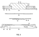
FIG. 2 is a sectional view of a part of the lamp device. -
FIG. 3 is a perspective view of a decomposed state of the lamp device. -
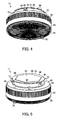
FIG. 4 is a perspective view of the lamp device. -
FIG. 5 is a perspective view of the lamp device. -
FIG. 6 is a sectional view of a luminaire using the lamp device. - In general, according to one embodiment, a lamp device includes a housing, a light-emitting module, a lighting device, a thermal radiator and an attachment base. The housing includes an opening part at one end side, a closing part at the other end side and an insertion part formed at a center of the closing part. The light-emitting module is arranged in the housing to emit light from the opening part. The lighting device is arranged to be closer to the closing part side than the light-emitting module in the housing, and includes a circuit board arranged around the insertion part. The thermal radiator includes a support part inserted through the insertion part, a light-emitting module connection part which is provided at one end side of the support part and to which the light-emitting module is thermally conductively connected, and an external thermal radiation part provided at the other end side of the support part. The attachment base is made of an insulating material and is arranged around the light-emitting module connection part. An attachment surface facing the light-emitting module is provided at one end side of the attachment base, and the light-emitting module connection part protrudes from the attachment surface. The attachment base supports the light-emitting module connected to the light-emitting module connection part, and is thermally connected thereto.
- As stated above, the insulating attachment base is arranged around the light-emitting module connection part of the thermal radiator. Thus, the light-emitting module can be attached, and insulation properties against the lighting device can be secured. Further, since the light-emitting module connection part protrudes from the attachment base, the light-emitting module certainly contacts the light-emitting module connection part, and excellent thermal radiation properties can be secured.
- Hereinafter, an embodiment will be described with reference to
FIG. 1 to FIG. 6 . - As shown in
FIG. 6 , a luminaire 10 is an embedded-type luminaire such as a downlight. Theluminaire 10 includes aflat lamp device 11, and anequipment device 12 on which thelamp device 11 is detachably and attachably mounted. - As shown in
FIG. 1 to FIG. 5 , thelamp device 11 includes ahousing 20, athermal radiator 21, anattachment base 22, a light-emitting module 23, areflector 24, alighting device 25 and atranslucent cover 26. Incidentally, in the following description, one end side of thelamp device 11, which is a light irradiation side, is a lower side, and the other end side thereof, which is an opposite side to the light irradiation direction, is an upper side. - The
housing 20 is formed of an insulating material, such as synthetic resin, into a cylindrical shape, and includes aperipheral part 28, anopening part 29 at the lower side of theperipheral part 28, and a closedpart 30 at the upper side of theperipheral part 28. Acylindrical insertion part 32 forming aninsertion port 31 opened in an up-and-down direction is protrudingly provided at the center of theclosing part 30 in thehousing 20. Anannular protrusion 33 to which thethermal radiator 21 is attached is upward protrudingly provided between the peripheral part of theclosing part 30 and theinsertion part 32. A circuitboard placing part 34 on which the lighting device 25 (circuit board 70) is positioned and placed is formed inside thehousing 20 and at the peripheral part of theclosing part 30 and the outer peripheral part of theinsertion part 32. Further, alocking part 35 to lock the lighting device 25 (the circuit board 70) is provided between the outer peripheral part of theinsertion part 32 and the circuitboard placing part 34. - Besides, the
thermal radiator 21 is integrally formed of a metal material such as aluminum die cast. Thethermal radiator 21 includes acylindrical support part 37, a light-emittingmodule connection part 38 formed at the lower side of thesupport part 37, and an externalthermal radiation part 39 formed at the upper side of thesupport part 37. - A
columnar part 40 insertable into theinsertion part 32 is formed at the lower side of thesupport part 37, and astep part 41 is formed around the lower periphery of thecolumnar part 40. Ataper part 42 whose sectional area increases toward the upper externalthermal radiation part 39 is formed at the upper side of thesupport part 37. An inclination angle of thetaper part 42 is set to, for example, 45°. - The light-emitting
module connection part 38 is a circular contact surface formed to be flat on the tip surface of thesupport part 37, and an area thereof is smaller than a sectional area of thesupport part 37 and is smaller than an area of the externalthermal radiation part 39. - The external
thermal radiation part 39 is formed into a disk shape larger than thesupport part 37 and the light-emittingmodule connection part 38, and is arranged on theprotrusion 33 in a state where the peripheral part protrudes from theprotrusion 33 in an outer diameter direction. A plurality ofkey grooves 44 and a plurality ofkeys 45 are disposed at specified positions on the peripheral part of the externalthermal radiation part 39. A thermalconductive sheet 46 is attached to the upper surface of the externalthermal radiation part 39. - A plurality of
bosses 47 for screwing theattachment base 22 is provided around thesupport part 37, and a plurality ofbosses 48 for screwing to thehousing 20 is provided on the peripheral part of theexternal connection part 39. A plurality ofscrews 49 is screwed to the plurality ofbosses 48 of thethermal radiator 21 from the inside of thehousing 20, so that thehousing 20 and thethermal radiator 21 are fixed. - A
cap part 50 having a specified standard size is constructed of the upper side including theprotrusion 33 of thehousing 20, the externalthermal radiation part 39 of thethermal radiator 21 and the like. - The
attachment base 22 is made of an insulating material such as synthetic resin. Ahole part 52 through which the light-emittingmodule connection part 38 is inserted is formed at the center of theattachment base 22. A plurality ofattachment holes 53 for screwing to thethermal radiator 21 is formed in the peripheral part of theattachment base 22, and a plurality ofattachment holes 54 for screwing thereflector 24 is formed. In a state where the light-emittingmodule connection part 38 is inserted through thehole part 52, and theattachment base 22 is arranged around the light-emittingmodule connection part 38, a plurality ofscrews 55 is screwed to the plurality ofbosses 47 of thethermal radiator 21 from theattachment holes 53, so that the attachment base is fixed to thethermal radiator 21. In the state where theattachment base 22 is fixed to thethermal radiator 21, the light-emittingmodule connection part 38 protrudes from anattachment surface 22a of theattachment base 22. A protrusion amount h of the light-emittingmodule connection part 38 from theattachment surface 22a of theattachment base 22 is small, and is preferably smaller than, for example, the thickness of aboard 58 of the light-emitting module 23. - The light-
emitting module 23 includes a plurality of light-emitting elements 57, and theboard 58 on which the plurality of light-emitting elements 57 are mounted. - For example, an SMD (Surface Mount Device) package is used for the light-
emitting elements 57. The light-emitting elements 57 are closely arranged on theboard 58 in an arbitrary arrangement. Incidentally, a COB (Chip On Board) system in which a plurality of LED chips is mounted on theboard 58 and is integrally sealed with sealing resin containing phosphor may be used for the light-emitting elements 57, or another semiconductor light-emitting element such as an EL element may be used. - The
board 58 is made of a material such as, for example, metal, ceramic or resin having excellent thermal conductivity. A pattern for electrically connecting the light-emittingelements 57 is formed on the mount surface of theboard 58 on which the light-emittingelements 57 are mounted. Aconnector 59 for electrically connecting thelighting device 25 is mounted on the pattern of theboard 58. - The back side of the
board 58 of the light-emittingmodule 23 is arranged to contact the light-emittingmodule connection part 38 and theattachment base 22 through an insulatingsheet 60 which is also a heat conductive sheet. The plural light-emittingelements 57 are arranged in a region of the light-emittingmodule connection part 38 when viewed from below. - The insulating
sheet 60 has heat conductivity and insulation properties as well as elasticity, and is formed to be larger than the light-emittingmodule connection part 38 and theboard 58. When the insulatingsheet 60 is sandwiched between the light-emittingmodule connection part 38 and theboard 58 and between theattachment base 22 and theboard 58, a step difference between the light-emittingmodule connection part 38 and theattachment base 22 is absorbed by a difference in compression amount of the insulatingsheet 60, and the application of stress to the light-emittingmodule 23 is relieved. - The
reflector 24 is made of an insulating material such as synthetic resin. Awindow hole 62 which is smaller than the outer shape of theboard 58 and through which the light-emittingelements 57 can be inserted is formed at the center of thereflector 24. A recessedpositioning part 63 in which theboard 58 is fitted to be positioned is formed on the upper surface of thereflector 24. A reflectingsurface 64 expanding downward from the peripheral edge part of thewindow hole 62 to the peripheral part of thereflector 24 is formed. A plurality ofsupport pieces 65 supported by thehousing 20 is provided at the peripheral part of thereflector 24. A plurality of attachment holes 66 for screwing thereflector 24 to theattachment base 22 is formed in the reflectingsurface 64. -
Screws 67 inserted through the attachment holes 66 are screwed and fastened to the attachment holes 54 of theattachment base 22, so that theboard 58 is held in the state where the board is pressed to the light-emittingmodule connection part 38. At this time, the insulatingsheet 60 sandwiched between the light-emittingmodule connection part 38 and theboard 58 and between theattachment base 22 and theboard 58 is compressed. Thus, the step difference between the light-emittingmodule connection part 38 and theattachment base 22 is absorbed by the difference in compression amount of the insulatingsheet 60, and the application of stress to the light-emittingmodule 23 is relieved. Thereflector 24 is arranged between the openingpart 29 of thehousing 20 and the light-emittingmodule 23, and covers thelighting device 25 so that light of the light-emittingelements 57 is not irradiated to thelighting device 25. - The
lighting device 25 includes, for example, a power supply circuit to rectify and smooth commercial AC power and to convert into DC power, a DC/DC converter to supply the DC power as specified DC output to the LED elements by switching of a switching element and to light the LED elements, and a control IC to control the oscillation of the switching element. In the case of the dimminglighting device 25, a function is provided in which a current of the light-emittingelement 57 is detected and is compared with a reference value corresponding to a dimming signal, and the control IC controls the switching operation of the switching element. - The
lighting device 25 includes thecircuit board 70 andcircuit parts 71 as a plurality of electronic parts mounted on thecircuit board 70. - The
circuit board 70 is formed into an annular shape, and a circularfitting hole 72 through which theinsertion part 32 of thehousing 20 is inserted is formed at the center of thecircuit board 70. A lower surface of thecircuit board 70 is amount surface 70a on which a lead part having a lead wire among thecircuit parts 71 is mounted. An upper surface thereof is awiring surface 70b as a wiring pattern surface or a solder surface provided with a wiring pattern to which the lead wire of the lead part is connected by soldering and on which a surface mount part among thecircuit parts 71 is mounted. - The
circuit board 70 is arranged at the upper position in thehousing 20 in a state where thewiring surface 70b is directed upward and faces the closingpart 30 of thehousing 20. Thecircuit parts 71 mounted on themount surface 70a of thecircuit board 70 is arranged among theperipheral part 28 of thehousing 20, theinsertion part 32, theattachment base 22 and thereflector 24. - A power input side of the
circuit board 70 is electrically connected to a pair of lamp pins 73 for power supply, and a lighting output side is electrically connected to the light-emittingmodule 23. The pair of lamp pins 73 for power supply protrudes vertically from the closingpart 30 of thehousing 20. Incidentally, in the case of the dimminglighting device 25, in addition to the lamp pins for power supply, a plurality of lamp pins 73 for dimming also protrudes vertically from the closingpart 30 of thehousing 20. - The
translucent cover 26 is formed into a disk shape from a synthetic resin having translucency, and is attached to thehousing 20 so as to cover theopening part 29. AFresnel lens 75 for controlling the light emitted from thelamp device 11 to obtain a specified luminous intensity distribution is formed on the inner surface (upper surface) of thetranslucent cover 26 facing the light-emittingmodule 23. TheFresnel lens 75 has a saw-like sectional shape in the diameter direction and is formed concentrically. Afinger hook part 76 to facilitate the rotation operation of thelamp device 11 attached to and detached from the equipment device 12 (socket) is protrudingly provided at the lower surface peripheral part of thetranslucent cover 26. Incidentally, theFresnel lens 75 may not be provided on the inner surface of thetranslucent cover 26, and a diffusion surface to diffuse light may be provided. - Next, as shown in
FIG. 6 , theequipment device 12 includes anequipment reflector 81 expanded and opened downward, an equipmentthermal radiator 82 as an equipment body attached to an upper part of theequipment reflector 81, asocket 83 attached to a lower part of the equipmentthermal radiator 82, aterminal base 85 attached to an upper part of the equipmentthermal radiator 82 by anattachment plate 84, and a plurality of attachment springs for ceiling attachment attached to the periphery of the equipmentthermal radiator 82. - The
equipment reflector 81 is formed into a cylindrical shape expanding downward. - The equipment
thermal radiator 82 is made of a material, for example, metal such as aluminum die cast, ceramic, or resin having excellent thermal radiation properties. The equipmentthermal radiator 82 includes a disk-shapedbase part 87, and a plurality of thermal radiation fins 88 protruding from an upper surface of thebase part 87. Aflat contact surface 89 exposed in theequipment reflector 81 is formed on a lower surface of thebase part 87. - The
socket 83 includes asocket body 91 formed into an annular shape from an insulating synthetic resin, and a not-shown pair of terminals for power supply arranged in thesocket body 91. Incidentally, when dimming is supported, a plurality of terminals for dimming is also provided. - A
circular insertion hole 92 through which the cap part 50 (protrusion 33) of thelamp device 11 is inserted is formed at the center of thesocket body 91. A plurality of connection holes through which the lamp pins 73 of thelamp device 11 are inserted is formed into a long hole shape along the circumferential direction on a lower surface of thesocket body 91. Terminals are arranged on upper sides of the respective connection holes, and the lamp pins 73 of thelamp device 11 inserted in the connection holes are electrically connected to the terminals. - A plurality of keys is protrudingly formed on the inner peripheral surface of the
socket body 91, and a plurality of substantially L-shaped key grooves is formed. The keys and the key grooves of thesocket 83 and thekey grooves 44 and thekeys 45 of thelamp device 11 are respectively provided at corresponding positions. Thekeys 45 and thekey grooves 44 of thelamp device 11 are matched with the key grooves and the keys of thesocket 83, thecap part 50 of thelamp device 11 is inserted in thesocket 83, and thelamp device 11 is rotated, so that thelamp device 11 can be detachably and attachably mounted on thesocket 83. - The
socket 83 is supported to the equipmentthermal radiator 82 by a support mechanism. In the support mechanism, thecap part 50 of thelamp device 11 is mounted on thesocket 83, so that the upper surface of thecap part 50, that is, the externalthermal radiation part 39 of thethermal radiator 21 is pressed to thecontact surface 89 of the equipmentthermal radiator 82 and the thermal conductivity is improved. - The
attachment base 85 is electrically connected to the terminal of thesocket 83. - In the
luminaire 10 including thelamp device 11 and theequipment device 12 as stated above, in order to mount thelamp device 11 on theequipment device 12, thekeys 45 and thekey grooves 44 of thecap part 50 are matched with the key grooves and the key of thesocket 83, thecap part 50 is inserted in thesocket 83, and thelamp device 11 is rotated by a specified angle with respect to thesocket 83. As a result, thekeys 45 of thecap part 50 are locked by the key grooves of thesocket 83, and thelamp device 11 can be attached to thesocket 83. By this, the lamp pins 73 of thecap part 50 are electrically connected to the respective terminals of thesocket 83. Besides, the upper surface of thecap part 50, that is, the externalthermal radiation part 39 of thethermal radiator 21 is pressed to and in close contact with thecontact surface 89 of the equipmentthermal radiator 82 through the thermalconductive sheet 46, and heat can be efficiently conducted from thethermal radiator 21 to the equipmentthermal radiator 82. - At the time of lighting of the
lamp device 11, commercial AC power is supplied to thelighting device 25 of thelamp device 11. Thelighting device 25 converts the commercial AC power into specified DC power and supplies the power to the light-emittingelements 57 of the light-emittingmodule 23, so that the light-emittingelements 57 are lit. The light of the lit light-emittingelements 57 passes through thetranslucent cover 26 and is irradiated to a specified irradiation direction. - In the
lamp device 11, since the light-emittingmodule 23 is arranged at the position close to thetranslucent cover 26 by thethermal radiator 21, most of the light of the light-emittingelements 57 is directly incident on thetranslucent cover 26 and is emitted, so that the light extraction efficiency can be improved. - Besides, at the time of lighting of the
lamp device 11, heat generated by the light-emittingelements 57 of the light-emittingmodule 23 is mainly conducted from theboard 58 to the light-emittingmodule connection part 38 of thethermal radiator 21, thesupport part 37 and the externalthermal radiation part 39 through the insulatingsheet 60. Further, the heat is conducted from the externalthermal radiation part 39 to the equipmentthermal radiator 82 through the heatconductive sheet 46, and is radiated to the air from the plurality of thermal radiation fins 88 of the equipmentthermal radiator 82. - At this time, since the light-emitting
module connection part 38 protrudes from theattachment surface 22a of theattachment base 22 to which the light-emittingmodule 23 is attached, theboard 58 of the light-emittingmodule 23 certainly contacts the light-emittingmodule connection part 38, and the heat generated by the light-emittingelements 57 is efficiently conducted from theboard 58 to the light-emittingmodule connection part 38. - Further, since the
support part 37 of thethermal radiator 21, the light-emittingmodule connection part 38 and the externalthermal radiation part 39 are integrally formed, the heat generated by the light-emittingelements 57 is efficiently conducted from the light-emittingmodule connection part 38 of thethermal radiator 21 to the externalthermal radiation part 39. - In general, heat has a characteristic of being radially conducted. Since the sectional area of the
support part 37 is increased from the light-emittingmodule connection part 38 toward the externalthermal radiation part 39, heat conduction loss at thesupport part 37 can be reduced. Thus, the heat generated by the light-emittingelements 57 of the light-emittingmodule 23 can be efficiently conducted from the light-emittingmodule connection part 38 to the externalthermal radiation part 39. - Accordingly, the heat generated by the light-emitting
elements 57 can be efficiently conducted to thethermal radiator 21, and the thermal radiation properties from the externalthermal radiation part 39 of thethermal radiator 21 can be improved. - Besides, at the time of lighting of the
lamp device 11, the heat generated by thelamp device 25 is conducted to thehousing 20 and the like, and is radiated to the air from the surface of thehousing 20 and the like. - In the
lamp device 11 of this embodiment, since the insulatingattachment base 22 is arranged around the light-emittingmodule connection part 38 of thethermal radiator 21, the peripheral part of the light-emittingmodule 23 connected to the light-emittingmodule connection part 38 can be stably supported, and insulation properties against thelighting device 25 can be secured. Further, since the light-emittingmodule connection part 38 protrudes from theattachment surface 22a of theattachment base 22, the light-emittingmodule 23 certainly contacts the light-emittingmodule connection part 38, and excellent thermal radiation properties can be secured. - Further, since the
attachment base 22 is formed of insulating material, theattachment base 22 and thecircuit parts 71 of thelighting device 25 can be arranged to be close to each other, and thelamp device 11 can be miniaturized. - Besides, the insulating
sheet 60 intervenes between the light-emittingmodule connection part 38 and the light-emittingmodule 23 and between theattachment base 22 and the light-emittingmodule 23. Thus, the step difference between the light-emittingmodule connection part 38 and theattachment base 22 is absorbed by the difference in compression amount of the insulatingsheet 60, and the application of stress to the light-emittingmodule 23 can be relieved. - Besides, since the
reflector 24 is arranged between the openingpart 29 of thehousing 20 and the light-emittingmodule 23, thereflector 24 reflects the light of the light-emittingelements 57 to the irradiation direction, and the light extraction efficiency can be improved. Further, since thereflector 24 covers thelighting device 25, the light of the light-emittingelements 57 can be prevented from being irradiated to thecircuit board 70 of thelighting device 25 and thecircuit parts 71, and light deterioration of thecircuit board 70 and thecircuit parts 71 can be prevented. Further, theboard 58 can be held between thereflector 24 and theattachment base 22. Accordingly, thereflector 24 has the three functions, that is, the reflection function, the protection function of thelighting device 25 and the fixing function of the light-emittingmodule 23. - Incidentally, since the
attachment base 22 is made of the insulating material having excellent heat conductivity, the heat generated by the light-emittingelements 57 can be efficiently conducted from theboard 58 to thethermal radiator 21 through theattachment base 22, and the thermal radiation properties can be improved. - While certain embodiments have been described, these embodiments have been presented by way of example only, and are not intended to limit the scope of the inventions. Indeed, the novel embodiments described herein may be embodied in a variety of other forms; furthermore, various omissions, substitutions and changes in the form of the embodiments described herein may be made without departing from the spirit of the inventions. The accompanying claims and their equivalents are intended to cover such forms or modifications as would fall within the scope and spirit of the inventions.
Claims (4)
- A lamp device (11) comprising:a housing (20) including an opening part (29) at one end side, a closing part (30) at the other end side and an insertion part (32) formed at a center of the closing part (30);a light-emitting module (23) arranged in the housing (20) so as to emit light from the opening part (29);a lighting device (25) arranged to be closer to the closing part (30) side than the light-emitting module (23) in the housing (20) and including a circuit board (70) arranged around the insertion part (32);a thermal radiator (21) including a support part (37) inserted through the insertion part (32), a light-emitting module connection part (38) which is provided at one end side of the support part (37) and to which the light-emitting module (23) is thermally conductively connected, and a thermal radiator (21) provided at the other end side of the support part (37) and including an external thermal radiation part (39); andan attachment base (22) which is made of an insulating material, is arranged around the light-emitting module connection part (38), is provided with an attachment surface (22a) facing the light-emitting module (23) at one end side, and supports the light-emitting module (23) connected to the light-emitting module connection part (38) which protrudes from the attachment surface (22a).
- The device (11) according to claim 1, further comprising an insulating sheet (60) intervening between the light-emitting module connection part (38) and the light-emitting module (23) and between the attachment base (22) and the light-emitting module (23).
- The device (11) according to claim 1 or 2, further comprising a reflector (24) which is arranged between the opening part (29) of the housing (20) and the light-emitting module (23), and holds the light-emitting module (23) between itself and the attachment base (22).
- A luminaire (10) comprising:the lamp device (11) according to any one of claims 1 to 3; andan equipment device (12) including a socket (83) to which the lamp device (11) is connected.
Applications Claiming Priority (1)
| Application Number | Priority Date | Filing Date | Title |
|---|---|---|---|
| JP2013195744A JP6197996B2 (en) | 2013-09-20 | 2013-09-20 | Lamp apparatus and lighting apparatus |
Publications (1)
| Publication Number | Publication Date |
|---|---|
| EP2851607A1 true EP2851607A1 (en) | 2015-03-25 |
Family
ID=50239414
Family Applications (1)
| Application Number | Title | Priority Date | Filing Date |
|---|---|---|---|
| EP14157902.9A Withdrawn EP2851607A1 (en) | 2013-09-20 | 2014-03-05 | Lamp device and luminaire |
Country Status (4)
| Country | Link |
|---|---|
| US (1) | US20150085486A1 (en) |
| EP (1) | EP2851607A1 (en) |
| JP (1) | JP6197996B2 (en) |
| CN (1) | CN203836645U (en) |
Families Citing this family (3)
| Publication number | Priority date | Publication date | Assignee | Title |
|---|---|---|---|---|
| CN104359032B (en) * | 2014-11-19 | 2017-01-18 | 西安重装渭南光电科技有限公司 | Integrated LED (Light Emitting Diode) light module with auxiliary heat radiator and assembling method of integrated LED light module |
| JP7018751B2 (en) * | 2017-12-07 | 2022-02-14 | 三菱電機株式会社 | lighting equipment |
| US11415737B2 (en) * | 2021-01-05 | 2022-08-16 | TieJun Wang | Cover for glass light guide plate |
Citations (2)
| Publication number | Priority date | Publication date | Assignee | Title |
|---|---|---|---|---|
| EP2461094A2 (en) * | 2010-12-03 | 2012-06-06 | Samsung LED Co., Ltd. | Light source for illumination apparatus and method of manufacturing the same |
| WO2013046341A1 (en) * | 2011-09-27 | 2013-04-04 | 東芝ライテック株式会社 | Lamp device and illumination device |
Family Cites Families (3)
| Publication number | Priority date | Publication date | Assignee | Title |
|---|---|---|---|---|
| MX2010002830A (en) * | 2007-09-12 | 2010-08-10 | Dialight Corp | Compact omnidirectional led light. |
| WO2011141846A2 (en) * | 2010-05-11 | 2011-11-17 | Koninklijke Philips Electronics N.V. | Lighting module |
| JP5655950B2 (en) * | 2011-09-27 | 2015-01-21 | 東芝ライテック株式会社 | Lamps and lighting fixtures |
-
2013
- 2013-09-20 JP JP2013195744A patent/JP6197996B2/en not_active Expired - Fee Related
-
2014
- 2014-03-05 EP EP14157902.9A patent/EP2851607A1/en not_active Withdrawn
- 2014-03-12 US US14/206,285 patent/US20150085486A1/en not_active Abandoned
- 2014-03-19 CN CN201420125727.8U patent/CN203836645U/en not_active Expired - Fee Related
Patent Citations (2)
| Publication number | Priority date | Publication date | Assignee | Title |
|---|---|---|---|---|
| EP2461094A2 (en) * | 2010-12-03 | 2012-06-06 | Samsung LED Co., Ltd. | Light source for illumination apparatus and method of manufacturing the same |
| WO2013046341A1 (en) * | 2011-09-27 | 2013-04-04 | 東芝ライテック株式会社 | Lamp device and illumination device |
Also Published As
| Publication number | Publication date |
|---|---|
| JP2015060808A (en) | 2015-03-30 |
| US20150085486A1 (en) | 2015-03-26 |
| JP6197996B2 (en) | 2017-09-20 |
| CN203836645U (en) | 2014-09-17 |
Similar Documents
| Publication | Publication Date | Title |
|---|---|---|
| US8764249B2 (en) | Lamp device and luminaire | |
| CN102466162B (en) | Lamp unit and lighting fixture | |
| CN102466161B (en) | Lamp unit and lighting fixture | |
| JP4854798B2 (en) | Lighting device | |
| EP2532948B1 (en) | Lamp device | |
| CN104246353B (en) | Lamp and lighting device | |
| EP2423573A2 (en) | Lamp unit and illumination apparatus | |
| EP2868961A1 (en) | Lighting apparatus | |
| CN204829426U (en) | Lamp device and lighting device | |
| JP2013077493A (en) | Led lighting device | |
| CN102109114A (en) | Bulb-shaped lamp and lighting fixture | |
| EP2851607A1 (en) | Lamp device and luminaire | |
| US20140169004A1 (en) | Lamp Device and Luminaire | |
| EP2808603A1 (en) | Lamp device and luminaire | |
| JP2013008582A (en) | Lamp device | |
| JP2016134292A (en) | Lamp device and illuminating device | |
| JP5679111B2 (en) | Lamp apparatus and lighting apparatus | |
| CN204062609U (en) | Lamp device and lighting device | |
| JP2014071992A (en) | Lamp device and lighting fixture | |
| JP2012079498A (en) | Light-emitting device and lighting fixture | |
| CN203744049U (en) | Lighting device | |
| CN203892916U (en) | Light source | |
| JP5582365B2 (en) | Lighting device |
Legal Events
| Date | Code | Title | Description |
|---|---|---|---|
| PUAI | Public reference made under article 153(3) epc to a published international application that has entered the european phase |
Free format text: ORIGINAL CODE: 0009012 |
|
| 17P | Request for examination filed |
Effective date: 20140305 |
|
| AK | Designated contracting states |
Kind code of ref document: A1 Designated state(s): AL AT BE BG CH CY CZ DE DK EE ES FI FR GB GR HR HU IE IS IT LI LT LU LV MC MK MT NL NO PL PT RO RS SE SI SK SM TR |
|
| AX | Request for extension of the european patent |
Extension state: BA ME |
|
| STAA | Information on the status of an ep patent application or granted ep patent |
Free format text: STATUS: THE APPLICATION IS DEEMED TO BE WITHDRAWN |
|
| 18D | Application deemed to be withdrawn |
Effective date: 20150926 |