EP2851269A1 - Steering system assembly for commercial vehicles and commercial vehicle comprising the steering system assembly - Google Patents
Steering system assembly for commercial vehicles and commercial vehicle comprising the steering system assembly Download PDFInfo
- Publication number
- EP2851269A1 EP2851269A1 EP14185920.7A EP14185920A EP2851269A1 EP 2851269 A1 EP2851269 A1 EP 2851269A1 EP 14185920 A EP14185920 A EP 14185920A EP 2851269 A1 EP2851269 A1 EP 2851269A1
- Authority
- EP
- European Patent Office
- Prior art keywords
- steering
- arm
- power steering
- leverages
- tie rod
- Prior art date
- Legal status (The legal status is an assumption and is not a legal conclusion. Google has not performed a legal analysis and makes no representation as to the accuracy of the status listed.)
- Granted
Links
Images


Classifications
-
- B—PERFORMING OPERATIONS; TRANSPORTING
- B62—LAND VEHICLES FOR TRAVELLING OTHERWISE THAN ON RAILS
- B62D—MOTOR VEHICLES; TRAILERS
- B62D7/00—Steering linkage; Stub axles or their mountings
- B62D7/06—Steering linkage; Stub axles or their mountings for individually-pivoted wheels, e.g. on king-pins
- B62D7/08—Steering linkage; Stub axles or their mountings for individually-pivoted wheels, e.g. on king-pins the pivotal axes being situated in a single plane transverse to the longitudinal centre line of the vehicle
Landscapes
- Engineering & Computer Science (AREA)
- Chemical & Material Sciences (AREA)
- Combustion & Propulsion (AREA)
- Transportation (AREA)
- Mechanical Engineering (AREA)
- Steering-Linkage Mechanisms And Four-Wheel Steering (AREA)
- Steering Controls (AREA)
Abstract
Description
- The present invention relates to a steering system assembly for commercial vehicles and to a commercial vehicle comprising the steering system assembly.
- The known commercial vehicles having one front steering axle have the steering power disposed in a front position - according to a travelling direction of the vehicle - with respect to the steering axle. Usually the hydraulic power steering is positioned substantially at the end of one of the side members of the vehicle. Several leverages connected with the swinging arm of the hydraulic power steering command the axle tie rod, which command the turning of the wheel spindles.
- In order to avoid the interference of the power steering with the wheels, the power steering is arranged as far as possible from the steering axle.
- However, for vehicles not really long enough it is not possible to avoid such interference.
- Therefore it is the main object of the present invention to provide a steering system assembly for commercial vehicles, which overcomes the above problems/drawbacks.
- The main principle of the invention is to arrange the power steering substantially over the steering axle of the vehicle so as the wheels can turn around it without they interfere with the steering wheels themselves.
- The further leverages that, of course, are necessary to transmit the steering motion to the steering axle can be position indifferently in front or in rear position with respect to the power steering.
- Advantageously, thanks to the present invention it is possible to reach the theoretical 50 degree of wheel cut.
- Another object of the present invention is a ground vehicle provided with only one, preferably front, steering axle provided with the above steering system assembly.
- These and further objects are achieved by means of a steering systems and a commercial vehicle comprising the steering system as described in the attached claims, which form an integral part of the present description.
- The invention will become fully clear from the following detailed description, given by way of a mere exemplifying and non limiting example, to be read with reference to the attached drawing figures, wherein:
-
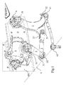
Fig. 1 shows a perspective view of the steering system assembly according to the present invention; -
Figs. 2 and 2a , show a frontal view of one component of the steering system offigure 1 and a respective right side view of such component; -
Fig. 3 shows an exploded perspective view of steering system offigure 1 . - The same reference numerals and letters in the figures designate the same or functionally equivalent parts.
-
Figure 1 of the present invention shows a perspective view of the steering assembly of the present invention.
Even if the steering axle is not shown, a dashed axis S schematizes the steering axle and, in particular, its centre line, which is transversal with respect to the elongated direction indicated by the side member SM. - Over such axis S is arranged the
power steering 1, that can be hydraulic or electric or of further nature. - The
power steering 1 has a swingingarm 5 having twoopposite ends first end 51 has its fulcrum on thepower steering 1, where it pivots for defining its swinging motion; the second end is rotatably joined with atie rod 2 for transferring the steering motion to asteering idler arm 3.
Thesteering idler arm 3 has three connection points: afirst point 31, corresponding with its upper end, is rotatably associated with the same side member SM, which supports thepower steering 1; asecond point 32, corresponding with its lower end, is connected with the steering tie rod 4; athird point 33, indicating an intermediate portion of theidler arm 3, is connected with thetie rod 2 hinged on theswinging arm 5.
About the steering tie rod 4, itsfirst end 41 is hinged on thesteering idler arm 3, while the second andopposite end 42, with respect to thefirst end 41, is suitable to be connected to the spindle of the wheel (partially shown onfigure 3 ). The spindle of the wheel, as usual, lies in a first vertical plane where lies also the axis S.
By thefigure 1 , it is clear that thesecond end 41 falls under thepower steering 1, and in particular, according to a preferred embodiment, under (vertically under) thefulcrum 51 of theswinging arm 5.
In the context of the present description "over" or "under" shall be interpreted as "vertically over" according to a vertical direction, perpendicular with respect to the horizontal direction defined by the side member SM offigure 1 .
In other words "over" means "over and substantially at", and "under" means "under and substantially at".
This aspect is clear also by the fact that theend 42 is suitable to be connected with the wheel spindle, that is operatively in a lower position with respect to the side member SM.
In the context of the present description, "front" shall be interpreted according to the front travelling of the vehicle. The front direction is indicated onfigure 1 by means of a thick arrow on the right of the figure.
At least theleverages
The set of thecomponents
The steering idler arm can be placed in front or in the rear of thepower steering 1 in a symmetric way with respect to the view onfigure 1 . In order to understand this further, symmetric arrangement - with respect to the one shown through the figures - it is sufficient to revert the thick arrow on the right offigure 1 .
According to a preferred embodiment of the present invention, the swingingarm 5 is external with respect to the reciprocal disposition of the power steering on the side member SM. Therefore, thefirst end 31 of theidler arm 3 is hinged on the side member SM by means of spacing means 6.
In order to avoid an excessive stress on the spacing means 6, theidler arm 3 is preferably not flat, but theopposite ends second end 32 tends to protrude externally with respect to the side member SM. This is particularly clear fromfig. 2a .
Onfigure 3 is shown an exploded view of the steering system. The arm SP of the spindle (not shown) of a wheel is shown connected with theend 42 of the steering tie rod 4.
Fromfigure 3 it is possible also to appreciate that theswinging arm 5 is slightly bend along its development toward the side member SM.
Moreover, fromfigure 3 it is well shown an embodiment of thetie rod 2 having theend 22, suitably to be connected with theidler arm 3, shaped as a fork.
Thetie rod 2 is really short in order to have the power steering 1 and theidler arm 3 close together.
The half-moon shape of theidler arm 3 helps in this sense, namely, in order to arrange thepower steering 1 and theidler arm 3 close together, by leaving free space for the wheel rotation.
In addition, it is preferred that theidler arm 3 is curved as an "half moon" with its hump facing theswinging arm 5. According to a preferred implementation of the invention, a commercial vehicle is provided with a just one front steering axle having the steering system as described above. - Many changes, modifications, variations and other uses and applications of the subject invention will become apparent to those skilled in the art after considering the specification and the accompanying drawings which disclose preferred embodiments thereof. All such changes, modifications, variations and other uses and applications which do not depart from the scope of the invention are deemed to be covered by this invention.
- Further implementation details will not be described, as the man skilled in the art is able to carry out the invention starting from the teaching of the above description.
Claims (15)
- Steering system assembly for commercial vehicles, the steering system comprising:- a steering axle (S),- a power steering (1),- leverages (2,3,4,5) to transmit the steering motion from the power steering (1) to a spindle arm (SP) of a steering wheel spindle of the steering axle,wherein the power steering (1) is arranged over the steering axle and substantially at the steering axles (S).
- Steering system according to claim 1, wherein said leverages (2,3,4,5) comprise a swinging arm (5) having a fulcrum (51) on the power steering (1) and wherein the spindle arm (SP) is arranged vertically under said fulcrum (51).
- Steering system according to one of the previous claims 1 or 2, wherein said leverages (2, 3, 4, 5) comprise an idler arm (3) connected to said swinging arm (5) through a tie rod (2) and to a spindle arm (SP) of a steering wheel spindle through a steering tie rod (4).
- Steering system according to claim 3, wherein said idler arm (3) has three connection points:- a first point (31), corresponding with its upper end, rotatably associated with a vehicle fixed element (SM) supporting the power steering (1);- a second point (32), corresponding with its lower end, is connected with the steering tie rod (4);- a third point (33), indicating an intermediate portion of the idler arm (3), connected with the tie rod (2) hinged on the swinging arm (5).
- Steering system according to claims 3 or 4, wherein said idler arm (3) is curved as a "half-moon" with its hump facing the swinging arm (5).
- Steering system according to claims 3 to 5, wherein said second end (32) of the idler arm (3) tends to protrude externally with respect to said vehicular fixed element (SM).
- Steering system according to any of the previous claims 3- 6, wherein said leverages (2, 3, 4) are disposed in front or in rear position with respect to the power steering (1).
- Commercial vehicle provided with a fixed element (SM), only one steering axle (S), a power steering (1), leverages (2, 3, 4, 5) to transmit the steering motion from the power steering (1) to a spindle arm (SP) of a steering wheel spindle of the steering axle, wherein the power steering (1) is arranged over the steering axle and substantially at the steering axles (S).
- Commercial vehicle according to claim 8, wherein said leverages (2, 3, 4, 5) comprise a swinging arm (5) having a fulcrum (51) on the power steering (1) and wherein the spindle arm (SP) is arranged vertically under said fulcrum (51).
- Commercial vehicle according to one of the previous claims 8 or 9, wherein said leverages (2, 3, 4, 5) comprise an idler arm (3) connected to said swinging arm (5) through a tie rod (2) and to a spindle arm (SP) of a steering wheel spindle through a steering tie rod (4).
- Commercial vehicle according to claim 10, wherein said idler arm (3) has three connection points:- a first point (31), corresponding with its upper end, rotatably associated with a vehicle fixed element (SM) supporting the power steering (1);- a second point (32), corresponding with its lower end, is connected with the steering tie rod (4);- a third point (33), indicating an intermediate portion of the idler arm (3), connected with the tie rod (2) hinged on the swinging arm (5).
- Commercial vehicle according to claims 10 or 11, wherein said idler arm (3) is curved as a "half-moon" with its hump facing the swinging arm (5).
- Commercial vehicle according to claims 10 to 12, wherein said second end (32) of the idler arm (3) tends to protrude externally with respect to said vehicular fixed element (SM).
- Commercial vehicle according to any of the previous claims 10 - 13, wherein said leverages (2, 3, 4) are disposed in front or in rear position with respect to the power steering (1) and a travelling direction.
- Commercial vehicle according to any of the previous claims 8 - 14, further comprising side members, defining a longitudinal development of the vehicle and said fixed element of the vehicle.
Applications Claiming Priority (1)
| Application Number | Priority Date | Filing Date | Title |
|---|---|---|---|
| IT001570A ITMI20131570A1 (en) | 2013-09-24 | 2013-09-24 | STEERING SYSTEM FOR COMMERCIAL VEHICLES AND TRADE VEHICLES INCLUDING THE STEERING SYSTEM |
Publications (2)
| Publication Number | Publication Date |
|---|---|
| EP2851269A1 true EP2851269A1 (en) | 2015-03-25 |
| EP2851269B1 EP2851269B1 (en) | 2016-11-02 |
Family
ID=49554383
Family Applications (1)
| Application Number | Title | Priority Date | Filing Date |
|---|---|---|---|
| EP14185920.7A Active EP2851269B1 (en) | 2013-09-24 | 2014-09-23 | Steering system assembly for commercial vehicles and commercial vehicle comprising the steering system assembly |
Country Status (4)
| Country | Link |
|---|---|
| EP (1) | EP2851269B1 (en) |
| AU (1) | AU2014233559B2 (en) |
| ES (1) | ES2612430T3 (en) |
| IT (1) | ITMI20131570A1 (en) |
Cited By (1)
| Publication number | Priority date | Publication date | Assignee | Title |
|---|---|---|---|---|
| EP3750782A1 (en) * | 2019-06-10 | 2020-12-16 | Iveco Magirus Ag | Improved rocker/lever arm assembly for a steering system of a vehicle |
Citations (2)
| Publication number | Priority date | Publication date | Assignee | Title |
|---|---|---|---|---|
| JPS5780364U (en) * | 1981-10-12 | 1982-05-18 | ||
| US4540059A (en) * | 1982-06-07 | 1985-09-10 | Nissan Motor Co., Ltd. | Vehicle steering system |
Family Cites Families (3)
| Publication number | Priority date | Publication date | Assignee | Title |
|---|---|---|---|---|
| DE3033863A1 (en) * | 1980-09-09 | 1982-04-29 | Bayer Ag, 5090 Leverkusen | NEW FLUORINE AND CHLORINE-METHYL-THIO-AMINO-BENZAMIDES, A METHOD FOR THEIR PRODUCTION AND THEIR USE |
| US6055853A (en) * | 1997-11-11 | 2000-05-02 | Navistar International Transportation Corp | Instrumented data acquisition system and steering wheel monitor for vehicle steering system |
| GB2363767B (en) * | 2000-06-23 | 2003-10-08 | Agco Gmbh & Co | Steering device especially for farming tractors & similar commercial vehicles |
-
2013
- 2013-09-24 IT IT001570A patent/ITMI20131570A1/en unknown
-
2014
- 2014-09-23 AU AU2014233559A patent/AU2014233559B2/en active Active
- 2014-09-23 EP EP14185920.7A patent/EP2851269B1/en active Active
- 2014-09-23 ES ES14185920.7T patent/ES2612430T3/en active Active
Patent Citations (2)
| Publication number | Priority date | Publication date | Assignee | Title |
|---|---|---|---|---|
| JPS5780364U (en) * | 1981-10-12 | 1982-05-18 | ||
| US4540059A (en) * | 1982-06-07 | 1985-09-10 | Nissan Motor Co., Ltd. | Vehicle steering system |
Cited By (1)
| Publication number | Priority date | Publication date | Assignee | Title |
|---|---|---|---|---|
| EP3750782A1 (en) * | 2019-06-10 | 2020-12-16 | Iveco Magirus Ag | Improved rocker/lever arm assembly for a steering system of a vehicle |
Also Published As
| Publication number | Publication date |
|---|---|
| ES2612430T3 (en) | 2017-05-16 |
| ITMI20131570A1 (en) | 2015-03-25 |
| AU2014233559A1 (en) | 2015-04-09 |
| AU2014233559B2 (en) | 2017-09-21 |
| EP2851269B1 (en) | 2016-11-02 |
Similar Documents
| Publication | Publication Date | Title |
|---|---|---|
| CN104703870B (en) | vehicle | |
| TWI530423B (en) | Vehicle | |
| JP6743566B2 (en) | Steer-by-wire steering system | |
| CA2898855C (en) | Auxiliary axle and suspension assembly | |
| US11267303B2 (en) | Suspension device and lower arm | |
| US9375992B2 (en) | Torsion beam axle device for vehicle | |
| CN106470862B (en) | For electric installation under the spring of wheel hub motor vehicle | |
| MX2019006407A (en) | Suspension group for motor vehicle, wheel group for motor vehicle, front end of a motor vehicle and motor vehicle thereof. | |
| US11241926B2 (en) | Suspension apparatus and vehicle | |
| JP5873891B2 (en) | Suspension coil spring and strut suspension system | |
| EP2851269B1 (en) | Steering system assembly for commercial vehicles and commercial vehicle comprising the steering system assembly | |
| CN104309429A (en) | Four-wheel environment-friendly electric vehicle | |
| CN109515088A (en) | Suspension control arm structure, suspension and vehicle | |
| JP2006175946A5 (en) | ||
| CN202022050U (en) | Installation structure of electric car front axle for fireworks factories | |
| KR20140006255A (en) | In-wheel motor housing integrated with multi-link suspension | |
| JP6372741B2 (en) | Stabilizer bar mounting structure | |
| US9902223B2 (en) | Couplable motor vehicle with improved coupling | |
| JP2013159188A (en) | Wire harness routing structure of steering wheel | |
| JP5617750B2 (en) | Vehicle suspension system | |
| CN209257809U (en) | Suspension control arm structure, suspension and vehicle | |
| EP3281813B1 (en) | Vehicle suspension assembly and vehicle | |
| CN207213620U (en) | Installation driving lever on the right side of a kind of automobile using | |
| FR3028477A1 (en) | MACPHERSON SUSPENSION SHOCK ABSORBER COMPRISING CLAMPING CAPS MODIFYING PARALLELIZED SPRAY | |
| JP2020104647A (en) | Vehicle rear part structure |
Legal Events
| Date | Code | Title | Description |
|---|---|---|---|
| PUAI | Public reference made under article 153(3) epc to a published international application that has entered the european phase |
Free format text: ORIGINAL CODE: 0009012 |
|
| 17P | Request for examination filed |
Effective date: 20140923 |
|
| AK | Designated contracting states |
Kind code of ref document: A1 Designated state(s): AL AT BE BG CH CY CZ DE DK EE ES FI FR GB GR HR HU IE IS IT LI LT LU LV MC MK MT NL NO PL PT RO RS SE SI SK SM TR |
|
| AX | Request for extension of the european patent |
Extension state: BA ME |
|
| R17P | Request for examination filed (corrected) |
Effective date: 20150928 |
|
| RBV | Designated contracting states (corrected) |
Designated state(s): AL AT BE BG CH CY CZ DE DK EE ES FI FR GB GR HR HU IE IS IT LI LT LU LV MC MK MT NL NO PL PT RO RS SE SI SK SM TR |
|
| GRAP | Despatch of communication of intention to grant a patent |
Free format text: ORIGINAL CODE: EPIDOSNIGR1 |
|
| INTG | Intention to grant announced |
Effective date: 20160422 |
|
| RIN1 | Information on inventor provided before grant (corrected) |
Inventor name: BLACK, NEIL |
|
| GRAS | Grant fee paid |
Free format text: ORIGINAL CODE: EPIDOSNIGR3 |
|
| GRAA | (expected) grant |
Free format text: ORIGINAL CODE: 0009210 |
|
| AK | Designated contracting states |
Kind code of ref document: B1 Designated state(s): AL AT BE BG CH CY CZ DE DK EE ES FI FR GB GR HR HU IE IS IT LI LT LU LV MC MK MT NL NO PL PT RO RS SE SI SK SM TR |
|
| REG | Reference to a national code |
Ref country code: GB Ref legal event code: FG4D |
|
| REG | Reference to a national code |
Ref country code: AT Ref legal event code: REF Ref document number: 841515 Country of ref document: AT Kind code of ref document: T Effective date: 20161115 Ref country code: CH Ref legal event code: EP |
|
| REG | Reference to a national code |
Ref country code: IE Ref legal event code: FG4D |
|
| REG | Reference to a national code |
Ref country code: DE Ref legal event code: R096 Ref document number: 602014004595 Country of ref document: DE |
|
| REG | Reference to a national code |
Ref country code: NL Ref legal event code: FP |
|
| REG | Reference to a national code |
Ref country code: SE Ref legal event code: TRGR |
|
| PG25 | Lapsed in a contracting state [announced via postgrant information from national office to epo] |
Ref country code: LV Free format text: LAPSE BECAUSE OF FAILURE TO SUBMIT A TRANSLATION OF THE DESCRIPTION OR TO PAY THE FEE WITHIN THE PRESCRIBED TIME-LIMIT Effective date: 20161102 |
|
| REG | Reference to a national code |
Ref country code: LT Ref legal event code: MG4D |
|
| REG | Reference to a national code |
Ref country code: AT Ref legal event code: MK05 Ref document number: 841515 Country of ref document: AT Kind code of ref document: T Effective date: 20161102 |
|
| PG25 | Lapsed in a contracting state [announced via postgrant information from national office to epo] |
Ref country code: GR Free format text: LAPSE BECAUSE OF FAILURE TO SUBMIT A TRANSLATION OF THE DESCRIPTION OR TO PAY THE FEE WITHIN THE PRESCRIBED TIME-LIMIT Effective date: 20170203 Ref country code: NO Free format text: LAPSE BECAUSE OF FAILURE TO SUBMIT A TRANSLATION OF THE DESCRIPTION OR TO PAY THE FEE WITHIN THE PRESCRIBED TIME-LIMIT Effective date: 20170202 Ref country code: LT Free format text: LAPSE BECAUSE OF FAILURE TO SUBMIT A TRANSLATION OF THE DESCRIPTION OR TO PAY THE FEE WITHIN THE PRESCRIBED TIME-LIMIT Effective date: 20161102 |
|
| REG | Reference to a national code |
Ref country code: ES Ref legal event code: FG2A Ref document number: 2612430 Country of ref document: ES Kind code of ref document: T3 Effective date: 20170516 |
|
| PG25 | Lapsed in a contracting state [announced via postgrant information from national office to epo] |
Ref country code: PT Free format text: LAPSE BECAUSE OF FAILURE TO SUBMIT A TRANSLATION OF THE DESCRIPTION OR TO PAY THE FEE WITHIN THE PRESCRIBED TIME-LIMIT Effective date: 20170302 Ref country code: AT Free format text: LAPSE BECAUSE OF FAILURE TO SUBMIT A TRANSLATION OF THE DESCRIPTION OR TO PAY THE FEE WITHIN THE PRESCRIBED TIME-LIMIT Effective date: 20161102 Ref country code: FI Free format text: LAPSE BECAUSE OF FAILURE TO SUBMIT A TRANSLATION OF THE DESCRIPTION OR TO PAY THE FEE WITHIN THE PRESCRIBED TIME-LIMIT Effective date: 20161102 Ref country code: HR Free format text: LAPSE BECAUSE OF FAILURE TO SUBMIT A TRANSLATION OF THE DESCRIPTION OR TO PAY THE FEE WITHIN THE PRESCRIBED TIME-LIMIT Effective date: 20161102 Ref country code: PL Free format text: LAPSE BECAUSE OF FAILURE TO SUBMIT A TRANSLATION OF THE DESCRIPTION OR TO PAY THE FEE WITHIN THE PRESCRIBED TIME-LIMIT Effective date: 20161102 Ref country code: IS Free format text: LAPSE BECAUSE OF FAILURE TO SUBMIT A TRANSLATION OF THE DESCRIPTION OR TO PAY THE FEE WITHIN THE PRESCRIBED TIME-LIMIT Effective date: 20170302 Ref country code: RS Free format text: LAPSE BECAUSE OF FAILURE TO SUBMIT A TRANSLATION OF THE DESCRIPTION OR TO PAY THE FEE WITHIN THE PRESCRIBED TIME-LIMIT Effective date: 20161102 |
|
| PG25 | Lapsed in a contracting state [announced via postgrant information from national office to epo] |
Ref country code: RO Free format text: LAPSE BECAUSE OF FAILURE TO SUBMIT A TRANSLATION OF THE DESCRIPTION OR TO PAY THE FEE WITHIN THE PRESCRIBED TIME-LIMIT Effective date: 20161102 Ref country code: DK Free format text: LAPSE BECAUSE OF FAILURE TO SUBMIT A TRANSLATION OF THE DESCRIPTION OR TO PAY THE FEE WITHIN THE PRESCRIBED TIME-LIMIT Effective date: 20161102 Ref country code: EE Free format text: LAPSE BECAUSE OF FAILURE TO SUBMIT A TRANSLATION OF THE DESCRIPTION OR TO PAY THE FEE WITHIN THE PRESCRIBED TIME-LIMIT Effective date: 20161102 Ref country code: CZ Free format text: LAPSE BECAUSE OF FAILURE TO SUBMIT A TRANSLATION OF THE DESCRIPTION OR TO PAY THE FEE WITHIN THE PRESCRIBED TIME-LIMIT Effective date: 20161102 Ref country code: SK Free format text: LAPSE BECAUSE OF FAILURE TO SUBMIT A TRANSLATION OF THE DESCRIPTION OR TO PAY THE FEE WITHIN THE PRESCRIBED TIME-LIMIT Effective date: 20161102 |
|
| REG | Reference to a national code |
Ref country code: DE Ref legal event code: R097 Ref document number: 602014004595 Country of ref document: DE |
|
| REG | Reference to a national code |
Ref country code: FR Ref legal event code: PLFP Year of fee payment: 4 |
|
| PG25 | Lapsed in a contracting state [announced via postgrant information from national office to epo] |
Ref country code: BE Free format text: LAPSE BECAUSE OF FAILURE TO SUBMIT A TRANSLATION OF THE DESCRIPTION OR TO PAY THE FEE WITHIN THE PRESCRIBED TIME-LIMIT Effective date: 20161102 Ref country code: BG Free format text: LAPSE BECAUSE OF FAILURE TO SUBMIT A TRANSLATION OF THE DESCRIPTION OR TO PAY THE FEE WITHIN THE PRESCRIBED TIME-LIMIT Effective date: 20170202 Ref country code: SM Free format text: LAPSE BECAUSE OF FAILURE TO SUBMIT A TRANSLATION OF THE DESCRIPTION OR TO PAY THE FEE WITHIN THE PRESCRIBED TIME-LIMIT Effective date: 20161102 |
|
| PLBE | No opposition filed within time limit |
Free format text: ORIGINAL CODE: 0009261 |
|
| STAA | Information on the status of an ep patent application or granted ep patent |
Free format text: STATUS: NO OPPOSITION FILED WITHIN TIME LIMIT |
|
| 26N | No opposition filed |
Effective date: 20170803 |
|
| PG25 | Lapsed in a contracting state [announced via postgrant information from national office to epo] |
Ref country code: SI Free format text: LAPSE BECAUSE OF FAILURE TO SUBMIT A TRANSLATION OF THE DESCRIPTION OR TO PAY THE FEE WITHIN THE PRESCRIBED TIME-LIMIT Effective date: 20161102 |
|
| REG | Reference to a national code |
Ref country code: CH Ref legal event code: PL |
|
| PG25 | Lapsed in a contracting state [announced via postgrant information from national office to epo] |
Ref country code: MC Free format text: LAPSE BECAUSE OF FAILURE TO SUBMIT A TRANSLATION OF THE DESCRIPTION OR TO PAY THE FEE WITHIN THE PRESCRIBED TIME-LIMIT Effective date: 20161102 |
|
| REG | Reference to a national code |
Ref country code: IE Ref legal event code: MM4A |
|
| PG25 | Lapsed in a contracting state [announced via postgrant information from national office to epo] |
Ref country code: LU Free format text: LAPSE BECAUSE OF NON-PAYMENT OF DUE FEES Effective date: 20170923 |
|
| PG25 | Lapsed in a contracting state [announced via postgrant information from national office to epo] |
Ref country code: IE Free format text: LAPSE BECAUSE OF NON-PAYMENT OF DUE FEES Effective date: 20170923 Ref country code: CH Free format text: LAPSE BECAUSE OF NON-PAYMENT OF DUE FEES Effective date: 20170930 Ref country code: LI Free format text: LAPSE BECAUSE OF NON-PAYMENT OF DUE FEES Effective date: 20170930 |
|
| REG | Reference to a national code |
Ref country code: FR Ref legal event code: PLFP Year of fee payment: 5 |
|
| PG25 | Lapsed in a contracting state [announced via postgrant information from national office to epo] |
Ref country code: MT Free format text: LAPSE BECAUSE OF NON-PAYMENT OF DUE FEES Effective date: 20170923 |
|
| PG25 | Lapsed in a contracting state [announced via postgrant information from national office to epo] |
Ref country code: HU Free format text: LAPSE BECAUSE OF FAILURE TO SUBMIT A TRANSLATION OF THE DESCRIPTION OR TO PAY THE FEE WITHIN THE PRESCRIBED TIME-LIMIT; INVALID AB INITIO Effective date: 20140923 |
|
| PG25 | Lapsed in a contracting state [announced via postgrant information from national office to epo] |
Ref country code: CY Free format text: LAPSE BECAUSE OF FAILURE TO SUBMIT A TRANSLATION OF THE DESCRIPTION OR TO PAY THE FEE WITHIN THE PRESCRIBED TIME-LIMIT Effective date: 20161102 |
|
| PG25 | Lapsed in a contracting state [announced via postgrant information from national office to epo] |
Ref country code: MK Free format text: LAPSE BECAUSE OF FAILURE TO SUBMIT A TRANSLATION OF THE DESCRIPTION OR TO PAY THE FEE WITHIN THE PRESCRIBED TIME-LIMIT Effective date: 20161102 |
|
| PG25 | Lapsed in a contracting state [announced via postgrant information from national office to epo] |
Ref country code: TR Free format text: LAPSE BECAUSE OF FAILURE TO SUBMIT A TRANSLATION OF THE DESCRIPTION OR TO PAY THE FEE WITHIN THE PRESCRIBED TIME-LIMIT Effective date: 20161102 |
|
| PG25 | Lapsed in a contracting state [announced via postgrant information from national office to epo] |
Ref country code: AL Free format text: LAPSE BECAUSE OF FAILURE TO SUBMIT A TRANSLATION OF THE DESCRIPTION OR TO PAY THE FEE WITHIN THE PRESCRIBED TIME-LIMIT Effective date: 20161102 |
|
| P01 | Opt-out of the competence of the unified patent court (upc) registered |
Effective date: 20230523 |
|
| PGFP | Annual fee paid to national office [announced via postgrant information from national office to epo] |
Ref country code: DE Payment date: 20250926 Year of fee payment: 12 |
|
| PGFP | Annual fee paid to national office [announced via postgrant information from national office to epo] |
Ref country code: NL Payment date: 20250925 Year of fee payment: 12 Ref country code: IT Payment date: 20250909 Year of fee payment: 12 |
|
| PGFP | Annual fee paid to national office [announced via postgrant information from national office to epo] |
Ref country code: GB Payment date: 20250923 Year of fee payment: 12 |
|
| PGFP | Annual fee paid to national office [announced via postgrant information from national office to epo] |
Ref country code: FR Payment date: 20250925 Year of fee payment: 12 |
|
| PGFP | Annual fee paid to national office [announced via postgrant information from national office to epo] |
Ref country code: SE Payment date: 20250924 Year of fee payment: 12 |
|
| PGFP | Annual fee paid to national office [announced via postgrant information from national office to epo] |
Ref country code: ES Payment date: 20251015 Year of fee payment: 12 |