EP2851232A1 - Automobile powertrain - Google Patents
Automobile powertrain Download PDFInfo
- Publication number
- EP2851232A1 EP2851232A1 EP13790640.0A EP13790640A EP2851232A1 EP 2851232 A1 EP2851232 A1 EP 2851232A1 EP 13790640 A EP13790640 A EP 13790640A EP 2851232 A1 EP2851232 A1 EP 2851232A1
- Authority
- EP
- European Patent Office
- Prior art keywords
- drivetrain
- section
- clutch
- drive
- drive force
- Prior art date
- Legal status (The legal status is an assumption and is not a legal conclusion. Google has not performed a legal analysis and makes no representation as to the accuracy of the status listed.)
- Granted
Links
- 230000005540 biological transmission Effects 0.000 claims abstract description 21
- 230000001360 synchronised effect Effects 0.000 claims description 7
- 210000000078 claw Anatomy 0.000 claims description 5
- 230000007246 mechanism Effects 0.000 description 74
- 238000002485 combustion reaction Methods 0.000 description 5
- 238000010276 construction Methods 0.000 description 4
- 238000010168 coupling process Methods 0.000 description 4
- 238000005859 coupling reaction Methods 0.000 description 4
- 230000008878 coupling Effects 0.000 description 3
- 239000000446 fuel Substances 0.000 description 3
- 230000006872 improvement Effects 0.000 description 2
- 230000009467 reduction Effects 0.000 description 2
- 230000004044 response Effects 0.000 description 2
- 230000001133 acceleration Effects 0.000 description 1
- 230000009286 beneficial effect Effects 0.000 description 1
- 230000008859 change Effects 0.000 description 1
- 238000004891 communication Methods 0.000 description 1
- 230000003247 decreasing effect Effects 0.000 description 1
- 230000003292 diminished effect Effects 0.000 description 1
- 230000000694 effects Effects 0.000 description 1
- 230000004048 modification Effects 0.000 description 1
- 238000012986 modification Methods 0.000 description 1
- 230000001172 regenerating effect Effects 0.000 description 1
Images

Classifications
-
- B—PERFORMING OPERATIONS; TRANSPORTING
- B60—VEHICLES IN GENERAL
- B60K—ARRANGEMENT OR MOUNTING OF PROPULSION UNITS OR OF TRANSMISSIONS IN VEHICLES; ARRANGEMENT OR MOUNTING OF PLURAL DIVERSE PRIME-MOVERS IN VEHICLES; AUXILIARY DRIVES FOR VEHICLES; INSTRUMENTATION OR DASHBOARDS FOR VEHICLES; ARRANGEMENTS IN CONNECTION WITH COOLING, AIR INTAKE, GAS EXHAUST OR FUEL SUPPLY OF PROPULSION UNITS IN VEHICLES
- B60K17/00—Arrangement or mounting of transmissions in vehicles
- B60K17/34—Arrangement or mounting of transmissions in vehicles for driving both front and rear wheels, e.g. four wheel drive vehicles
- B60K17/356—Arrangement or mounting of transmissions in vehicles for driving both front and rear wheels, e.g. four wheel drive vehicles having fluid or electric motor, for driving one or more wheels
-
- B—PERFORMING OPERATIONS; TRANSPORTING
- B60—VEHICLES IN GENERAL
- B60K—ARRANGEMENT OR MOUNTING OF PROPULSION UNITS OR OF TRANSMISSIONS IN VEHICLES; ARRANGEMENT OR MOUNTING OF PLURAL DIVERSE PRIME-MOVERS IN VEHICLES; AUXILIARY DRIVES FOR VEHICLES; INSTRUMENTATION OR DASHBOARDS FOR VEHICLES; ARRANGEMENTS IN CONNECTION WITH COOLING, AIR INTAKE, GAS EXHAUST OR FUEL SUPPLY OF PROPULSION UNITS IN VEHICLES
- B60K17/00—Arrangement or mounting of transmissions in vehicles
- B60K17/34—Arrangement or mounting of transmissions in vehicles for driving both front and rear wheels, e.g. four wheel drive vehicles
-
- B—PERFORMING OPERATIONS; TRANSPORTING
- B60—VEHICLES IN GENERAL
- B60K—ARRANGEMENT OR MOUNTING OF PROPULSION UNITS OR OF TRANSMISSIONS IN VEHICLES; ARRANGEMENT OR MOUNTING OF PLURAL DIVERSE PRIME-MOVERS IN VEHICLES; AUXILIARY DRIVES FOR VEHICLES; INSTRUMENTATION OR DASHBOARDS FOR VEHICLES; ARRANGEMENTS IN CONNECTION WITH COOLING, AIR INTAKE, GAS EXHAUST OR FUEL SUPPLY OF PROPULSION UNITS IN VEHICLES
- B60K23/00—Arrangement or mounting of control devices for vehicle transmissions, or parts thereof, not otherwise provided for
- B60K23/08—Arrangement or mounting of control devices for vehicle transmissions, or parts thereof, not otherwise provided for for changing number of driven wheels, for switching from driving one axle to driving two or more axles
-
- B—PERFORMING OPERATIONS; TRANSPORTING
- B60—VEHICLES IN GENERAL
- B60K—ARRANGEMENT OR MOUNTING OF PROPULSION UNITS OR OF TRANSMISSIONS IN VEHICLES; ARRANGEMENT OR MOUNTING OF PLURAL DIVERSE PRIME-MOVERS IN VEHICLES; AUXILIARY DRIVES FOR VEHICLES; INSTRUMENTATION OR DASHBOARDS FOR VEHICLES; ARRANGEMENTS IN CONNECTION WITH COOLING, AIR INTAKE, GAS EXHAUST OR FUEL SUPPLY OF PROPULSION UNITS IN VEHICLES
- B60K6/00—Arrangement or mounting of plural diverse prime-movers for mutual or common propulsion, e.g. hybrid propulsion systems comprising electric motors and internal combustion engines ; Control systems therefor, i.e. systems controlling two or more prime movers, or controlling one of these prime movers and any of the transmission, drive or drive units Informative references: mechanical gearings with secondary electric drive F16H3/72; arrangements for handling mechanical energy structurally associated with the dynamo-electric machine H02K7/00; machines comprising structurally interrelated motor and generator parts H02K51/00; dynamo-electric machines not otherwise provided for in H02K see H02K99/00
- B60K6/20—Arrangement or mounting of plural diverse prime-movers for mutual or common propulsion, e.g. hybrid propulsion systems comprising electric motors and internal combustion engines ; Control systems therefor, i.e. systems controlling two or more prime movers, or controlling one of these prime movers and any of the transmission, drive or drive units Informative references: mechanical gearings with secondary electric drive F16H3/72; arrangements for handling mechanical energy structurally associated with the dynamo-electric machine H02K7/00; machines comprising structurally interrelated motor and generator parts H02K51/00; dynamo-electric machines not otherwise provided for in H02K see H02K99/00 the prime-movers consisting of electric motors and internal combustion engines, e.g. HEVs
- B60K6/22—Arrangement or mounting of plural diverse prime-movers for mutual or common propulsion, e.g. hybrid propulsion systems comprising electric motors and internal combustion engines ; Control systems therefor, i.e. systems controlling two or more prime movers, or controlling one of these prime movers and any of the transmission, drive or drive units Informative references: mechanical gearings with secondary electric drive F16H3/72; arrangements for handling mechanical energy structurally associated with the dynamo-electric machine H02K7/00; machines comprising structurally interrelated motor and generator parts H02K51/00; dynamo-electric machines not otherwise provided for in H02K see H02K99/00 the prime-movers consisting of electric motors and internal combustion engines, e.g. HEVs characterised by apparatus, components or means specially adapted for HEVs
- B60K6/26—Arrangement or mounting of plural diverse prime-movers for mutual or common propulsion, e.g. hybrid propulsion systems comprising electric motors and internal combustion engines ; Control systems therefor, i.e. systems controlling two or more prime movers, or controlling one of these prime movers and any of the transmission, drive or drive units Informative references: mechanical gearings with secondary electric drive F16H3/72; arrangements for handling mechanical energy structurally associated with the dynamo-electric machine H02K7/00; machines comprising structurally interrelated motor and generator parts H02K51/00; dynamo-electric machines not otherwise provided for in H02K see H02K99/00 the prime-movers consisting of electric motors and internal combustion engines, e.g. HEVs characterised by apparatus, components or means specially adapted for HEVs characterised by the motors or the generators
-
- B—PERFORMING OPERATIONS; TRANSPORTING
- B60—VEHICLES IN GENERAL
- B60K—ARRANGEMENT OR MOUNTING OF PROPULSION UNITS OR OF TRANSMISSIONS IN VEHICLES; ARRANGEMENT OR MOUNTING OF PLURAL DIVERSE PRIME-MOVERS IN VEHICLES; AUXILIARY DRIVES FOR VEHICLES; INSTRUMENTATION OR DASHBOARDS FOR VEHICLES; ARRANGEMENTS IN CONNECTION WITH COOLING, AIR INTAKE, GAS EXHAUST OR FUEL SUPPLY OF PROPULSION UNITS IN VEHICLES
- B60K6/00—Arrangement or mounting of plural diverse prime-movers for mutual or common propulsion, e.g. hybrid propulsion systems comprising electric motors and internal combustion engines ; Control systems therefor, i.e. systems controlling two or more prime movers, or controlling one of these prime movers and any of the transmission, drive or drive units Informative references: mechanical gearings with secondary electric drive F16H3/72; arrangements for handling mechanical energy structurally associated with the dynamo-electric machine H02K7/00; machines comprising structurally interrelated motor and generator parts H02K51/00; dynamo-electric machines not otherwise provided for in H02K see H02K99/00
- B60K6/20—Arrangement or mounting of plural diverse prime-movers for mutual or common propulsion, e.g. hybrid propulsion systems comprising electric motors and internal combustion engines ; Control systems therefor, i.e. systems controlling two or more prime movers, or controlling one of these prime movers and any of the transmission, drive or drive units Informative references: mechanical gearings with secondary electric drive F16H3/72; arrangements for handling mechanical energy structurally associated with the dynamo-electric machine H02K7/00; machines comprising structurally interrelated motor and generator parts H02K51/00; dynamo-electric machines not otherwise provided for in H02K see H02K99/00 the prime-movers consisting of electric motors and internal combustion engines, e.g. HEVs
- B60K6/22—Arrangement or mounting of plural diverse prime-movers for mutual or common propulsion, e.g. hybrid propulsion systems comprising electric motors and internal combustion engines ; Control systems therefor, i.e. systems controlling two or more prime movers, or controlling one of these prime movers and any of the transmission, drive or drive units Informative references: mechanical gearings with secondary electric drive F16H3/72; arrangements for handling mechanical energy structurally associated with the dynamo-electric machine H02K7/00; machines comprising structurally interrelated motor and generator parts H02K51/00; dynamo-electric machines not otherwise provided for in H02K see H02K99/00 the prime-movers consisting of electric motors and internal combustion engines, e.g. HEVs characterised by apparatus, components or means specially adapted for HEVs
- B60K6/38—Arrangement or mounting of plural diverse prime-movers for mutual or common propulsion, e.g. hybrid propulsion systems comprising electric motors and internal combustion engines ; Control systems therefor, i.e. systems controlling two or more prime movers, or controlling one of these prime movers and any of the transmission, drive or drive units Informative references: mechanical gearings with secondary electric drive F16H3/72; arrangements for handling mechanical energy structurally associated with the dynamo-electric machine H02K7/00; machines comprising structurally interrelated motor and generator parts H02K51/00; dynamo-electric machines not otherwise provided for in H02K see H02K99/00 the prime-movers consisting of electric motors and internal combustion engines, e.g. HEVs characterised by apparatus, components or means specially adapted for HEVs characterised by the driveline clutches
- B60K6/387—Actuated clutches, i.e. clutches engaged or disengaged by electric, hydraulic or mechanical actuating means
-
- B—PERFORMING OPERATIONS; TRANSPORTING
- B60—VEHICLES IN GENERAL
- B60K—ARRANGEMENT OR MOUNTING OF PROPULSION UNITS OR OF TRANSMISSIONS IN VEHICLES; ARRANGEMENT OR MOUNTING OF PLURAL DIVERSE PRIME-MOVERS IN VEHICLES; AUXILIARY DRIVES FOR VEHICLES; INSTRUMENTATION OR DASHBOARDS FOR VEHICLES; ARRANGEMENTS IN CONNECTION WITH COOLING, AIR INTAKE, GAS EXHAUST OR FUEL SUPPLY OF PROPULSION UNITS IN VEHICLES
- B60K6/00—Arrangement or mounting of plural diverse prime-movers for mutual or common propulsion, e.g. hybrid propulsion systems comprising electric motors and internal combustion engines ; Control systems therefor, i.e. systems controlling two or more prime movers, or controlling one of these prime movers and any of the transmission, drive or drive units Informative references: mechanical gearings with secondary electric drive F16H3/72; arrangements for handling mechanical energy structurally associated with the dynamo-electric machine H02K7/00; machines comprising structurally interrelated motor and generator parts H02K51/00; dynamo-electric machines not otherwise provided for in H02K see H02K99/00
- B60K6/20—Arrangement or mounting of plural diverse prime-movers for mutual or common propulsion, e.g. hybrid propulsion systems comprising electric motors and internal combustion engines ; Control systems therefor, i.e. systems controlling two or more prime movers, or controlling one of these prime movers and any of the transmission, drive or drive units Informative references: mechanical gearings with secondary electric drive F16H3/72; arrangements for handling mechanical energy structurally associated with the dynamo-electric machine H02K7/00; machines comprising structurally interrelated motor and generator parts H02K51/00; dynamo-electric machines not otherwise provided for in H02K see H02K99/00 the prime-movers consisting of electric motors and internal combustion engines, e.g. HEVs
- B60K6/42—Arrangement or mounting of plural diverse prime-movers for mutual or common propulsion, e.g. hybrid propulsion systems comprising electric motors and internal combustion engines ; Control systems therefor, i.e. systems controlling two or more prime movers, or controlling one of these prime movers and any of the transmission, drive or drive units Informative references: mechanical gearings with secondary electric drive F16H3/72; arrangements for handling mechanical energy structurally associated with the dynamo-electric machine H02K7/00; machines comprising structurally interrelated motor and generator parts H02K51/00; dynamo-electric machines not otherwise provided for in H02K see H02K99/00 the prime-movers consisting of electric motors and internal combustion engines, e.g. HEVs characterised by the architecture of the hybrid electric vehicle
- B60K6/48—Parallel type
-
- B—PERFORMING OPERATIONS; TRANSPORTING
- B60—VEHICLES IN GENERAL
- B60K—ARRANGEMENT OR MOUNTING OF PROPULSION UNITS OR OF TRANSMISSIONS IN VEHICLES; ARRANGEMENT OR MOUNTING OF PLURAL DIVERSE PRIME-MOVERS IN VEHICLES; AUXILIARY DRIVES FOR VEHICLES; INSTRUMENTATION OR DASHBOARDS FOR VEHICLES; ARRANGEMENTS IN CONNECTION WITH COOLING, AIR INTAKE, GAS EXHAUST OR FUEL SUPPLY OF PROPULSION UNITS IN VEHICLES
- B60K6/00—Arrangement or mounting of plural diverse prime-movers for mutual or common propulsion, e.g. hybrid propulsion systems comprising electric motors and internal combustion engines ; Control systems therefor, i.e. systems controlling two or more prime movers, or controlling one of these prime movers and any of the transmission, drive or drive units Informative references: mechanical gearings with secondary electric drive F16H3/72; arrangements for handling mechanical energy structurally associated with the dynamo-electric machine H02K7/00; machines comprising structurally interrelated motor and generator parts H02K51/00; dynamo-electric machines not otherwise provided for in H02K see H02K99/00
- B60K6/20—Arrangement or mounting of plural diverse prime-movers for mutual or common propulsion, e.g. hybrid propulsion systems comprising electric motors and internal combustion engines ; Control systems therefor, i.e. systems controlling two or more prime movers, or controlling one of these prime movers and any of the transmission, drive or drive units Informative references: mechanical gearings with secondary electric drive F16H3/72; arrangements for handling mechanical energy structurally associated with the dynamo-electric machine H02K7/00; machines comprising structurally interrelated motor and generator parts H02K51/00; dynamo-electric machines not otherwise provided for in H02K see H02K99/00 the prime-movers consisting of electric motors and internal combustion engines, e.g. HEVs
- B60K6/50—Architecture of the driveline characterised by arrangement or kind of transmission units
- B60K6/52—Driving a plurality of drive axles, e.g. four-wheel drive
-
- B—PERFORMING OPERATIONS; TRANSPORTING
- B60—VEHICLES IN GENERAL
- B60K—ARRANGEMENT OR MOUNTING OF PROPULSION UNITS OR OF TRANSMISSIONS IN VEHICLES; ARRANGEMENT OR MOUNTING OF PLURAL DIVERSE PRIME-MOVERS IN VEHICLES; AUXILIARY DRIVES FOR VEHICLES; INSTRUMENTATION OR DASHBOARDS FOR VEHICLES; ARRANGEMENTS IN CONNECTION WITH COOLING, AIR INTAKE, GAS EXHAUST OR FUEL SUPPLY OF PROPULSION UNITS IN VEHICLES
- B60K6/00—Arrangement or mounting of plural diverse prime-movers for mutual or common propulsion, e.g. hybrid propulsion systems comprising electric motors and internal combustion engines ; Control systems therefor, i.e. systems controlling two or more prime movers, or controlling one of these prime movers and any of the transmission, drive or drive units Informative references: mechanical gearings with secondary electric drive F16H3/72; arrangements for handling mechanical energy structurally associated with the dynamo-electric machine H02K7/00; machines comprising structurally interrelated motor and generator parts H02K51/00; dynamo-electric machines not otherwise provided for in H02K see H02K99/00
- B60K6/20—Arrangement or mounting of plural diverse prime-movers for mutual or common propulsion, e.g. hybrid propulsion systems comprising electric motors and internal combustion engines ; Control systems therefor, i.e. systems controlling two or more prime movers, or controlling one of these prime movers and any of the transmission, drive or drive units Informative references: mechanical gearings with secondary electric drive F16H3/72; arrangements for handling mechanical energy structurally associated with the dynamo-electric machine H02K7/00; machines comprising structurally interrelated motor and generator parts H02K51/00; dynamo-electric machines not otherwise provided for in H02K see H02K99/00 the prime-movers consisting of electric motors and internal combustion engines, e.g. HEVs
- B60K6/50—Architecture of the driveline characterised by arrangement or kind of transmission units
- B60K6/54—Transmission for changing ratio
-
- B—PERFORMING OPERATIONS; TRANSPORTING
- B60—VEHICLES IN GENERAL
- B60L—PROPULSION OF ELECTRICALLY-PROPELLED VEHICLES; SUPPLYING ELECTRIC POWER FOR AUXILIARY EQUIPMENT OF ELECTRICALLY-PROPELLED VEHICLES; ELECTRODYNAMIC BRAKE SYSTEMS FOR VEHICLES IN GENERAL; MAGNETIC SUSPENSION OR LEVITATION FOR VEHICLES; MONITORING OPERATING VARIABLES OF ELECTRICALLY-PROPELLED VEHICLES; ELECTRIC SAFETY DEVICES FOR ELECTRICALLY-PROPELLED VEHICLES
- B60L15/00—Methods, circuits, or devices for controlling the traction-motor speed of electrically-propelled vehicles
- B60L15/20—Methods, circuits, or devices for controlling the traction-motor speed of electrically-propelled vehicles for control of the vehicle or its driving motor to achieve a desired performance, e.g. speed, torque, programmed variation of speed
-
- B—PERFORMING OPERATIONS; TRANSPORTING
- B60—VEHICLES IN GENERAL
- B60L—PROPULSION OF ELECTRICALLY-PROPELLED VEHICLES; SUPPLYING ELECTRIC POWER FOR AUXILIARY EQUIPMENT OF ELECTRICALLY-PROPELLED VEHICLES; ELECTRODYNAMIC BRAKE SYSTEMS FOR VEHICLES IN GENERAL; MAGNETIC SUSPENSION OR LEVITATION FOR VEHICLES; MONITORING OPERATING VARIABLES OF ELECTRICALLY-PROPELLED VEHICLES; ELECTRIC SAFETY DEVICES FOR ELECTRICALLY-PROPELLED VEHICLES
- B60L50/00—Electric propulsion with power supplied within the vehicle
- B60L50/10—Electric propulsion with power supplied within the vehicle using propulsion power supplied by engine-driven generators, e.g. generators driven by combustion engines
- B60L50/16—Electric propulsion with power supplied within the vehicle using propulsion power supplied by engine-driven generators, e.g. generators driven by combustion engines with provision for separate direct mechanical propulsion
-
- B—PERFORMING OPERATIONS; TRANSPORTING
- B60—VEHICLES IN GENERAL
- B60W—CONJOINT CONTROL OF VEHICLE SUB-UNITS OF DIFFERENT TYPE OR DIFFERENT FUNCTION; CONTROL SYSTEMS SPECIALLY ADAPTED FOR HYBRID VEHICLES; ROAD VEHICLE DRIVE CONTROL SYSTEMS FOR PURPOSES NOT RELATED TO THE CONTROL OF A PARTICULAR SUB-UNIT
- B60W10/00—Conjoint control of vehicle sub-units of different type or different function
- B60W10/02—Conjoint control of vehicle sub-units of different type or different function including control of driveline clutches
-
- B—PERFORMING OPERATIONS; TRANSPORTING
- B60—VEHICLES IN GENERAL
- B60W—CONJOINT CONTROL OF VEHICLE SUB-UNITS OF DIFFERENT TYPE OR DIFFERENT FUNCTION; CONTROL SYSTEMS SPECIALLY ADAPTED FOR HYBRID VEHICLES; ROAD VEHICLE DRIVE CONTROL SYSTEMS FOR PURPOSES NOT RELATED TO THE CONTROL OF A PARTICULAR SUB-UNIT
- B60W10/00—Conjoint control of vehicle sub-units of different type or different function
- B60W10/04—Conjoint control of vehicle sub-units of different type or different function including control of propulsion units
- B60W10/06—Conjoint control of vehicle sub-units of different type or different function including control of propulsion units including control of combustion engines
-
- B—PERFORMING OPERATIONS; TRANSPORTING
- B60—VEHICLES IN GENERAL
- B60W—CONJOINT CONTROL OF VEHICLE SUB-UNITS OF DIFFERENT TYPE OR DIFFERENT FUNCTION; CONTROL SYSTEMS SPECIALLY ADAPTED FOR HYBRID VEHICLES; ROAD VEHICLE DRIVE CONTROL SYSTEMS FOR PURPOSES NOT RELATED TO THE CONTROL OF A PARTICULAR SUB-UNIT
- B60W10/00—Conjoint control of vehicle sub-units of different type or different function
- B60W10/04—Conjoint control of vehicle sub-units of different type or different function including control of propulsion units
- B60W10/08—Conjoint control of vehicle sub-units of different type or different function including control of propulsion units including control of electric propulsion units, e.g. motors or generators
-
- B—PERFORMING OPERATIONS; TRANSPORTING
- B60—VEHICLES IN GENERAL
- B60W—CONJOINT CONTROL OF VEHICLE SUB-UNITS OF DIFFERENT TYPE OR DIFFERENT FUNCTION; CONTROL SYSTEMS SPECIALLY ADAPTED FOR HYBRID VEHICLES; ROAD VEHICLE DRIVE CONTROL SYSTEMS FOR PURPOSES NOT RELATED TO THE CONTROL OF A PARTICULAR SUB-UNIT
- B60W10/00—Conjoint control of vehicle sub-units of different type or different function
- B60W10/119—Conjoint control of vehicle sub-units of different type or different function including control of all-wheel-driveline means, e.g. transfer gears or clutches for dividing torque between front and rear axle
-
- B—PERFORMING OPERATIONS; TRANSPORTING
- B60—VEHICLES IN GENERAL
- B60W—CONJOINT CONTROL OF VEHICLE SUB-UNITS OF DIFFERENT TYPE OR DIFFERENT FUNCTION; CONTROL SYSTEMS SPECIALLY ADAPTED FOR HYBRID VEHICLES; ROAD VEHICLE DRIVE CONTROL SYSTEMS FOR PURPOSES NOT RELATED TO THE CONTROL OF A PARTICULAR SUB-UNIT
- B60W20/00—Control systems specially adapted for hybrid vehicles
- B60W20/40—Controlling the engagement or disengagement of prime movers, e.g. for transition between prime movers
-
- B—PERFORMING OPERATIONS; TRANSPORTING
- B60—VEHICLES IN GENERAL
- B60K—ARRANGEMENT OR MOUNTING OF PROPULSION UNITS OR OF TRANSMISSIONS IN VEHICLES; ARRANGEMENT OR MOUNTING OF PLURAL DIVERSE PRIME-MOVERS IN VEHICLES; AUXILIARY DRIVES FOR VEHICLES; INSTRUMENTATION OR DASHBOARDS FOR VEHICLES; ARRANGEMENTS IN CONNECTION WITH COOLING, AIR INTAKE, GAS EXHAUST OR FUEL SUPPLY OF PROPULSION UNITS IN VEHICLES
- B60K17/00—Arrangement or mounting of transmissions in vehicles
- B60K17/34—Arrangement or mounting of transmissions in vehicles for driving both front and rear wheels, e.g. four wheel drive vehicles
- B60K17/344—Arrangement or mounting of transmissions in vehicles for driving both front and rear wheels, e.g. four wheel drive vehicles having a transfer gear
- B60K17/346—Arrangement or mounting of transmissions in vehicles for driving both front and rear wheels, e.g. four wheel drive vehicles having a transfer gear the transfer gear being a differential gear
- B60K17/3462—Arrangement or mounting of transmissions in vehicles for driving both front and rear wheels, e.g. four wheel drive vehicles having a transfer gear the transfer gear being a differential gear with means for changing distribution of torque between front and rear wheels
-
- B—PERFORMING OPERATIONS; TRANSPORTING
- B60—VEHICLES IN GENERAL
- B60K—ARRANGEMENT OR MOUNTING OF PROPULSION UNITS OR OF TRANSMISSIONS IN VEHICLES; ARRANGEMENT OR MOUNTING OF PLURAL DIVERSE PRIME-MOVERS IN VEHICLES; AUXILIARY DRIVES FOR VEHICLES; INSTRUMENTATION OR DASHBOARDS FOR VEHICLES; ARRANGEMENTS IN CONNECTION WITH COOLING, AIR INTAKE, GAS EXHAUST OR FUEL SUPPLY OF PROPULSION UNITS IN VEHICLES
- B60K17/00—Arrangement or mounting of transmissions in vehicles
- B60K17/34—Arrangement or mounting of transmissions in vehicles for driving both front and rear wheels, e.g. four wheel drive vehicles
- B60K17/348—Arrangement or mounting of transmissions in vehicles for driving both front and rear wheels, e.g. four wheel drive vehicles having differential means for driving one set of wheels, e.g. the front, at one speed and the other set, e.g. the rear, at a different speed
- B60K17/35—Arrangement or mounting of transmissions in vehicles for driving both front and rear wheels, e.g. four wheel drive vehicles having differential means for driving one set of wheels, e.g. the front, at one speed and the other set, e.g. the rear, at a different speed including arrangements for suppressing or influencing the power transfer, e.g. viscous clutches
- B60K17/3515—Arrangement or mounting of transmissions in vehicles for driving both front and rear wheels, e.g. four wheel drive vehicles having differential means for driving one set of wheels, e.g. the front, at one speed and the other set, e.g. the rear, at a different speed including arrangements for suppressing or influencing the power transfer, e.g. viscous clutches with a clutch adjacent to traction wheel, e.g. automatic wheel hub
-
- B—PERFORMING OPERATIONS; TRANSPORTING
- B60—VEHICLES IN GENERAL
- B60K—ARRANGEMENT OR MOUNTING OF PROPULSION UNITS OR OF TRANSMISSIONS IN VEHICLES; ARRANGEMENT OR MOUNTING OF PLURAL DIVERSE PRIME-MOVERS IN VEHICLES; AUXILIARY DRIVES FOR VEHICLES; INSTRUMENTATION OR DASHBOARDS FOR VEHICLES; ARRANGEMENTS IN CONNECTION WITH COOLING, AIR INTAKE, GAS EXHAUST OR FUEL SUPPLY OF PROPULSION UNITS IN VEHICLES
- B60K6/00—Arrangement or mounting of plural diverse prime-movers for mutual or common propulsion, e.g. hybrid propulsion systems comprising electric motors and internal combustion engines ; Control systems therefor, i.e. systems controlling two or more prime movers, or controlling one of these prime movers and any of the transmission, drive or drive units Informative references: mechanical gearings with secondary electric drive F16H3/72; arrangements for handling mechanical energy structurally associated with the dynamo-electric machine H02K7/00; machines comprising structurally interrelated motor and generator parts H02K51/00; dynamo-electric machines not otherwise provided for in H02K see H02K99/00
- B60K6/20—Arrangement or mounting of plural diverse prime-movers for mutual or common propulsion, e.g. hybrid propulsion systems comprising electric motors and internal combustion engines ; Control systems therefor, i.e. systems controlling two or more prime movers, or controlling one of these prime movers and any of the transmission, drive or drive units Informative references: mechanical gearings with secondary electric drive F16H3/72; arrangements for handling mechanical energy structurally associated with the dynamo-electric machine H02K7/00; machines comprising structurally interrelated motor and generator parts H02K51/00; dynamo-electric machines not otherwise provided for in H02K see H02K99/00 the prime-movers consisting of electric motors and internal combustion engines, e.g. HEVs
- B60K6/42—Arrangement or mounting of plural diverse prime-movers for mutual or common propulsion, e.g. hybrid propulsion systems comprising electric motors and internal combustion engines ; Control systems therefor, i.e. systems controlling two or more prime movers, or controlling one of these prime movers and any of the transmission, drive or drive units Informative references: mechanical gearings with secondary electric drive F16H3/72; arrangements for handling mechanical energy structurally associated with the dynamo-electric machine H02K7/00; machines comprising structurally interrelated motor and generator parts H02K51/00; dynamo-electric machines not otherwise provided for in H02K see H02K99/00 the prime-movers consisting of electric motors and internal combustion engines, e.g. HEVs characterised by the architecture of the hybrid electric vehicle
- B60K6/48—Parallel type
- B60K2006/4808—Electric machine connected or connectable to gearbox output shaft
-
- B—PERFORMING OPERATIONS; TRANSPORTING
- B60—VEHICLES IN GENERAL
- B60L—PROPULSION OF ELECTRICALLY-PROPELLED VEHICLES; SUPPLYING ELECTRIC POWER FOR AUXILIARY EQUIPMENT OF ELECTRICALLY-PROPELLED VEHICLES; ELECTRODYNAMIC BRAKE SYSTEMS FOR VEHICLES IN GENERAL; MAGNETIC SUSPENSION OR LEVITATION FOR VEHICLES; MONITORING OPERATING VARIABLES OF ELECTRICALLY-PROPELLED VEHICLES; ELECTRIC SAFETY DEVICES FOR ELECTRICALLY-PROPELLED VEHICLES
- B60L2240/00—Control parameters of input or output; Target parameters
- B60L2240/40—Drive Train control parameters
- B60L2240/42—Drive Train control parameters related to electric machines
- B60L2240/421—Speed
-
- B—PERFORMING OPERATIONS; TRANSPORTING
- B60—VEHICLES IN GENERAL
- B60L—PROPULSION OF ELECTRICALLY-PROPELLED VEHICLES; SUPPLYING ELECTRIC POWER FOR AUXILIARY EQUIPMENT OF ELECTRICALLY-PROPELLED VEHICLES; ELECTRODYNAMIC BRAKE SYSTEMS FOR VEHICLES IN GENERAL; MAGNETIC SUSPENSION OR LEVITATION FOR VEHICLES; MONITORING OPERATING VARIABLES OF ELECTRICALLY-PROPELLED VEHICLES; ELECTRIC SAFETY DEVICES FOR ELECTRICALLY-PROPELLED VEHICLES
- B60L2240/00—Control parameters of input or output; Target parameters
- B60L2240/40—Drive Train control parameters
- B60L2240/50—Drive Train control parameters related to clutches
- B60L2240/507—Operating parameters
-
- B—PERFORMING OPERATIONS; TRANSPORTING
- B60—VEHICLES IN GENERAL
- B60L—PROPULSION OF ELECTRICALLY-PROPELLED VEHICLES; SUPPLYING ELECTRIC POWER FOR AUXILIARY EQUIPMENT OF ELECTRICALLY-PROPELLED VEHICLES; ELECTRODYNAMIC BRAKE SYSTEMS FOR VEHICLES IN GENERAL; MAGNETIC SUSPENSION OR LEVITATION FOR VEHICLES; MONITORING OPERATING VARIABLES OF ELECTRICALLY-PROPELLED VEHICLES; ELECTRIC SAFETY DEVICES FOR ELECTRICALLY-PROPELLED VEHICLES
- B60L2260/00—Operating Modes
- B60L2260/20—Drive modes; Transition between modes
- B60L2260/28—Four wheel or all wheel drive
-
- B—PERFORMING OPERATIONS; TRANSPORTING
- B60—VEHICLES IN GENERAL
- B60L—PROPULSION OF ELECTRICALLY-PROPELLED VEHICLES; SUPPLYING ELECTRIC POWER FOR AUXILIARY EQUIPMENT OF ELECTRICALLY-PROPELLED VEHICLES; ELECTRODYNAMIC BRAKE SYSTEMS FOR VEHICLES IN GENERAL; MAGNETIC SUSPENSION OR LEVITATION FOR VEHICLES; MONITORING OPERATING VARIABLES OF ELECTRICALLY-PROPELLED VEHICLES; ELECTRIC SAFETY DEVICES FOR ELECTRICALLY-PROPELLED VEHICLES
- B60L2270/00—Problem solutions or means not otherwise provided for
- B60L2270/10—Emission reduction
- B60L2270/14—Emission reduction of noise
- B60L2270/145—Structure borne vibrations
-
- Y—GENERAL TAGGING OF NEW TECHNOLOGICAL DEVELOPMENTS; GENERAL TAGGING OF CROSS-SECTIONAL TECHNOLOGIES SPANNING OVER SEVERAL SECTIONS OF THE IPC; TECHNICAL SUBJECTS COVERED BY FORMER USPC CROSS-REFERENCE ART COLLECTIONS [XRACs] AND DIGESTS
- Y02—TECHNOLOGIES OR APPLICATIONS FOR MITIGATION OR ADAPTATION AGAINST CLIMATE CHANGE
- Y02T—CLIMATE CHANGE MITIGATION TECHNOLOGIES RELATED TO TRANSPORTATION
- Y02T10/00—Road transport of goods or passengers
- Y02T10/60—Other road transportation technologies with climate change mitigation effect
- Y02T10/62—Hybrid vehicles
-
- Y—GENERAL TAGGING OF NEW TECHNOLOGICAL DEVELOPMENTS; GENERAL TAGGING OF CROSS-SECTIONAL TECHNOLOGIES SPANNING OVER SEVERAL SECTIONS OF THE IPC; TECHNICAL SUBJECTS COVERED BY FORMER USPC CROSS-REFERENCE ART COLLECTIONS [XRACs] AND DIGESTS
- Y02—TECHNOLOGIES OR APPLICATIONS FOR MITIGATION OR ADAPTATION AGAINST CLIMATE CHANGE
- Y02T—CLIMATE CHANGE MITIGATION TECHNOLOGIES RELATED TO TRANSPORTATION
- Y02T10/00—Road transport of goods or passengers
- Y02T10/60—Other road transportation technologies with climate change mitigation effect
- Y02T10/64—Electric machine technologies in electromobility
-
- Y—GENERAL TAGGING OF NEW TECHNOLOGICAL DEVELOPMENTS; GENERAL TAGGING OF CROSS-SECTIONAL TECHNOLOGIES SPANNING OVER SEVERAL SECTIONS OF THE IPC; TECHNICAL SUBJECTS COVERED BY FORMER USPC CROSS-REFERENCE ART COLLECTIONS [XRACs] AND DIGESTS
- Y02—TECHNOLOGIES OR APPLICATIONS FOR MITIGATION OR ADAPTATION AGAINST CLIMATE CHANGE
- Y02T—CLIMATE CHANGE MITIGATION TECHNOLOGIES RELATED TO TRANSPORTATION
- Y02T10/00—Road transport of goods or passengers
- Y02T10/60—Other road transportation technologies with climate change mitigation effect
- Y02T10/70—Energy storage systems for electromobility, e.g. batteries
-
- Y—GENERAL TAGGING OF NEW TECHNOLOGICAL DEVELOPMENTS; GENERAL TAGGING OF CROSS-SECTIONAL TECHNOLOGIES SPANNING OVER SEVERAL SECTIONS OF THE IPC; TECHNICAL SUBJECTS COVERED BY FORMER USPC CROSS-REFERENCE ART COLLECTIONS [XRACs] AND DIGESTS
- Y02—TECHNOLOGIES OR APPLICATIONS FOR MITIGATION OR ADAPTATION AGAINST CLIMATE CHANGE
- Y02T—CLIMATE CHANGE MITIGATION TECHNOLOGIES RELATED TO TRANSPORTATION
- Y02T10/00—Road transport of goods or passengers
- Y02T10/60—Other road transportation technologies with climate change mitigation effect
- Y02T10/7072—Electromobility specific charging systems or methods for batteries, ultracapacitors, supercapacitors or double-layer capacitors
-
- Y—GENERAL TAGGING OF NEW TECHNOLOGICAL DEVELOPMENTS; GENERAL TAGGING OF CROSS-SECTIONAL TECHNOLOGIES SPANNING OVER SEVERAL SECTIONS OF THE IPC; TECHNICAL SUBJECTS COVERED BY FORMER USPC CROSS-REFERENCE ART COLLECTIONS [XRACs] AND DIGESTS
- Y02—TECHNOLOGIES OR APPLICATIONS FOR MITIGATION OR ADAPTATION AGAINST CLIMATE CHANGE
- Y02T—CLIMATE CHANGE MITIGATION TECHNOLOGIES RELATED TO TRANSPORTATION
- Y02T10/00—Road transport of goods or passengers
- Y02T10/60—Other road transportation technologies with climate change mitigation effect
- Y02T10/72—Electric energy management in electromobility
-
- Y—GENERAL TAGGING OF NEW TECHNOLOGICAL DEVELOPMENTS; GENERAL TAGGING OF CROSS-SECTIONAL TECHNOLOGIES SPANNING OVER SEVERAL SECTIONS OF THE IPC; TECHNICAL SUBJECTS COVERED BY FORMER USPC CROSS-REFERENCE ART COLLECTIONS [XRACs] AND DIGESTS
- Y10—TECHNICAL SUBJECTS COVERED BY FORMER USPC
- Y10S—TECHNICAL SUBJECTS COVERED BY FORMER USPC CROSS-REFERENCE ART COLLECTIONS [XRACs] AND DIGESTS
- Y10S903/00—Hybrid electric vehicles, HEVS
- Y10S903/902—Prime movers comprising electrical and internal combustion motors
-
- Y—GENERAL TAGGING OF NEW TECHNOLOGICAL DEVELOPMENTS; GENERAL TAGGING OF CROSS-SECTIONAL TECHNOLOGIES SPANNING OVER SEVERAL SECTIONS OF THE IPC; TECHNICAL SUBJECTS COVERED BY FORMER USPC CROSS-REFERENCE ART COLLECTIONS [XRACs] AND DIGESTS
- Y10—TECHNICAL SUBJECTS COVERED BY FORMER USPC
- Y10T—TECHNICAL SUBJECTS COVERED BY FORMER US CLASSIFICATION
- Y10T74/00—Machine element or mechanism
- Y10T74/19—Gearing
- Y10T74/19023—Plural power paths to and/or from gearing
- Y10T74/19051—Single driven plural drives
- Y10T74/19056—Parallel
Definitions
- the present invention relates to a drivetrain for a vehicle, which is changeable from a two-wheel-drive mode into a four-wheel-drive mode, and in particular relates to a drivetrain that can uncouple a part of a rotary section from the drivetrain in the two-wheel-drive mode.
- a so-called part-time four-wheel-drive vehicle is comprised of primary axles (front axles for example) steadily driven by a primary drivetrain and secondary axles (rear axles for example) driven by a secondary drivetrain.
- a changeover device uncouples the secondary drivetrain from the primary drivetrain, the vehicle runs in a two-wheel-drive mode.
- the changeover device couples the secondary drivetrain with the primary drivetrain, drive force is transmitted via a shaft to the secondary drivetrain, thereby realizing a four-wheel-drive mode.
- Patent Literature 1 discloses a related art.
- a drivetrain transmits a first drive force from a transmission including a motor to a first axle and a second axle.
- This drivetrain is comprised of: a first drivetrain section drivingly coupled with the first axle to steadily transmit the first drive force to the first axle; a second drivetrain section drivingly coupled with the second axle; an intermediate train section interposed between the first drivetrain section and the second drive section, the intermediate train section being capable of transmitting a part of the first drive force to the second drive section; an electric motor drivingly coupled with the intermediate train section to give a second drive force to the intermediate train section; a first clutch disconnectably connecting the first drivetrain section with the intermediate train section; and a second clutch disconnectably connecting the intermediate train section with the second drivetrain section.
- FIGs. 1 through 4 Exemplary embodiments of the present invention will be described hereinafter with reference to FIGs. 1 through 4 .
- motor should be taken in the broad sense of a drive force source including an internal combustion engine and an electric motor unless otherwise noted.
- first axles are front axles and second axles are rear axles, but this relation may be reversed.
- the present embodiment may be further applied to a rear-wheel-drive based vehicle or the other types of vehicles.
- a vehicle comprising a motor 9 transmits drive force to a drivetrain 1 via a transmission 11.
- the drivetrain 1 is comprised of a first drivetrain section 3, a second drivetrain section 5, and an intermediate train section including a propeller shaft 37 interposed therebetween.
- the first drivetrain section 3 steadily transmits the transmitted drive force via a front differential 13 to front axles 15,17, thereby driving them.
- the second drivetrain section 5 is drivingly coupled with rear axles 75, 77 via a rear differential 63.
- the intermediate train section when connected with both the drivetrain sections 3,5, transmits a part of the drive force transmitted to the first drivetrain section 3 to the second drivetrain section 5.
- the drivetrain 1 is further comprised of a first clutch mechanism 35 and a second clutch mechanism 39.
- the first clutch mechanism 35 disconnectably connects the first drivetrain section 3 with the intermediate train section.
- the second clutch mechanism 39 disconnectably connects the intermediate train section with the second drivetrain section 5. More specifically, when both the first clutch mechanism 35 and the second clutch mechanism 39 get disconnected, the drive force is transmitted only to the front wheels and therefore the vehicle runs in a front-wheel drive mode. By contrast, when both these mechanisms get connected, the drive force is transmitted also to the rear wheels and therefore the vehicle runs in a four-wheel drive mode.
- the drivetrain 1 is comprised of an electric motor 7, which is drivingly coupled with the intermediate train section.
- the electric motor 7 drives the intermediate train section including the propeller shaft 37, thereby rotation speeds are synchronized without friction in the clutches at a time of shift into the four-wheel drive mode.
- the motor 9 applicable preferably is an internal combustion engine such as a gasoline engine. In combination with, or instead of, the internal combustion engine, an electric motor or any other driving force source may be used.
- the motor 9 is connected with the front differential 13 via the transmission 11.
- the transmission 11 can by itself selectively enable and disable transmission of the driving force, as with one of the prior art.
- the drivetrain section 3 is comprised of a front differential 13.
- the totality of the front differential 13 may be housed and supported by a bell housing 19 coupled with the transmission 11.
- the front differential 13, via a ring gear 21, receives the drive force from the transmission 11 and thereby its casing 47 rotates about its axis.
- the casing 47 contains a differential gear set of a bevel gear type or another type.
- To side gears 23,25 of the differential gear set respectively connected are left and right mediate shafts 27,29, to which the front axles 15,17 are further connected.
- the front differential 13 differentially distributes the received drive force to the front axles 15,17.
- the front axles 15,17 are respectively connected with front wheels 31,33 and therefore the drive force drives the front wheels 31,33 so as to run the vehicle body without losing traction.
- the drivetrain 1 is, to transmit a part of the aforementioned drive force to the intermediate train section, comprised of a transfer 41.
- the transfer 41 is comprised of a transfer case 43, which is coupled with the bell housing 19 for instance to have these interiors in communication with each other.
- the transfer 41 is comprised of a first clutch mechanism 35 housed in the transfer case 43.
- the first clutch mechanism 35 is, on one hand, comprised of a hollow shaft 45 connected with the casing 47 of the front differential 13, thereby receiving a part of the drive force applied to the casing 47.
- the first clutch mechanism 35 is, on the other hand, comprised of an intermediate shaft comprising a ring gear 49.
- the ring gear 49 meshes with a pinion gear 53, which is coupled with an output shaft 51.
- the output shaft 51 forms a proper angle, 90 degrees for example, relative to the front axles 15,17 and is led out of the transfer case 43.
- the first clutch mechanism 35 is a claw clutch such as a dog clutch, but any other type of clutches such as a friction clutch may be instead applied thereto.
- the first clutch mechanism 35 is comprised of an actuator based on a solenoid, an electric motor, or a hydraulic device, to enable changeover between connection and disconnection.
- the drive force received from the front differential 13 is output to the output shaft 51.
- the output shaft 51 is uncoupled from the first drivetrain section 3.
- the output shaft 51 is a part of the intermediate train section and its end is, via a universal joint 55, drivingly coupled with the propeller shaft 37.
- An opposite end of the propeller shaft 37 is drivingly coupled with a drive pinion shaft 59 via a universal joint 55.
- the drive pinion shaft 59 is also a part of the intermediate train section.
- the drive pinion shaft 59 is, to establish driving coupling with the rear differential 63, comprised of a drive pinion gear 61.
- the shaft is further comprised of a gear 97 for receiving drive force from the electric motor 7.
- the gear 97 may be provided in any part in the intermediate train section.
- the second drivetrain section 5 is comprised of a rear differential 63, a second clutch mechanism 39, and rear axles 75,77.
- the rear differential 63 and the second clutch mechanism 39 are housed in a single carrier case. Alternatively they may be housed in separate carrier cases but are preferably supported so as not to misalign these axes.
- the rear differential 63 is comprised of a casing 64 and is rotatably supported by the carrier case.
- the casing 64 is comprised of a ring gear 65 meshing with the drive pinion gear 61 and thereby receives drive force from the motor 9 via the drive pinion shaft 59 to rotate about its axis.
- the casing 64 contains a differential gear set of a bevel gear type or another type, and to its side gears 67,69 respectively connected are left and right mediate shafts 71, 73.
- a friction clutch such as a multiplate clutch 87 is applied to the second clutch mechanism 39 but any other clutch such as a claw clutch may be applied thereto.
- Use of the multiplate clutch is beneficial in controlling distribution of the drive force to the front and rear axles by increasing or decreasing pressure on the clutch plates.
- the second clutch mechanism 39 is comprised of a clutch case 83 supporting one set of disks, a hub shaft 85 supporting another set of disks, the multiplate clutch 87 constituted of the paired set of disks, and an actuator 89 comprised of a solenoid.
- a solenoid any proper pressure device such as an electric motor or a hydraulic device that is electrically controllable may be applied thereto.
- the second clutch mechanism 39 can change over connection and disconnection between the clutch case 83 and the hub shaft 85.
- the clutch case 83 drivingly connected is one of the mediate shafts 71,73 (the right mediate shaft 73 in this example), thereby the clutch case 83 can receives drive force from the intermediate train section.
- the rear differential 63 differentially distributes the received drive force from the intermediate train section to the rear axles 75,77.
- the rear axles 75,77 are respectively connected with rear wheels 79,81, thereby the rear wheels 78,81, in addition to the front wheels 31,33, run the vehicle body.
- the second clutch mechanism 39 disconnectably connects the intermediate train section with the second drivetrain section 5.
- an alternative structure may be used, in which the intermediate train section is connected with the clutch mechanism and the rear differential is, via the clutch mechanism, connected with the intermediate train section.
- the electric motor 7 is comprised of a gear 95 meshing with the gear 97.
- the electric motor 7 is, via a gear set 93 constituted of the gears 95,97, drivingly coupled with the intermediate train section. It may be, as shown in the drawing, connected with the drive pinion shaft 59 or connected with any other part of the intermediate train section.
- the gear set 93 may be a reduction gear set in order to adapt relatively high-speed rotation by the electric motor 7 to rotation suitable for the drive pinion shaft 59.
- any other form of link such as link by a chain and a sprocket may be used.
- connection and disconnection of the first clutch mechanism 35 and the second clutch mechanism 39 are electrically controlled and operation of the electric motor 7 is electrically controlled as well.
- an electronic control unit (ECU) 8 may be provided and the first clutch mechanism 35, the second clutch mechanism 39 and the electric motor 7 may be connected thereto.
- the ECU 8 may be under direct manual control by a driver person or alternatively may be automatically controlled by any other electronic control means.
- the ECU 8 further detects rotation speeds of the electric motor 7, the drive pinion shaft 59 and the other rotary elements.
- the drive force is transmitted from the motor 9 via the transmission 11 only to the front differential 13, and is via the front differential 13 distributed via the mediate shafts 27,29 and the axles 15,17 to the front wheels 31,33, thereby running the vehicle in a two-wheel-drive mode.
- the intermediate train section is uncoupled from the drivetrain 1 and thus does not put a load on the motor 9, thereby improving fuel efficiency.
- the drive force by the motor 9 does not act on the intermediate train section and therefore rotation of the intermediate train section is not synchronized with that of the other parts of the drivetrain 1.
- the ECU 8 detects the rotation speed of the drive pinion shaft 59 in particular and controls the rotation speed of the electric motor 7 so as to synchronize it with the rotation speeds of the first drivetrain section 3 and the second drivetrain section 5.
- the first clutch mechanism 35 and the second clutch mechanism 39 can respectively get engaged without slip, or with very limited slip, among these clutch plates.
- Drive of the first clutch mechanism 35 and the second clutch mechanism 39 and start of the electric motor 7 can be synchronously executed under certain conditions. They may not be concurrent, however.
- the electric motor 7 may be first started and, after the elapse of a certain time, the clutch mechanisms 35,39 may be made engaged for example.
- the clutch mechanisms 35,39 may be driven. Further the time lag may be given between the engagement of the first clutch mechanism 35 and the engagement of the second clutch mechanism 39.
- these controls may be made under any other proper conditions.
- combinations of switch of the transmission 11 and the clutch mechanisms 35,39, and switch of the electric motor 7 can realize running modes exemplified in Table 1.
- Table 1 A LIST OF RUNNING MODES normal FF mode disconnect mode normal 4WD mode hybrid FF mode hybrid 4WD mode pure EV-FF mode pure EV-FR mode T/M ON ON ON ON ON ON OFF OFF first clutch device CLOSE OPEN CLOSE CLOSE CLOSE CLOSE OPEN second clutch device OPEN OPEN CLOSE OPEN CLOSE OPEN CLOSE electric motor OFF OFF OFF ON ON ON ON propeller shaft driven idle driven driven driven driven driven driven driven driven driven driven driven driven driven driven driven driven driven driven driven driven driven driven driven driven driven driven driven driven driven driven driven driven driven driven driven driven driven driven driven driven driven driven driven driven driven driven driven
- the vehicle runs still in the front-wheel drive mode. Then the vehicle is in a disconnect mode in which the drive force is not transmitted to the propeller shaft 37 and therefore the propeller shaft 37 can stall.
- the vehicle runs in a normal 4WD mode in which the drive force by the motor drives both the front wheels and the rear wheels. Also in this state, the propeller shaft 37 rotates.
- a so-called on-demand-coupling function can be given to the vehicle, in which, by controlling pressure on the multiplate clutch 87, distribution of the drive force to the rear wheels is controlled.
- a hybrid mode it is possible to additionally use drive force of the electric motor 7 to run the vehicle (a hybrid mode). For example, when the electric motor 7 is switched ON in the normal FF mode, the vehicle runs in a hybrid FF mode in which both the motor 9 and the electric motor 7 exert drive force on the front wheels. When the second clutch mechanism 39 is made engaged in this state, the vehicle runs in a hybrid 4WD mode in which both the motor 9 and the electric motor 7 exert drive force and the drive force is transmitted to both the front and rear wheels.
- the motor 9 it is possible not to use the motor 9 but to use the electric motor 7 only, to run the vehicle (a pure EV mode).
- the transmission 11 is disconnected ("OFF" in Table 1) in the normal FF mode and the electric motor 7 is switched ON, the vehicle runs in a pure EV-FF mode in which the electric motor 7 drives the front wheels.
- the first clutch mechanism 35 gets disengaged and the second clutch mechanism 39 gets engaged, the vehicle runs in a pure EV-FR mode in which the electric motor 7 drives the rear wheels.
- the present embodiment enables at least the aforementioned seven running modes. These seven modes may be put on manual selection by a driver person or another construction may be used, in which a controller may automatically determine and select one of the running modes on the basis of running states of the vehicle detected by various sensors.
- the intermediate train section can be, in the two-wheel drive mode, put in a stalled state according to the present embodiment. As driving energy is not exhausted to accelerate or decelerate the intermediate train section, energy efficiency can be improved.
- the rotation speed of the intermediate train section can be in advance synchronized with that of the first drivetrain section and the second drivetrain section by the electric motor.
- a hybrid system can be realized not by a complex structure in which an internal combustion engine and an electric motor are combined together in a transmission, but by the simple structure as described above. Further as exemplified in Table 1, various running modes can be realized even by the simple structure.
- a conventional hybrid system having a system in which an internal combustion engine and an electric motor are combined together cannot readily realize either a pure EV-FR mode or a pure EV-FF mode depending on whether this system is placed on the side of the front wheels or the side of the rear wheels.
- the present embodiment can realized both these modes and therefore enable various ways of run adapted for various road surface conditions.
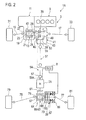
- FIG. 2 shows a drivetrain 1A of the modified embodiment.
- an electric motor 7A is integrated in an intermediate train section, a drive pinion shaft 59A thereof for example, so as to directly drive it.
- a coaxial reduction gear set such as planetary gears may be interposed between the electric motor 7A and the drive pinion shaft 59A.
- the electric motor 7A may be integrated in a propeller shaft 37 or any other rotary elements, instead of the drive pinion shaft 59A.
- This modified embodiment exhibits effects similar to those of the first embodiment as described above.
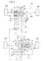
- FIG. 3 shows a drivetrain 1B according to such an embodiment.
- the first axles are the rear axles 15B, 17B and the second axles are the front axles 75B,77B.
- the drivetrain 1B is comprised of a first drivetrain section 3B, a second drivetrain section 5B, and an intermediate train section including a propeller shaft 37 interposed therebetween.
- the first drivetrain section 3B steadily transmits drive force by a transmission 11 including a motor 9 via a rear differential 13B to the rear axles 15B, 17B, thereby driving them.
- the second drivetrain section 5B is drivingly coupled with the front axles 75B, 77B via a front differential 63B.
- the intermediate train section when connected with both the drivetrain sections 3B, 5B, transmits a part of the drive force transmitted to the first drivetrain section 3B to the second drivetrain section 5B.
- the electric motor 7 is drivingly coupled with the intermediate train section, a drive pinion shaft 59B thereof for example, via a gear set 93.
- the front axles 75B,77B are respectively coupled with front wheels 81B, 83B, and the rear axles 15B,17B are respectively coupled with rear wheels 33B, 35B, thereby running the vehicle.
- running modes can be changed with keeping a state where rotations are synchronized, and the 7 drive modes can be realized as with that case described above.
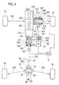
- FIG. 4 shows a drivetrain of such an embodiment.
- a transmission 11C including a motor is disposed at the front. Driving force by the transmission 11C is led out through the output shaft 99.
- An end of the output shaft 99 is drivingly coupled with a propeller shaft 37C via a universal joint 55.
- An opposite end of the propeller shaft 37C is drivingly coupled with a drive pinion shaft 59C via the universal joint 57.
- the drive pinion shaft 59C is comprised of a drive pinion gear 61 and drivingly coupled with a rear differential 63. The drive force by the transmission 11C is thereby steadily transmitted to rear axles 75C,77C via a first drivetrain section 3C including the rear differential 63.
- a second drivetrain section 5C in the drivetrain according to the present embodiment is comprised of a front differential 13C and its side gears 23C,25C are respectively coupled with mediate shafts 27C,29C and further with front axles 15C, 17C, thereby allowing differential motion between the front axles 15C,17C.
- the drivetrain according to the present embodiment is, in order to transmit a part of the drive force of the first drivetrain section 3C to the second drivetrain section 5C, comprised of an intermediate train section interposed therebetween.
- the intermediate train section is, for example, constituted of a propeller shaft 113, a drive pinion shaft 115 connected thereto via a universal joint and such, and a drive pinion gear 117 provided at its end. As the drive pinion gear 117 engages with a ring gear 119 described later, the drive force is transmitted to the second drivetrain section 5C.
- the drivetrain according to the present embodiment is further comprised of a first clutch mechanism 35C and a second clutch mechanism 39C
- the first clutch mechanism 35C disconnectably connects the first drivetrain section 3C with the intermediate train section.
- the second clutch mechanism 39C disconnectably connects the intermediate train section with the second drivetrain section 5C. More specifically, when both the first clutch mechanism 35C and the second clutch mechanism 39C get disengaged, the drive force is transmitted only to the rear wheels. Therefore this vehicle runs in a rear-wheel-drive mode and, when both get engaged, runs in a four-wheel-drive mode.
- a frictional clutch such as a multiplate clutch 103, which is for example housed in a transfer 41C combined with the transmission 11C.
- a frictional clutch such as a multiplate clutch 103
- one set of disks of the multiplate clutch 103 is supported by a clutch case 101 and another set of disks is supported by an output shaft 99. It may be supported by any other rotary element of the first drivetrain section 3C, instead of the output shaft 99.
- the first clutch mechanism 35C is comprised of an actuator 105 driven by a solenoid or such and can thereby switch between its engagement and disengagement.
- the clutch case 101 is for example comprised of a sprocket 107 and is, by means of a chain 112, capable of outputting a part of the drive force to the intermediate train section.
- a gear set or any other coupling form may be used.
- the second clutch mechanism 39C along with, or maybe as a separate body from, the front differential 13C is housed in an outer case 121.
- the outer case 121 is comprised of a ring gear 119, which engages with the drive pinion gear 117 to receive the drive force from the intermediate train section.
- the outer case 121 disconnectably connects with the casing 47C of the front differential 13C by means of a claw clutch 123. Instead of the claw clutch, a clutch of another type such as a frictional clutch may be applied thereto.
- the second clutch mechanism 39C is comprised of an actuator 125 driven by a solenoid or such and can thereby switch between its engagement and disengagement.
- both the first clutch mechanism 35 and the second clutch mechanism 39 get disengaged, the drive force is transmitted only to the rear wheels and then the vehicle runs in a rear-wheel-drive mode.
- both get engaged as the drive force is transmitted to the front wheels as well, the vehicle runs in a four-wheel-drive mode.
- the electric motor 7C is comprised of an output shaft 109 which rotates by its drive force, and the output shaft 109 is coupled with the propeller shaft 113 via a universal joint and such. Alternatively it may be connected via a gear mechanism or such to the intermediate train section. Further the output shaft 109 is comprised of a sprocket 111 engaging with a chain 112. Alternatively, as described above, instead of the chain drive, a gear set or any other coupling form may be used.
- the electric motor 7C in addition to the motor, can also give drive force to the vehicle.
- an ECU 8 may be provided, which is connected to the clutch mechanisms 35C,39C, the electric motor 7 and the other elements.
- running modes can be changed with keeping a state where rotations are synchronized, and these seven drive modes can be realized.
- the device can suppress loss of driving energy and does not cause generation of great frictional heat that leads to exhaustion of the frictional clutch.
- a hybrid system can be realized by such a simple construction. It is enabled that various drive modes enable the vehicle to run in various ways suitable to various road surface conditions.
- the devices are applied to four-wheeled vehicles have been described heretofore, but the devices may be of course applied to a vehicle having more than four wheels. Further to any of the constructions described above applicable is a synchronizer as well. Further, to the electric motor applicable is a motor/generator which has a function of regenerating energy when decelerating.
- a drivetrain having improved energy efficiency in use of an electric motor is provided.
Abstract
Description
- The present invention relates to a drivetrain for a vehicle, which is changeable from a two-wheel-drive mode into a four-wheel-drive mode, and in particular relates to a drivetrain that can uncouple a part of a rotary section from the drivetrain in the two-wheel-drive mode.
- A so-called part-time four-wheel-drive vehicle is comprised of primary axles (front axles for example) steadily driven by a primary drivetrain and secondary axles (rear axles for example) driven by a secondary drivetrain. When a changeover device uncouples the secondary drivetrain from the primary drivetrain, the vehicle runs in a two-wheel-drive mode. When the changeover device couples the secondary drivetrain with the primary drivetrain, drive force is transmitted via a shaft to the secondary drivetrain, thereby realizing a four-wheel-drive mode.
- Although the aforementioned changeover is, without a speed synchronizer, enabled only in a case where the vehicle is idling, there are also known drivetrains which enables changeover during travel. In the latter drivetrains, frictionally-locking clutches are often applied. The following
Patent Literature 1 discloses a related art. - [PTL 1]: Japanese Patent Application Laid-open No.
2009-269605 - According to the art disclosed in the
PTL 1, in a case where the secondary drivetrain is uncoupled (two-wheel-drive mode), a section of the secondary drivetrain located between the changeover device and the frictionally-locking clutch is uncoupled from both the drive force and-driven wheels of the secondary axles. Then the drive force does not bear acceleration and deceleration of the section of the secondary drivetrain in question and therefore this configuration contributes improvement of fuel efficiency. On the other hand in the course of changing the two-wheel-drive mode into a four-wheel-drive mode, the section of the secondary drivetrain at rest must be accelerated by frictional force of the frictionally-locking clutch, thereby establishing synchronism of the rotation speed relative to the secondary axles. Because the driving energy must be partly wasted as frictional heat, vehicle's response to the output will be diminished, there still must be a room for improvement of fuel efficiency, and further this relatively great frictional heat will cause rapid exhaustion of the clutch. The present invention has been achieved in view of these problems. - According to an aspect of the present invention, a drivetrain transmits a first drive force from a transmission including a motor to a first axle and a second axle. This drivetrain is comprised of: a first drivetrain section drivingly coupled with the first axle to steadily transmit the first drive force to the first axle; a second drivetrain section drivingly coupled with the second axle; an intermediate train section interposed between the first drivetrain section and the second drive section, the intermediate train section being capable of transmitting a part of the first drive force to the second drive section; an electric motor drivingly coupled with the intermediate train section to give a second drive force to the intermediate train section; a first clutch disconnectably connecting the first drivetrain section with the intermediate train section; and a second clutch disconnectably connecting the intermediate train section with the second drivetrain section.
-
-
FIG. 1 is a schematic drawing depicting a drivetrain according to a first embodiment of the present invention. -
FIG. 2 is a schematic drawing depicting a drivetrain according to a second embodiment of the present invention. -
FIG. 3 is a schematic drawing depicting a drivetrain according to a third embodiment of the present invention. -
FIG. 4 is a schematic drawing depicting a drivetrain according to a fourth embodiment of the present invention. - Exemplary embodiments of the present invention will be described hereinafter with reference to
FIGs. 1 through 4 . - Throughout the specification and the appended claims, the term "motor" should be taken in the broad sense of a drive force source including an internal combustion engine and an electric motor unless otherwise noted.
- A first embodiment of the present invention will be described below. As the following description takes a front-wheel-drive based vehicle in which a motor is steadily connected with its front axle as an example, first axles are front axles and second axles are rear axles, but this relation may be reversed. The present embodiment may be further applied to a rear-wheel-drive based vehicle or the other types of vehicles.
- Referring to
FIG. 1 , a vehicle comprising a motor 9 transmits drive force to adrivetrain 1 via atransmission 11. Thedrivetrain 1 is comprised of afirst drivetrain section 3, asecond drivetrain section 5, and an intermediate train section including apropeller shaft 37 interposed therebetween. Thefirst drivetrain section 3 steadily transmits the transmitted drive force via afront differential 13 tofront axles second drivetrain section 5 is drivingly coupled withrear axles rear differential 63. The intermediate train section, when connected with both thedrivetrain sections first drivetrain section 3 to thesecond drivetrain section 5. - The
drivetrain 1 is further comprised of afirst clutch mechanism 35 and asecond clutch mechanism 39. Thefirst clutch mechanism 35 disconnectably connects thefirst drivetrain section 3 with the intermediate train section. Thesecond clutch mechanism 39 disconnectably connects the intermediate train section with thesecond drivetrain section 5. More specifically, when both thefirst clutch mechanism 35 and thesecond clutch mechanism 39 get disconnected, the drive force is transmitted only to the front wheels and therefore the vehicle runs in a front-wheel drive mode. By contrast, when both these mechanisms get connected, the drive force is transmitted also to the rear wheels and therefore the vehicle runs in a four-wheel drive mode. - Further the
drivetrain 1 is comprised of anelectric motor 7, which is drivingly coupled with the intermediate train section. Theelectric motor 7 drives the intermediate train section including thepropeller shaft 37, thereby rotation speeds are synchronized without friction in the clutches at a time of shift into the four-wheel drive mode. - In more detail, to the motor 9 applicable preferably is an internal combustion engine such as a gasoline engine. In combination with, or instead of, the internal combustion engine, an electric motor or any other driving force source may be used. The motor 9 is connected with the
front differential 13 via thetransmission 11. Thetransmission 11 can by itself selectively enable and disable transmission of the driving force, as with one of the prior art. - The
drivetrain section 3 is comprised of afront differential 13. The totality of thefront differential 13 may be housed and supported by abell housing 19 coupled with thetransmission 11. Thefront differential 13, via aring gear 21, receives the drive force from thetransmission 11 and thereby itscasing 47 rotates about its axis. - The
casing 47 contains a differential gear set of a bevel gear type or another type. Toside gears mediate shafts front axles front differential 13 differentially distributes the received drive force to thefront axles front axles front wheels front wheels - The
drivetrain 1 is, to transmit a part of the aforementioned drive force to the intermediate train section, comprised of atransfer 41. Thetransfer 41 is comprised of atransfer case 43, which is coupled with thebell housing 19 for instance to have these interiors in communication with each other. - The
transfer 41 is comprised of afirst clutch mechanism 35 housed in thetransfer case 43. Thefirst clutch mechanism 35 is, on one hand, comprised of ahollow shaft 45 connected with thecasing 47 of thefront differential 13, thereby receiving a part of the drive force applied to thecasing 47. Thefirst clutch mechanism 35 is, on the other hand, comprised of an intermediate shaft comprising aring gear 49. Thering gear 49 meshes with apinion gear 53, which is coupled with anoutput shaft 51. As both thering gear 49 and thepinion gear 53 are bevel gears, theoutput shaft 51 forms a proper angle, 90 degrees for example, relative to thefront axles transfer case 43. - To the
first clutch mechanism 35 applied is a claw clutch such as a dog clutch, but any other type of clutches such as a friction clutch may be instead applied thereto. Thefirst clutch mechanism 35 is comprised of an actuator based on a solenoid, an electric motor, or a hydraulic device, to enable changeover between connection and disconnection. When thefirst clutch mechanism 35 gets connected, the drive force received from thefront differential 13 is output to theoutput shaft 51. When thefirst clutch mechanism 35 gets disconnected, theoutput shaft 51 is uncoupled from thefirst drivetrain section 3. - The
output shaft 51 is a part of the intermediate train section and its end is, via auniversal joint 55, drivingly coupled with thepropeller shaft 37. An opposite end of thepropeller shaft 37 is drivingly coupled with adrive pinion shaft 59 via auniversal joint 55. Thedrive pinion shaft 59 is also a part of the intermediate train section. - The
drive pinion shaft 59 is, to establish driving coupling with the rear differential 63, comprised of adrive pinion gear 61. The shaft is further comprised of agear 97 for receiving drive force from theelectric motor 7. Alternatively thegear 97 may be provided in any part in the intermediate train section. - The
second drivetrain section 5 is comprised of a rear differential 63, a secondclutch mechanism 39, andrear axles clutch mechanism 39 are housed in a single carrier case. Alternatively they may be housed in separate carrier cases but are preferably supported so as not to misalign these axes. - The rear differential 63 is comprised of a
casing 64 and is rotatably supported by the carrier case. Thecasing 64 is comprised of aring gear 65 meshing with thedrive pinion gear 61 and thereby receives drive force from the motor 9 via thedrive pinion shaft 59 to rotate about its axis. Thecasing 64 contains a differential gear set of a bevel gear type or another type, and to its side gears 67,69 respectively connected are left and right mediateshafts - To one of the mediate
shafts 71,73 (the right mediateshaft 73 in this example) connected is the secondclutch mechanism 39. A friction clutch such as a multiplate clutch 87 is applied to the secondclutch mechanism 39 but any other clutch such as a claw clutch may be applied thereto. Use of the multiplate clutch is beneficial in controlling distribution of the drive force to the front and rear axles by increasing or decreasing pressure on the clutch plates. - When a description will be given with taking a structure an example, in which the multiplate clutch 87 is used as the second
clutch mechanism 39, the secondclutch mechanism 39 is comprised of aclutch case 83 supporting one set of disks, ahub shaft 85 supporting another set of disks, the multiplate clutch 87 constituted of the paired set of disks, and anactuator 89 comprised of a solenoid. Instead of the solenoid, any proper pressure device such as an electric motor or a hydraulic device that is electrically controllable may be applied thereto. Based on this construction, the secondclutch mechanism 39 can change over connection and disconnection between theclutch case 83 and thehub shaft 85. - To the
clutch case 83 drivingly connected is one of the mediateshafts 71,73 (the right mediateshaft 73 in this example), thereby theclutch case 83 can receives drive force from the intermediate train section. - To the
hub shaft 85 connected is one of therear axles 75,77 (the rightrear axle 77 in this example), and to another of the mediateshafts 71,73 (the left mediateshaft 71 in this example) connected is another of therear axles 75,77 (the leftrear axle 75 in this example). Thereby, when the secondclutch mechanism 39 gets connected, the rear differential 63 differentially distributes the received drive force from the intermediate train section to therear axles rear axles rear wheels rear wheels 78,81, in addition to thefront wheels - When the second
clutch mechanism 39 gets disconnected, as oneside gear 69 idles, no drive force is transmitted to theother side gear 67, thereby the rear differential 63 does not transmit drive force to therear wheels rear wheels clutch mechanism 35 then gets disconnected, the intermediate train section gets uncoupled from thedrivetrain 1 and then comes to idle. - More specifically, the second
clutch mechanism 39 disconnectably connects the intermediate train section with thesecond drivetrain section 5. In the meantime, instead of the structure as described above, an alternative structure may be used, in which the intermediate train section is connected with the clutch mechanism and the rear differential is, via the clutch mechanism, connected with the intermediate train section. - The
electric motor 7 is comprised of agear 95 meshing with thegear 97. Theelectric motor 7 is, via a gear set 93 constituted of thegears drive pinion shaft 59 or connected with any other part of the intermediate train section. The gear set 93 may be a reduction gear set in order to adapt relatively high-speed rotation by theelectric motor 7 to rotation suitable for thedrive pinion shaft 59. Further instead of the gear set, any other form of link such as link by a chain and a sprocket may be used. - As described above, connection and disconnection of the first
clutch mechanism 35 and the secondclutch mechanism 39 are electrically controlled and operation of theelectric motor 7 is electrically controlled as well. To control them comprehensively, an electronic control unit (ECU) 8 may be provided and the firstclutch mechanism 35, the secondclutch mechanism 39 and theelectric motor 7 may be connected thereto. TheECU 8 may be under direct manual control by a driver person or alternatively may be automatically controlled by any other electronic control means. TheECU 8 further detects rotation speeds of theelectric motor 7, thedrive pinion shaft 59 and the other rotary elements. - When the first
clutch mechanism 35 and the secondclutch mechanism 39 get disengaged synchronously, the drive force is transmitted from the motor 9 via thetransmission 11 only to the front differential 13, and is via the front differential 13 distributed via the mediateshafts axles front wheels - When the first
clutch mechanism 35 and the secondclutch mechanism 39 get engaged synchronously, a part of the drive force is transmitted via thetransfer 41 also to thesecond drivetrain section 5. This drive force is transmitted via thepropeller shaft 37 to the rear differential 63, and is via the rear differential 63 distributed via the mediateshafts axles rear wheels - In the two-wheel-drive mode, as the first
clutch mechanism 35 and the secondclutch mechanism 39 get disengaged, the intermediate train section is uncoupled from thedrivetrain 1 and thus does not put a load on the motor 9, thereby improving fuel efficiency. - When in the two-wheel-drive mode, the drive force by the motor 9 does not act on the intermediate train section and therefore rotation of the intermediate train section is not synchronized with that of the other parts of the
drivetrain 1. Thus when it is changed over into the four-wheel-drive mode, synchronization of rotation speeds is required. TheECU 8 detects the rotation speed of thedrive pinion shaft 59 in particular and controls the rotation speed of theelectric motor 7 so as to synchronize it with the rotation speeds of thefirst drivetrain section 3 and thesecond drivetrain section 5. As these rotation speeds are first synchronized and thereafter the firstclutch mechanism 35 and the secondclutch mechanism 39 are driven, the firstclutch mechanism 35 and the secondclutch mechanism 39 can respectively get engaged without slip, or with very limited slip, among these clutch plates. - Drive of the first
clutch mechanism 35 and the secondclutch mechanism 39 and start of theelectric motor 7 can be synchronously executed under certain conditions. They may not be concurrent, however. Theelectric motor 7 may be first started and, after the elapse of a certain time, theclutch mechanisms drive pinion shaft 59 and the rotation speed of thefirst drivetrain section 3 and thesecond drivetrain section 5 comes below a certain value, theclutch mechanisms clutch mechanism 35 and the engagement of the secondclutch mechanism 39. Alternatively, these controls may be made under any other proper conditions. - According to the present embodiment, combinations of switch of the
transmission 11 and theclutch mechanisms electric motor 7 can realize running modes exemplified in Table 1.Table 1 A LIST OF RUNNING MODES normal FF mode disconnect mode normal 4WD mode hybrid FF mode hybrid 4WD mode pure EV-FF mode pure EV-FR mode T/M ON ON ON ON ON OFF OFF first clutch device CLOSE OPEN CLOSE CLOSE CLOSE CLOSE OPEN second clutch device OPEN OPEN CLOSE OPEN CLOSE OPEN CLOSE electric motor OFF OFF OFF ON ON ON ON propeller shaft driven idle driven driven driven driven driven - When the transmission 11 (referred to as "T/M" in Table 1) is made connected ("ON" in Table 1), the first
clutch mechanism 35 is made engaged ("CLOSE" in Table 1), the secondclutch mechanism 39 is made disengaged ("OPEN" in Table 1), and theelectric motor 7 is switched OFF, the vehicle of the present embodiment runs in a normal front-wheel drive mode ("normal FF mode" in Table 1) . Then thepropeller shaft 37 receives the drive force and therefore rotates. - If the
transmission 11, the secondclutch mechanism 39 and theelectric motor 7 are kept in the aforementioned state and the firstclutch mechanism 35 gets disengaged, the vehicle runs still in the front-wheel drive mode. Then the vehicle is in a disconnect mode in which the drive force is not transmitted to thepropeller shaft 37 and therefore thepropeller shaft 37 can stall. - If the
transmission 11 and theelectric motor 7 are kept in the aforementioned state and theclutch mechanisms propeller shaft 37 rotates. A so-called on-demand-coupling function can be given to the vehicle, in which, by controlling pressure on the multiplate clutch 87, distribution of the drive force to the rear wheels is controlled. - It is possible to additionally use drive force of the
electric motor 7 to run the vehicle (a hybrid mode). For example, when theelectric motor 7 is switched ON in the normal FF mode, the vehicle runs in a hybrid FF mode in which both the motor 9 and theelectric motor 7 exert drive force on the front wheels. When the secondclutch mechanism 39 is made engaged in this state, the vehicle runs in a hybrid 4WD mode in which both the motor 9 and theelectric motor 7 exert drive force and the drive force is transmitted to both the front and rear wheels. - Alternatively, it is possible not to use the motor 9 but to use the
electric motor 7 only, to run the vehicle (a pure EV mode). When thetransmission 11 is disconnected ("OFF" in Table 1) in the normal FF mode and theelectric motor 7 is switched ON, the vehicle runs in a pure EV-FF mode in which theelectric motor 7 drives the front wheels. Alternatively, when the firstclutch mechanism 35 gets disengaged and the secondclutch mechanism 39 gets engaged, the vehicle runs in a pure EV-FR mode in which theelectric motor 7 drives the rear wheels. - More specifically, the present embodiment enables at least the aforementioned seven running modes. These seven modes may be put on manual selection by a driver person or another construction may be used, in which a controller may automatically determine and select one of the running modes on the basis of running states of the vehicle detected by various sensors.
- The intermediate train section can be, in the two-wheel drive mode, put in a stalled state according to the present embodiment. As driving energy is not exhausted to accelerate or decelerate the intermediate train section, energy efficiency can be improved.
- Further according to the present embodiment, at a time of changeover from the two-wheel drive mode to the four-wheel drive mode, the rotation speed of the intermediate train section can be in advance synchronized with that of the first drivetrain section and the second drivetrain section by the electric motor. As it is not necessary to cause considerable friction in the frictional clutch for the purpose of synchronization, loss of drive energy can be suppressed, and wear of the frictional clutch caused by considerable frictional heat will not occur. Excellent energy efficiency, good response to output from the motor, and a long life of the clutch can be expected.
- Further according to the present embodiment, a hybrid system can be realized not by a complex structure in which an internal combustion engine and an electric motor are combined together in a transmission, but by the simple structure as described above. Further as exemplified in Table 1, various running modes can be realized even by the simple structure. A conventional hybrid system having a system in which an internal combustion engine and an electric motor are combined together cannot readily realize either a pure EV-FR mode or a pure EV-FF mode depending on whether this system is placed on the side of the front wheels or the side of the rear wheels. The present embodiment can realized both these modes and therefore enable various ways of run adapted for various road surface conditions.
- By modifying the aforementioned embodiment, it is possible that the electric motor is combined directly with the intermediate train section without having intervening gears.
FIG. 2 shows adrivetrain 1A of the modified embodiment. - Referring to
FIG. 2 , anelectric motor 7A is integrated in an intermediate train section, adrive pinion shaft 59A thereof for example, so as to directly drive it. To adapt relating high-speed rotation by theelectric motor 7A to rotation suitable for thedrive pinion shaft 59A, a coaxial reduction gear set such as planetary gears may be interposed between theelectric motor 7A and thedrive pinion shaft 59A. Further, theelectric motor 7A may be integrated in apropeller shaft 37 or any other rotary elements, instead of thedrive pinion shaft 59A. - This modified embodiment exhibits effects similar to those of the first embodiment as described above.
- Further as stated already, any of the aforementioned embodiments can be applied to vehicles of rear-wheel-based four-wheel-drive systems.
FIG. 3 shows adrivetrain 1B according to such an embodiment. - Contrary to the embodiments described so far, the first axles are the
rear axles front axles FIG. 3 , thedrivetrain 1B is comprised of afirst drivetrain section 3B, asecond drivetrain section 5B, and an intermediate train section including apropeller shaft 37 interposed therebetween. Thefirst drivetrain section 3B steadily transmits drive force by atransmission 11 including a motor 9 via a rear differential 13B to therear axles second drivetrain section 5B is drivingly coupled with thefront axles drivetrain sections first drivetrain section 3B to thesecond drivetrain section 5B. - The
electric motor 7 is drivingly coupled with the intermediate train section, adrive pinion shaft 59B thereof for example, via a gear set 93. Thefront axles front wheels 81B, 83B, and therear axles rear wheels 33B, 35B, thereby running the vehicle. - By changing over the first
clutch mechanism 35 and the secondclutch mechanism 39 respectively, running modes can be changed with keeping a state where rotations are synchronized, and the 7 drive modes can be realized as with that case described above. - Further, even in a rear-wheel-drive base vehicle, an embodiment in which a motor is disposed at its front, which is a so-called FR-layout, could be possible.
FIG. 4 shows a drivetrain of such an embodiment. - Referring to
FIG. 4 , atransmission 11C including a motor is disposed at the front. Driving force by thetransmission 11C is led out through theoutput shaft 99. - An end of the
output shaft 99 is drivingly coupled with apropeller shaft 37C via auniversal joint 55. An opposite end of thepropeller shaft 37C is drivingly coupled with adrive pinion shaft 59C via theuniversal joint 57. Thedrive pinion shaft 59C is comprised of adrive pinion gear 61 and drivingly coupled with arear differential 63. The drive force by thetransmission 11C is thereby steadily transmitted torear axles first drivetrain section 3C including therear differential 63. - A
second drivetrain section 5C in the drivetrain according to the present embodiment is comprised of a front differential 13C and its side gears 23C,25C are respectively coupled with mediateshafts 27C,29C and further withfront axles 15C, 17C, thereby allowing differential motion between thefront axles 15C,17C. - The drivetrain according to the present embodiment is, in order to transmit a part of the drive force of the
first drivetrain section 3C to thesecond drivetrain section 5C, comprised of an intermediate train section interposed therebetween. The intermediate train section is, for example, constituted of apropeller shaft 113, adrive pinion shaft 115 connected thereto via a universal joint and such, and adrive pinion gear 117 provided at its end. As thedrive pinion gear 117 engages with aring gear 119 described later, the drive force is transmitted to thesecond drivetrain section 5C. - The drivetrain according to the present embodiment is further comprised of a first
clutch mechanism 35C and a secondclutch mechanism 39C The firstclutch mechanism 35C disconnectably connects thefirst drivetrain section 3C with the intermediate train section. Further the secondclutch mechanism 39C disconnectably connects the intermediate train section with thesecond drivetrain section 5C. More specifically, when both the firstclutch mechanism 35C and the secondclutch mechanism 39C get disengaged, the drive force is transmitted only to the rear wheels. Therefore this vehicle runs in a rear-wheel-drive mode and, when both get engaged, runs in a four-wheel-drive mode. - To the first
clutch mechanism 35C applied is a frictional clutch such as a multiplate clutch 103, which is for example housed in atransfer 41C combined with thetransmission 11C. According to the example to which themultiplate clutch 103 is applied, one set of disks of themultiplate clutch 103 is supported by aclutch case 101 and another set of disks is supported by anoutput shaft 99. It may be supported by any other rotary element of thefirst drivetrain section 3C, instead of theoutput shaft 99. The firstclutch mechanism 35C is comprised of anactuator 105 driven by a solenoid or such and can thereby switch between its engagement and disengagement. - The
clutch case 101 is for example comprised of asprocket 107 and is, by means of achain 112, capable of outputting a part of the drive force to the intermediate train section. Instead of the chain drive, a gear set or any other coupling form may be used. - The second
clutch mechanism 39C along with, or maybe as a separate body from, the front differential 13C is housed in anouter case 121. Theouter case 121 is comprised of aring gear 119, which engages with thedrive pinion gear 117 to receive the drive force from the intermediate train section. Theouter case 121 disconnectably connects with thecasing 47C of the front differential 13C by means of aclaw clutch 123. Instead of the claw clutch, a clutch of another type such as a frictional clutch may be applied thereto. The secondclutch mechanism 39C is comprised of an actuator 125 driven by a solenoid or such and can thereby switch between its engagement and disengagement. - When both the first
clutch mechanism 35 and the secondclutch mechanism 39 get disengaged, the drive force is transmitted only to the rear wheels and then the vehicle runs in a rear-wheel-drive mode. When both get engaged, as the drive force is transmitted to the front wheels as well, the vehicle runs in a four-wheel-drive mode. - The
electric motor 7C is comprised of anoutput shaft 109 which rotates by its drive force, and theoutput shaft 109 is coupled with thepropeller shaft 113 via a universal joint and such. Alternatively it may be connected via a gear mechanism or such to the intermediate train section. Further theoutput shaft 109 is comprised of asprocket 111 engaging with achain 112. Alternatively, as described above, instead of the chain drive, a gear set or any other coupling form may be used. Theelectric motor 7C, in addition to the motor, can also give drive force to the vehicle. - As with the embodiments so far, an
ECU 8 may be provided, which is connected to theclutch mechanisms electric motor 7 and the other elements. - As with the embodiments so far, by switching the first
clutch mechanism 35C and the secondclutch mechanism 39C respectively, running modes can be changed with keeping a state where rotations are synchronized, and these seven drive modes can be realized. The device can suppress loss of driving energy and does not cause generation of great frictional heat that leads to exhaustion of the frictional clutch. A hybrid system can be realized by such a simple construction. It is enabled that various drive modes enable the vehicle to run in various ways suitable to various road surface conditions. - Examples in which the devices are applied to four-wheeled vehicles have been described heretofore, but the devices may be of course applied to a vehicle having more than four wheels. Further to any of the constructions described above applicable is a synchronizer as well. Further, to the electric motor applicable is a motor/generator which has a function of regenerating energy when decelerating.
- Although the invention has been described above by reference to certain exemplary embodiments of the invention, the invention is not limited to the exemplary embodiments described above. Modifications and variations of the embodiments described above will occur to those skilled in the art, in light of the above teachings.
- A drivetrain having improved energy efficiency in use of an electric motor is provided.
Claims (4)
- A drivetrain capable of transmitting a first drive force from a transmission including a motor to a first axle and a second axle, comprising:a first drivetrain section drivingly coupled with the first axle to steadily transmit the first drive force to the first axle;a second drivetrain section drivingly coupled with the second axle;an intermediate train section interposed between the first drivetrain section and the second drive section, the intermediate train section being capable of transmitting a part of the first drive force to the second drive section;an electric motor drivingly coupled with the intermediate train section to give a second drive force to the intermediate train section;a first clutch disconnectably connecting the first drivetrain section with the intermediate train section; anda second clutch disconnectably connecting the intermediate train section with the second drivetrain section.
- The drivetrain of claim 1, wherein the electric motor connects with the second drivetrain via a gear set.
- The drivetrain of claim 1, wherein one selected from the group consisting of the first clutch and the second clutch is a claw clutch and the other is a friction clutch.
- The drivetrain of any of claims 1-3, further comprising:a control device for enabling synchronous connection of the second clutch, the control device being configured to control a rotation speed of the electric motor in advance of the connection.
Applications Claiming Priority (2)
| Application Number | Priority Date | Filing Date | Title |
|---|---|---|---|
| JP2012111188A JP5926113B2 (en) | 2012-05-15 | 2012-05-15 | Automotive driveline device |
| PCT/JP2013/063132 WO2013172258A1 (en) | 2012-05-15 | 2013-05-10 | Automobile powertrain |
Publications (3)
| Publication Number | Publication Date |
|---|---|
| EP2851232A1 true EP2851232A1 (en) | 2015-03-25 |
| EP2851232A4 EP2851232A4 (en) | 2016-04-06 |
| EP2851232B1 EP2851232B1 (en) | 2021-08-04 |
Family
ID=49583664
Family Applications (1)
| Application Number | Title | Priority Date | Filing Date |
|---|---|---|---|
| EP13790640.0A Active EP2851232B1 (en) | 2012-05-15 | 2013-05-10 | Automobile powertrain |
Country Status (5)
| Country | Link |
|---|---|
| US (2) | US9352647B2 (en) |
| EP (1) | EP2851232B1 (en) |
| JP (1) | JP5926113B2 (en) |
| CN (2) | CN104284795B (en) |
| WO (1) | WO2013172258A1 (en) |
Cited By (4)
| Publication number | Priority date | Publication date | Assignee | Title |
|---|---|---|---|---|
| US9499049B2 (en) | 2012-09-06 | 2016-11-22 | Iveco S.P.A. | Hybrid vehicle comprising a torque distributor |
| WO2018086925A1 (en) * | 2016-11-08 | 2018-05-17 | Audi Ag | Drive device for a motor vehicle, corresponding motor vehicle, and method for operating a drive device |
| WO2018086926A1 (en) * | 2016-11-08 | 2018-05-17 | Audi Ag | Drive device for a motor vehicle, corresponding motor vehicle, and method for operating a drive device |
| WO2019141459A1 (en) * | 2018-01-22 | 2019-07-25 | Magna powertrain gmbh & co kg | Vehicle comprising a transfer case and method for operating a vehicle comprising a transfer case |
Families Citing this family (25)
| Publication number | Priority date | Publication date | Assignee | Title |
|---|---|---|---|---|
| US8042642B2 (en) * | 2008-08-14 | 2011-10-25 | American Axle & Manufacturing, Inc. | Motor vehicle with disconnectable all-wheel drive system |
| US11161403B2 (en) | 2012-02-03 | 2021-11-02 | Ge Hybrid Technologies, Llc | Apparatus and method for delivering power in a hybrid vehicle |
| EP2809540B1 (en) * | 2012-02-03 | 2019-12-18 | GE Hybrid Technologies, LLC | Apparatus for delivering power in a hybrid vehicle |
| JP5926113B2 (en) * | 2012-05-15 | 2016-05-25 | Gknドライブラインジャパン株式会社 | Automotive driveline device |
| CN106029427B (en) * | 2014-02-27 | 2017-11-28 | 日产自动车株式会社 | The clutch controller of 4 wheel drive vehicles |
| JP6221830B2 (en) * | 2014-02-28 | 2017-11-01 | 日産自動車株式会社 | Clutch control device for four-wheel drive vehicle |
| US9783053B2 (en) * | 2014-02-28 | 2017-10-10 | Nissan Motor Co., Ltd. | Clutch control device for 4-wheel drive vehicle |
| DE102014103471A1 (en) * | 2014-03-14 | 2015-09-17 | Dr. Ing. H.C. F. Porsche Aktiengesellschaft | Electric actuator |
| FR3020324B1 (en) * | 2014-04-25 | 2016-04-22 | Poclain Hydraulics Ind | DRIVE ASSEMBLY FOR A MOTOR SHAFT OF A MOTOR VEHICLE |
| SE1450830A1 (en) * | 2014-07-02 | 2016-01-03 | Borgwarner Torqtransfer Systems Ab | A vehicle driveline system |
| JP2016034812A (en) * | 2014-08-04 | 2016-03-17 | 日産自動車株式会社 | Dog clutch of four-wheel-drive vehicle |
| JP6176221B2 (en) * | 2014-10-17 | 2017-08-09 | マツダ株式会社 | Vehicle drive device |
| JP6540086B2 (en) * | 2015-02-20 | 2019-07-10 | 三菱自動車工業株式会社 | Control device for four-wheel drive vehicle |
| JP6187529B2 (en) | 2015-04-16 | 2017-08-30 | トヨタ自動車株式会社 | 4 wheel drive vehicle |
| WO2016191322A1 (en) * | 2015-05-28 | 2016-12-01 | Borgwarner Inc. | Driveline disconnect using multimode clutches |
| US10221903B2 (en) * | 2016-02-04 | 2019-03-05 | Ford Global Technologies, Llc | Vehicle with wheel-end disconnect and associated control method |
| DE102016221880B4 (en) * | 2016-11-08 | 2023-08-10 | Audi Ag | Drive device for a motor vehicle |
| DE102017206516B4 (en) * | 2017-04-18 | 2024-04-25 | Magna powertrain gmbh & co kg | Drivetrain for a hybrid vehicle, in particular for a temporarily four-wheel drive motor vehicle |
| DE102017207834A1 (en) * | 2017-05-09 | 2018-11-15 | Bayerische Motoren Werke Aktiengesellschaft | Drive unit for an electric vehicle and motor vehicle |
| DE102017222547A1 (en) * | 2017-12-13 | 2019-06-13 | Robert Bosch Gmbh | Method for operating a vehicle with at least two drive units |
| US10704663B2 (en) | 2018-09-06 | 2020-07-07 | American Axle & Manufacturing, Inc. | Modular disconnecting drive module with torque vectoring augmentation |
| US10927937B2 (en) | 2018-09-06 | 2021-02-23 | American Axle & Manufacturing, Inc. | Modular disconnecting drive module with torque vectoring augmentation |
| CN109367399A (en) * | 2018-09-18 | 2019-02-22 | 江西江铃集团新能源汽车有限公司 | 4 wheel driven control device and automobile |
| CN110053476B (en) * | 2019-04-30 | 2021-01-15 | 武汉祥振科技有限公司 | Central limited slip differential device, driving system comprising same and application |
| CN110641291B (en) * | 2019-10-08 | 2021-01-01 | 长安大学 | Control method and system for double-motor electric scooter |
Family Cites Families (22)
| Publication number | Priority date | Publication date | Assignee | Title |
|---|---|---|---|---|
| JP2003335143A (en) * | 2002-05-20 | 2003-11-25 | Toyoda Mach Works Ltd | Active four-wheel drive device |
| JP4029874B2 (en) * | 2003-09-29 | 2008-01-09 | 日産自動車株式会社 | Vehicle drive device |
| US7140461B2 (en) * | 2003-11-26 | 2006-11-28 | Oshkosh Truck Corporation | Power splitting vehicle drive system |
| JP3986494B2 (en) * | 2003-12-02 | 2007-10-03 | アイシン・エィ・ダブリュ株式会社 | Hybrid drive device and automobile equipped with hybrid drive device |
| JP2006168392A (en) * | 2004-12-13 | 2006-06-29 | Hitachi Ltd | Vehicle driving force controlling device |
| US7455135B2 (en) * | 2005-08-15 | 2008-11-25 | Ford Global Technologies, Llc | Torque transfer case for a hybrid electric vehicle |
| US7424924B2 (en) * | 2005-08-15 | 2008-09-16 | Ford Global Technologies, Llc | Hybrid electric vehicle powertrain with torque transfer case |
| GB0603452D0 (en) * | 2006-02-22 | 2006-04-05 | Ford Global Tech Llc | Hybrid motor vehicle driveline |
| CN101801701B (en) * | 2007-08-14 | 2015-01-07 | 格特拉格传动机构和齿轮工厂赫尔曼·哈根迈尔有限公司&两合公司 | Drive train for a motor vehicle |
| US8958965B2 (en) * | 2007-09-13 | 2015-02-17 | Ford Global Technologies Llc | System and method for managing a powertrain in a vehicle |
| US8215440B2 (en) | 2008-05-06 | 2012-07-10 | Getrag Driveline Systems, Gmbh | Drive train for a vehicle with connectable secondary axle |
| US8042642B2 (en) * | 2008-08-14 | 2011-10-25 | American Axle & Manufacturing, Inc. | Motor vehicle with disconnectable all-wheel drive system |
| DE102009005378C5 (en) * | 2008-10-13 | 2018-06-21 | Magna powertrain gmbh & co kg | Powertrain for a motor vehicle |
| KR101760499B1 (en) * | 2009-03-05 | 2017-07-21 | 보그워너 스웨덴 아베 | A device for torque vectoring |
| CN101789032B (en) | 2009-07-23 | 2012-07-18 | 芯原微电子(上海)有限公司 | Design method and structure thereof of physical layout of CUP weld pad zone |
| JP5246340B2 (en) * | 2009-10-05 | 2013-07-24 | トヨタ自動車株式会社 | Control device for vehicle drive device |
| JP2011079421A (en) * | 2009-10-07 | 2011-04-21 | Univance Corp | Driving force transmission device for four-wheel drive vehicle |
| JP5728861B2 (en) * | 2010-09-15 | 2015-06-03 | 株式会社ジェイテクト | Four-wheel drive vehicle and its control device |
| US20140051541A1 (en) * | 2011-04-28 | 2014-02-20 | Jaguar Land Rover Limited | Vehicle and method of controlling a vehicle |
| JP5849770B2 (en) * | 2012-02-29 | 2016-02-03 | 株式会社ジェイテクト | Four-wheel drive vehicle and control device for four-wheel drive vehicle |
| JP5926113B2 (en) * | 2012-05-15 | 2016-05-25 | Gknドライブラインジャパン株式会社 | Automotive driveline device |
| JP6070630B2 (en) * | 2014-05-16 | 2017-02-01 | トヨタ自動車株式会社 | Control device for four-wheel drive vehicle |
-
2012
- 2012-05-15 JP JP2012111188A patent/JP5926113B2/en active Active
-
2013
- 2013-05-10 CN CN201380024481.3A patent/CN104284795B/en active Active
- 2013-05-10 WO PCT/JP2013/063132 patent/WO2013172258A1/en unknown
- 2013-05-10 EP EP13790640.0A patent/EP2851232B1/en active Active
- 2013-05-10 CN CN201810272561.5A patent/CN108466545B/en active Active
-
2014
- 2014-09-19 US US14/491,103 patent/US9352647B2/en active Active
-
2015
- 2015-12-09 US US14/963,404 patent/US10052949B2/en active Active
Cited By (5)
| Publication number | Priority date | Publication date | Assignee | Title |
|---|---|---|---|---|
| US9499049B2 (en) | 2012-09-06 | 2016-11-22 | Iveco S.P.A. | Hybrid vehicle comprising a torque distributor |
| EP2705968B1 (en) * | 2012-09-06 | 2017-11-29 | IVECO S.p.A. | Vehicle comprising a two-shaft torque distributor, control method therefor, computer program and computer-readable means |
| WO2018086925A1 (en) * | 2016-11-08 | 2018-05-17 | Audi Ag | Drive device for a motor vehicle, corresponding motor vehicle, and method for operating a drive device |
| WO2018086926A1 (en) * | 2016-11-08 | 2018-05-17 | Audi Ag | Drive device for a motor vehicle, corresponding motor vehicle, and method for operating a drive device |
| WO2019141459A1 (en) * | 2018-01-22 | 2019-07-25 | Magna powertrain gmbh & co kg | Vehicle comprising a transfer case and method for operating a vehicle comprising a transfer case |
Also Published As
| Publication number | Publication date |
|---|---|
| EP2851232A4 (en) | 2016-04-06 |
| CN108466545A (en) | 2018-08-31 |
| US20160090083A1 (en) | 2016-03-31 |
| JP2013237338A (en) | 2013-11-28 |
| JP5926113B2 (en) | 2016-05-25 |
| CN108466545B (en) | 2021-06-18 |
| CN104284795B (en) | 2018-04-27 |
| US10052949B2 (en) | 2018-08-21 |
| WO2013172258A1 (en) | 2013-11-21 |
| EP2851232B1 (en) | 2021-08-04 |
| US20150053046A1 (en) | 2015-02-26 |
| US9352647B2 (en) | 2016-05-31 |
| CN104284795A (en) | 2015-01-14 |
Similar Documents
| Publication | Publication Date | Title |
|---|---|---|
| EP2851232B1 (en) | Automobile powertrain | |
| KR101906652B1 (en) | Disconnectable driveline for all-wheel drive vehicle | |
| US8534409B2 (en) | Drivetrain for a vehicle and method of controlling same | |
| CN103813924B (en) | The method of vehicle and control vehicle | |
| US9079495B2 (en) | Disconnectable driveline with a multi-speed RDM and PTU | |
| CN103747976B (en) | The method of vehicle and control vehicle | |
| CN110366501A (en) | Power transmission | |
| US20170259662A1 (en) | Drive device for a hybrid-driven motor vehicle | |
| JP2008132976A (en) | Drive unit | |
| CN110582422A (en) | Drive train for a hybrid vehicle, in particular for a temporary four-wheel-drive motor vehicle | |
| JP2019513619A (en) | Vehicle driveline system | |
| US10525829B2 (en) | AWD transverse powertrain with rear wheel bias field | |
| JP2014148267A (en) | Four-wheel drive vehicle | |
| US20100192724A1 (en) | Power transmission device with internal actuator | |
| WO2014076805A1 (en) | Four-wheel drive vehicle power transmission device | |
| US10670128B2 (en) | All-wheel drive driveline with front limited slip differential | |
| CN111717016A (en) | Hybrid power system, engine starting method thereof and hybrid power vehicle | |
| JP4011525B2 (en) | Power transmission device for hybrid vehicle | |
| JPS62173324A (en) | Four-wheel drive device | |
| JPH0867158A (en) | Power transmitting device |
Legal Events
| Date | Code | Title | Description |
|---|---|---|---|
| PUAI | Public reference made under article 153(3) epc to a published international application that has entered the european phase |
Free format text: ORIGINAL CODE: 0009012 |
|
| 17P | Request for examination filed |
Effective date: 20140902 |
|
| AK | Designated contracting states |
Kind code of ref document: A1 Designated state(s): AL AT BE BG CH CY CZ DE DK EE ES FI FR GB GR HR HU IE IS IT LI LT LU LV MC MK MT NL NO PL PT RO RS SE SI SK SM TR |
|
| AX | Request for extension of the european patent |
Extension state: BA ME |
|
| DAX | Request for extension of the european patent (deleted) | ||
| RA4 | Supplementary search report drawn up and despatched (corrected) |
Effective date: 20160309 |
|
| RIC1 | Information provided on ipc code assigned before grant |
Ipc: B60K 6/54 20071001ALI20160303BHEP Ipc: B60W 20/00 20160101ALI20160303BHEP Ipc: B60L 11/14 20060101ALI20160303BHEP Ipc: B60K 17/356 20060101AFI20160303BHEP Ipc: B60K 23/08 20060101ALI20160303BHEP Ipc: B60K 6/48 20071001ALI20160303BHEP Ipc: B60K 6/387 20071001ALI20160303BHEP Ipc: B60K 6/26 20071001ALI20160303BHEP Ipc: B60K 6/52 20071001ALI20160303BHEP Ipc: B60W 10/08 20060101ALI20160303BHEP |
|
| STAA | Information on the status of an ep patent application or granted ep patent |
Free format text: STATUS: EXAMINATION IS IN PROGRESS |
|
| 17Q | First examination report despatched |
Effective date: 20190423 |
|
| STAA | Information on the status of an ep patent application or granted ep patent |
Free format text: STATUS: EXAMINATION IS IN PROGRESS |
|
| REG | Reference to a national code |
Ref country code: DE Ref legal event code: R079 Ref document number: 602013078656 Country of ref document: DE Free format text: PREVIOUS MAIN CLASS: B60K0017356000 Ipc: B60K0006520000 |
|
| GRAP | Despatch of communication of intention to grant a patent |
Free format text: ORIGINAL CODE: EPIDOSNIGR1 |
|
| STAA | Information on the status of an ep patent application or granted ep patent |
Free format text: STATUS: GRANT OF PATENT IS INTENDED |
|
| RIC1 | Information provided on ipc code assigned before grant |
Ipc: B60W 20/00 20160101ALI20210209BHEP Ipc: B60K 6/54 20071001ALI20210209BHEP Ipc: B60K 6/52 20071001AFI20210209BHEP Ipc: B60W 10/08 20060101ALI20210209BHEP Ipc: B60K 23/08 20060101ALI20210209BHEP |
|
| INTG | Intention to grant announced |
Effective date: 20210224 |
|
| GRAS | Grant fee paid |
Free format text: ORIGINAL CODE: EPIDOSNIGR3 |
|
| GRAA | (expected) grant |
Free format text: ORIGINAL CODE: 0009210 |
|
| STAA | Information on the status of an ep patent application or granted ep patent |
Free format text: STATUS: THE PATENT HAS BEEN GRANTED |
|
| AK | Designated contracting states |
Kind code of ref document: B1 Designated state(s): AL AT BE BG CH CY CZ DE DK EE ES FI FR GB GR HR HU IE IS IT LI LT LU LV MC MK MT NL NO PL PT RO RS SE SI SK SM TR |
|
| REG | Reference to a national code |
Ref country code: GB Ref legal event code: FG4D |
|
| REG | Reference to a national code |
Ref country code: AT Ref legal event code: REF Ref document number: 1416641 Country of ref document: AT Kind code of ref document: T Effective date: 20210815 |
|
| REG | Reference to a national code |
Ref country code: CH Ref legal event code: EP |
|
| REG | Reference to a national code |
Ref country code: DE Ref legal event code: R096 Ref document number: 602013078656 Country of ref document: DE |
|
| REG | Reference to a national code |
Ref country code: IE Ref legal event code: FG4D |
|
| REG | Reference to a national code |
Ref country code: LT Ref legal event code: MG9D |
|
| REG | Reference to a national code |
Ref country code: NL Ref legal event code: MP Effective date: 20210804 |
|
| REG | Reference to a national code |
Ref country code: AT Ref legal event code: MK05 Ref document number: 1416641 Country of ref document: AT Kind code of ref document: T Effective date: 20210804 |
|
| PG25 | Lapsed in a contracting state [announced via postgrant information from national office to epo] |
Ref country code: SE Free format text: LAPSE BECAUSE OF FAILURE TO SUBMIT A TRANSLATION OF THE DESCRIPTION OR TO PAY THE FEE WITHIN THE PRESCRIBED TIME-LIMIT Effective date: 20210804 Ref country code: HR Free format text: LAPSE BECAUSE OF FAILURE TO SUBMIT A TRANSLATION OF THE DESCRIPTION OR TO PAY THE FEE WITHIN THE PRESCRIBED TIME-LIMIT Effective date: 20210804 Ref country code: LT Free format text: LAPSE BECAUSE OF FAILURE TO SUBMIT A TRANSLATION OF THE DESCRIPTION OR TO PAY THE FEE WITHIN THE PRESCRIBED TIME-LIMIT Effective date: 20210804 Ref country code: BG Free format text: LAPSE BECAUSE OF FAILURE TO SUBMIT A TRANSLATION OF THE DESCRIPTION OR TO PAY THE FEE WITHIN THE PRESCRIBED TIME-LIMIT Effective date: 20211104 Ref country code: AT Free format text: LAPSE BECAUSE OF FAILURE TO SUBMIT A TRANSLATION OF THE DESCRIPTION OR TO PAY THE FEE WITHIN THE PRESCRIBED TIME-LIMIT Effective date: 20210804 Ref country code: ES Free format text: LAPSE BECAUSE OF FAILURE TO SUBMIT A TRANSLATION OF THE DESCRIPTION OR TO PAY THE FEE WITHIN THE PRESCRIBED TIME-LIMIT Effective date: 20210804 Ref country code: FI Free format text: LAPSE BECAUSE OF FAILURE TO SUBMIT A TRANSLATION OF THE DESCRIPTION OR TO PAY THE FEE WITHIN THE PRESCRIBED TIME-LIMIT Effective date: 20210804 Ref country code: NO Free format text: LAPSE BECAUSE OF FAILURE TO SUBMIT A TRANSLATION OF THE DESCRIPTION OR TO PAY THE FEE WITHIN THE PRESCRIBED TIME-LIMIT Effective date: 20211104 Ref country code: RS Free format text: LAPSE BECAUSE OF FAILURE TO SUBMIT A TRANSLATION OF THE DESCRIPTION OR TO PAY THE FEE WITHIN THE PRESCRIBED TIME-LIMIT Effective date: 20210804 Ref country code: PT Free format text: LAPSE BECAUSE OF FAILURE TO SUBMIT A TRANSLATION OF THE DESCRIPTION OR TO PAY THE FEE WITHIN THE PRESCRIBED TIME-LIMIT Effective date: 20211206 |
|
| PG25 | Lapsed in a contracting state [announced via postgrant information from national office to epo] |
Ref country code: PL Free format text: LAPSE BECAUSE OF FAILURE TO SUBMIT A TRANSLATION OF THE DESCRIPTION OR TO PAY THE FEE WITHIN THE PRESCRIBED TIME-LIMIT Effective date: 20210804 Ref country code: LV Free format text: LAPSE BECAUSE OF FAILURE TO SUBMIT A TRANSLATION OF THE DESCRIPTION OR TO PAY THE FEE WITHIN THE PRESCRIBED TIME-LIMIT Effective date: 20210804 Ref country code: GR Free format text: LAPSE BECAUSE OF FAILURE TO SUBMIT A TRANSLATION OF THE DESCRIPTION OR TO PAY THE FEE WITHIN THE PRESCRIBED TIME-LIMIT Effective date: 20211105 |
|
| PG25 | Lapsed in a contracting state [announced via postgrant information from national office to epo] |
Ref country code: NL Free format text: LAPSE BECAUSE OF FAILURE TO SUBMIT A TRANSLATION OF THE DESCRIPTION OR TO PAY THE FEE WITHIN THE PRESCRIBED TIME-LIMIT Effective date: 20210804 |
|
| PG25 | Lapsed in a contracting state [announced via postgrant information from national office to epo] |
Ref country code: DK Free format text: LAPSE BECAUSE OF FAILURE TO SUBMIT A TRANSLATION OF THE DESCRIPTION OR TO PAY THE FEE WITHIN THE PRESCRIBED TIME-LIMIT Effective date: 20210804 |
|
| REG | Reference to a national code |
Ref country code: DE Ref legal event code: R097 Ref document number: 602013078656 Country of ref document: DE |
|
| PG25 | Lapsed in a contracting state [announced via postgrant information from national office to epo] |
Ref country code: SM Free format text: LAPSE BECAUSE OF FAILURE TO SUBMIT A TRANSLATION OF THE DESCRIPTION OR TO PAY THE FEE WITHIN THE PRESCRIBED TIME-LIMIT Effective date: 20210804 Ref country code: SK Free format text: LAPSE BECAUSE OF FAILURE TO SUBMIT A TRANSLATION OF THE DESCRIPTION OR TO PAY THE FEE WITHIN THE PRESCRIBED TIME-LIMIT Effective date: 20210804 Ref country code: RO Free format text: LAPSE BECAUSE OF FAILURE TO SUBMIT A TRANSLATION OF THE DESCRIPTION OR TO PAY THE FEE WITHIN THE PRESCRIBED TIME-LIMIT Effective date: 20210804 Ref country code: EE Free format text: LAPSE BECAUSE OF FAILURE TO SUBMIT A TRANSLATION OF THE DESCRIPTION OR TO PAY THE FEE WITHIN THE PRESCRIBED TIME-LIMIT Effective date: 20210804 Ref country code: CZ Free format text: LAPSE BECAUSE OF FAILURE TO SUBMIT A TRANSLATION OF THE DESCRIPTION OR TO PAY THE FEE WITHIN THE PRESCRIBED TIME-LIMIT Effective date: 20210804 Ref country code: AL Free format text: LAPSE BECAUSE OF FAILURE TO SUBMIT A TRANSLATION OF THE DESCRIPTION OR TO PAY THE FEE WITHIN THE PRESCRIBED TIME-LIMIT Effective date: 20210804 |
|
| PLBE | No opposition filed within time limit |
Free format text: ORIGINAL CODE: 0009261 |
|
| STAA | Information on the status of an ep patent application or granted ep patent |
Free format text: STATUS: NO OPPOSITION FILED WITHIN TIME LIMIT |
|
| 26N | No opposition filed |
Effective date: 20220506 |
|
| PG25 | Lapsed in a contracting state [announced via postgrant information from national office to epo] |
Ref country code: IT Free format text: LAPSE BECAUSE OF FAILURE TO SUBMIT A TRANSLATION OF THE DESCRIPTION OR TO PAY THE FEE WITHIN THE PRESCRIBED TIME-LIMIT Effective date: 20210804 |
|
| PG25 | Lapsed in a contracting state [announced via postgrant information from national office to epo] |
Ref country code: SI Free format text: LAPSE BECAUSE OF FAILURE TO SUBMIT A TRANSLATION OF THE DESCRIPTION OR TO PAY THE FEE WITHIN THE PRESCRIBED TIME-LIMIT Effective date: 20210804 |
|
| REG | Reference to a national code |
Ref country code: CH Ref legal event code: PL |
|
| REG | Reference to a national code |
Ref country code: BE Ref legal event code: MM Effective date: 20220531 |
|
| GBPC | Gb: european patent ceased through non-payment of renewal fee |
Effective date: 20220510 |
|
| PG25 | Lapsed in a contracting state [announced via postgrant information from national office to epo] |
Ref country code: MC Free format text: LAPSE BECAUSE OF FAILURE TO SUBMIT A TRANSLATION OF THE DESCRIPTION OR TO PAY THE FEE WITHIN THE PRESCRIBED TIME-LIMIT Effective date: 20210804 Ref country code: LU Free format text: LAPSE BECAUSE OF NON-PAYMENT OF DUE FEES Effective date: 20220510 Ref country code: LI Free format text: LAPSE BECAUSE OF NON-PAYMENT OF DUE FEES Effective date: 20220531 Ref country code: CH Free format text: LAPSE BECAUSE OF NON-PAYMENT OF DUE FEES Effective date: 20220531 |
|
| PG25 | Lapsed in a contracting state [announced via postgrant information from national office to epo] |
Ref country code: IE Free format text: LAPSE BECAUSE OF NON-PAYMENT OF DUE FEES Effective date: 20220510 Ref country code: FR Free format text: LAPSE BECAUSE OF NON-PAYMENT OF DUE FEES Effective date: 20220531 |
|
| PG25 | Lapsed in a contracting state [announced via postgrant information from national office to epo] |
Ref country code: GB Free format text: LAPSE BECAUSE OF NON-PAYMENT OF DUE FEES Effective date: 20220510 Ref country code: BE Free format text: LAPSE BECAUSE OF NON-PAYMENT OF DUE FEES Effective date: 20220531 |
|
| PGFP | Annual fee paid to national office [announced via postgrant information from national office to epo] |
Ref country code: DE Payment date: 20230519 Year of fee payment: 11 |
|
| PG25 | Lapsed in a contracting state [announced via postgrant information from national office to epo] |
Ref country code: HU Free format text: LAPSE BECAUSE OF FAILURE TO SUBMIT A TRANSLATION OF THE DESCRIPTION OR TO PAY THE FEE WITHIN THE PRESCRIBED TIME-LIMIT; INVALID AB INITIO Effective date: 20130510 |