EP2851184A1 - Process and apparatus for shaping or forming articles - Google Patents
Process and apparatus for shaping or forming articles Download PDFInfo
- Publication number
- EP2851184A1 EP2851184A1 EP14183085.1A EP14183085A EP2851184A1 EP 2851184 A1 EP2851184 A1 EP 2851184A1 EP 14183085 A EP14183085 A EP 14183085A EP 2851184 A1 EP2851184 A1 EP 2851184A1
- Authority
- EP
- European Patent Office
- Prior art keywords
- working material
- shaping
- rigid
- tool
- punch
- Prior art date
- Legal status (The legal status is an assumption and is not a legal conclusion. Google has not performed a legal analysis and makes no representation as to the accuracy of the status listed.)
- Granted
Links
Images


Classifications
-
- B—PERFORMING OPERATIONS; TRANSPORTING
- B29—WORKING OF PLASTICS; WORKING OF SUBSTANCES IN A PLASTIC STATE IN GENERAL
- B29C—SHAPING OR JOINING OF PLASTICS; SHAPING OF MATERIAL IN A PLASTIC STATE, NOT OTHERWISE PROVIDED FOR; AFTER-TREATMENT OF THE SHAPED PRODUCTS, e.g. REPAIRING
- B29C43/00—Compression moulding, i.e. applying external pressure to flow the moulding material; Apparatus therefor
- B29C43/02—Compression moulding, i.e. applying external pressure to flow the moulding material; Apparatus therefor of articles of definite length, i.e. discrete articles
- B29C43/18—Compression moulding, i.e. applying external pressure to flow the moulding material; Apparatus therefor of articles of definite length, i.e. discrete articles incorporating preformed parts or layers, e.g. compression moulding around inserts or for coating articles
-
- B—PERFORMING OPERATIONS; TRANSPORTING
- B29—WORKING OF PLASTICS; WORKING OF SUBSTANCES IN A PLASTIC STATE IN GENERAL
- B29C—SHAPING OR JOINING OF PLASTICS; SHAPING OF MATERIAL IN A PLASTIC STATE, NOT OTHERWISE PROVIDED FOR; AFTER-TREATMENT OF THE SHAPED PRODUCTS, e.g. REPAIRING
- B29C43/00—Compression moulding, i.e. applying external pressure to flow the moulding material; Apparatus therefor
- B29C43/32—Component parts, details or accessories; Auxiliary operations
- B29C43/52—Heating or cooling
-
- B—PERFORMING OPERATIONS; TRANSPORTING
- B29—WORKING OF PLASTICS; WORKING OF SUBSTANCES IN A PLASTIC STATE IN GENERAL
- B29C—SHAPING OR JOINING OF PLASTICS; SHAPING OF MATERIAL IN A PLASTIC STATE, NOT OTHERWISE PROVIDED FOR; AFTER-TREATMENT OF THE SHAPED PRODUCTS, e.g. REPAIRING
- B29C70/00—Shaping composites, i.e. plastics material comprising reinforcements, fillers or preformed parts, e.g. inserts
- B29C70/04—Shaping composites, i.e. plastics material comprising reinforcements, fillers or preformed parts, e.g. inserts comprising reinforcements only, e.g. self-reinforcing plastics
- B29C70/28—Shaping operations therefor
- B29C70/40—Shaping or impregnating by compression not applied
- B29C70/42—Shaping or impregnating by compression not applied for producing articles of definite length, i.e. discrete articles
- B29C70/44—Shaping or impregnating by compression not applied for producing articles of definite length, i.e. discrete articles using isostatic pressure, e.g. pressure difference-moulding, vacuum bag-moulding, autoclave-moulding or expanding rubber-moulding
Definitions
- the present inventive concept(s) relate to the field of forming or shaping articles, in particular forming or shaping articles using a hydroforming process for at least one of the forming or shaping steps.
- hydroforming processes use high-pressure hydraulic fluid to compress a piece of working material against a stationary die or moving punch to form an article of a particular shape. It is known in the art to use a hydroforming process to shape complex structures from pieces of sheet metal or composite materials, for example continuous-fiber or woven-fiber composites. Due to the even application of hydrostatic pressure supplied by the hydroforming process, it is known to provide the advantage of reducing the presence of wrinkles and folds in the shaped working material.
- Formation of a multi-layered continuous-fiber or woven-fiber composite requires a curing step wherein pressure and heat are applied to the layers of composite material in order to compress and fuse together the resin base of the layers of composite material, remove air voids from between the layers, and finally cure or set the layers of composite material together.
- typical fiber materials suitable for ballistic composite sheets for example polyethylene, are known to degrade when subject to high heat for an extended period of time.
- the known benefits of using a hydroforming process to shape composite structures allows the user to avoid placing relief cuts into the body of the flat layers of composite material prior to the forming process, which is necessary when using other known shaping methods in order to reduce wrinkling of the layers of composite material during the formation process.
- a drawback to placing relief cuts into the flat layers is that the strength of the layers of composite material, in particular the strength of the reinforcing fibers thereof, is reduced when the composite layers (i.e., the reinforcing fibers) are cut.
- the use of a hydroforming process during the pre-forming stage makes avoidance of cutting into the body of the flat composite layers possible.
- the prior art also discloses mechanical clamping of the working material within the chamber of the hydroform press prior to the pressurization step in order to prevent wrinkling of the working material during the hydroforming process.
- the present application discloses a method of shaping a flat working material into a composite product having a final shape, the method comprising: (a) in the absence of added heat, consolidating and shaping the working material into a pre-form shape using a dynamic hydroforming process that employs a rigid, male-shaped tool and a non-rigid, female-shaped tool; and (b) in the presence of added heat, further consolidating and shaping the working material into the final shape using at least one additional rigid forming tool.
- the present application discloses a method of shaping a working material into a composite product having a final shape, the working material including a resinous matrix material, the method comprising: (a)consolidating and shaping the working material into a pre-form shape using a deep-draw hydroforming process that employs a rigid, male-shaped tool and a non-rigid, female-shaped tool, the consolidating and shaping occurring below a critical temperature of the resinous matrix material; and(b) further consolidating and shaping the working material into the final shape using at least one additional rigid forming tool, the further consolidating and shaping occurring at or above the critical temperature.
- the present application discloses a method of shaping a flat working material into a composite product having a final shape, the method comprising: (a) in the absence of added heat, consolidating and shaping the working material into a pre-form shape using a dynamic hydroforming process that employs a rigid tool and a non-rigid tool; and (b) in the presence of added heat, further consolidating and shaping the working material into the final shape using at least one additional rigid forming tool.
- directional terms may be used in the specification and claims to describe portions of the present inventive concept(s) (e.g., upper, lower, left, right, etc.). These directional definitions are merely intended to assist in describing and claiming the inventive concept(s) and are not intended to limit the inventive concept(s) in any way.
- reference numerals that are introduced in the specification in association with a drawing figure may be repeated in one or more subsequent figures without additional description in the specification in order to provide context for other features.
- pre-forming is defined as shaping of a piece of working material to approximate a desired finished shape of an article.
- working material is defined as one or more layers of material from which an article of manufacture is formed, for example a composite material.
- the composite material is preferably prepreg sheets, as further discussed below.
- the working material may be flat, or of any other initial shape, for purposes of the present disclosure.
- the present application discloses a process for forming or shaping composite articles comprising two primary stages: (1) a first stage comprising pre-forming a piece of working material by applying pressure in the absence of added heat to approximate a desired finished shape of an article (i.e., a "pre-form shape”); and (2) a second stage comprising the final shaping or forming of the piece of working material into an article of final shape by applying pressure and added heat.
- the present process does not require a mechanical clamping device to support the position of the working material within the chamber of the hydroform press during the hydroforming stage.
- a membrane of the hydroform press provides all of the clamping force applied to the working material during the hydroforming stage.
- the desired finished article is a helmet having ballistic qualities for use by, for example, pilots and infantrymen.
- the working material may comprise multiple sheets of composite fibers that are pre-impregnated within a matrix material or resin (hereinafter referred to as "pre-preg" sheets).
- the matrix of the pre-preg sheets is used to maintain the relative orientation of the fibers within the sheets of pre-preg, provide a foundation for the structural integrity of the pre-preg sheets, and-as further discussed below-bond multiple sheets of pre-preg to each other during a curing process.
- the pre-preg sheets may have a flat initial shape.
- the composite fibers of the pre-preg sheets may be comprised of ultra high molecular weight polyethylene (“UHMWPE”).
- UHMWPE ultra high molecular weight polyethylene
- SPECTRA ® made by Honeywell International Inc.
- DYNEEMA ® made by Royal DSM N.V., both of which are sold in the form of pre-preg sheets having uni-directional fiber orientations (“UD pre-preg”).
- the working material could comprise a metallic material, an aramid material, a carbon material, a plastic-based composite material (which may be UD pre-preg), or any combinations thereof.
- the working material could comprise a fibrous material (e.g., pre-preg, aramid) and a non-fibrous material (e.g., carbon, metal).
- the working material could comprise at least one pre-preg sheet, at least one layer of an aramid-based composite material, and at least one layer of a carbon-based composite material which are configured as a "stack-up" or "lay-up" having the pre-preg sheet(s) at the core, the at least one layer of aramid-based composite material located on one or both sides of the pre-preg sheet(s), and the at least one layer of carbon-based composite material forming the outermost layer(s) of the stack-up.
- the at least one layer of aramid-based composite material comprises first and second aramid-based composite layers and the at least one layer of carbon-based composite material comprises first and second carbon-based composite layers, and the working material is arranged into a stacked configuration having the following order from a top layer of the stacked configuration to a bottom layer of the stacked configuration: the first carbon-based composite layer; the first aramid-based composite layer; the at least one prepreg sheet; the second aramid-based composite layer; and the second carbon-based composite layer.
- the working material may comprise a first uni-directional prepreg layer having a first fiber orientation and a second uni-directional prepreg layer having a second fiber orientation, wherein the first and second fiber orientations are orthogonal (i.e., arranged at 90 degrees to each other).
- One notable challenge associated with shaping or forming articles from sheets of pre-preg is to translate the performance characteristics of the working material to the desired final article while minimizing degradation in the performance characteristics of the working material as much as possible. Further, it is desirable to achieve this goal while not significantly increasing the costs associated with production of the final article.
- the flat layers of composite material prior to the pre-forming stage, it may be desirable to pre-trim the flat layers of composite material into an appropriate planar shape that corresponds with the non-planar shape of the desired pre-formed article. For example, if the desired pre-formed article has an approximately hemi-spherical shape, then the flat layers of composite material may be pre-trimmed into circular shapes prior to the pre-forming process. Similarly, if the desired pre-formed article has an ovoid shape, then the flat layers of composite material may be cut into the corresponding oval shape prior to the pre-forming process. It should be made clear, as noted in the previous paragraph, that in some embodiments no cuts are required to be made into the body of the flat layers of composite material.
- no cuts are made into the perimeter of the pre-trimmed shape of the flat layers of composite material.
- cuts may be made into the body of the flat layers of composite material, for example where it is desirable to reduce the quantity of waste materials produced as a result of the pre-forming process.
- FIGS. 1-8 an exemplary method for forming an article will hereinafter be described.
- FIGS. 1-5 depict steps according to the first, i.e., pre-forming stage of the method
- FIGS. 6-8 depict steps according to the second, i.e., final-forming stage of the method.
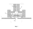
- FIG. 1 depicts a sectional view of a piece of working material 10 located in a hydroforming machine 20 prior to the shaping step of the pre-forming stage.
- the working material 10 comprises one or more flat sheets.
- a chamber 26 of the machine 20 is in an unpressurized state, i.e., at approximately normal atmospheric pressure.
- the chamber 26 includes a membrane 23.
- the chamber 26 is unpressurized such that the membrane 23 is not in contact with the working material 10.
- a known hydroform press for example, a TRIFORMTM-brand press made by Pryer Technology Group of Tulsa, Oklahoma, USA, could be employed for the pre-forming stage.
- a punch opening 33 which is overlaid by a draw ring 11 having an opening 13 in the center thereof.
- the opening 13 of the draw ring 11 is shaped so as to correspond with the shape of a top end 34 of the punch 32, and is smaller than the punch opening 33.
- the opening 13 of the draw ring 11 is carefully sized so as to be just barely larger than the dimensions of the punch 32, which is further discussed below.
- the difference in the widths of the opening 13 and the punch 32 may be on the order of 0.0100-0.0400 inches (0.0254-0.102 centimeters).
- the tight fit between the punch 32 and the opening 13 of the draw ring 11 prevents the working material 10 from being pushed down into the punch opening 33 when the chamber 26 is pressurized, provided that the punch 32 has previously been placed in a position to sufficiently fill and form a pressure seal within the punch opening 33. It should be understood that the draw ring 11 and punch 32 combination may be changeable so as to create pre-formed articles of different shapes and sizes.
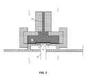
- FIG. 2 depicts a sectional view of the machine 20 after the chamber 26 has been partially pressurized via the addition of hydraulic fluid to the chamber 26 via fluid conduit 30.
- the hydraulic fluid may, for example, be an oil, though other known hydraulic fluids are also suitable.
- the chamber 26 may, for example, be initially pressurized to an amount between 250-500 p.s.i. (1.72*10 6 -3.45*10 6 Pascals), though higher or lower quantities of initial pressure could also be applied.
- the outer surface 24 of the membrane 23 comes in contact with and supplies pressure to the entire interior surface 12 of the working material 10.
- the pressure in the chamber 26 could be gradually increased as the working material 10 is shaped via a punch 32 of the machine 20.
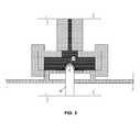
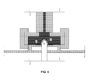
- FIGS. 3 and 4 depict sectional views of the machine 20 during and after the shaping step of the pre-forming stage, respectively.
- a hydraulically-driven punch 32 of the machine 20 is pressed upwardly against the exterior surface 14 of the working material 10.
- the punch 32 thus serves as a rigid, male shaping tool.
- a top end 34 of the punch 32 is provided in a shape that approximates the shape of the final shape of the article to be formed, i.e., a helmet.
- the shape of the top end 34 of the punch 32 may, but does not necessarily, represent the exact shape of the desired finished article.
- the hydrostatic pressure supplied by the membrane 23 to the interior surface 12 of the working material 10 is gradually increased, for example to a maximum pressure of between 1,000-15,000 p.s.i. (6.89*10 6 -1.03*10 8 Pascals), and thus shapes the working material 10 into a pre-formed article 16, as shown in FIG. 4 .
- the membrane 23 thus serves as a non-rigid, female shaping tool.
- the pressing step of the pre-forming stage is performed in the absence of added heat.
- the working material 10 comprises reinforced polyethylene fibers such as UHMWPE
- the absence of added heat during the pre-forming stage protects the fibers from heat exposure and resulting damage during this stage.
- a barrier may be placed between the top end 34 of the punch 32 and the exterior surface 14 of the working material 10. The barrier thus prevents the lubricant from coming in contact with the working material.
- the lubricant and/or barrier may be omitted entirely.
- the barrier itself may serve as a lubricant, for example where the barrier is made of a high-elongation plastic material or other suitable material.
- the pre-forming process may be performed in a series of "stepped" dynamic shaping stages, each dynamic shaping stage characterized by a deepening position of the punch 32 and a concurrent, increasing amount of pressure generated in the chamber 26.
- dynamic hydroforming for purposes of this application involves a punch within the chamber of the hydroform press that moves (i.e., does not remain static) in order to shape the desired article.
- some or all of the shaping stages may be separated by a static "dwell" shaping stage during which the position of the punch 32 does not move and the pressure in the chamber 26 is maintained at a constant value.
- the static "dwell" shaping stages serve to evacuate air from the chamber 26, thereby preventing dieseling of the air-i.e., combustion in the absence of a spark-from occurring in the chamber 26 and preventing damage to the working material 10 or machine 20 from occurring.
- the dwell periods may also serve to further consolidate together the layers of working material 10 and evacuate air from between these layers.
- the punch 32 has capabilities to perform punching of either "deep-draw” (e.g., to a depth of approximately 10 inches/25.4 centimeters) or "regular-draw” (e.g., to a depth of approximately 7 inches/17.8 centimeters).
- the deep-draw capability is used, though it should be understood that the regular draw capability could alternatively be used.
- the hydroforming machine in the pre-forming stage could be provided without a moving punch, and instead could comprise a stationary male or female die in the shape (or reciprocal shape) of the desired pre-formed article.
- This process of using a stationary die may be referred to as static hydroforming, as opposed to the process of dynamic hydroforming as discussed above with reference to the embodiment of FIGS. 1-5 .
- the membrane of the pressurized chamber would act to press the working material against the die and shape the working material into the desired pre-form shape.
- a combination of static and dynamic hydroforming steps could be employed.
- a punch may be initially positioned slightly within a chamber of a hydroform press such that it serves the role of a stationary die , thereby aiding to partially form the article when the chamber of the machine is pressurized (i.e., the static step).
- a membrane-less hydroform press could be used in place of a hydroform press having a membrane, in which embodiments the hydraulic material would come in direct contact with the working material, unless the working material is enclosed within a barrier as discussed above.
- Hydroforming is advantageous over traditional matched-metal molding (stamping) or drawing of working materials in that hydroforming provides greater dimensional stability, reduces wrinkling of the working materials, and reduces tooling and manufacturing costs. Deep-draw hydroforming is especially efficient at reducing wrinkling of the working materials as they are shaped. Hydroforming also eliminates the shear forces experienced during the stamping process as metal parts are moved past each other. Hydroforming achieves these desirable results by applying normal, isostatic pressure to all points along the surface of the working material that are interior to the chamber of the hydroforming machine.
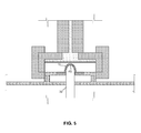
- FIG. 5 depicts a sectional view of the machine 20 after the shaping step of the pre-forming stage has been performed.
- the chamber 26 has been depressurized via removal of hydraulic fluid therefrom through the fluid conduit 30.
- the membrane 23 has shifted upwardly and is no longer in contact with the outer surface of the pre-formed article 16.
- the pre-forming stage is thereafter concluded by retracting the punch 32 back to its original position (as shown in FIGS. 1 and 2 ), and removing the pre-formed article 16 from the machine 20.
- the pre-formed article 16 is moved into a finishing machine where it is further consolidated and shaped into a final article and the resinous components of the working material are finally shaped or cured by applying pressure and added heat.
- the final-forming stage of the process can be performed using a variety of finishing machines, for example an autoclave, hydroclave, hydroform press, or matched-metal tooling.
- the pre-formed article 16 comprises multiple layers of UD pre-preg, for example, it is desirable to further consolidate these layers to remove any remaining air voids and bind or cure the matrices of the adjacent UD pre-preg layers together to form the finished article. Pressure and heat are therefore applied to the pre-formed article 16 in the final-forming stage in order to consolidate and shape the pre-formed article 16 into its final shape and, if necessary, cure the matrix material.
- a static hydroform press is used as the finishing machine 40.
- the pre-formed article 16 is placed in a chamber 46 of the finishing machine 40 around a male die 50.
- the male die 50 is provided in the desired shape of the fully formed article, which in this embodiment is a helmet.
- a membrane 43 located in the chamber 46 comes in contact with and applies pressure to the pre-formed article 16.
- the pre-formed article is pressed against an outer surface 52 of the male die 50, thereby shaping the pre-formed article 16 into a finished article 18.
- the male die 5 0 could be replaced by a female die or cutout in the approximate shape of the desired article.
- the membrane 43 would act as the male component that presses the pre-formed article 16 into the desired shape against the female die or cutout. This process may be referred to as bag molding or bag pressure molding.
- FIG. 6 depicts a sectional view of the pre-formed article 16 located in the finishing machine 40 prior to the final shaping step of the final-forming stage.
- the chamber 46 of the machine 40 is in an unpressurized state, i.e., at approximately normal atmospheric pressure.
- the membrane 43 is not in contact with the pre-formed article 16.
- a suitable, known hydroform press could be employed for the final-forming stage. It is also possible that the same hydroform press could be used in both the pre-forming stage and the final-forming stage, within the scope of the herein disclosed inventive concept(s).
- FIG. 7 depicts a sectional view of the machine 40 after the chamber 46 has been pressurized via the addition of hydraulic fluid to the chamber 46 through fluid conduit 48.
- the chamber 46 may, for example, be partially pressurized to a pressure of between 2,500-5,000 p.s.i. (1.72*10 7 -3.45*10 7 Pascals) though higher or lower quantities of pressure could be applied, depending on, for example, the characteristics of the materials used.
- a "stepped" pressurizing process, wherein the pressure in the chamber 46 is gradually increased (either with or without intermittent "dwell” steps) may also be employed at the final-forming stage. Referring back to the embodiment of FIG.
- the fluid in the chamber 46 and/or the die 50 is also heated, as necessary, to achieve a critical temperature for final shaping or curing of the matrix material of the UD pre-preg layers.
- the critical temperature may be the melting temperature of the particular thermoplastic.
- the fluid in the chamber 46 and/or the die 50 may be heated to at or above the melting temperature of the particular thermoplastic so that it transitions to a liquid state in which the matrix material flows and fills the voids between the reinforcing fibers of the pre-preg layers.
- an additional curing step for the plastic material may or may not be necessary.
- the critical temperature may be the curing temperature for the selected thermoset resin.
- the fluid in the chamber 46 and/or the die 50 may be heated to a temperature sufficient to cure the matrix material into the desired solid shape. It will be readily understood by those having ordinary skill in the art that the appropriate heating (i.e., critical) temperature and heat-exposure time are dependent on the materials used in the pre-preg layers.
- the outer surface 44 of the membrane 43 supplies pressure to the outer surface 47 of the pre-formed article 16.
- the inner surface 45 of the pre-formed article 16 presses against the male die 50.
- the male die 50 thus determines the shape taken on by the pre-formed article 16 as the membrane 43 is pressed against the outer surface 47 of the pre-formed article 16.
- FIG. 8 depicts a sectional view of the machine 40 after the shaping step of the final-forming stage has been performed.
- the chamber 46 has been depressurized via removal of hydraulic fluid therefrom through the fluid conduit 48.
- the membrane 43 has moved upwardly and is no longer in contact with the outer surface 47 of the pre-formed article 16, which has now been fully shaped into a finished article 18.
- the final-forming stage is thereupon concluded.
- the finished article 18 can then be removed from the machine 40.
Landscapes
- Engineering & Computer Science (AREA)
- Mechanical Engineering (AREA)
- Chemical & Material Sciences (AREA)
- Composite Materials (AREA)
- Shaping Metal By Deep-Drawing, Or The Like (AREA)
- Forging (AREA)
- Casting Or Compression Moulding Of Plastics Or The Like (AREA)
- Manufacture Of Alloys Or Alloy Compounds (AREA)
Abstract
Description
- The present inventive concept(s) relate to the field of forming or shaping articles, in particular forming or shaping articles using a hydroforming process for at least one of the forming or shaping steps.
- Existing hydroforming processes use high-pressure hydraulic fluid to compress a piece of working material against a stationary die or moving punch to form an article of a particular shape. It is known in the art to use a hydroforming process to shape complex structures from pieces of sheet metal or composite materials, for example continuous-fiber or woven-fiber composites. Due to the even application of hydrostatic pressure supplied by the hydroforming process, it is known to provide the advantage of reducing the presence of wrinkles and folds in the shaped working material.
- Formation of a multi-layered continuous-fiber or woven-fiber composite requires a curing step wherein pressure and heat are applied to the layers of composite material in order to compress and fuse together the resin base of the layers of composite material, remove air voids from between the layers, and finally cure or set the layers of composite material together. However, typical fiber materials suitable for ballistic composite sheets, for example polyethylene, are known to degrade when subject to high heat for an extended period of time.
- In addition, the known benefits of using a hydroforming process to shape composite structures allows the user to avoid placing relief cuts into the body of the flat layers of composite material prior to the forming process, which is necessary when using other known shaping methods in order to reduce wrinkling of the layers of composite material during the formation process. A drawback to placing relief cuts into the flat layers is that the strength of the layers of composite material, in particular the strength of the reinforcing fibers thereof, is reduced when the composite layers (i.e., the reinforcing fibers) are cut. Thus, it is desirable to avoid cutting into the body of the layers of composite material in order to maximize the strength of these layers. The use of a hydroforming process during the pre-forming stage makes avoidance of cutting into the body of the flat composite layers possible. The prior art also discloses mechanical clamping of the working material within the chamber of the hydroform press prior to the pressurization step in order to prevent wrinkling of the working material during the hydroforming process.
- Therefore, it is desirable to have a process for forming or shaping articles which improves the formed shape of the article, while reducing the duration of exposure to heat experienced by the reinforcement fiber materials and avoiding the need to provide relief cuts into the body of the layers of the composite material, all while not significantly impacting the costs associated with production of the final article.
-
- In a first respect, the present application discloses a method of shaping a flat working material into a composite product having a final shape, the method comprising: (a) in the absence of added heat, consolidating and shaping the working material into a pre-form shape using a dynamic hydroforming process that employs a rigid, male-shaped tool and a non-rigid, female-shaped tool; and (b) in the presence of added heat, further consolidating and shaping the working material into the final shape using at least one additional rigid forming tool.
- In another respect, the present application discloses a method of shaping a working material into a composite product having a final shape, the working material including a resinous matrix material, the method comprising: (a)consolidating and shaping the working material into a pre-form shape using a deep-draw hydroforming process that employs a rigid, male-shaped tool and a non-rigid, female-shaped tool, the consolidating and shaping occurring below a critical temperature of the resinous matrix material; and(b) further consolidating and shaping the working material into the final shape using at least one additional rigid forming tool, the further consolidating and shaping occurring at or above the critical temperature.
- In still another respect, the present application discloses a method of shaping a flat working material into a composite product having a final shape, the method comprising: (a) in the absence of added heat, consolidating and shaping the working material into a pre-form shape using a dynamic hydroforming process that employs a rigid tool and a non-rigid tool; and (b) in the presence of added heat, further consolidating and shaping the working material into the final shape using at least one additional rigid forming tool.
- The herein disclosed inventive concepts will hereinafter be described in conjunction with the appended drawing figures wherein like numerals denote like elements.
-
FIG. 1 is a sectional view of an unshaped working material located in a hydroforming machine in an unpressurized state prior to a shaping step of a pre-forming stage; -
FIG. 2 is a sectional view of the hydroforming machine ofFIG. 1 in a pressurized state prior to the shaping step of the pre-forming stage; -
FIG. 3 is a sectional view of the hydroforming machine ofFIG. 1 in a pressurized state during the shaping step of the pre-forming stage; -
FIG. 4 is a sectional view of the hydroforming machine ofFIG. 1 in a pressurized state following the shaping step of the pre-forming stage; -
FIG. 5 is a sectional view of the hydroforming machine ofFIG. 1 in an unpressurized state following the shaping step of the pre-forming stage; -
FIG. 6 is a sectional view of the pre-formed working material located in a finishing machine in an unpressurized state prior to the final-forming stage of the working material; -
FIG. 7 is a sectional view of the finishing machine ofFIG. 6 in a pressurized state during the shaping step of the final-forming stage; and -
FIG. 8 is a sectional view of the finishing machine ofFIG. 6 in an unpressurized state following the shaping step of the final-forming stage. - The ensuing detailed description provides preferred exemplary embodiments only, and is not intended to limit the scope, applicability, or configuration of the herein taught inventive concept(s). Rather, the ensuing detailed description of the preferred exemplary embodiments will provide those skilled in the art with an enabling description for implementing the preferred exemplary embodiments of the inventive concept(s). It should be understood that various changes may be made in the function and arrangement of elements without departing from the spirit and scope of the inventive concept(s), as set forth in the appended claims.
- To aid in describing the inventive concept(s), directional terms may be used in the specification and claims to describe portions of the present inventive concept(s) (e.g., upper, lower, left, right, etc.). These directional definitions are merely intended to assist in describing and claiming the inventive concept(s) and are not intended to limit the inventive concept(s) in any way. In addition, reference numerals that are introduced in the specification in association with a drawing figure may be repeated in one or more subsequent figures without additional description in the specification in order to provide context for other features.
- In this application, "pre-forming" is defined as shaping of a piece of working material to approximate a desired finished shape of an article.
- In this application, "working material" is defined as one or more layers of material from which an article of manufacture is formed, for example a composite material. The composite material is preferably prepreg sheets, as further discussed below. The working material may be flat, or of any other initial shape, for purposes of the present disclosure.
- The present application discloses a process for forming or shaping composite articles comprising two primary stages: (1) a first stage comprising pre-forming a piece of working material by applying pressure in the absence of added heat to approximate a desired finished shape of an article (i.e., a "pre-form shape"); and (2) a second stage comprising the final shaping or forming of the piece of working material into an article of final shape by applying pressure and added heat. Unlike in the prior art, the present process does not require a mechanical clamping device to support the position of the working material within the chamber of the hydroform press during the hydroforming stage. In the present process, a membrane of the hydroform press provides all of the clamping force applied to the working material during the hydroforming stage.
- In one embodiment according to the present inventive concept, the desired finished article is a helmet having ballistic qualities for use by, for example, pilots and infantrymen. In this embodiment, the working material may comprise multiple sheets of composite fibers that are pre-impregnated within a matrix material or resin (hereinafter referred to as "pre-preg" sheets). The matrix of the pre-preg sheets is used to maintain the relative orientation of the fibers within the sheets of pre-preg, provide a foundation for the structural integrity of the pre-preg sheets, and-as further discussed below-bond multiple sheets of pre-preg to each other during a curing process. In some embodiments according to the present inventive concept(s), the pre-preg sheets may have a flat initial shape.
- In some embodiments according to the present inventive concept(s), the composite fibers of the pre-preg sheets may be comprised of ultra high molecular weight polyethylene ("UHMWPE"). Notable commercial examples of UHMWPE include SPECTRA® made by Honeywell International Inc., and DYNEEMA® made by Royal DSM N.V., both of which are sold in the form of pre-preg sheets having uni-directional fiber orientations ("UD pre-preg").
- In alternate embodiments, the working material could comprise a metallic material, an aramid material, a carbon material, a plastic-based composite material (which may be UD pre-preg), or any combinations thereof. In some embodiments, the working material could comprise a fibrous material (e.g., pre-preg, aramid) and a non-fibrous material (e.g., carbon, metal). In additional alternate embodiments, the working material could comprise at least one pre-preg sheet, at least one layer of an aramid-based composite material, and at least one layer of a carbon-based composite material which are configured as a "stack-up" or "lay-up" having the pre-preg sheet(s) at the core, the at least one layer of aramid-based composite material located on one or both sides of the pre-preg sheet(s), and the at least one layer of carbon-based composite material forming the outermost layer(s) of the stack-up. In an exemplary embodiment, the at least one layer of aramid-based composite material comprises first and second aramid-based composite layers and the at least one layer of carbon-based composite material comprises first and second carbon-based composite layers, and the working material is arranged into a stacked configuration having the following order from a top layer of the stacked configuration to a bottom layer of the stacked configuration: the first carbon-based composite layer; the first aramid-based composite layer; the at least one prepreg sheet; the second aramid-based composite layer; and the second carbon-based composite layer.
- In further alternate embodiments, the working material may comprise a first uni-directional prepreg layer having a first fiber orientation and a second uni-directional prepreg layer having a second fiber orientation, wherein the first and second fiber orientations are orthogonal (i.e., arranged at 90 degrees to each other).
- One notable challenge associated with shaping or forming articles from sheets of pre-preg is to translate the performance characteristics of the working material to the desired final article while minimizing degradation in the performance characteristics of the working material as much as possible. Further, it is desirable to achieve this goal while not significantly increasing the costs associated with production of the final article.
- When a hydroform press is not used to pre-form a composite material, or if the pre-forming stage is omitted, it may be necessary to place relief cuts into the bodies of the flat layers of composite material prior to the forming process so as to reduce wrinkling of the layers of composite material during the pre-forming process. One drawback to placing these relief cuts into the bodies of the flat layers of composite material is that the strength of the layers of composite material, in particular the strength of the reinforcing fibers thereof, is reduced when the reinforcing fibers of each layer are trimmed. The reinforcing fibers of the layers of composite material maintain their maximum integrity when they are maintained at their full, uncut length. Thus, it is desirable to avoid making relief cuts into the layers of composite material in order to maximize the strength of these layers. The use of a hydroform press in the pre-forming stage makes it unnecessary to place these relief cuts in the layers of composite material.
- In accordance with the present inventive concept(s), prior to the pre-forming stage, it may be desirable to pre-trim the flat layers of composite material into an appropriate planar shape that corresponds with the non-planar shape of the desired pre-formed article. For example, if the desired pre-formed article has an approximately hemi-spherical shape, then the flat layers of composite material may be pre-trimmed into circular shapes prior to the pre-forming process. Similarly, if the desired pre-formed article has an ovoid shape, then the flat layers of composite material may be cut into the corresponding oval shape prior to the pre-forming process. It should be made clear, as noted in the previous paragraph, that in some embodiments no cuts are required to be made into the body of the flat layers of composite material. In other words, in some embodiments, no cuts are made into the perimeter of the pre-trimmed shape of the flat layers of composite material. In alternate embodiments, cuts may be made into the body of the flat layers of composite material, for example where it is desirable to reduce the quantity of waste materials produced as a result of the pre-forming process.
- Referring now generally to
FIGS. 1-8 , an exemplary method for forming an article will hereinafter be described.FIGS. 1-5 depict steps according to the first, i.e., pre-forming stage of the method, andFIGS. 6-8 depict steps according to the second, i.e., final-forming stage of the method. -
FIG. 1 depicts a sectional view of a piece of workingmaterial 10 located in ahydroforming machine 20 prior to the shaping step of the pre-forming stage. In this embodiment, the workingmaterial 10 comprises one or more flat sheets. At this step, achamber 26 of themachine 20 is in an unpressurized state, i.e., at approximately normal atmospheric pressure. Along its bottom end thechamber 26 includes amembrane 23. At this step, thechamber 26 is unpressurized such that themembrane 23 is not in contact with the workingmaterial 10. A known hydroform press, for example, a TRIFORM™-brand press made by Pryer Technology Group of Tulsa, Oklahoma, USA, could be employed for the pre-forming stage. At the bottom end of thechamber 26 is apunch opening 33, which is overlaid by adraw ring 11 having anopening 13 in the center thereof. Theopening 13 of thedraw ring 11 is shaped so as to correspond with the shape of atop end 34 of thepunch 32, and is smaller than thepunch opening 33. Theopening 13 of thedraw ring 11 is carefully sized so as to be just barely larger than the dimensions of thepunch 32, which is further discussed below. For example, the difference in the widths of theopening 13 and thepunch 32 may be on the order of 0.0100-0.0400 inches (0.0254-0.102 centimeters). The tight fit between thepunch 32 and theopening 13 of thedraw ring 11 prevents the workingmaterial 10 from being pushed down into thepunch opening 33 when thechamber 26 is pressurized, provided that thepunch 32 has previously been placed in a position to sufficiently fill and form a pressure seal within thepunch opening 33. It should be understood that thedraw ring 11 and punch 32 combination may be changeable so as to create pre-formed articles of different shapes and sizes. -
FIG. 2 depicts a sectional view of themachine 20 after thechamber 26 has been partially pressurized via the addition of hydraulic fluid to thechamber 26 viafluid conduit 30. The hydraulic fluid may, for example, be an oil, though other known hydraulic fluids are also suitable. During the pre-forming stage, thechamber 26 may, for example, be initially pressurized to an amount between 250-500 p.s.i. (1.72*106-3.45*106 Pascals), though higher or lower quantities of initial pressure could also be applied. As a result of pressurization of thechamber 26, the outer surface 24 of themembrane 23 comes in contact with and supplies pressure to the entireinterior surface 12 of the workingmaterial 10. As noted below, in some embodiments, the pressure in thechamber 26 could be gradually increased as the workingmaterial 10 is shaped via apunch 32 of themachine 20. -
FIGS. 3 and4 depict sectional views of themachine 20 during and after the shaping step of the pre-forming stage, respectively. During the shaping step, a hydraulically-drivenpunch 32 of themachine 20 is pressed upwardly against theexterior surface 14 of the workingmaterial 10. Thepunch 32 thus serves as a rigid, male shaping tool. In this embodiment, atop end 34 of thepunch 32 is provided in a shape that approximates the shape of the final shape of the article to be formed, i.e., a helmet. The shape of thetop end 34 of thepunch 32 may, but does not necessarily, represent the exact shape of the desired finished article. As thepunch 32 is moved upwardly against theexterior surface 14 of the workingmaterial 10 and into thechamber 26, the hydrostatic pressure supplied by themembrane 23 to theinterior surface 12 of the workingmaterial 10 is gradually increased, for example to a maximum pressure of between 1,000-15,000 p.s.i. (6.89*106-1.03*108 Pascals), and thus shapes the workingmaterial 10 into apre-formed article 16, as shown inFIG. 4 . Themembrane 23 thus serves as a non-rigid, female shaping tool. In this embodiment, the pressing step of the pre-forming stage is performed in the absence of added heat. As noted above, where the workingmaterial 10 comprises reinforced polyethylene fibers such as UHMWPE, the absence of added heat during the pre-forming stage protects the fibers from heat exposure and resulting damage during this stage. - In some embodiments (not shown), it may be desirable to lubricate the
top end 34 of thepunch 32 so that movement of thepunch 32 against the workingmaterial 10 is aided. In some embodiments, it may not be desirable to permit the lubricant to come in direct contact with theexterior surface 14 of the workingmaterial 10, for example where it is not desirable for the lubricant to be absorbed by the workingmaterial 10. In these embodiments, a barrier may be placed between thetop end 34 of thepunch 32 and theexterior surface 14 of the workingmaterial 10. The barrier thus prevents the lubricant from coming in contact with the working material. In alternate embodiments, the lubricant and/or barrier may be omitted entirely. In further alternate embodiments, the barrier itself may serve as a lubricant, for example where the barrier is made of a high-elongation plastic material or other suitable material. - The pre-forming process may be performed in a series of "stepped" dynamic shaping stages, each dynamic shaping stage characterized by a deepening position of the
punch 32 and a concurrent, increasing amount of pressure generated in thechamber 26. In other words, "dynamic hydroforming" for purposes of this application involves a punch within the chamber of the hydroform press that moves (i.e., does not remain static) in order to shape the desired article. In some embodiments according to the present inventive concept(s), some or all of the shaping stages may be separated by a static "dwell" shaping stage during which the position of thepunch 32 does not move and the pressure in thechamber 26 is maintained at a constant value. The static "dwell" shaping stages serve to evacuate air from thechamber 26, thereby preventing dieseling of the air-i.e., combustion in the absence of a spark-from occurring in thechamber 26 and preventing damage to the workingmaterial 10 ormachine 20 from occurring. The dwell periods may also serve to further consolidate together the layers of workingmaterial 10 and evacuate air from between these layers. - In the embodiment shown in
FIGS 1-5 , thepunch 32 has capabilities to perform punching of either "deep-draw" (e.g., to a depth of approximately 10 inches/25.4 centimeters) or "regular-draw" (e.g., to a depth of approximately 7 inches/17.8 centimeters). In this embodiment, the deep-draw capability is used, though it should be understood that the regular draw capability could alternatively be used. In alternate embodiments (not shown), the hydroforming machine in the pre-forming stage could be provided without a moving punch, and instead could comprise a stationary male or female die in the shape (or reciprocal shape) of the desired pre-formed article. This process of using a stationary die may be referred to as static hydroforming, as opposed to the process of dynamic hydroforming as discussed above with reference to the embodiment ofFIGS. 1-5 . In either the male or female static hydroforming alternate embodiments, the membrane of the pressurized chamber would act to press the working material against the die and shape the working material into the desired pre-form shape. In further alternate embodiments, a combination of static and dynamic hydroforming steps could be employed. For example, a punch may be initially positioned slightly within a chamber of a hydroform press such that it serves the role of a stationary die , thereby aiding to partially form the article when the chamber of the machine is pressurized (i.e., the static step). Later, the punch could be moved as additional shaping of the article (and, optionally, changes in the pressurization of the chamber) occurs (i.e., the dynamic step). In still further alternate embodiments, a membrane-less hydroform press could be used in place of a hydroform press having a membrane, in which embodiments the hydraulic material would come in direct contact with the working material, unless the working material is enclosed within a barrier as discussed above. - Hydroforming is advantageous over traditional matched-metal molding (stamping) or drawing of working materials in that hydroforming provides greater dimensional stability, reduces wrinkling of the working materials, and reduces tooling and manufacturing costs. Deep-draw hydroforming is especially efficient at reducing wrinkling of the working materials as they are shaped. Hydroforming also eliminates the shear forces experienced during the stamping process as metal parts are moved past each other. Hydroforming achieves these desirable results by applying normal, isostatic pressure to all points along the surface of the working material that are interior to the chamber of the hydroforming machine.
-
FIG. 5 depicts a sectional view of themachine 20 after the shaping step of the pre-forming stage has been performed. During this step, thechamber 26 has been depressurized via removal of hydraulic fluid therefrom through thefluid conduit 30. As a result, themembrane 23 has shifted upwardly and is no longer in contact with the outer surface of thepre-formed article 16. In this embodiment, the pre-forming stage is thereafter concluded by retracting thepunch 32 back to its original position (as shown inFIGS. 1 and2 ), and removing thepre-formed article 16 from themachine 20. - At the second stage of the method according to the present inventive concept(s), the
pre-formed article 16 is moved into a finishing machine where it is further consolidated and shaped into a final article and the resinous components of the working material are finally shaped or cured by applying pressure and added heat. The final-forming stage of the process can be performed using a variety of finishing machines, for example an autoclave, hydroclave, hydroform press, or matched-metal tooling. - If the
pre-formed article 16 comprises multiple layers of UD pre-preg, for example, it is desirable to further consolidate these layers to remove any remaining air voids and bind or cure the matrices of the adjacent UD pre-preg layers together to form the finished article. Pressure and heat are therefore applied to thepre-formed article 16 in the final-forming stage in order to consolidate and shape thepre-formed article 16 into its final shape and, if necessary, cure the matrix material. - In the embodiment shown in
FIGS. 6-8 , a static hydroform press is used as the finishingmachine 40. As shown inFIG. 6 , thepre-formed article 16 is placed in achamber 46 of the finishingmachine 40 around amale die 50. The male die 50 is provided in the desired shape of the fully formed article, which in this embodiment is a helmet. As discussed below, when thechamber 46 is pressurized, amembrane 43 located in thechamber 46 comes in contact with and applies pressure to thepre-formed article 16. As a result, the pre-formed article is pressed against anouter surface 52 of themale die 50, thereby shaping thepre-formed article 16 into afinished article 18. In alternate embodiments, the male die 5 0 could be replaced by a female die or cutout in the approximate shape of the desired article. In those embodiments, themembrane 43 would act as the male component that presses thepre-formed article 16 into the desired shape against the female die or cutout. This process may be referred to as bag molding or bag pressure molding. -
FIG. 6 depicts a sectional view of thepre-formed article 16 located in the finishingmachine 40 prior to the final shaping step of the final-forming stage. At this step, thechamber 46 of themachine 40 is in an unpressurized state, i.e., at approximately normal atmospheric pressure. At this step, themembrane 43 is not in contact with thepre-formed article 16. A suitable, known hydroform press could be employed for the final-forming stage. It is also possible that the same hydroform press could be used in both the pre-forming stage and the final-forming stage, within the scope of the herein disclosed inventive concept(s). -
FIG. 7 depicts a sectional view of themachine 40 after thechamber 46 has been pressurized via the addition of hydraulic fluid to thechamber 46 throughfluid conduit 48. Thechamber 46 may, for example, be partially pressurized to a pressure of between 2,500-5,000 p.s.i. (1.72*107-3.45*107 Pascals) though higher or lower quantities of pressure could be applied, depending on, for example, the characteristics of the materials used. A "stepped" pressurizing process, wherein the pressure in thechamber 46 is gradually increased (either with or without intermittent "dwell" steps) may also be employed at the final-forming stage. Referring back to the embodiment ofFIG. 7 , at this time, the fluid in thechamber 46 and/or thedie 50 is also heated, as necessary, to achieve a critical temperature for final shaping or curing of the matrix material of the UD pre-preg layers. Where the matrix material is a thermoplastic, for example, the critical temperature may be the melting temperature of the particular thermoplastic. In these (e.g., thermoplastic) embodiments, the fluid in thechamber 46 and/or the die 50 may be heated to at or above the melting temperature of the particular thermoplastic so that it transitions to a liquid state in which the matrix material flows and fills the voids between the reinforcing fibers of the pre-preg layers. Where a thermoplastic is used, an additional curing step for the plastic material may or may not be necessary. In alternate embodiments, for example where the matrix material is a thermoset, the critical temperature may be the curing temperature for the selected thermoset resin. In these embodiments, the fluid in thechamber 46 and/or the die 50 may be heated to a temperature sufficient to cure the matrix material into the desired solid shape. It will be readily understood by those having ordinary skill in the art that the appropriate heating (i.e., critical) temperature and heat-exposure time are dependent on the materials used in the pre-preg layers. - Referring back to
FIG. 7 , as a result of pressurization of thechamber 46 of themachine 40, theouter surface 44 of themembrane 43 supplies pressure to theouter surface 47 of thepre-formed article 16. As themembrane 43 supplies pressure to theouter surface 47 of thepre-formed article 16, theinner surface 45 of thepre-formed article 16 presses against the male die 50. The male die 50 thus determines the shape taken on by thepre-formed article 16 as themembrane 43 is pressed against theouter surface 47 of thepre-formed article 16. -
FIG. 8 depicts a sectional view of themachine 40 after the shaping step of the final-forming stage has been performed. During this step, thechamber 46 has been depressurized via removal of hydraulic fluid therefrom through thefluid conduit 48. As a result, themembrane 43 has moved upwardly and is no longer in contact with theouter surface 47 of thepre-formed article 16, which has now been fully shaped into afinished article 18. In this embodiment, the final-forming stage is thereupon concluded. Thefinished article 18 can then be removed from themachine 40. - While the principles of the herein taught inventive concept(s) have been described above in connection with preferred embodiments, it is to be clearly understood that this description is made only by way of example and not as a limitation of the scope of the inventive concept(s).
- Further aspects of the present inventive concept(s) include:
- Aspect 1: A method of shaping a flat working material into a composite product having a final shape, the method comprising:(a) in the absence of added heat, consolidating and shaping the working material into a pre-form shape using a dynamic hydroforming process that employs a rigid, male-shaped tool and a non-rigid, female-shaped tool; and (b) in the presence of added heat, further consolidating and shaping the working material into the final shape using at least one additional rigid forming tool.
- Aspect 2: The method of Aspect 1, wherein step (a) comprises a series of dynamic shaping stages, each dynamic shaping stage including deepening the position of the rigid, male-shaped tool relative to a first surface of the working material and applying pressure to a second surface of the working material.
- Aspect 3: The method of Aspect 2, wherein each dynamic shaping stage includes applying increased pressure to the second surface of the working material.
- Aspect 4: The method of any one of Aspects 1-3, wherein the non-rigid, female-shaped tool provides all of the clamping force applied to the working material during step (a).
- Aspect 5: The method of any one of Aspects 1-3, wherein step (a) does not employ a mechanical clamping device.
- Aspect 6: The method of any one of Aspects 1-5, wherein a draw ring is placed between the rigid, male-shaped tool and the working material prior to step (a).
- Aspect 7: The method of any one of Aspects 1-6, wherein step (a) occurs in a first forming machine and step (b) occurs in a second forming machine.
- Aspect 8: The method of Aspect 7, wherein the second forming machine is a hydroform press.
- Aspect 9: The method of any one of Aspects 1-8, wherein the at least one additional rigid forming tool is male-shaped.
- Aspect 10: The method of any one of Aspects 1-9, wherein the at least one additional rigid forming tool does not move during step (b).
- Aspect 11: The method of any one of Aspects 1-8 or
Aspect 10, wherein the at least one additional rigid forming tool is female-shaped. - Aspect 12: The method of any one of Aspects 1-8, wherein the at least one additional rigid forming tool comprises a pair of matched metal molds.
- Aspect 13: The method of any one of Aspects 1-12, wherein the working material comprises a fibrous material and a non-fibrous material.
- Aspect 14: The method of any one of Aspects 1-13, wherein the working material comprises at least one prepreg sheet, the at least one prepreg sheet comprising a plurality of composite fibers.
- Aspect 15: The method of
Aspect 14, wherein the plurality of composite fibers are comprised of ultra high molecular weight polyethylene. - Aspect 16: The method of any one of Aspects 13-15, wherein the working material further comprises at least one layer of aramid-based composite material and at least one layer of carbon-based composite material.
- Aspect 17: The method of
Aspect 16, wherein the at least one layer of aramid-based composite material comprises first and second aramid-based composite layers and the at least one layer of carbon-based composite material comprises first and second carbon-based composite layers, and the working material is arranged into a stacked configuration having the following order from a top layer of the stacked configuration to a bottom layer of the stacked configuration: the first carbon-based composite layer; the first aramid-based composite layer; the at least one prepreg sheet; the second aramid-based composite layer; and the second carbon-based composite layer. - Aspect 18: The method of any one of Aspects 1-17, wherein the working material comprises a first uni-directional prepreg layer having a first fiber orientation and a second uni-directional prepreg layer having a second fiber orientation, wherein the first and second fiber orientations are orthogonal to each other.
- Aspect 19: The method of any one of Aspects 1-18, wherein a maximum pressure applied during step (a) is at least double a maximum pressure applied during step (b).
- Aspect 20: A method of shaping a working material into a composite product having a final shape, the working material including a resinous matrix material, the method comprising: (a) consolidating and shaping the working material into a pre-form shape using a deep-draw hydroforming process that employs a rigid, male-shaped tool and a non-rigid, female-shaped tool, the consolidating and shaping occurring below a critical temperature of the resinous matrix material; and (b) further consolidating and shaping the working material into the final shape using at least one additional rigid forming tool, the further consolidating and shaping occurring at or above the critical temperature.
- Aspect 21: The method of
Aspect 20, wherein step (a) occurs in the absence of added heat. - Aspect 22: A method of shaping a flat working material into a composite product having a final shape, the method comprising: (a) in the absence of added heat, consolidating and shaping the working material into a pre-form shape using a dynamic hydroforming process that employs a rigid tool and a non-rigid tool; and (b) in the presence of added heat, further consolidating and shaping the working material into the final shape using at least one additional rigid forming tool.
Claims (15)
- A method of shaping a flat working material (10) into a composite product having a final shape, the method comprising:(a) consolidating and shaping the working material (10) into a pre-form shape (16) using a hydroforming process that employs a rigid tool (32) and a non-rigid tool (23); and(b) in the presence of added heat, further consolidating and shaping the working material (10) into the final shape using at least one additional rigid forming tool (50),wherein step (a) is performed in the absence of added heat.
- The method of any preceding claim, wherein pressure is applied during step (a) and step (b).
- The method of claim 1 or 2, wherein step (a) uses a dynamic hydroforming process comprising a series of dynamic shaping stages, each dynamic shaping stage including deepening the position of the rigid tool relative to a first surface of the working material and applying pressure to a second surface of the working material.
- The method of claim 1 or 2, wherein step (a) uses a static hydroforming process wherein the rigid tool remains stationary and does not move and wherein the pressure is maintained at a constant value.
- The method of any preceding claim, wherein the working material comprises multiple sheets of composite fibres.
- The method of claim 5, wherein the multiple sheets of composite material are preimpregnated with a matrix or resin.
- The method of any preceding claim, wherein the working material comprises a metallic material, an aramid material, a carbon material, a plastics-based composite material, or any combinations thereof.
- The method of any preceding claim, wherein the working material comprises at least one preimpregnated sheet, at least one layer of aramid-based composite material, and at least one layer of a carbon-based composite material, wherein the working material is configured such that the at least one preimpregnated sheet is at the core, the at least one layer of aramid based composite material is located on one or both sides of the at least one preimpregnated sheet, and the at least one layer of carbon-based composite material forms the outermost layer.
- The method of any preceding claim, wherein said rigid tool is a rigid, male-shaped tool and said non-rigid tool is a non-rigid, female-shaped tool, wherein the rigid, male-shaped tool is a punch and the non-rigid, female-shaped tool is a membrane.
- The method of claim 9, wherein the shape of the top end of the punch approximates the shape of the final article to be formed.
- The method of claim 9 or 10, further comprising the step of lubricating the top end of the punch.
- The method of claim 9, 10 or 11, wherein a barrier is placed between the top end of the punch and the exterior surface of the working material.
- The method of any one of claims 1 to 8, wherein the hydroforming process uses a stationary male or female die.
- Apparatus comprising means for performing the method of any preceding claim, the apparatus comprising a first forming machine for performing step (a), and a second forming machine for performing step (b).
- The apparatus of claim 14, wherein the second forming machine is a hydroform press comprising:a chamber for accommodating a working material, wherein a bottom end of the chamber includes a membrane and a punch opening, and a draw ring is provided between the punch opening and the membrane; anda fluid conduit for the addition of hydraulic fluid to the chamber.
Priority Applications (2)
| Application Number | Priority Date | Filing Date | Title |
|---|---|---|---|
| EP20176175.6A EP3756868B1 (en) | 2010-06-23 | 2011-06-23 | Process and apparatus for shaping or forming articles |
| PL14183085T PL2851184T3 (en) | 2010-06-23 | 2011-06-23 | Process and apparatus for shaping or forming articles |
Applications Claiming Priority (3)
| Application Number | Priority Date | Filing Date | Title |
|---|---|---|---|
| US35779910P | 2010-06-23 | 2010-06-23 | |
| PCT/US2011/041648 WO2011163486A2 (en) | 2010-06-23 | 2011-06-23 | Process for shaping or forming articles |
| EP11729015.5A EP2605900B1 (en) | 2010-06-23 | 2011-06-23 | Process for shaping a flat working material into a composite product |
Related Parent Applications (2)
| Application Number | Title | Priority Date | Filing Date |
|---|---|---|---|
| EP11729015.5A Division EP2605900B1 (en) | 2010-06-23 | 2011-06-23 | Process for shaping a flat working material into a composite product |
| EP11729015.5A Division-Into EP2605900B1 (en) | 2010-06-23 | 2011-06-23 | Process for shaping a flat working material into a composite product |
Related Child Applications (1)
| Application Number | Title | Priority Date | Filing Date |
|---|---|---|---|
| EP20176175.6A Division EP3756868B1 (en) | 2010-06-23 | 2011-06-23 | Process and apparatus for shaping or forming articles |
Publications (2)
| Publication Number | Publication Date |
|---|---|
| EP2851184A1 true EP2851184A1 (en) | 2015-03-25 |
| EP2851184B1 EP2851184B1 (en) | 2020-05-27 |
Family
ID=44627714
Family Applications (3)
| Application Number | Title | Priority Date | Filing Date |
|---|---|---|---|
| EP20176175.6A Active EP3756868B1 (en) | 2010-06-23 | 2011-06-23 | Process and apparatus for shaping or forming articles |
| EP11729015.5A Active EP2605900B1 (en) | 2010-06-23 | 2011-06-23 | Process for shaping a flat working material into a composite product |
| EP14183085.1A Active EP2851184B1 (en) | 2010-06-23 | 2011-06-23 | Process and apparatus for shaping or forming articles |
Family Applications Before (2)
| Application Number | Title | Priority Date | Filing Date |
|---|---|---|---|
| EP20176175.6A Active EP3756868B1 (en) | 2010-06-23 | 2011-06-23 | Process and apparatus for shaping or forming articles |
| EP11729015.5A Active EP2605900B1 (en) | 2010-06-23 | 2011-06-23 | Process for shaping a flat working material into a composite product |
Country Status (11)
| Country | Link |
|---|---|
| US (1) | US9216523B2 (en) |
| EP (3) | EP3756868B1 (en) |
| KR (1) | KR101858767B1 (en) |
| CN (1) | CN103153591A (en) |
| BR (1) | BR112012032710B1 (en) |
| CO (1) | CO6680617A2 (en) |
| ES (3) | ES2525015T3 (en) |
| IL (1) | IL223676A (en) |
| MX (1) | MX336415B (en) |
| PL (3) | PL2605900T3 (en) |
| WO (1) | WO2011163486A2 (en) |
Families Citing this family (16)
| Publication number | Priority date | Publication date | Assignee | Title |
|---|---|---|---|---|
| US9307803B1 (en) * | 2013-03-15 | 2016-04-12 | INTER Materials, LLC | Ballistic helmets and method of manufacture thereof |
| AU2016355125A1 (en) | 2015-11-20 | 2018-07-05 | David Long | Power manager with reconfigurable power converting circuits |
| US11258366B2 (en) | 2015-11-20 | 2022-02-22 | Galvion Soldier Power, Llc | Power manager with reconfigurable power converting circuits |
| US10639855B2 (en) * | 2017-02-07 | 2020-05-05 | General Electric Company | Applicator systems for applying pressure to a structure |
| CN108043941B (en) * | 2017-12-07 | 2019-06-18 | 合肥工业大学 | A kind of rubber diaphragm hydraulic vibration forming device and its processing technology |
| SG10201811534WA (en) | 2018-12-21 | 2020-07-29 | Dsm Ip Assets Bv | Ballistic-resistant molded article |
| DE102019005913A1 (en) * | 2019-08-22 | 2021-02-25 | Siempelkamp Maschinen- Und Anlagenbau Gmbh | Method and device for manufacturing a component from a fiber composite material |
| CN110871578A (en) * | 2019-11-22 | 2020-03-10 | 北京航空航天大学 | An integrated process for the preparation and forming of fiber metal laminates based on liquid-filled forming |
| CA3167174A1 (en) | 2020-02-06 | 2021-09-23 | Christopher Moore | Rugged integrated helmet vision system |
| CA3218744A1 (en) | 2021-05-12 | 2022-11-17 | Elaine Violet CRAIGIE | System for forming a deep drawn helmet and method therefor |
| US11993031B2 (en) | 2021-06-18 | 2024-05-28 | Goodrich Corporation | Carbonization shape forming of oxidized PAN fiber preform |
| US12155263B2 (en) | 2021-08-06 | 2024-11-26 | Galvion Ltd. | Helmet-mounted power system |
| USD1062615S1 (en) | 2021-12-21 | 2025-02-18 | Galvion Soldier Power, Llc | Power pack |
| US20250060196A1 (en) | 2022-01-19 | 2025-02-20 | Gentex Corporation | Coating and composite materials for enhancing ballistic protection |
| WO2023150548A2 (en) | 2022-02-03 | 2023-08-10 | Galvion Ltd. | Reconfigurable helmet |
| US12326707B2 (en) | 2022-05-16 | 2025-06-10 | Galvion Ltd. | Method and system of providing a uniform messaging platform in a heterogeneous environment |
Citations (3)
| Publication number | Priority date | Publication date | Assignee | Title |
|---|---|---|---|---|
| US5578158A (en) | 1994-03-01 | 1996-11-26 | Massachusetts Institute Of Technology | Method and system for forming a composite product from a thermoformable material |
| WO2002024370A2 (en) * | 2000-09-22 | 2002-03-28 | Michigan State University | Hydroforming of composite materials |
| US7862323B2 (en) | 2008-03-10 | 2011-01-04 | Jamin Micarelli | Press and method for forming a composite article |
Family Cites Families (6)
| Publication number | Priority date | Publication date | Assignee | Title |
|---|---|---|---|---|
| US5157969A (en) | 1989-11-29 | 1992-10-27 | Armco Steel Co., L.P. | Apparatus and method for hydroforming sheet metal |
| DE19540189A1 (en) | 1995-10-29 | 1997-04-30 | Thomas Oschmann | Press for fibre and plastic composites e.g. for car body panels |
| DE19845186A1 (en) | 1998-10-01 | 2000-04-13 | Binder Technologie Ag Gams | Fluid form |
| US6939490B2 (en) | 2002-12-11 | 2005-09-06 | Honeywell International Inc. | Process for unidirectional infiltration of preform with molten resin or pitch |
| NL1023425C2 (en) | 2003-05-14 | 2004-11-16 | Tno | Method and device for the manufacture of a fiber-reinforced plastic product. |
| US8071008B1 (en) | 2008-03-27 | 2011-12-06 | Ceradyne, Inc. | Composite forming technology |
-
2011
- 2011-06-23 MX MX2012014913A patent/MX336415B/en unknown
- 2011-06-23 EP EP20176175.6A patent/EP3756868B1/en active Active
- 2011-06-23 EP EP11729015.5A patent/EP2605900B1/en active Active
- 2011-06-23 PL PL11729015T patent/PL2605900T3/en unknown
- 2011-06-23 ES ES11729015.5T patent/ES2525015T3/en active Active
- 2011-06-23 WO PCT/US2011/041648 patent/WO2011163486A2/en not_active Ceased
- 2011-06-23 PL PL20176175.6T patent/PL3756868T3/en unknown
- 2011-06-23 US US13/805,748 patent/US9216523B2/en active Active
- 2011-06-23 KR KR1020137000472A patent/KR101858767B1/en active Active
- 2011-06-23 ES ES14183085T patent/ES2807511T3/en active Active
- 2011-06-23 PL PL14183085T patent/PL2851184T3/en unknown
- 2011-06-23 ES ES20176175T patent/ES2988978T3/en active Active
- 2011-06-23 EP EP14183085.1A patent/EP2851184B1/en active Active
- 2011-06-23 BR BR112012032710-0A patent/BR112012032710B1/en not_active IP Right Cessation
- 2011-06-23 CN CN2011800405430A patent/CN103153591A/en active Pending
-
2012
- 2012-12-16 IL IL223676A patent/IL223676A/en active IP Right Grant
-
2013
- 2013-01-23 CO CO13012130A patent/CO6680617A2/en unknown
Patent Citations (4)
| Publication number | Priority date | Publication date | Assignee | Title |
|---|---|---|---|---|
| US5578158A (en) | 1994-03-01 | 1996-11-26 | Massachusetts Institute Of Technology | Method and system for forming a composite product from a thermoformable material |
| WO2002024370A2 (en) * | 2000-09-22 | 2002-03-28 | Michigan State University | Hydroforming of composite materials |
| US6631630B1 (en) | 2000-09-22 | 2003-10-14 | Board Of Trustees Of Michigan State University | Hydroforming of composite materials |
| US7862323B2 (en) | 2008-03-10 | 2011-01-04 | Jamin Micarelli | Press and method for forming a composite article |
Non-Patent Citations (1)
| Title |
|---|
| KUETERMAN T P: "ADVANCED MANUFACTURING OF THERMOPLASTIC COMPOSITES", ADVANCED COMPOSITES- CONFERENCE PROCEEDINGS, AMERICAN SOCIETY FOR METALS, 1 December 1985 (1985-12-01), pages 147 - 153, XP008146547, ISBN: 978-0-87170-223-4 * |
Also Published As
| Publication number | Publication date |
|---|---|
| IL223676A (en) | 2016-09-29 |
| EP2851184B1 (en) | 2020-05-27 |
| BR112012032710B1 (en) | 2020-10-27 |
| ES2988978T3 (en) | 2024-11-22 |
| KR20130138712A (en) | 2013-12-19 |
| PL2605900T3 (en) | 2015-03-31 |
| ES2525015T3 (en) | 2014-12-16 |
| EP3756868A1 (en) | 2020-12-30 |
| US9216523B2 (en) | 2015-12-22 |
| EP3756868B1 (en) | 2024-07-10 |
| BR112012032710A2 (en) | 2016-11-29 |
| EP2605900A2 (en) | 2013-06-26 |
| WO2011163486A2 (en) | 2011-12-29 |
| CN103153591A (en) | 2013-06-12 |
| EP2605900B1 (en) | 2014-10-08 |
| HK1185042A1 (en) | 2014-02-07 |
| US20130106021A1 (en) | 2013-05-02 |
| PL2851184T3 (en) | 2020-11-16 |
| WO2011163486A3 (en) | 2012-02-23 |
| PL3756868T3 (en) | 2024-11-18 |
| MX2012014913A (en) | 2013-01-24 |
| ES2807511T3 (en) | 2021-02-23 |
| KR101858767B1 (en) | 2018-05-16 |
| CO6680617A2 (en) | 2013-05-31 |
| MX336415B (en) | 2016-01-19 |
Similar Documents
| Publication | Publication Date | Title |
|---|---|---|
| EP2851184B1 (en) | Process and apparatus for shaping or forming articles | |
| EP2271478B1 (en) | A consolidated composite pre-form | |
| EP2227377B1 (en) | Method for producing a vehicle chassis with multiple cavities and vehicle chassis obtained thereby | |
| EP3115185B1 (en) | Reducing wrinkling of contoured hat stiffeners formed from a single composite charge | |
| CN102105296A (en) | Device and method for the manufacture of three dimensional beam type elements in composite material | |
| CA2673448A1 (en) | Method and material efficient tooling for continuous compression molding | |
| EP2855127A1 (en) | Press moulding method | |
| WO2012016658A1 (en) | Moulded multilayer plastics component with continuously reinforced fibre plies and process for producing this component | |
| CN114269548A (en) | Method and device for producing a component made of a fiber composite material | |
| JP2009542483A (en) | Manufacturing method of composite parts | |
| EP2650094A1 (en) | Method for producing a preform | |
| DE102010053636A1 (en) | Processing of a fiber composite semifinished product | |
| TW202138169A (en) | Method and tool for manufacturing a quadrangular shell made of composite material | |
| HK40036866A (en) | Process and apparatus for shaping or forming articles | |
| CN109591321A (en) | A kind of engine contains the forming method and its manufactured outer culvert casing of casing outside | |
| HK1185042B (en) | Process for shaping a flat working material into a composite product | |
| KR20190045926A (en) | Method and draping device for the production of three-dimensional preforms | |
| RU2832222C1 (en) | Method of making composite multilayer article | |
| JP2011143559A (en) | Lamination molding method, lamination molding die and lamination molding device | |
| WO2021213712A1 (en) | Method and die for producing a sandwich component | |
| KR20170090309A (en) | Manufacturing method of carbon fiber pipe and carbon fiber pipe made by it | |
| EP1559533B1 (en) | Method for making preforms of fibrous sheet material | |
| EP4680446A1 (en) | Sacrificial element for the production of ribbed bodies of composite material | |
| JP5979436B2 (en) | Manufacturing method of fiber reinforced plastic | |
| EP1237696A1 (en) | Method for the manufacture of a composite product and press mould for carrying out the method |
Legal Events
| Date | Code | Title | Description |
|---|---|---|---|
| PUAI | Public reference made under article 153(3) epc to a published international application that has entered the european phase |
Free format text: ORIGINAL CODE: 0009012 |
|
| 17P | Request for examination filed |
Effective date: 20140901 |
|
| AC | Divisional application: reference to earlier application |
Ref document number: 2605900 Country of ref document: EP Kind code of ref document: P |
|
| AK | Designated contracting states |
Kind code of ref document: A1 Designated state(s): AL AT BE BG CH CY CZ DE DK EE ES FI FR GB GR HR HU IE IS IT LI LT LU LV MC MK MT NL NO PL PT RO RS SE SI SK SM TR |
|
| R17P | Request for examination filed (corrected) |
Effective date: 20150910 |
|
| RBV | Designated contracting states (corrected) |
Designated state(s): AL AT BE BG CH CY CZ DE DK EE ES FI FR GB GR HR HU IE IS IT LI LT LU LV MC MK MT NL NO PL PT RO RS SE SI SK SM TR |
|
| STAA | Information on the status of an ep patent application or granted ep patent |
Free format text: STATUS: EXAMINATION IS IN PROGRESS |
|
| 17Q | First examination report despatched |
Effective date: 20161028 |
|
| GRAP | Despatch of communication of intention to grant a patent |
Free format text: ORIGINAL CODE: EPIDOSNIGR1 |
|
| STAA | Information on the status of an ep patent application or granted ep patent |
Free format text: STATUS: GRANT OF PATENT IS INTENDED |
|
| INTG | Intention to grant announced |
Effective date: 20191204 |
|
| GRAS | Grant fee paid |
Free format text: ORIGINAL CODE: EPIDOSNIGR3 |
|
| GRAA | (expected) grant |
Free format text: ORIGINAL CODE: 0009210 |
|
| STAA | Information on the status of an ep patent application or granted ep patent |
Free format text: STATUS: THE PATENT HAS BEEN GRANTED |
|
| AC | Divisional application: reference to earlier application |
Ref document number: 2605900 Country of ref document: EP Kind code of ref document: P |
|
| AK | Designated contracting states |
Kind code of ref document: B1 Designated state(s): AL AT BE BG CH CY CZ DE DK EE ES FI FR GB GR HR HU IE IS IT LI LT LU LV MC MK MT NL NO PL PT RO RS SE SI SK SM TR |
|
| REG | Reference to a national code |
Ref country code: GB Ref legal event code: FG4D |
|
| REG | Reference to a national code |
Ref country code: CH Ref legal event code: EP |
|
| REG | Reference to a national code |
Ref country code: AT Ref legal event code: REF Ref document number: 1274137 Country of ref document: AT Kind code of ref document: T Effective date: 20200615 |
|
| REG | Reference to a national code |
Ref country code: DE Ref legal event code: R096 Ref document number: 602011067082 Country of ref document: DE |
|
| REG | Reference to a national code |
Ref country code: NO Ref legal event code: T2 Effective date: 20200527 |
|
| REG | Reference to a national code |
Ref country code: LT Ref legal event code: MG4D |
|
| PG25 | Lapsed in a contracting state [announced via postgrant information from national office to epo] |
Ref country code: IS Free format text: LAPSE BECAUSE OF FAILURE TO SUBMIT A TRANSLATION OF THE DESCRIPTION OR TO PAY THE FEE WITHIN THE PRESCRIBED TIME-LIMIT Effective date: 20200927 Ref country code: FI Free format text: LAPSE BECAUSE OF FAILURE TO SUBMIT A TRANSLATION OF THE DESCRIPTION OR TO PAY THE FEE WITHIN THE PRESCRIBED TIME-LIMIT Effective date: 20200527 Ref country code: PT Free format text: LAPSE BECAUSE OF FAILURE TO SUBMIT A TRANSLATION OF THE DESCRIPTION OR TO PAY THE FEE WITHIN THE PRESCRIBED TIME-LIMIT Effective date: 20200928 Ref country code: LT Free format text: LAPSE BECAUSE OF FAILURE TO SUBMIT A TRANSLATION OF THE DESCRIPTION OR TO PAY THE FEE WITHIN THE PRESCRIBED TIME-LIMIT Effective date: 20200527 Ref country code: SE Free format text: LAPSE BECAUSE OF FAILURE TO SUBMIT A TRANSLATION OF THE DESCRIPTION OR TO PAY THE FEE WITHIN THE PRESCRIBED TIME-LIMIT Effective date: 20200527 Ref country code: GR Free format text: LAPSE BECAUSE OF FAILURE TO SUBMIT A TRANSLATION OF THE DESCRIPTION OR TO PAY THE FEE WITHIN THE PRESCRIBED TIME-LIMIT Effective date: 20200828 |
|
| REG | Reference to a national code |
Ref country code: NL Ref legal event code: MP Effective date: 20200527 |
|
| PG25 | Lapsed in a contracting state [announced via postgrant information from national office to epo] |
Ref country code: RS Free format text: LAPSE BECAUSE OF FAILURE TO SUBMIT A TRANSLATION OF THE DESCRIPTION OR TO PAY THE FEE WITHIN THE PRESCRIBED TIME-LIMIT Effective date: 20200527 Ref country code: BG Free format text: LAPSE BECAUSE OF FAILURE TO SUBMIT A TRANSLATION OF THE DESCRIPTION OR TO PAY THE FEE WITHIN THE PRESCRIBED TIME-LIMIT Effective date: 20200827 Ref country code: HR Free format text: LAPSE BECAUSE OF FAILURE TO SUBMIT A TRANSLATION OF THE DESCRIPTION OR TO PAY THE FEE WITHIN THE PRESCRIBED TIME-LIMIT Effective date: 20200527 Ref country code: LV Free format text: LAPSE BECAUSE OF FAILURE TO SUBMIT A TRANSLATION OF THE DESCRIPTION OR TO PAY THE FEE WITHIN THE PRESCRIBED TIME-LIMIT Effective date: 20200527 |
|
| PG25 | Lapsed in a contracting state [announced via postgrant information from national office to epo] |
Ref country code: AL Free format text: LAPSE BECAUSE OF FAILURE TO SUBMIT A TRANSLATION OF THE DESCRIPTION OR TO PAY THE FEE WITHIN THE PRESCRIBED TIME-LIMIT Effective date: 20200527 Ref country code: NL Free format text: LAPSE BECAUSE OF FAILURE TO SUBMIT A TRANSLATION OF THE DESCRIPTION OR TO PAY THE FEE WITHIN THE PRESCRIBED TIME-LIMIT Effective date: 20200527 |
|
| PG25 | Lapsed in a contracting state [announced via postgrant information from national office to epo] |
Ref country code: EE Free format text: LAPSE BECAUSE OF FAILURE TO SUBMIT A TRANSLATION OF THE DESCRIPTION OR TO PAY THE FEE WITHIN THE PRESCRIBED TIME-LIMIT Effective date: 20200527 Ref country code: DK Free format text: LAPSE BECAUSE OF FAILURE TO SUBMIT A TRANSLATION OF THE DESCRIPTION OR TO PAY THE FEE WITHIN THE PRESCRIBED TIME-LIMIT Effective date: 20200527 Ref country code: SM Free format text: LAPSE BECAUSE OF FAILURE TO SUBMIT A TRANSLATION OF THE DESCRIPTION OR TO PAY THE FEE WITHIN THE PRESCRIBED TIME-LIMIT Effective date: 20200527 Ref country code: RO Free format text: LAPSE BECAUSE OF FAILURE TO SUBMIT A TRANSLATION OF THE DESCRIPTION OR TO PAY THE FEE WITHIN THE PRESCRIBED TIME-LIMIT Effective date: 20200527 |
|
| REG | Reference to a national code |
Ref country code: CH Ref legal event code: PL |
|
| REG | Reference to a national code |
Ref country code: ES Ref legal event code: FG2A Ref document number: 2807511 Country of ref document: ES Kind code of ref document: T3 Effective date: 20210223 |
|
| PG25 | Lapsed in a contracting state [announced via postgrant information from national office to epo] |
Ref country code: MC Free format text: LAPSE BECAUSE OF FAILURE TO SUBMIT A TRANSLATION OF THE DESCRIPTION OR TO PAY THE FEE WITHIN THE PRESCRIBED TIME-LIMIT Effective date: 20200527 Ref country code: SK Free format text: LAPSE BECAUSE OF FAILURE TO SUBMIT A TRANSLATION OF THE DESCRIPTION OR TO PAY THE FEE WITHIN THE PRESCRIBED TIME-LIMIT Effective date: 20200527 |
|
| REG | Reference to a national code |
Ref country code: DE Ref legal event code: R097 Ref document number: 602011067082 Country of ref document: DE |
|
| PG25 | Lapsed in a contracting state [announced via postgrant information from national office to epo] |
Ref country code: LU Free format text: LAPSE BECAUSE OF NON-PAYMENT OF DUE FEES Effective date: 20200623 |
|
| PLBE | No opposition filed within time limit |
Free format text: ORIGINAL CODE: 0009261 |
|
| STAA | Information on the status of an ep patent application or granted ep patent |
Free format text: STATUS: NO OPPOSITION FILED WITHIN TIME LIMIT |
|
| REG | Reference to a national code |
Ref country code: BE Ref legal event code: MM Effective date: 20200630 |
|
| PG25 | Lapsed in a contracting state [announced via postgrant information from national office to epo] |
Ref country code: CH Free format text: LAPSE BECAUSE OF NON-PAYMENT OF DUE FEES Effective date: 20200630 Ref country code: IE Free format text: LAPSE BECAUSE OF NON-PAYMENT OF DUE FEES Effective date: 20200623 Ref country code: LI Free format text: LAPSE BECAUSE OF NON-PAYMENT OF DUE FEES Effective date: 20200630 |
|
| 26N | No opposition filed |
Effective date: 20210302 |
|
| PG25 | Lapsed in a contracting state [announced via postgrant information from national office to epo] |
Ref country code: BE Free format text: LAPSE BECAUSE OF NON-PAYMENT OF DUE FEES Effective date: 20200630 Ref country code: SI Free format text: LAPSE BECAUSE OF FAILURE TO SUBMIT A TRANSLATION OF THE DESCRIPTION OR TO PAY THE FEE WITHIN THE PRESCRIBED TIME-LIMIT Effective date: 20200527 |
|
| PG25 | Lapsed in a contracting state [announced via postgrant information from national office to epo] |
Ref country code: TR Free format text: LAPSE BECAUSE OF FAILURE TO SUBMIT A TRANSLATION OF THE DESCRIPTION OR TO PAY THE FEE WITHIN THE PRESCRIBED TIME-LIMIT Effective date: 20200527 Ref country code: MT Free format text: LAPSE BECAUSE OF FAILURE TO SUBMIT A TRANSLATION OF THE DESCRIPTION OR TO PAY THE FEE WITHIN THE PRESCRIBED TIME-LIMIT Effective date: 20200527 Ref country code: CY Free format text: LAPSE BECAUSE OF FAILURE TO SUBMIT A TRANSLATION OF THE DESCRIPTION OR TO PAY THE FEE WITHIN THE PRESCRIBED TIME-LIMIT Effective date: 20200527 |
|
| PG25 | Lapsed in a contracting state [announced via postgrant information from national office to epo] |
Ref country code: MK Free format text: LAPSE BECAUSE OF FAILURE TO SUBMIT A TRANSLATION OF THE DESCRIPTION OR TO PAY THE FEE WITHIN THE PRESCRIBED TIME-LIMIT Effective date: 20200527 |
|
| REG | Reference to a national code |
Ref country code: AT Ref legal event code: UEP Ref document number: 1274137 Country of ref document: AT Kind code of ref document: T Effective date: 20200527 |
|
| PGFP | Annual fee paid to national office [announced via postgrant information from national office to epo] |
Ref country code: ES Payment date: 20220705 Year of fee payment: 12 |
|
| P01 | Opt-out of the competence of the unified patent court (upc) registered |
Effective date: 20230509 |
|
| REG | Reference to a national code |
Ref country code: ES Ref legal event code: FD2A Effective date: 20240802 |
|
| PG25 | Lapsed in a contracting state [announced via postgrant information from national office to epo] |
Ref country code: ES Free format text: LAPSE BECAUSE OF NON-PAYMENT OF DUE FEES Effective date: 20230624 |
|
| PG25 | Lapsed in a contracting state [announced via postgrant information from national office to epo] |
Ref country code: ES Free format text: LAPSE BECAUSE OF NON-PAYMENT OF DUE FEES Effective date: 20230624 |
|
| PGFP | Annual fee paid to national office [announced via postgrant information from national office to epo] |
Ref country code: DE Payment date: 20250402 Year of fee payment: 15 Ref country code: PL Payment date: 20250414 Year of fee payment: 15 |
|
| PGFP | Annual fee paid to national office [announced via postgrant information from national office to epo] |
Ref country code: GB Payment date: 20250401 Year of fee payment: 15 |
|
| PGFP | Annual fee paid to national office [announced via postgrant information from national office to epo] |
Ref country code: NO Payment date: 20250610 Year of fee payment: 15 |
|
| PGFP | Annual fee paid to national office [announced via postgrant information from national office to epo] |
Ref country code: IT Payment date: 20250522 Year of fee payment: 15 |
|
| PGFP | Annual fee paid to national office [announced via postgrant information from national office to epo] |
Ref country code: FR Payment date: 20250508 Year of fee payment: 15 |
|
| PGFP | Annual fee paid to national office [announced via postgrant information from national office to epo] |
Ref country code: AT Payment date: 20250528 Year of fee payment: 15 |
|
| PGFP | Annual fee paid to national office [announced via postgrant information from national office to epo] |
Ref country code: CZ Payment date: 20250602 Year of fee payment: 15 |