EP1559533B1 - Method for making preforms of fibrous sheet material - Google Patents
Method for making preforms of fibrous sheet material Download PDFInfo
- Publication number
- EP1559533B1 EP1559533B1 EP04075260A EP04075260A EP1559533B1 EP 1559533 B1 EP1559533 B1 EP 1559533B1 EP 04075260 A EP04075260 A EP 04075260A EP 04075260 A EP04075260 A EP 04075260A EP 1559533 B1 EP1559533 B1 EP 1559533B1
- Authority
- EP
- European Patent Office
- Prior art keywords
- mould
- pfs
- edges
- inner mould
- around
- Prior art date
- Legal status (The legal status is an assumption and is not a legal conclusion. Google has not performed a legal analysis and makes no representation as to the accuracy of the status listed.)
- Expired - Lifetime
Links
- 238000000034 method Methods 0.000 title claims abstract description 15
- 239000000463 material Substances 0.000 title claims abstract description 10
- 238000003825 pressing Methods 0.000 claims abstract description 19
- 239000007787 solid Substances 0.000 claims abstract description 7
- 239000011230 binding agent Substances 0.000 claims abstract description 4
- 239000000835 fiber Substances 0.000 claims description 5
- 239000002657 fibrous material Substances 0.000 claims description 4
- 238000004519 manufacturing process Methods 0.000 description 3
- 238000010008 shearing Methods 0.000 description 3
- 238000002347 injection Methods 0.000 description 2
- 239000007924 injection Substances 0.000 description 2
- 239000004593 Epoxy Substances 0.000 description 1
- 238000005452 bending Methods 0.000 description 1
- 230000015572 biosynthetic process Effects 0.000 description 1
- 239000011248 coating agent Substances 0.000 description 1
- 238000000576 coating method Methods 0.000 description 1
- 238000001816 cooling Methods 0.000 description 1
- 238000006073 displacement reaction Methods 0.000 description 1
- 239000011888 foil Substances 0.000 description 1
- 238000005470 impregnation Methods 0.000 description 1
- 230000007246 mechanism Effects 0.000 description 1
- 238000000465 moulding Methods 0.000 description 1
- 239000000843 powder Substances 0.000 description 1
- 229920005989 resin Polymers 0.000 description 1
- 239000011347 resin Substances 0.000 description 1
- 229920003002 synthetic resin Polymers 0.000 description 1
- 239000000057 synthetic resin Substances 0.000 description 1
- 229920001169 thermoplastic Polymers 0.000 description 1
- 239000004416 thermosoftening plastic Substances 0.000 description 1
Images
Classifications
-
- B—PERFORMING OPERATIONS; TRANSPORTING
- B29—WORKING OF PLASTICS; WORKING OF SUBSTANCES IN A PLASTIC STATE IN GENERAL
- B29C—SHAPING OR JOINING OF PLASTICS; SHAPING OF MATERIAL IN A PLASTIC STATE, NOT OTHERWISE PROVIDED FOR; AFTER-TREATMENT OF THE SHAPED PRODUCTS, e.g. REPAIRING
- B29C70/00—Shaping composites, i.e. plastics material comprising reinforcements, fillers or preformed parts, e.g. inserts
- B29C70/04—Shaping composites, i.e. plastics material comprising reinforcements, fillers or preformed parts, e.g. inserts comprising reinforcements only, e.g. self-reinforcing plastics
- B29C70/28—Shaping operations therefor
- B29C70/40—Shaping or impregnating by compression not applied
- B29C70/42—Shaping or impregnating by compression not applied for producing articles of definite length, i.e. discrete articles
- B29C70/46—Shaping or impregnating by compression not applied for producing articles of definite length, i.e. discrete articles using matched moulds, e.g. for deforming sheet moulding compounds [SMC] or prepregs
-
- B—PERFORMING OPERATIONS; TRANSPORTING
- B29—WORKING OF PLASTICS; WORKING OF SUBSTANCES IN A PLASTIC STATE IN GENERAL
- B29C—SHAPING OR JOINING OF PLASTICS; SHAPING OF MATERIAL IN A PLASTIC STATE, NOT OTHERWISE PROVIDED FOR; AFTER-TREATMENT OF THE SHAPED PRODUCTS, e.g. REPAIRING
- B29C70/00—Shaping composites, i.e. plastics material comprising reinforcements, fillers or preformed parts, e.g. inserts
- B29C70/04—Shaping composites, i.e. plastics material comprising reinforcements, fillers or preformed parts, e.g. inserts comprising reinforcements only, e.g. self-reinforcing plastics
- B29C70/28—Shaping operations therefor
- B29C70/30—Shaping by lay-up, i.e. applying fibres, tape or broadsheet on a mould, former or core; Shaping by spray-up, i.e. spraying of fibres on a mould, former or core
- B29C70/34—Shaping by lay-up, i.e. applying fibres, tape or broadsheet on a mould, former or core; Shaping by spray-up, i.e. spraying of fibres on a mould, former or core and shaping or impregnating by compression, i.e. combined with compressing after the lay-up operation
- B29C70/345—Shaping by lay-up, i.e. applying fibres, tape or broadsheet on a mould, former or core; Shaping by spray-up, i.e. spraying of fibres on a mould, former or core and shaping or impregnating by compression, i.e. combined with compressing after the lay-up operation using matched moulds
-
- B—PERFORMING OPERATIONS; TRANSPORTING
- B29—WORKING OF PLASTICS; WORKING OF SUBSTANCES IN A PLASTIC STATE IN GENERAL
- B29C—SHAPING OR JOINING OF PLASTICS; SHAPING OF MATERIAL IN A PLASTIC STATE, NOT OTHERWISE PROVIDED FOR; AFTER-TREATMENT OF THE SHAPED PRODUCTS, e.g. REPAIRING
- B29C70/00—Shaping composites, i.e. plastics material comprising reinforcements, fillers or preformed parts, e.g. inserts
- B29C70/04—Shaping composites, i.e. plastics material comprising reinforcements, fillers or preformed parts, e.g. inserts comprising reinforcements only, e.g. self-reinforcing plastics
- B29C70/28—Shaping operations therefor
- B29C70/54—Component parts, details or accessories; Auxiliary operations, e.g. feeding or storage of prepregs or SMC after impregnation or during ageing
- B29C70/543—Fixing the position or configuration of fibrous reinforcements before or during moulding
Definitions
- the invention refers to a method for making spatial forms having more or less sharp edges, to be formed from mainly plane fibrous material.
- Fibrous material may be treated with a so-called preforming or binder material.
- a preforming material may e.g. comprise a thermoplastic or partially cured epoxy powder which is applied to the outer surface of the fibrous material (coating) and/or between its fibres (impregnation).
- PFS Pre-treated Fibrous Sheet (material)
- one or more PFS layers may be laid in or upon an (inner or outer) mould, vacuum bagged by means of e.g. a cover foil, and heated to typically 120-180°C. Additional pressure to the moulding may be provided by an autoclave (effectively a pressurized oven) which can apply up to 5 atmospheres to the layer(s). After cooling down the resulting rigid form may be take from the mould and put into e.g. an injection mould, serving as a preformed fibre-reinforcement backbone for a synthetic resin component for e.g. aircraft (wings, tail sections etc.), F1 racing cars, sporting goods such as tennis racquets and skis etc.
- an injection mould serving as a preformed fibre-reinforcement backbone for a synthetic resin component for e.g. aircraft (wings, tail sections etc.), F1 racing cars, sporting goods such as tennis racquets and skis etc.
- Drawbacks of the known method are a long cycle time, difficulties to set-up a flow-directed production and the vacuum bagging step, especially vacuum-tight covering the PFS laying upon the mould surface, which is a specialistic and risk full work. Furthermore, by applying pressure, the in-plane movement of the PFS layers is restricted due to frictional forces. These in-plane movements like interply slip, shearing of fibres or stretching of layers are needed to allow the formation of a three dimensional preform. The restriction of in-plane movement normally leads to geometrical problems like folds and fibre bridging in negative radii. During the subsequent injection step, this will lead to problems with mould-closing or unwanted runner channels for the resin.
- the invention is based on the observation that layers of PFS need to be deformed to a desired three dimensional shape prior to the application of a normal pressure which would lead to undesirable frictional forces, restricting the deformation.
- two implementations have been developed for manufacturing spatial forms having more or less sharp edges (and/or comers), to be formed from mainly plane PFS, in the following way:
- pressing the PFS around the inner mould's further outer shape should be preceded by pressing the PFS around the inner mould's outer edges, to prevent bulging etc. of the constituting sheet material.
- pressing the PFS around the inner mould's outer edges may be performed by means of moving an outer solid mould, or parts of it, towards the inner mould's edges, while, preferably, pressing the PFS around the inner mould's further outer shape may be enabled by continuing the movement of the outer mould or parts thereof relative to the inner mould, until the desired spatial form has been reached.
- the outer mould may comprise pivotal parts which may be moved around said outer edges of the inner mould, having the PFS between them.
- Use of pivotal parts, pressing ("folding") the PFS towards the inner mould form appears to fulfill, as far as can be seen and understood, the preferred sequence to press the PFS around the inner mould's outer edges at first, to be followed by pressing the PFS around the inner mould's further outer shape.
- a restriction of the use of pivotal pressing parts is that only rather straight shapes can be made in that way.
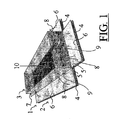
- Figure 1 shows a device in which the method for making spatial forms having more or less sharp edges, to be formed from a mainly plane fibrous sheet material (PFS) 1 (pre-)treated with a binder material, may be performed.
- PFS plane fibrous sheet material
- the PFS 1 preferably will be cut into a form that corresponds with the intended product: in figure 1 .
- the sheet comprises a bottom part (not seen) below the bottom side of an inner mould 3 and side parts 6, which may be pressed up by solid flaps 4 of an outer mould 2. Additional pieces of sheet may optionally be affixed to the vertical edges of the inner mould 3 to achieve a good connection between the adjacent sheet flaps 6 after the deformation process.
- the sheet 1 is to be placed between the inner (solid) mould 3 (which may be hollow as the figure shows) having outer edges 9 and a further outer shape that corresponds to the inner one of the desired spatial form of the PFS, and (solid) pressing means, here in the form of the outer mould 2, with pivotal flaps 4 which may be operated manually or by a mechanical drive.
- the flaps 4 of outer mould 2 are movable (see arrows 8) around pivots 5 (e.g. some kind of "piano hinge") thus achieving that the side parts 6 of PFS 1 are carefully bent or folded under pressure of those flaps 4 around the outer edges of the inner mould 3 without the sheet 1 being bulged or rolled-up.
- the flaps 4 will press the PFS around the inner mould's further outer shape until the desired spatial form has been reached completely.
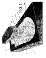
- a method, not part of the invention may be performed using an inner and an outer mould being moved relative to each other perpendicular to the PFS's plane, as illustrated in figure 2.
- Figure 2 shows an outer mould 12, comprising a chamber 14, comprising fixed inner edges 16 and a further inner shape which corresponds to the desired spatial form of the PFS 11.
- the outer mould 12 and an inner mould 13 are moved (see arrows 15) relative to each other perpendicularly to the PFS's plane.
- the inner mould 13 has outer edges 17 and a further outer shape that correspond to the inner ones of the desired spatial form of the PFS.
- the undeformed PFS 11 preferably will be cut in a form that will result, after forming, in the desired spatial form. Due to the occurring shearing of the fibres during forming, the dimensions of the undeformed PFS 11 will have to be matched to the fibre orientations.
- the inner mould 13 then is moved into the hollow chamber 14 of outer mould 12, pressing the sheet 11 between the outer edges (comers) 17 and sides of the inner mould 13 and the edges 16 and 18 and sides of the outer mould's chamber 14 without -due to the dragging and/or stretching forces applied upon the deforming sheet- being bulged or rolled-up.
- the inner shape of the outer mould's chamber 14 will press further the PFS around the inner mould's outer shape until the desired spatial form has been reached completely.
- spatial forms can be made of a PFS in an efficient way, which products excel by their sharp edges and further shapes, having no bulges etc.
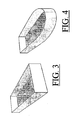
- Self-explaining figure 3 illustrates the product, made according the method and means illustrated in figure 1 . .
- edges 17 and 18 will have to be smooth in some extend, to facilitate the deformation process of the sheet 11, sliding and/or bending around those edges 17 and 18 during the displacement 15 of both moulds 12 and 13 towards another.
Landscapes
- Engineering & Computer Science (AREA)
- Chemical & Material Sciences (AREA)
- Composite Materials (AREA)
- Mechanical Engineering (AREA)
- Textile Engineering (AREA)
- Casting Or Compression Moulding Of Plastics Or The Like (AREA)
- Nonwoven Fabrics (AREA)
- Dry Formation Of Fiberboard And The Like (AREA)
- Processing And Handling Of Plastics And Other Materials For Molding In General (AREA)
Abstract
Description
- The invention refers to a method for making spatial forms having more or less sharp edges, to be formed from mainly plane fibrous material.
- Fibrous material (woven or non-woven, crimp or non-crimp) may be treated with a so-called preforming or binder material. Such a preforming material may e.g. comprise a thermoplastic or partially cured epoxy powder which is applied to the outer surface of the fibrous material (coating) and/or between its fibres (impregnation). Hereinafter this kind of material will be indicated by the acronym PFS, which stands for "Pre-treated Fibrous Sheet (material)".
- According to a known method to manufacture three-dimensional forms made by PFS, one or more PFS layers may be laid in or upon an (inner or outer) mould, vacuum bagged by means of e.g. a cover foil, and heated to typically 120-180°C. Additional pressure to the moulding may be provided by an autoclave (effectively a pressurized oven) which can apply up to 5 atmospheres to the layer(s). After cooling down the resulting rigid form may be take from the mould and put into e.g. an injection mould, serving as a preformed fibre-reinforcement backbone for a synthetic resin component for e.g. aircraft (wings, tail sections etc.), F1 racing cars, sporting goods such as tennis racquets and skis etc.
- Drawbacks of the known method are a long cycle time, difficulties to set-up a flow-directed production and the vacuum bagging step, especially vacuum-tight covering the PFS laying upon the mould surface, which is a specialistic and risk full work. Furthermore, by applying pressure, the in-plane movement of the PFS layers is restricted due to frictional forces. These in-plane movements like interply slip, shearing of fibres or stretching of layers are needed to allow the formation of a three dimensional preform. The restriction of in-plane movement normally leads to geometrical problems like folds and fibre bridging in negative radii. During the subsequent injection step, this will lead to problems with mould-closing or unwanted runner channels for the resin.
- Document
US 6004123 discloses the preamble of claim 1. - The invention is based on the observation that layers of PFS need to be deformed to a desired three dimensional shape prior to the application of a normal pressure which would lead to undesirable frictional forces, restricting the deformation. As a result of those observations two implementations have been developed for manufacturing spatial forms having more or less sharp edges (and/or comers), to be formed from mainly plane PFS, in the following way:
- Place the PFS between an inner mould having outer edges and a further outer shape that correspond to the inner ones (edges and shape respectively) of the desired spatial form of the PFS and solid pressing means;
- Press the PFS around the inner mould's outer edges and subsequently press the PFS around the inner mould's further outer shape. By applying heat, the preform is consolidated.
- As far as the deformation mechanisms can be observed and understood, especially pressing the PFS around the inner mould's outer edges may be coupled with shearing and/or shifting and/or sliding of the constituting fibres and/or fibre layers without, however, damaging those fibres. The same seems to apply at subsequently pressing the PFS around the inner mould's further outer shape.
- As far as can be understood, it is preferred that pressing the PFS around the inner mould's further outer shape should be preceded by pressing the PFS around the inner mould's outer edges, to prevent bulging etc. of the constituting sheet material.
- Preferably, pressing the PFS around the inner mould's outer edges may be performed by means of moving an outer solid mould, or parts of it, towards the inner mould's edges, while, preferably, pressing the PFS around the inner mould's further outer shape may be enabled by continuing the movement of the outer mould or parts thereof relative to the inner mould, until the desired spatial form has been reached.
- The outer mould may comprise pivotal parts which may be moved around said outer edges of the inner mould, having the PFS between them. Use of pivotal parts, pressing ("folding") the PFS towards the inner mould form, appears to fulfill, as far as can be seen and understood, the preferred sequence to press the PFS around the inner mould's outer edges at first, to be followed by pressing the PFS around the inner mould's further outer shape. A restriction of the use of pivotal pressing parts is that only rather straight shapes can be made in that way.
-
-
Figure 1 illustrates the proposed method, using a first option. -
Figure 2 illustrates a second option, not part of the invention. -
Figures 3 and 4 illustrate the respective resulting PFS products. -
Figure 1 shows a device in which the method for making spatial forms having more or less sharp edges, to be formed from a mainly plane fibrous sheet material (PFS) 1 (pre-)treated with a binder material, may be performed. - The PFS 1 preferably will be cut into a form that corresponds with the intended product: in
figure 1 . The sheet comprises a bottom part (not seen) below the bottom side of an inner mould 3 and side parts 6, which may be pressed up by solid flaps 4 of an outer mould 2. Additional pieces of sheet may optionally be affixed to the vertical edges of the inner mould 3 to achieve a good connection between the adjacent sheet flaps 6 after the deformation process. - The sheet 1 is to be placed between the inner (solid) mould 3 (which may be hollow as the figure shows) having
outer edges 9 and a further outer shape that corresponds to the inner one of the desired spatial form of the PFS, and (solid) pressing means, here in the form of the outer mould 2, with pivotal flaps 4 which may be operated manually or by a mechanical drive. Firstly the outer and the inner mould are pressed upon each other, as indicated byarrow 10. The flaps 4 of outer mould 2 are movable (see arrows 8) around pivots 5 (e.g. some kind of "piano hinge") thus achieving that the side parts 6 of PFS 1 are carefully bent or folded under pressure of those flaps 4 around the outer edges of the inner mould 3 without the sheet 1 being bulged or rolled-up. - Continuing the movement 8 of the outer mould's flaps 4, the flaps 4 will press the PFS around the inner mould's further outer shape until the desired spatial form has been reached completely.
- When the spatial form of the product to be made is not fit to use pivotal flaps, e.g. due to a curved part of that form, a method, not part of the invention, may be performed using an inner and an outer mould being moved relative to each other perpendicular to the PFS's plane, as illustrated in
figure 2. Figure 2 shows anouter mould 12, comprising achamber 14, comprising fixedinner edges 16 and a further inner shape which corresponds to the desired spatial form of thePFS 11. Theouter mould 12 and aninner mould 13 are moved (see arrows 15) relative to each other perpendicularly to the PFS's plane. Theinner mould 13 hasouter edges 17 and a further outer shape that correspond to the inner ones of the desired spatial form of the PFS. Theundeformed PFS 11 preferably will be cut in a form that will result, after forming, in the desired spatial form. Due to the occurring shearing of the fibres during forming, the dimensions of theundeformed PFS 11 will have to be matched to the fibre orientations. After that the PFS 11 is put between theinner mould 13 and theouter mould 12. Theinner mould 13 then is moved into thehollow chamber 14 ofouter mould 12, pressing thesheet 11 between the outer edges (comers) 17 and sides of theinner mould 13 and theedges chamber 14 without -due to the dragging and/or stretching forces applied upon the deforming sheet- being bulged or rolled-up. Continuing themovement 15 of the inner and outer moulds towards another the inner shape of the outer mould'schamber 14 will press further the PFS around the inner mould's outer shape until the desired spatial form has been reached completely. - Performing the method by the means as illustrated in
figure 1 , spatial forms can be made of a PFS in an efficient way, which products excel by their sharp edges and further shapes, having no bulges etc. - Self-explaining
figure 3 illustrates the product, made according the method and means illustrated infigure 1 . . - Finally, it is noted that, of course, the
edges sheet 11, sliding and/or bending around thoseedges displacement 15 of bothmoulds
Claims (2)
- Method for making preforms having sharp edges, to be formed from a mainly plane fibrous material including fibre layers, treated with a preforming or binder material, hereinafter called a PFS, the method comprising the steps of:- placing the PFS (1) between an inner mould (3) having outer edges (9) and a further outer shape that corresponds to the inner ones of the desired spatial form of the PFS and solid pressing means (4); characterized by- pressing the PFS around the inner mould's outer edges while allowing fibre layers to slide;- subsequently pressing the PFS around the inner mould's further outer shape, and consolidating the preform by applying heat,
wherein said pressing the PFS around the inner mould's outer edges is performed by moving (8,10) an outer mould (1) or parts (4) thereof towards the inner mould's edges (9) and wherein pressing the PFS around the inner mould's further outer shape is performed by moving (8,10) the outer mould (1) or parts thereof (4) relative to the inner mould until the desired spatial form has been reached. - Method according to claim 1, the outer mould comprising pivotal parts (4) which are moved around said outer edges of the inner mould, having the PFS between them.
Priority Applications (4)
| Application Number | Priority Date | Filing Date | Title |
|---|---|---|---|
| AT04075260T ATE469754T1 (en) | 2004-01-28 | 2004-01-28 | METHOD FOR PRODUCING PREFORMS FROM FIBER LAYER MATERIAL |
| DE602004027460T DE602004027460D1 (en) | 2004-01-28 | 2004-01-28 | Process for the production of preforms from fibrous layer material |
| PT04075260T PT1559533E (en) | 2004-01-28 | 2004-01-28 | Method for making preforms of fibrous sheet material |
| EP04075260A EP1559533B1 (en) | 2004-01-28 | 2004-01-28 | Method for making preforms of fibrous sheet material |
Applications Claiming Priority (1)
| Application Number | Priority Date | Filing Date | Title |
|---|---|---|---|
| EP04075260A EP1559533B1 (en) | 2004-01-28 | 2004-01-28 | Method for making preforms of fibrous sheet material |
Publications (2)
| Publication Number | Publication Date |
|---|---|
| EP1559533A1 EP1559533A1 (en) | 2005-08-03 |
| EP1559533B1 true EP1559533B1 (en) | 2010-06-02 |
Family
ID=34639448
Family Applications (1)
| Application Number | Title | Priority Date | Filing Date |
|---|---|---|---|
| EP04075260A Expired - Lifetime EP1559533B1 (en) | 2004-01-28 | 2004-01-28 | Method for making preforms of fibrous sheet material |
Country Status (4)
| Country | Link |
|---|---|
| EP (1) | EP1559533B1 (en) |
| AT (1) | ATE469754T1 (en) |
| DE (1) | DE602004027460D1 (en) |
| PT (1) | PT1559533E (en) |
Families Citing this family (2)
| Publication number | Priority date | Publication date | Assignee | Title |
|---|---|---|---|---|
| FR2944730B1 (en) * | 2009-04-24 | 2012-09-28 | Daher Aerospace | STAMPING TOOL FOR THERMOPLASTIC PARTS AND METHOD. |
| DE102012202620B4 (en) * | 2011-11-17 | 2015-02-26 | Johnson Controls Gmbh | Method for producing a structural component, device for carrying out the method |
Citations (2)
| Publication number | Priority date | Publication date | Assignee | Title |
|---|---|---|---|---|
| CA1013527A (en) * | 1970-03-25 | 1977-07-12 | Anthony M. Fazzari | Glass reinforced composites with improved surface and process |
| US6004123A (en) * | 1989-12-06 | 1999-12-21 | C.A. Lawton Company | Apparatus for making preforms |
Family Cites Families (3)
| Publication number | Priority date | Publication date | Assignee | Title |
|---|---|---|---|---|
| SE459204B (en) * | 1986-01-27 | 1989-06-12 | Laxao Bruks Ab | SEAT AND DEVICE FOR MANUFACTURING THE FORM PIECE OF BINDING IMPRESSED MINERAL WOOL |
| US6245275B1 (en) * | 1999-05-13 | 2001-06-12 | Vought Aircraft Industries, Inc. | Method for fabricating composite structures |
| FR2806349B1 (en) * | 2000-03-20 | 2002-12-06 | Plastic Omnium Cie | PROCESS FOR MANUFACTURING A REINFORCED PLASTIC PART |
-
2004
- 2004-01-28 EP EP04075260A patent/EP1559533B1/en not_active Expired - Lifetime
- 2004-01-28 DE DE602004027460T patent/DE602004027460D1/en not_active Expired - Lifetime
- 2004-01-28 AT AT04075260T patent/ATE469754T1/en not_active IP Right Cessation
- 2004-01-28 PT PT04075260T patent/PT1559533E/en unknown
Patent Citations (2)
| Publication number | Priority date | Publication date | Assignee | Title |
|---|---|---|---|---|
| CA1013527A (en) * | 1970-03-25 | 1977-07-12 | Anthony M. Fazzari | Glass reinforced composites with improved surface and process |
| US6004123A (en) * | 1989-12-06 | 1999-12-21 | C.A. Lawton Company | Apparatus for making preforms |
Also Published As
| Publication number | Publication date |
|---|---|
| PT1559533E (en) | 2010-08-05 |
| EP1559533A1 (en) | 2005-08-03 |
| ATE469754T1 (en) | 2010-06-15 |
| DE602004027460D1 (en) | 2010-07-15 |
Similar Documents
| Publication | Publication Date | Title |
|---|---|---|
| KR102102667B1 (en) | Method and apparatus for forming thick thermoplastic composite structures | |
| CA2790614C (en) | Continuous molding of thermoplastic laminates | |
| US5843355A (en) | Method for molding a thermoplastic composite sine wave spar structure | |
| US8585952B2 (en) | Pressure molded preform process for composite structures | |
| EP2605900B1 (en) | Process for shaping a flat working material into a composite product | |
| EP1773587B1 (en) | Recyclable composite plastic and related manufacturing methods | |
| US20160332392A1 (en) | Method of forming composite structures | |
| WO2013178755A1 (en) | Press moulding method | |
| JP2015536260A5 (en) | ||
| CA2860726A1 (en) | A method and device for producing a three-dimensional preform from a laid scrim in the course of production of fibre-reinforced moulded parts | |
| EP2186627A2 (en) | Method for continuously forming composite material shape member having varied cross-sectional shape | |
| EP1559533B1 (en) | Method for making preforms of fibrous sheet material | |
| EP4096906B1 (en) | Thermoplastic composite having one or more inner openings and method for moulding said composite | |
| CA2741171A1 (en) | Hot drape forming by means of a stiffness controlled vacuum bag | |
| EP1237696A1 (en) | Method for the manufacture of a composite product and press mould for carrying out the method |
Legal Events
| Date | Code | Title | Description |
|---|---|---|---|
| PUAI | Public reference made under article 153(3) epc to a published international application that has entered the european phase |
Free format text: ORIGINAL CODE: 0009012 |
|
| AK | Designated contracting states |
Kind code of ref document: A1 Designated state(s): AT BE BG CH CY CZ DE DK EE ES FI FR GB GR HU IE IT LI LU MC NL PT RO SE SI SK TR |
|
| AX | Request for extension of the european patent |
Extension state: AL LT LV MK |
|
| AKX | Designation fees paid | ||
| 17P | Request for examination filed |
Effective date: 20060407 |
|
| RBV | Designated contracting states (corrected) |
Designated state(s): AT BE BG CH CY CZ DE DK EE ES FI FR GB GR HU IE IT LI LU MC NL PT RO SE SI SK TR |
|
| REG | Reference to a national code |
Ref country code: DE Ref legal event code: 8566 |
|
| RAP1 | Party data changed (applicant data changed or rights of an application transferred) |
Owner name: TNO BEDRIJVEN B.V. |
|
| 17Q | First examination report despatched |
Effective date: 20071016 |
|
| RAP1 | Party data changed (applicant data changed or rights of an application transferred) |
Owner name: LIGHTWEIGHT STRUCTURES B.V. |
|
| GRAP | Despatch of communication of intention to grant a patent |
Free format text: ORIGINAL CODE: EPIDOSNIGR1 |
|
| RTI1 | Title (correction) |
Free format text: METHOD FOR MAKING PREFORMS OF FIBROUS SHEET MATERIAL |
|
| GRAS | Grant fee paid |
Free format text: ORIGINAL CODE: EPIDOSNIGR3 |
|
| GRAA | (expected) grant |
Free format text: ORIGINAL CODE: 0009210 |
|
| AK | Designated contracting states |
Kind code of ref document: B1 Designated state(s): AT BE BG CH CY CZ DE DK EE ES FI FR GB GR HU IE IT LI LU MC NL PT RO SE SI SK TR |
|
| REG | Reference to a national code |
Ref country code: GB Ref legal event code: FG4D |
|
| REG | Reference to a national code |
Ref country code: CH Ref legal event code: EP |
|
| REG | Reference to a national code |
Ref country code: IE Ref legal event code: FG4D |
|
| REF | Corresponds to: |
Ref document number: 602004027460 Country of ref document: DE Date of ref document: 20100715 Kind code of ref document: P |
|
| REG | Reference to a national code |
Ref country code: PT Ref legal event code: SC4A Free format text: AVAILABILITY OF NATIONAL TRANSLATION Effective date: 20100729 |
|
| REG | Reference to a national code |
Ref country code: NL Ref legal event code: T3 |
|
| PG25 | Lapsed in a contracting state [announced via postgrant information from national office to epo] |
Ref country code: SE Free format text: LAPSE BECAUSE OF FAILURE TO SUBMIT A TRANSLATION OF THE DESCRIPTION OR TO PAY THE FEE WITHIN THE PRESCRIBED TIME-LIMIT Effective date: 20100602 |
|
| PG25 | Lapsed in a contracting state [announced via postgrant information from national office to epo] |
Ref country code: FI Free format text: LAPSE BECAUSE OF FAILURE TO SUBMIT A TRANSLATION OF THE DESCRIPTION OR TO PAY THE FEE WITHIN THE PRESCRIBED TIME-LIMIT Effective date: 20100602 Ref country code: AT Free format text: LAPSE BECAUSE OF FAILURE TO SUBMIT A TRANSLATION OF THE DESCRIPTION OR TO PAY THE FEE WITHIN THE PRESCRIBED TIME-LIMIT Effective date: 20100602 Ref country code: SI Free format text: LAPSE BECAUSE OF FAILURE TO SUBMIT A TRANSLATION OF THE DESCRIPTION OR TO PAY THE FEE WITHIN THE PRESCRIBED TIME-LIMIT Effective date: 20100602 |
|
| PG25 | Lapsed in a contracting state [announced via postgrant information from national office to epo] |
Ref country code: GR Free format text: LAPSE BECAUSE OF FAILURE TO SUBMIT A TRANSLATION OF THE DESCRIPTION OR TO PAY THE FEE WITHIN THE PRESCRIBED TIME-LIMIT Effective date: 20100903 Ref country code: CY Free format text: LAPSE BECAUSE OF FAILURE TO SUBMIT A TRANSLATION OF THE DESCRIPTION OR TO PAY THE FEE WITHIN THE PRESCRIBED TIME-LIMIT Effective date: 20100602 |
|
| PG25 | Lapsed in a contracting state [announced via postgrant information from national office to epo] |
Ref country code: EE Free format text: LAPSE BECAUSE OF FAILURE TO SUBMIT A TRANSLATION OF THE DESCRIPTION OR TO PAY THE FEE WITHIN THE PRESCRIBED TIME-LIMIT Effective date: 20100602 |
|
| PG25 | Lapsed in a contracting state [announced via postgrant information from national office to epo] |
Ref country code: RO Free format text: LAPSE BECAUSE OF FAILURE TO SUBMIT A TRANSLATION OF THE DESCRIPTION OR TO PAY THE FEE WITHIN THE PRESCRIBED TIME-LIMIT Effective date: 20100602 Ref country code: SK Free format text: LAPSE BECAUSE OF FAILURE TO SUBMIT A TRANSLATION OF THE DESCRIPTION OR TO PAY THE FEE WITHIN THE PRESCRIBED TIME-LIMIT Effective date: 20100602 Ref country code: CZ Free format text: LAPSE BECAUSE OF FAILURE TO SUBMIT A TRANSLATION OF THE DESCRIPTION OR TO PAY THE FEE WITHIN THE PRESCRIBED TIME-LIMIT Effective date: 20100602 |
|
| PG25 | Lapsed in a contracting state [announced via postgrant information from national office to epo] |
Ref country code: IT Free format text: LAPSE BECAUSE OF FAILURE TO SUBMIT A TRANSLATION OF THE DESCRIPTION OR TO PAY THE FEE WITHIN THE PRESCRIBED TIME-LIMIT Effective date: 20100602 |
|
| PLBE | No opposition filed within time limit |
Free format text: ORIGINAL CODE: 0009261 |
|
| STAA | Information on the status of an ep patent application or granted ep patent |
Free format text: STATUS: NO OPPOSITION FILED WITHIN TIME LIMIT |
|
| PG25 | Lapsed in a contracting state [announced via postgrant information from national office to epo] |
Ref country code: DK Free format text: LAPSE BECAUSE OF FAILURE TO SUBMIT A TRANSLATION OF THE DESCRIPTION OR TO PAY THE FEE WITHIN THE PRESCRIBED TIME-LIMIT Effective date: 20100602 |
|
| 26N | No opposition filed |
Effective date: 20110303 |
|
| REG | Reference to a national code |
Ref country code: DE Ref legal event code: R097 Ref document number: 602004027460 Country of ref document: DE Effective date: 20110302 |
|
| PG25 | Lapsed in a contracting state [announced via postgrant information from national office to epo] |
Ref country code: MC Free format text: LAPSE BECAUSE OF NON-PAYMENT OF DUE FEES Effective date: 20110131 |
|
| REG | Reference to a national code |
Ref country code: CH Ref legal event code: PL |
|
| REG | Reference to a national code |
Ref country code: FR Ref legal event code: ST Effective date: 20110930 |
|
| REG | Reference to a national code |
Ref country code: IE Ref legal event code: MM4A |
|
| PG25 | Lapsed in a contracting state [announced via postgrant information from national office to epo] |
Ref country code: FR Free format text: LAPSE BECAUSE OF NON-PAYMENT OF DUE FEES Effective date: 20110131 Ref country code: CH Free format text: LAPSE BECAUSE OF NON-PAYMENT OF DUE FEES Effective date: 20110131 Ref country code: LI Free format text: LAPSE BECAUSE OF NON-PAYMENT OF DUE FEES Effective date: 20110131 |
|
| REG | Reference to a national code |
Ref country code: PT Ref legal event code: MM4A Free format text: LAPSE DUE TO NON-PAYMENT OF FEES Effective date: 20111028 |
|
| REG | Reference to a national code |
Ref country code: DE Ref legal event code: R119 Ref document number: 602004027460 Country of ref document: DE Effective date: 20110802 |
|
| PG25 | Lapsed in a contracting state [announced via postgrant information from national office to epo] |
Ref country code: IE Free format text: LAPSE BECAUSE OF NON-PAYMENT OF DUE FEES Effective date: 20110128 Ref country code: PT Free format text: LAPSE BECAUSE OF NON-PAYMENT OF DUE FEES Effective date: 20111028 |
|
| PG25 | Lapsed in a contracting state [announced via postgrant information from national office to epo] |
Ref country code: LU Free format text: LAPSE BECAUSE OF NON-PAYMENT OF DUE FEES Effective date: 20110128 |
|
| PG25 | Lapsed in a contracting state [announced via postgrant information from national office to epo] |
Ref country code: DE Free format text: LAPSE BECAUSE OF NON-PAYMENT OF DUE FEES Effective date: 20110802 |
|
| PG25 | Lapsed in a contracting state [announced via postgrant information from national office to epo] |
Ref country code: BG Free format text: LAPSE BECAUSE OF FAILURE TO SUBMIT A TRANSLATION OF THE DESCRIPTION OR TO PAY THE FEE WITHIN THE PRESCRIBED TIME-LIMIT Effective date: 20100902 Ref country code: TR Free format text: LAPSE BECAUSE OF FAILURE TO SUBMIT A TRANSLATION OF THE DESCRIPTION OR TO PAY THE FEE WITHIN THE PRESCRIBED TIME-LIMIT Effective date: 20100602 |
|
| PG25 | Lapsed in a contracting state [announced via postgrant information from national office to epo] |
Ref country code: ES Free format text: LAPSE BECAUSE OF FAILURE TO SUBMIT A TRANSLATION OF THE DESCRIPTION OR TO PAY THE FEE WITHIN THE PRESCRIBED TIME-LIMIT Effective date: 20100913 Ref country code: HU Free format text: LAPSE BECAUSE OF FAILURE TO SUBMIT A TRANSLATION OF THE DESCRIPTION OR TO PAY THE FEE WITHIN THE PRESCRIBED TIME-LIMIT Effective date: 20100602 |
|
| PGFP | Annual fee paid to national office [announced via postgrant information from national office to epo] |
Ref country code: BE Payment date: 20140130 Year of fee payment: 11 |
|
| PGFP | Annual fee paid to national office [announced via postgrant information from national office to epo] |
Ref country code: GB Payment date: 20140130 Year of fee payment: 11 |
|
| PGFP | Annual fee paid to national office [announced via postgrant information from national office to epo] |
Ref country code: NL Payment date: 20141218 Year of fee payment: 12 |
|
| PG25 | Lapsed in a contracting state [announced via postgrant information from national office to epo] |
Ref country code: BE Free format text: LAPSE BECAUSE OF NON-PAYMENT OF DUE FEES Effective date: 20150131 |
|
| GBPC | Gb: european patent ceased through non-payment of renewal fee |
Effective date: 20150128 |
|
| PG25 | Lapsed in a contracting state [announced via postgrant information from national office to epo] |
Ref country code: GB Free format text: LAPSE BECAUSE OF NON-PAYMENT OF DUE FEES Effective date: 20150128 |
|
| REG | Reference to a national code |
Ref country code: NL Ref legal event code: MM Effective date: 20160201 |
|
| PG25 | Lapsed in a contracting state [announced via postgrant information from national office to epo] |
Ref country code: NL Free format text: LAPSE BECAUSE OF NON-PAYMENT OF DUE FEES Effective date: 20160201 |