EP2850940A2 - Garnklemmvorrichtung für eine Ballenpresse - Google Patents
Garnklemmvorrichtung für eine Ballenpresse Download PDFInfo
- Publication number
- EP2850940A2 EP2850940A2 EP14176443.1A EP14176443A EP2850940A2 EP 2850940 A2 EP2850940 A2 EP 2850940A2 EP 14176443 A EP14176443 A EP 14176443A EP 2850940 A2 EP2850940 A2 EP 2850940A2
- Authority
- EP
- European Patent Office
- Prior art keywords
- clamping
- yarn
- recesses
- clamping device
- projections
- Prior art date
- Legal status (The legal status is an assumption and is not a legal conclusion. Google has not performed a legal analysis and makes no representation as to the accuracy of the status listed.)
- Granted
Links
Images
Classifications
-
- A—HUMAN NECESSITIES
- A01—AGRICULTURE; FORESTRY; ANIMAL HUSBANDRY; HUNTING; TRAPPING; FISHING
- A01D—HARVESTING; MOWING
- A01D39/00—Independent binders, e.g. for hay; Binders attachable to mowers
-
- A—HUMAN NECESSITIES
- A01—AGRICULTURE; FORESTRY; ANIMAL HUSBANDRY; HUNTING; TRAPPING; FISHING
- A01F—PROCESSING OF HARVESTED PRODUCE; HAY OR STRAW PRESSES; DEVICES FOR STORING AGRICULTURAL OR HORTICULTURAL PRODUCE
- A01F15/00—Baling presses for straw, hay or the like
- A01F15/08—Details
- A01F15/14—Tying devices specially adapted for baling presses
- A01F15/145—Twine knotters
Definitions
- the present invention relates to a yarn clamping device for use in a baling press.
- a Garnklemmvoroplasty is eg off DE 1 923 729 U1 known.
- Square balers traditionally have a press channel in which a plunger is moved back and forth while pressed crop transversely to its direction in the press channel pressed against an existing bale and thereby compacted. As soon as the crop bale produced in this way has reached its intended size, it is knotted. Binding yarn strands required for this are already wrapped around the bale during the formation of the bale and are subjected to its pressure at each stroke of the bale. A yarn clamping device must exert a sizeable clamping force on the free end of such a twine strand during bale formation to prevent the yarn from escaping from the pinch of the strokes of the piston.
- the object of the invention is therefore to provide a Garnklemmvorraum, in which both the risk of too loose and too tight clamping is reduced.
- the object is achieved by having in a Garnklemmvoriques for a baler with a rotatable around a shaft pinch wheel and a clamping plate, which together define a nip, the nip more along one of the nip extending through the nip and having separated by recesses bottlenecks.
- the twine is exposed to relatively high pressure and accordingly deformed more in cross-section than in the recesses between the bottlenecks. Slippage of the yarn under a tensile force exerted by the plunger therefore requires not only an overcoming of the friction between the yarn and the clamping surfaces of the yarn clamping device, but also a deformation of the yarn clamping device Yarn cross section when passing through a bottleneck.
- the recesses are distributed on the clamping plate and the pinch wheel, but they could also be provided only on the clamping plate or only on the pinch wheel.
- the clamping points are preferably formed by projections and recesses of the clamping plate and clamping wheel, wherein in each case a projection of the clamping plate is a recess of the clamping wheel and / or a recess of the clamping plate is a projection of the clamping wheel opposite.
- a projection of the clamping plate is a recess of the clamping wheel and / or a recess of the clamping plate is a projection of the clamping wheel opposite.
- the projections have flat vertex surfaces.
- the mutually offset projections of clamping wheel and clamping disc exert no cutting action on the yarn
- the expansion of the apex surfaces should expediently each be at least as large as the opposite recesses. Penetration of the apex surfaces into the recess, by which a cutting action could be exerted on the yarn, can be avoided in this way.
- the projections and recesses are linear.
- the line-shaped projections and recesses are preferably oriented perpendicular to a tensile force, held in the clamping device strand of the twine.
- the pinch wheel may have two identical arrangements of projections and recesses which are alternatively positionable with respect to the projections and recesses of the pinch plate and which preferably alternate from one ball to the next when the yarn is clamped.
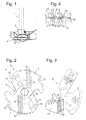
- Fig. 1 shows a side view of a Garnklemmvoroplasty invention without a binding thread strand clamped therein.
- a Garnklemmrad 2 is mounted in a conventional manner.
- a clamping plate 3 is acted upon by a spring, not shown in the figure, against a clamping surface of the yarn clamping wheel 2 facing away from the shaft 1. Since no twine between Garnklemmrad 2 and clamping plate 3 is clamped in the illustrated configuration, a nip 4 is closed between the two, and Garnklemmrad 2 and clamping plate 3 touch each other in places.
- Fig. 2 shows a plan view of the clamping plate 3 facing side of the Garnklemmrades 2.
- a flat clamping surface 5 of the Garnklemmrades 2 is dumbbell-shaped in plan view, with a central piece 6, on which the shaft 1 is anchored rotationally fixed, and two compared to the middle piece 6 widened End pieces 7.
- End pieces 7 In each of these end pieces 7, an array of a plurality of parallel, wave-shaped recesses 8 is formed. Projections 9 between the recesses 8 lie in a plane with the surrounding clamping surface 5.
- the end pieces 7 each have, against the recesses 8 in a clockwise direction offset, an edge notch 10 and, offset in the counterclockwise direction, from the plane of the clamping surface 5 obliquely rising edge 11, in which a slot 12 is formed.
- a tie yarn needle not shown here, guides a twine strand to one of the end pieces 7 so that it is looped over the clamping surface 5 between edge notch 10 and flank 11 and thereby the recesses 8 crosses.
- the slot 12 is moved over a stationary knife away, so that the knife severed the twine strand. Of the two yarn ends thus obtained, one hangs from the already knotted bale and leaves the knotter; the other remains clamped in the clamping device.
- a free end of the twine strand is approximately level with one of the two flanks 11 of pinch wheel 2, and the twine string extends substantially perpendicularly across one of the groups of slots 8 to the edge notch 10.
- the twine strand which is deflected at the edge notch 10, continues to extend in the direction of the press channel, where it is exposed to the tensile force of the piston compressing the crop.
- the Garnklemmrad 2 is located in Fig. 3 opposite clamping plate 3 shown in plan view. Also, it has a substantially flat clamping surface 13, in a group of rectilinear recess 14 is formed.
- the recesses 14 are more numerous than the recesses 8 of the pinch wheel 2.
- These recesses 14 and protrusions 15 extending therebetween and engaging with the clamping surface 13 cooperate with one of the groups of recesses 8 and projections 9 of the yarn clamping wheel 2 to clamp the twine strand at its cut end.
- Fig. 4 shows a cross section through Garnklemmrad 2 and clamping plate 3 along the clamped, here denoted by 16 twine strand.
- the clamping surface 13 of the clamping plate 3 takes only the left part of Fig. 4 one; it ends at an oblique shoulder 17, beyond which the distance between Garnklemmrad 2 and clamping plate 3 is too large to clamp the twine strand 16 and deform.
- the twine strand 16 is therefore flattened only to the left of the shoulder 17; to the right of her, he can be seen with his natural diameter of about 5 mm.
- the projections 9, 15 each have planar, the recesses 8, 14 facing end faces, which here are each slightly wider than the opposite recesses 8, 14. This ensures that the twine strand 16 at those bottlenecks 18, where in each case edges are opposed to the projections 9 and 15, although deformed in cross-section, but is exposed to substantially no shear stress, which could lead to damage and ultimately tearing of the strand 16 under the tensile force exerted by the plunger.
- twine strand 16 can therefore only give in to the train of the plunger and slip in the nip 4, if at each constriction 18 not only the frictional resistance but also the resistance of the twine strand 16 is overcome against deformation of its cross section. Since the projections 9, 15 are slightly wider than the opposite recesses 14, 8, they can not engage in the recesses and consequently exert no tensile stress on the twine strand 16, which add to the tensile stress of the piston and thereby the tearing of the strand 16th would favor. Thus, a tight fit of the twine strand is achieved with a relatively low material stress, so that both the risk of tearing and the escape from the nip 4 are reduced.
Landscapes
- Life Sciences & Earth Sciences (AREA)
- Environmental Sciences (AREA)
- Basic Packing Technique (AREA)
- Spinning Or Twisting Of Yarns (AREA)
Abstract
Description
- Die vorliegende Erfindung betrifft eine Garnklemmvorrichtung zum Einsatz in einer Ballenpresse. Eine solche Garnklemmvorrichtung ist z.B. aus
DE 1 923 729 U1 bekannt. - Quaderballenpressen haben herkömmlicherweise einen Presskanal, in dem ein Presskolben hin und her bewegt wird und dabei quer zu seiner Bewegungsrichtung in den Presskanal eingeführtes Erntegut gegen einen bereits vorhandenen Ballen andrückt und dabei verdichtet. Sobald der auf diese Weise entstehende Erntegutballen vorgesehene Größe erreicht hat, wird er verknotet. Hierfür benötigte Bindegarnstränge sind bereits während der Entstehung des Ballens um diesen herumgeschlungen und sind bei jedem Hub des Kolbens dessen Druck ausgesetzt. Eine Garnklemmvorrichtung, muss während der Ballenbildung eine berträchtliche Klemmkraft auf das freie Ende eines solchen Bindegarnstrangs ausüben, damit das Garn von den Hüben des Kolbens nicht aus der Klemmung entweicht. Wenn jedoch bei einer herkömmlichen Garnklemmvorrichtung die Klemmkraft, der das Bindegarn zwischen Klemmrad und Klemmplatte ausgesetzt ist, zu hoch gewählt ist, dann besteht die Gefahr, dass das Garn durch die Klemmung innerlich Schaden nimmt und schließlich unter dem Druck des Kolbens reißt. Wenn zu locker geklemmtes Garn aus der Klemmvorrichtung entweicht oder zu fest geklemmtes Garn reißt, sind die Folgen für den Betrieb der Ballenpresse ähnlich. Der Ballen kann nicht mehr fertig gestellt werden, das Material des unfertigen Ballens muss aus dem Presskanal beseitigt werden, und das Bindegarn muss neu in die Klemmvorrichtung eingeführt und in dieser befestigt werden. Die damit verbundenen Arbeitsunterbrechungen beeinträchtigen erheblich die Wirtschaftlichkeit eines Erntevorgangs.
- Aufgabe der Erfindung ist daher, eine Garnklemmvorrichtung zu schaffen, bei der sowohl die Gefahr einer zu lockeren als auch einer zu festen Klemmung verringert ist.
- Die Aufgabe wird gelöst, indem bei einer Garnklemmvorrichtung für eine Ballenpresse mit einem um eine Welle drehbaren Klemmrad und einer Klemmplatte, die gemeinsam einen Klemmspalt begrenzen, der Klemmspalt mehrere entlang eines die sich durch den Klemmspalt erstreckenden Bindegarnstrangs verteilte und durch Aussparungen voneinander getrennte Engstellen aufweist. An den Engstellen ist das Bindegarn relativ starkem Druck ausgesetzt und dementsprechend stärker im Querschnitt verformt als in den Aussparungen zwischen den Engstellen. Ein Verrutschen des Garns unter einer vom Presskolben ausgeübten Zugkraft erfordert daher nicht nur eine Überwindung der Reibung zwischen dem Garn und dem es klemmenden Oberflächen der Garnklemmvorrichtung, sondern gleichzeitig auch eine Verformung des Garnquerschnitts beim Durchtritt durch eine Engstelle. Um eine gegebene Zugbelastbarkeit der Klemmen zu erreichen, ist daher weniger Reibungswiderstand erforderlich, als wenn das Garn in einem Klemmspalt mit konstanter oder sich zum Knoter hin vergrößernder Spaltbreite geklemmt ist. Dies erlaubt es, die Klemmkraft (und damit die Gefahr einer Beschädigung des Garns durch die Klemmung) zu verringern, ohne dass gleichzeitig die Zugbelastbarkeit der Klemmung abnimmt.
- Vorzugsweise sind die Aussparungen auf die Klemmplatte und das Klemmrad verteilt, sie könnten allerdings auch nur an der Klemmplatte oder nur am Klemmrad vorgesehen sein.
- Die Klemmstellen sind vorzugsweise durch Vorsprünge und Aussparungen von Klemmplatte und Klemmrad gebildet, wobei jeweils einem Vorsprung der Klemmplatte eine Aussparung des Klemmrades und/oder einer Aussparung der Klemmplatte ein Vorsprung des Klemmrades gegenüber liegt. Auf diese Weise wird das Garn nicht nur an den Engstellen im Querschnitt verformt, sondern es wird auch auf engem Radius gekrümmt, so dass zum Herausziehen des Garnes aus der Klemmung zusätzlich auch noch Walkarbeit zu leisten ist. Auch dies trägt zum Widerstand des Garnes gegen das Herausziehen aus dem Klemmspalt bei.
- Vorzugsweise haben die Vorsprünge ebene Scheitelflächen. Damit die gegeneinander versetzten Vorsprünge von Klemmrad und Klemmscheibe keine Schneidwirkung auf das Garn ausüben, sollte die Ausdehnung der Scheitelflächen zweckmäßigerweise jeweils wenigstens so groß sein wie der ihnen gegenüberliegenden Aussparungen. Ein Eindringen der Scheitelflächen in die Aussparung, durch das auf das Garn eine Schneidwirkung ausgeübt werden könnte, kann auf diese Weise vermieden werden.
- Vorzugsweise sind die Vorsprünge und Aussparungen linienförmig.
- Damit das im Klemmspalt geklemmte Garn einer Zugbelastung durch den Presskolben nicht durch eine Bewegung quer zur Kraftrichtung ausweichen kann, sind die linienförmigen Vorsprünge und Aussparungen vorzugsweise senkrecht zu einem der Zugkraft ausgesetzten, in der Klemmvorrichtung gehaltenen Strang des Bindegarns orientiert.
- Das Klemmrad kann zwei identische Anordnungen von Vorsprüngen und Aussparungen aufweisen, die alternativ gegenüber den Vorsprüngen und Aussparungen der Klemmplatte positionierbar sind und die sich beim Klemmen des Garns vorzugsweise von einem Ballen zum nächsten abwechseln.
- Weitere Merkmale und Vorteile der Erfindung ergeben sich aus der nachfolgenden Beschreibung von Ausführungsbeispielen unter Bezugnahme auf die beigefügten Figuren. Es zeigen:
- Fig. 1
- eine Seitenansicht der Garnklemmvorrichtung;
- Fig. 2
- eine Draufsicht auf die Klemmfläche eines Klemmrades der Garnklemmvorrichtung;
- Fig. 3
- eine Draufsicht auf die Klemmfläche einer Klemmplatte der Garnklemmvorrichtung; und
- Fig. 4
- einen Schnitt durch Klemmplatte und Klemmrad entlang eines zwischen ihnen geklemmten Bindegarnstrangs.
-
Fig. 1 zeigt eine Seitenansicht einer erfindungsgemäßen Garnklemmvorrichtung ohne einen darin geklemmten Bindegarnstrang. An der Spitze einer periodisch drehangetriebenen Welle 1 ist in an sich bekannter Weise ein Garnklemmrad 2 montiert. Eine Klemmplatte 3 ist von einer in der Fig. nicht dargestellten Feder gegen eine von der Welle 1 abgewandte Klemmfläche des Garnklemmrades 2 beaufschlagt. Da in der dargestellten Konfiguration kein Bindegarn zwischen Garnklemmrad 2 und Klemmplatte 3 eingeklemmt ist, ist ein Klemmspalt 4 zwischen beiden geschlossen, und Garnklemmrad 2 und Klemmplatte 3 berühren einander stellenweise. -
Fig. 2 zeigt eine Draufsicht auf die der Klemmplatte 3 zugewandte Seite des Garnklemmrades 2. Eine ebene Klemmfläche 5 des Garnklemmrades 2 ist in der Draufsicht hantelähnlich geformt, mit einem Mittelstück 6, an dem die Welle 1 drehfest verankert ist, und zwei im Vergleich zum Mittelstück 6 verbreiterten Endstücken 7. In jedem dieser Endstücke 7 ist eine Anordnung von mehreren parallelen, wellenförmigen Aussparungen 8 gebildet. Vorsprünge 9 zwischen den Aussparungen 8 liegen in einer Ebene mit der umgebenden Klemmfläche 5. Die Endstücke 7 weisen jeweils, gegen die Aussparungen 8 im Uhrzeigersinn versetzt, eine Randkerbe 10 und, in gegen Uhrzeigersinn versetzt, eine aus der Ebene der Klemmfläche 5 schräg aufsteigende Flanke 11 auf, in der ein Schlitz 12 gebildet ist. Jedes mal, wenn das Sammeln und Verdichten von Material für einen Ballen abgeschlossen ist, führt eine an sich bekannte, hier nicht dargestellte Bindegarnnadel einen Bindegarnstrang an eines der Endstücke 7 heran, so dass es zwischen Randkerbe 10 und Flanke 11 über die Klemmfläche 5 geschlungen wird und dabei die Aussparungen 8 kreuzt. Bei einer anschließenden Drehung des Garnklemmrades 2 um 180° wird der Schlitz 12 über ein ortsfestes Messer hinweg bewegt, so dass das Messer den Bindegarnstrang durchtrennt. Von den dadurch erhaltenen zwei Garnenden hängt eines an dem mittlerweile fertig verknoteten Ballen und verlässt den Knoter; das andere bleibt in der Klemmvorrichtung geklemmt. - Während der darauffolgenden Phase des Verdichtens von Material für den nächsten Ballen befindet sich somit ein freies Ende des Bindegarnstrangs in etwa in Höhe einer der beiden Flanken 11 des Klemmrades 2, und der Bindegarnstrang erstreckt sich über eine der Gruppen von Aussparungen 8 im Wesentlichen rechtwinklig hinweg bis zur Randkerbe 10. Der an der Randkerbe 10 umgelenkte Bindgarnstrang erstreckt sich weiter Richtung des Presskanals, wo er der Zugkraft des das Erntegut verdichtenden Kolbens ausgesetzt ist.
- Dem Garnklemmrad 2 liegt die in
Fig. 3 in Draufsicht gezeigte Klemmplatte 3 gegenüber. Auch sie hat eine im Wesentlichen ebene Klemmfläche 13, in der eine Gruppe von geradlinigen Aussparung 14 gebildet ist. Die Aussparungen 14 sind um eine zahlreicher als die Aussparungen 8 des Klemmrades 2. Im zusammengefügten Zustand derFig. 1 wirken diese Aussparungen 14 und sich zwischen ihnen erstreckende, mit der Klemmfläche 13 bündige Vorsprünge 15 mit einer der Gruppen von Aussparungen 8 und Vorsprüngen 9 des Garnklemmrades 2 zusammen, um den Bindegarnstrang an seinem abgeschnittenen Ende zu klemmen. -
Fig. 4 zeigt einen Querschnitt durch Garnklemmrad 2 und Klemmplatte 3 entlang des geklemmten, hier mit 16 bezeichneten Bindegarnstrangs. Die Klemmfläche 13 der Klemmplatte 3 nimmt nur den linken Teil derFig. 4 ein; sie endet an einer schrägen Schulter 17, jenseits von der der Abstand zwischen Garnklemmrad 2 und Klemmplatte 3 zu groß ist, um den Bindegarnstrang 16 zu klemmen und zu verformen. Der Bindegarnstrang 16 ist daher nur links von der Schulter 17 flachgedrückt; rechts von ihr ist er mit seinem natürlichen Durchmesser von ca. 5 mm zu sehen. - Links von der Schulter 17 liegt jeweils ein Vorsprung 9 des Garnklemmrades 2 einer Aussparung 14 der Klemmplatte 3 bzw. ein Vorsprung 15 der Klemmplatte 3 einer Aussparung 8 des Garnklemmrades 2 gegenüber. Die Vorsprünge 9, 15 haben jeweils ebene, den Aussparungen 8, 14 zugewandte Stirnflächen, die hier jeweils geringfügig breiter sind als die gegenüberliegenden Aussparungen 8, 14. So ist sichergestellt, dass der Bindegarnstrang 16 an denjenigen Engstellen 18, an denen sich jeweils Ränder der Vorsprünge 9 und 15 gegenüberliegen, zwar im Querschnitt verformt wird, aber im Wesentlichen keiner Scherbeanspruchung ausgesetzt ist, die zu einer Schädigung und letztlich zu einem Reißen des Strangs 16 unter der vom Presskolben ausgeübten Zugkraft führen könnten. Zwischen zwei Engstellen 18 bietet jeweils eine Aussparung 8 oder 14 dem Bindegarnstrang 16 Platz zum Ausweichen, sodass dort sein Querschnitt weniger stark abgeflacht ist als in den Engstellen 18. Der Bindegarnstrang 16 kann daher nur dann dem Zug des Presskolbens nachgeben und im Klemmspalt 4 verrutschen, wenn an jeder Engstelle 18 nicht nur der Reibungswiderstand sondern auch der Widerstand des Bindegarnstrangs 16 gegen eine Verformung seines Querschnitts überwunden wird. Da die Vorsprünge 9, 15 etwas breiter sind als die gegenüberliegenden Aussparungen 14, 8, können sie nicht in die Aussparungen eingreifen und folglich keine Dehnbeanspruchung auf den Bindegarnstrang 16 ausüben, der sich zur Zugbeanspruchung durch den Kolben hinzu addieren und dadurch das Reißen des Strangs 16 begünstigen würde. So wird ein fester Sitz des Bindegarnstrangs bei relativ geringer Materialbeanspruchung erreicht, so dass sowohl die Gefahr des Reißens als auch die des Entweichens aus dem Klemmspalt 4 reduziert sind.
-
- 1
- Welle
- 2
- Garnklemmrad
- 3
- Klemmplatte
- 4
- Klemmspalt
- 5
- Klemmfläche
- 6
- Mittelstück
- 7
- Endstücken
- 8
- Aussparung
- 9
- Vorsprung
- 10
- Randkerbe
- 11
- Flanke
- 12
- Schlitz
- 13
- Klemmfläche
- 14
- Aussparung
- 15
- Vorsprung
- 16
- Bindegarnstrang
- 17
- Schulter
- 18
- Engstelle
Claims (8)
- Garnklemmvorrichtung für eine Ballenpresse, mit einem um eine Welle (1) drehbaren Klemmrad (2) und einer Klemmplatte (3), die gemeinsam einen Klemmspalt (4) begrenzen, dadurch gekennzeichnet, dass der Klemmspalt (4) mehrere entlang eines sich durch den Klemmspalt (4) erstreckenden Bindegarnstrangs (16) verteilte, durch Aussparungen (8, 14) voneinander getrennte Engstellen (18) aufweist.
- Garnklemmvorrichtung nach Anspruch 1, dadurch gekennzeichnet, dass die Aussparungen (8, 14) auf die Klemmplatte (3) und das Klemmrad (2) verteilt sind.
- Garnklemmvorrichtung nach Anspruch 2, dadurch gekennzeichnet, dass einer der Aussparungen (8) des Klemmrades(2) ein Vorsprung (15) der Klemmplatte (3) und/oder einer der Aussparungen (14) der Klemmplatte (3) ein Vorsprung (9) des Klemmrades (2) gegenüberliegt.
- Garnklemmvorrichtung nach Anspruch 3, dadurch gekennzeichnet, dass die Vorsprünge (9, 15) ebene Scheitelflächen haben.
- Garnklemmvorrichtung nach Anspruch 4, dadurch gekennzeichnet, dass die Ausdehnung der Scheitelflächen jeweils wenigstens so groß ist wie die der ihnen gegenüberliegenden Aussparungen (8, 14).
- Garnklemmvorrichtung nach einem der vorhergehenden Ansprüche, dadurch gekennzeichnet, dass die Vorsprünge (9, 15) und Aussparungen (8, 14) linienförmig sind.
- Garnklemmvorrichtung nach Anspruch 6, dadurch gekennzeichnet, dass die Vorsprünge (9, 15) und Aussparungen (8, 14) senkrecht zu einem in der Klemmvorrichtung gehaltenen Strang des Bindegarns (16) orientiert sind.
- Garnklemmvorrichtung nach einem der vorhergehenden Ansprüche, dadurch gekennzeichnet, dass das Klemmrad (2) zwei identische Anordnungen von Vorsprüngen (9) und Aussparungen (8) aufweist, die alternativ gegenüber den Vorsprüngen (15) und Aussparungen (14) der Klemmplatte (3) positionierbar sind.
Applications Claiming Priority (1)
| Application Number | Priority Date | Filing Date | Title |
|---|---|---|---|
| DE102013015641.6A DE102013015641A1 (de) | 2013-09-23 | 2013-09-23 | Garnklemmvorrichtung für eine Ballenpresse |
Publications (3)
| Publication Number | Publication Date |
|---|---|
| EP2850940A2 true EP2850940A2 (de) | 2015-03-25 |
| EP2850940A3 EP2850940A3 (de) | 2015-04-29 |
| EP2850940B1 EP2850940B1 (de) | 2017-05-10 |
Family
ID=51210270
Family Applications (1)
| Application Number | Title | Priority Date | Filing Date |
|---|---|---|---|
| EP14176443.1A Active EP2850940B1 (de) | 2013-09-23 | 2014-07-10 | Garnklemmvorrichtung für eine Ballenpresse |
Country Status (3)
| Country | Link |
|---|---|
| US (1) | US9179598B2 (de) |
| EP (1) | EP2850940B1 (de) |
| DE (1) | DE102013015641A1 (de) |
Citations (1)
| Publication number | Priority date | Publication date | Assignee | Title |
|---|---|---|---|---|
| DE1923729U (de) | 1965-06-22 | 1965-09-16 | August Dr Claas | Garnklemmrad fuer schnurbindeapparate an ballenpressen u. dgl. |
Family Cites Families (9)
| Publication number | Priority date | Publication date | Assignee | Title |
|---|---|---|---|---|
| US515113A (en) * | 1894-02-20 | ooppage | ||
| US1529914A (en) * | 1923-04-18 | 1925-03-17 | Rudolph V Prochazka | Knotter device |
| DE938885C (de) * | 1951-02-14 | 1956-02-09 | Josef Dechentreiter | Klemmvorrichtung fuer den Knuepfapparat von Landmaschinen, insbesondere Bindemaehern, Strohpressen und Strohbindern |
| US3215460A (en) * | 1963-12-06 | 1965-11-02 | Int Harvester Co | Cord holder |
| US3321224A (en) * | 1965-04-14 | 1967-05-23 | Int Harvester Co | Twin disk cord holder unit |
| US3370875A (en) * | 1966-07-28 | 1968-02-27 | Int Harvester Co | Twine knotter |
| US3446695A (en) | 1966-10-03 | 1969-05-27 | Owens Illinois Inc | Vanadium-zinc borate solder glasses |
| DE102006022484B4 (de) * | 2006-05-13 | 2017-04-27 | Saurer Components Gmbh | Klemmvorrichtung |
| US8590945B2 (en) * | 2009-11-03 | 2013-11-26 | Rasspe Systemtechnik GMBH & Co., KG | Double-knot twine-knotter unit for large bale presses with a plurality of double-knot twine-knotters assembled on one knotter driveshaft |
-
2013
- 2013-09-23 DE DE102013015641.6A patent/DE102013015641A1/de not_active Withdrawn
-
2014
- 2014-07-10 EP EP14176443.1A patent/EP2850940B1/de active Active
- 2014-09-23 US US14/493,438 patent/US9179598B2/en not_active Expired - Fee Related
Patent Citations (1)
| Publication number | Priority date | Publication date | Assignee | Title |
|---|---|---|---|---|
| DE1923729U (de) | 1965-06-22 | 1965-09-16 | August Dr Claas | Garnklemmrad fuer schnurbindeapparate an ballenpressen u. dgl. |
Also Published As
| Publication number | Publication date |
|---|---|
| EP2850940B1 (de) | 2017-05-10 |
| US9179598B2 (en) | 2015-11-10 |
| EP2850940A3 (de) | 2015-04-29 |
| DE102013015641A1 (de) | 2015-04-09 |
| US20150083001A1 (en) | 2015-03-26 |
Similar Documents
| Publication | Publication Date | Title |
|---|---|---|
| DE3247147A1 (de) | Vorrichtung zum umschnueren von ballen in einer ballenpresse | |
| DE102016121981A1 (de) | Horizontale Ballenpresse mit einer Ballenabbindevorrichtung | |
| DE3328588A1 (de) | Kanalpresse | |
| DE102012008554A1 (de) | Kanalballenpresse | |
| EP1401710B1 (de) | Knoterhaken und damit ausgerüsteter garnknoter | |
| EP2850940B1 (de) | Garnklemmvorrichtung für eine Ballenpresse | |
| EP3111745B1 (de) | Reparatur-, umbau- bzw. nachrüstsatz für eine rundballenpresse | |
| EP1982576B1 (de) | Ballenpresse mit Knotereinrichtung | |
| EP0235378B1 (de) | Maschine zum Pressen und Umschnüren von Ballen | |
| EP0466024A1 (de) | Ballenpresse zum Erstellen hochverdichteter, abgebundener Ballen aus Abfallmaterialien | |
| DE202012004276U1 (de) | Kanalballenpresse | |
| EP1745691B1 (de) | Garnknoter, insbesondere für Ballenpressen | |
| DE1187255B (de) | Spannband fuer hoelzerne Eisenbahnschwellen od. dgl. und Verfahren zum Verbinden der sich ueberlappenden Bandteile | |
| DE2057291C3 (de) | Knüpferapparat für Ballenpressen mit Garnbindung | |
| DE6608207U (de) | Garnknuepfer, insbesondere fuer ballenpressen. | |
| DE102019208827B4 (de) | Riemen | |
| EP4035523B1 (de) | Landwirtschaftliche quaderballenpresse | |
| EP3680372B1 (de) | Streckwerk einer spinnereimaschine | |
| DE300959C (de) | ||
| DE20314248U1 (de) | Garnhalterung für einen Garnknoter | |
| DD279161A5 (de) | Ballenpresse | |
| DE620848C (de) | Drahtklemm- und -abschneidevorrichtung fuer Ballenpressen mit Drahtbindung | |
| DE648217C (de) | Vorrichtung zum Verhindern des Zusammenhaengens der Ballen bei Ballenpressen mit mehreren Bindungen | |
| AT222935B (de) | Ernte- bzw. Pflückschere | |
| AT225623B (de) | Verfahren zum Umreifen von Preßballen od. dgl. und Bandeisenumreifung zur Ausübung des Verfahrens |
Legal Events
| Date | Code | Title | Description |
|---|---|---|---|
| PUAI | Public reference made under article 153(3) epc to a published international application that has entered the european phase |
Free format text: ORIGINAL CODE: 0009012 |
|
| 17P | Request for examination filed |
Effective date: 20140710 |
|
| AK | Designated contracting states |
Kind code of ref document: A2 Designated state(s): AL AT BE BG CH CY CZ DE DK EE ES FI FR GB GR HR HU IE IS IT LI LT LU LV MC MK MT NL NO PL PT RO RS SE SI SK SM TR |
|
| AX | Request for extension of the european patent |
Extension state: BA ME |
|
| PUAL | Search report despatched |
Free format text: ORIGINAL CODE: 0009013 |
|
| AK | Designated contracting states |
Kind code of ref document: A3 Designated state(s): AL AT BE BG CH CY CZ DE DK EE ES FI FR GB GR HR HU IE IS IT LI LT LU LV MC MK MT NL NO PL PT RO RS SE SI SK SM TR |
|
| AX | Request for extension of the european patent |
Extension state: BA ME |
|
| RIC1 | Information provided on ipc code assigned before grant |
Ipc: A01F 15/14 20060101AFI20150324BHEP |
|
| R17P | Request for examination filed (corrected) |
Effective date: 20151029 |
|
| RBV | Designated contracting states (corrected) |
Designated state(s): AL AT BE BG CH CY CZ DE DK EE ES FI FR GB GR HR HU IE IS IT LI LT LU LV MC MK MT NL NO PL PT RO RS SE SI SK SM TR |
|
| 17Q | First examination report despatched |
Effective date: 20160420 |
|
| GRAP | Despatch of communication of intention to grant a patent |
Free format text: ORIGINAL CODE: EPIDOSNIGR1 |
|
| INTG | Intention to grant announced |
Effective date: 20170202 |
|
| GRAS | Grant fee paid |
Free format text: ORIGINAL CODE: EPIDOSNIGR3 |
|
| GRAA | (expected) grant |
Free format text: ORIGINAL CODE: 0009210 |
|
| AK | Designated contracting states |
Kind code of ref document: B1 Designated state(s): AL AT BE BG CH CY CZ DE DK EE ES FI FR GB GR HR HU IE IS IT LI LT LU LV MC MK MT NL NO PL PT RO RS SE SI SK SM TR |
|
| REG | Reference to a national code |
Ref country code: GB Ref legal event code: FG4D Free format text: NOT ENGLISH |
|
| REG | Reference to a national code |
Ref country code: AT Ref legal event code: REF Ref document number: 891316 Country of ref document: AT Kind code of ref document: T Effective date: 20170515 Ref country code: CH Ref legal event code: EP |
|
| REG | Reference to a national code |
Ref country code: IE Ref legal event code: FG4D Free format text: LANGUAGE OF EP DOCUMENT: GERMAN |
|
| REG | Reference to a national code |
Ref country code: DE Ref legal event code: R096 Ref document number: 502014003729 Country of ref document: DE |
|
| REG | Reference to a national code |
Ref country code: FR Ref legal event code: PLFP Year of fee payment: 4 |
|
| REG | Reference to a national code |
Ref country code: NL Ref legal event code: MP Effective date: 20170510 |
|
| REG | Reference to a national code |
Ref country code: LT Ref legal event code: MG4D |
|
| PG25 | Lapsed in a contracting state [announced via postgrant information from national office to epo] |
Ref country code: LT Free format text: LAPSE BECAUSE OF FAILURE TO SUBMIT A TRANSLATION OF THE DESCRIPTION OR TO PAY THE FEE WITHIN THE PRESCRIBED TIME-LIMIT Effective date: 20170510 Ref country code: GR Free format text: LAPSE BECAUSE OF FAILURE TO SUBMIT A TRANSLATION OF THE DESCRIPTION OR TO PAY THE FEE WITHIN THE PRESCRIBED TIME-LIMIT Effective date: 20170811 Ref country code: NO Free format text: LAPSE BECAUSE OF FAILURE TO SUBMIT A TRANSLATION OF THE DESCRIPTION OR TO PAY THE FEE WITHIN THE PRESCRIBED TIME-LIMIT Effective date: 20170810 Ref country code: FI Free format text: LAPSE BECAUSE OF FAILURE TO SUBMIT A TRANSLATION OF THE DESCRIPTION OR TO PAY THE FEE WITHIN THE PRESCRIBED TIME-LIMIT Effective date: 20170510 Ref country code: HR Free format text: LAPSE BECAUSE OF FAILURE TO SUBMIT A TRANSLATION OF THE DESCRIPTION OR TO PAY THE FEE WITHIN THE PRESCRIBED TIME-LIMIT Effective date: 20170510 Ref country code: ES Free format text: LAPSE BECAUSE OF FAILURE TO SUBMIT A TRANSLATION OF THE DESCRIPTION OR TO PAY THE FEE WITHIN THE PRESCRIBED TIME-LIMIT Effective date: 20170510 |
|
| PG25 | Lapsed in a contracting state [announced via postgrant information from national office to epo] |
Ref country code: LV Free format text: LAPSE BECAUSE OF FAILURE TO SUBMIT A TRANSLATION OF THE DESCRIPTION OR TO PAY THE FEE WITHIN THE PRESCRIBED TIME-LIMIT Effective date: 20170510 Ref country code: RS Free format text: LAPSE BECAUSE OF FAILURE TO SUBMIT A TRANSLATION OF THE DESCRIPTION OR TO PAY THE FEE WITHIN THE PRESCRIBED TIME-LIMIT Effective date: 20170510 Ref country code: NL Free format text: LAPSE BECAUSE OF FAILURE TO SUBMIT A TRANSLATION OF THE DESCRIPTION OR TO PAY THE FEE WITHIN THE PRESCRIBED TIME-LIMIT Effective date: 20170510 Ref country code: IS Free format text: LAPSE BECAUSE OF FAILURE TO SUBMIT A TRANSLATION OF THE DESCRIPTION OR TO PAY THE FEE WITHIN THE PRESCRIBED TIME-LIMIT Effective date: 20170910 Ref country code: SE Free format text: LAPSE BECAUSE OF FAILURE TO SUBMIT A TRANSLATION OF THE DESCRIPTION OR TO PAY THE FEE WITHIN THE PRESCRIBED TIME-LIMIT Effective date: 20170510 Ref country code: BG Free format text: LAPSE BECAUSE OF FAILURE TO SUBMIT A TRANSLATION OF THE DESCRIPTION OR TO PAY THE FEE WITHIN THE PRESCRIBED TIME-LIMIT Effective date: 20170810 Ref country code: PL Free format text: LAPSE BECAUSE OF FAILURE TO SUBMIT A TRANSLATION OF THE DESCRIPTION OR TO PAY THE FEE WITHIN THE PRESCRIBED TIME-LIMIT Effective date: 20170510 |
|
| PG25 | Lapsed in a contracting state [announced via postgrant information from national office to epo] |
Ref country code: SK Free format text: LAPSE BECAUSE OF FAILURE TO SUBMIT A TRANSLATION OF THE DESCRIPTION OR TO PAY THE FEE WITHIN THE PRESCRIBED TIME-LIMIT Effective date: 20170510 Ref country code: DK Free format text: LAPSE BECAUSE OF FAILURE TO SUBMIT A TRANSLATION OF THE DESCRIPTION OR TO PAY THE FEE WITHIN THE PRESCRIBED TIME-LIMIT Effective date: 20170510 Ref country code: CZ Free format text: LAPSE BECAUSE OF FAILURE TO SUBMIT A TRANSLATION OF THE DESCRIPTION OR TO PAY THE FEE WITHIN THE PRESCRIBED TIME-LIMIT Effective date: 20170510 Ref country code: RO Free format text: LAPSE BECAUSE OF FAILURE TO SUBMIT A TRANSLATION OF THE DESCRIPTION OR TO PAY THE FEE WITHIN THE PRESCRIBED TIME-LIMIT Effective date: 20170510 Ref country code: EE Free format text: LAPSE BECAUSE OF FAILURE TO SUBMIT A TRANSLATION OF THE DESCRIPTION OR TO PAY THE FEE WITHIN THE PRESCRIBED TIME-LIMIT Effective date: 20170510 |
|
| REG | Reference to a national code |
Ref country code: DE Ref legal event code: R097 Ref document number: 502014003729 Country of ref document: DE |
|
| PG25 | Lapsed in a contracting state [announced via postgrant information from national office to epo] |
Ref country code: SM Free format text: LAPSE BECAUSE OF FAILURE TO SUBMIT A TRANSLATION OF THE DESCRIPTION OR TO PAY THE FEE WITHIN THE PRESCRIBED TIME-LIMIT Effective date: 20170510 |
|
| REG | Reference to a national code |
Ref country code: CH Ref legal event code: PL |
|
| PLBE | No opposition filed within time limit |
Free format text: ORIGINAL CODE: 0009261 |
|
| STAA | Information on the status of an ep patent application or granted ep patent |
Free format text: STATUS: NO OPPOSITION FILED WITHIN TIME LIMIT |
|
| 26N | No opposition filed |
Effective date: 20180213 |
|
| REG | Reference to a national code |
Ref country code: IE Ref legal event code: MM4A |
|
| PG25 | Lapsed in a contracting state [announced via postgrant information from national office to epo] |
Ref country code: LI Free format text: LAPSE BECAUSE OF NON-PAYMENT OF DUE FEES Effective date: 20170731 Ref country code: CH Free format text: LAPSE BECAUSE OF NON-PAYMENT OF DUE FEES Effective date: 20170731 Ref country code: IE Free format text: LAPSE BECAUSE OF NON-PAYMENT OF DUE FEES Effective date: 20170710 |
|
| PG25 | Lapsed in a contracting state [announced via postgrant information from national office to epo] |
Ref country code: SI Free format text: LAPSE BECAUSE OF FAILURE TO SUBMIT A TRANSLATION OF THE DESCRIPTION OR TO PAY THE FEE WITHIN THE PRESCRIBED TIME-LIMIT Effective date: 20170510 |
|
| PG25 | Lapsed in a contracting state [announced via postgrant information from national office to epo] |
Ref country code: LU Free format text: LAPSE BECAUSE OF NON-PAYMENT OF DUE FEES Effective date: 20170710 |
|
| REG | Reference to a national code |
Ref country code: FR Ref legal event code: PLFP Year of fee payment: 5 |
|
| PG25 | Lapsed in a contracting state [announced via postgrant information from national office to epo] |
Ref country code: MT Free format text: LAPSE BECAUSE OF FAILURE TO SUBMIT A TRANSLATION OF THE DESCRIPTION OR TO PAY THE FEE WITHIN THE PRESCRIBED TIME-LIMIT Effective date: 20170510 |
|
| GBPC | Gb: european patent ceased through non-payment of renewal fee |
Effective date: 20180710 |
|
| PG25 | Lapsed in a contracting state [announced via postgrant information from national office to epo] |
Ref country code: GB Free format text: LAPSE BECAUSE OF NON-PAYMENT OF DUE FEES Effective date: 20180710 |
|
| PG25 | Lapsed in a contracting state [announced via postgrant information from national office to epo] |
Ref country code: HU Free format text: LAPSE BECAUSE OF FAILURE TO SUBMIT A TRANSLATION OF THE DESCRIPTION OR TO PAY THE FEE WITHIN THE PRESCRIBED TIME-LIMIT; INVALID AB INITIO Effective date: 20140710 Ref country code: MC Free format text: LAPSE BECAUSE OF FAILURE TO SUBMIT A TRANSLATION OF THE DESCRIPTION OR TO PAY THE FEE WITHIN THE PRESCRIBED TIME-LIMIT Effective date: 20170510 |
|
| PG25 | Lapsed in a contracting state [announced via postgrant information from national office to epo] |
Ref country code: CY Free format text: LAPSE BECAUSE OF FAILURE TO SUBMIT A TRANSLATION OF THE DESCRIPTION OR TO PAY THE FEE WITHIN THE PRESCRIBED TIME-LIMIT Effective date: 20170510 |
|
| PG25 | Lapsed in a contracting state [announced via postgrant information from national office to epo] |
Ref country code: MK Free format text: LAPSE BECAUSE OF FAILURE TO SUBMIT A TRANSLATION OF THE DESCRIPTION OR TO PAY THE FEE WITHIN THE PRESCRIBED TIME-LIMIT Effective date: 20170510 |
|
| PG25 | Lapsed in a contracting state [announced via postgrant information from national office to epo] |
Ref country code: TR Free format text: LAPSE BECAUSE OF FAILURE TO SUBMIT A TRANSLATION OF THE DESCRIPTION OR TO PAY THE FEE WITHIN THE PRESCRIBED TIME-LIMIT Effective date: 20170510 |
|
| PG25 | Lapsed in a contracting state [announced via postgrant information from national office to epo] |
Ref country code: PT Free format text: LAPSE BECAUSE OF FAILURE TO SUBMIT A TRANSLATION OF THE DESCRIPTION OR TO PAY THE FEE WITHIN THE PRESCRIBED TIME-LIMIT Effective date: 20170510 |
|
| PG25 | Lapsed in a contracting state [announced via postgrant information from national office to epo] |
Ref country code: AL Free format text: LAPSE BECAUSE OF FAILURE TO SUBMIT A TRANSLATION OF THE DESCRIPTION OR TO PAY THE FEE WITHIN THE PRESCRIBED TIME-LIMIT Effective date: 20170510 |
|
| REG | Reference to a national code |
Ref country code: AT Ref legal event code: MM01 Ref document number: 891316 Country of ref document: AT Kind code of ref document: T Effective date: 20190710 |
|
| PG25 | Lapsed in a contracting state [announced via postgrant information from national office to epo] |
Ref country code: AT Free format text: LAPSE BECAUSE OF NON-PAYMENT OF DUE FEES Effective date: 20190710 |
|
| P01 | Opt-out of the competence of the unified patent court (upc) registered |
Effective date: 20230515 |
|
| PGFP | Annual fee paid to national office [announced via postgrant information from national office to epo] |
Ref country code: DE Payment date: 20250722 Year of fee payment: 12 |
|
| PGFP | Annual fee paid to national office [announced via postgrant information from national office to epo] |
Ref country code: IT Payment date: 20250724 Year of fee payment: 12 |
|
| PGFP | Annual fee paid to national office [announced via postgrant information from national office to epo] |
Ref country code: BE Payment date: 20250721 Year of fee payment: 12 |
|
| PGFP | Annual fee paid to national office [announced via postgrant information from national office to epo] |
Ref country code: FR Payment date: 20250725 Year of fee payment: 12 |