EP2850936A1 - Frame for a reciprocating sieve - Google Patents
Frame for a reciprocating sieve Download PDFInfo
- Publication number
- EP2850936A1 EP2850936A1 EP20140181136 EP14181136A EP2850936A1 EP 2850936 A1 EP2850936 A1 EP 2850936A1 EP 20140181136 EP20140181136 EP 20140181136 EP 14181136 A EP14181136 A EP 14181136A EP 2850936 A1 EP2850936 A1 EP 2850936A1
- Authority
- EP
- European Patent Office
- Prior art keywords
- elongate
- wall
- apertures
- cross member
- mount
- Prior art date
- Legal status (The legal status is an assumption and is not a legal conclusion. Google has not performed a legal analysis and makes no representation as to the accuracy of the status listed.)
- Granted
Links
- 238000001125 extrusion Methods 0.000 claims abstract description 16
- 238000003306 harvesting Methods 0.000 claims description 3
- 229910052751 metal Inorganic materials 0.000 description 14
- 239000002184 metal Substances 0.000 description 14
- 230000000712 assembly Effects 0.000 description 11
- 238000000429 assembly Methods 0.000 description 11
- 238000004140 cleaning Methods 0.000 description 9
- XEEYBQQBJWHFJM-UHFFFAOYSA-N Iron Chemical compound [Fe] XEEYBQQBJWHFJM-UHFFFAOYSA-N 0.000 description 8
- CWYNVVGOOAEACU-UHFFFAOYSA-N Fe2+ Chemical compound [Fe+2] CWYNVVGOOAEACU-UHFFFAOYSA-N 0.000 description 5
- 229910000831 Steel Inorganic materials 0.000 description 5
- 238000010276 construction Methods 0.000 description 5
- 239000010959 steel Substances 0.000 description 5
- 229910001141 Ductile iron Inorganic materials 0.000 description 4
- 241001124569 Lycaenidae Species 0.000 description 4
- 229910052742 iron Inorganic materials 0.000 description 4
- 229910001092 metal group alloy Inorganic materials 0.000 description 4
- 238000003754 machining Methods 0.000 description 2
- FYYHWMGAXLPEAU-UHFFFAOYSA-N Magnesium Chemical compound [Mg] FYYHWMGAXLPEAU-UHFFFAOYSA-N 0.000 description 1
- RTAQQCXQSZGOHL-UHFFFAOYSA-N Titanium Chemical compound [Ti] RTAQQCXQSZGOHL-UHFFFAOYSA-N 0.000 description 1
- 239000000853 adhesive Substances 0.000 description 1
- 230000001070 adhesive effect Effects 0.000 description 1
- 229910045601 alloy Inorganic materials 0.000 description 1
- 239000000956 alloy Substances 0.000 description 1
- 229910052782 aluminium Inorganic materials 0.000 description 1
- XAGFODPZIPBFFR-UHFFFAOYSA-N aluminium Chemical compound [Al] XAGFODPZIPBFFR-UHFFFAOYSA-N 0.000 description 1
- 230000007797 corrosion Effects 0.000 description 1
- 238000005260 corrosion Methods 0.000 description 1
- 239000000428 dust Substances 0.000 description 1
- 229910052749 magnesium Inorganic materials 0.000 description 1
- 239000011777 magnesium Substances 0.000 description 1
- 239000000463 material Substances 0.000 description 1
- 238000004904 shortening Methods 0.000 description 1
- 125000006850 spacer group Chemical group 0.000 description 1
- 229910052719 titanium Inorganic materials 0.000 description 1
- 239000010936 titanium Substances 0.000 description 1
- 230000003313 weakening effect Effects 0.000 description 1
Images


Classifications
-
- A—HUMAN NECESSITIES
- A01—AGRICULTURE; FORESTRY; ANIMAL HUSBANDRY; HUNTING; TRAPPING; FISHING
- A01F—PROCESSING OF HARVESTED PRODUCE; HAY OR STRAW PRESSES; DEVICES FOR STORING AGRICULTURAL OR HORTICULTURAL PRODUCE
- A01F12/00—Parts or details of threshing apparatus
- A01F12/30—Straw separators, i.e. straw walkers, for separating residual grain from the straw
- A01F12/32—Straw separators, i.e. straw walkers, for separating residual grain from the straw with shaker screens or sieves
- A01F12/34—Sieve elements; Linings for shakers
-
- A—HUMAN NECESSITIES
- A01—AGRICULTURE; FORESTRY; ANIMAL HUSBANDRY; HUNTING; TRAPPING; FISHING
- A01F—PROCESSING OF HARVESTED PRODUCE; HAY OR STRAW PRESSES; DEVICES FOR STORING AGRICULTURAL OR HORTICULTURAL PRODUCE
- A01F12/00—Parts or details of threshing apparatus
- A01F12/44—Grain cleaners; Grain separators
- A01F12/446—Sieving means
Abstract
a first member (300, 302, 308, 310) that is elongate and has a first end and a second end, wherein the first member extends generally horizontally and in the direction of travel;
a second member (300, 302, 308, 310) that is elongate and has a first end and a second end, wherein the second member extends generally horizontally and in the direction of travel, wherein the second member is spaced away from the first member, and wherein the second member is disposed generally parallel to the first member;
a first cross member (304, 306, 312, 314) that is elongate and has a first end and a second end, wherein the first cross member extends longitudinally in a direction that is perpendicular to the direction of travel, wherein said first end of said first cross member is fixed with respect to the first member, wherein said second end of said first cross member is fixed with respect to the second member; and
a second cross member (304, 306, 312, 314) that is elongate and has a first end and a second end, wherein the second cross member extends longitudinally in a direction perpendicular to the direction of travel, wherein said first end of said second cross member is fixed with respect to the first member, wherein said second end of said second cross member is fixed with respect to the second member;
characterized in that the first and the second member are extrusions.
Description
- This invention relates to agricultural harvesters (also known as "combines" or "combine harvesters"). In particular, it relates to cleaning shoes for agricultural harvesters. More particularly, it relates to details of the construction of reciprocating sieve frames.
- Cleaning shoes are major subsections of agricultural harvesters. Cleaning shoes are generally constructed as a housing that encloses a fan and one or more reciprocating sieve assemblies. The fan generates a flow of air that passes upward through the sieve assembly as the sieve assembly reciprocates fore and aft. This airflow lifts material other than grain (MOG) such as chaff or dust and carries it rearward out of the agricultural harvester where it is deposited on the ground. The grain is dense enough that it resists this flow of air and is not carried rearward, but instead falls downward through the sieve assembly onto a pan that extends underneath the sieve assembly. A transverse conveyor in the pan carries the grain to one side of the agricultural harvester, and a vertical conveyor carries the grain upward and into a grain tank or reservoir located at the top of the agricultural harvester.
- To assist the air in separating the grain from the MOG, the sieve assembly is reciprocated in a generally horizontal plane. The speed of reciprocation is on the order of 300 cycles per minute. A typical sieve assembly comprises a generally rectangular frame that supports one or more lightweight sieves. The sieves are generally formed as dozens of very lightweight slats, each of which extends side to side with respect to the agricultural harvester. These lightweight slats are supported, in turn, in a second lightweight frame that is supported inside the generally rectangular frame. The slats can be positioned with respect to each other like slats in a Venetian blind. This permits the operator to vary the direction and intensity of air flow between the slats and therefore to vary the lifting and separating power of the air passing through the sieve assembly.
- The sieve assembly is typically supported on hangers that extend generally vertically. The upper ends of the hangers are fixed to the chassis of the agricultural harvester. The lower ends of the hangers are fixed to the sieve assembly. A power source, such as a motor with a rotating shaft is connected to the hangers with an offset crank arrangement. As the motor rotates, the hangers are pivoted fore-and-aft at their lower ends to thereby shake the sieve assemblies. This reciprocation jostles the dirty grain falling on the sieve, spreads the grain out more evenly across the surface of the sieve and enhances the flow of air through the dirty grain.
- Cleaning shoe design, and particularly the design of the reciprocating sieve assemblies, is a trade-off between strength, durability and weight. The cyclical loading of the reciprocating sieve assemblies tends to cause fasteners to loosen. For this reason, the reciprocating sieve assemblies are typically welded together. Unfortunately, the welds (if poorly made) are also prone to failure by metal fatigue.
- What is needed, therefore, is a new configuration for a sieve assembly that weighs less and is more immune to the cyclical stresses. It is an object of this invention to provide such an arrangement.
- The present invention is defined by the claims.
- A reciprocating sieve frame for an agricultural combine is provided, the agricultural combine having a direction of travel through the field harvesting crops, the reciprocating sieve frame comprising: a first member that is elongate and has a first end and a second end, wherein the first member extends generally horizontally and in the direction of travel; a second member that is elongate and has a first end and a second end, wherein the second member extends generally horizontally and in the direction of travel, wherein the second member is spaced away from the first member a first distance, and wherein the second member is disposed generally parallel to the first member; a first cross member that is elongate and has a first end and a second end, wherein the first cross member extends longitudinally in a direction that is perpendicular to the direction of travel, wherein said first end of said first cross member is fixed with respect to the first member, wherein said second end of said first cross member is fixed with respect to the second member; and a second cross member that is elongate and has a first end and a second end, wherein the second cross member extends longitudinally in a direction that is perpendicular to the direction of travel, wherein said first end of said second cross member is fixed with respect to the first member, wherein said second end of said second cross member is fixed with respect to the second member; wherein the first member is an extrusion, and wherein the second member is an extrusion.
- The first cross member may be an extrusion, and the second cross member may be an extrusion.
- The first member may be taller than it is wide, and the second member may be taller than it is wide.
- The first member may define a first cross-sectional profile that is perpendicular to an extrusion direction of the first member, and the first cross-sectional profile may define a first tubular section.
- The first tubular section may be taller than it is wide.
- The first tubular section may further comprise a first tubular subsection and the second tubular subsection, and further wherein the first tubular subsection is disposed above the second tubular subsection.
- The first tubular subsection may be taller than it is wide, and the second tubular subsection may be taller than it is wide.
- The first member may have a first aperture that extends into the first member in a lateral direction, and the first aperture may be configured to receive a hanger mount.
- The first member may have a plurality of second apertures that extend into the first member in a lateral direction and maybe disposed in a spaced-apart array extending about the periphery of the first aperture.
- Each of the second apertures may be configured to receive a first fastener to fix the hanger mount to the first member.
- The extruded cross section of the first member may define a tubular section, the tubular section may be defined by an outer wall and an inner wall and the first aperture may be formed in the outer wall, and each of the second apertures may be formed in the outer wall.
- The first member may have a plurality of third apertures that are formed in the inner wall.
- The plurality of second apertures may be configured to receive fasteners to fix the hanger mount to the outer wall and not to the inner wall, and the plurality of third apertures may be configured to receive fasteners to fix the hanger mount to the inner wall and not to the outer wall.
- The first member may have a plurality of fourth apertures, and each of the plurality of fourth apertures may extend into the first member in a lateral direction, and the plurality of fourth apertures may be configured to receive fasteners that attach a grain pan to the first member.
- Any or all the fasteners may be blind fasteners. Any or all of the fasteners may be blind rivets.
- An embodiment of the invention is shown in the drawings, in which:
-
Figure 1 is a left side perspective view of a cleaning shoe in accordance with the present invention. -
Figure 2 is a left side exploded perspective view of two reciprocating sieve assemblies of the cleaning shoe ofFigure 1 . -
Figure 3 is a left side exploded perspective view of the sieve frames of the two reciprocating sieve assemblies of the cleaning shoe ofFigures 1-2 . -
Figure 4 is a cross-sectional view of an elongate fore and aft extending extruded member of the lower sieve frame ofFigure 3 taken at section line 4-4 inFigure 3 . -
Figure 5 is a cross-sectional view of an elongate fore and aft extending frame member of the upper sieve frame ofFigure 3 taken at section line 5-5 inFigure 3 . -
Figure 6 is a cross-sectional view of an elongate laterally extending extruded member that is disposed at the front of and defines the front side of the lower sieve frame ofFigure 3 . The cross-section is taken at section line 6-6 inFigure 3 . -
Figure 7 is a cross-sectional view of an elongate laterally extending extruded member that is disposed at the front of and defines the front side of the upper sieve frame ofFigure 3 . The cross-section is taken at section line 7-7 inFigure 3 . -
Figure 8 is cross-sectional view of an elongate laterally extending extruded member that is disposed at the rear of and defines the rear side of the lower sieve frame ofFigure 3 . The cross-section is taken at section line 8-8 inFigure 3 . -
Figure 9 is a cross-sectional view of an elongate laterally extending extruded member that is disposed at the rear of the upper sieve frame ofFigure 3 . The cross-section is taken at section line 9-9 inFigure 3 . -
Figure 10 is a fragmentary exploded perspective view of the right rear corner of the upper sieve frame ofFigure 3 . -
Figure 11 is a fragmentary exploded perspective view of the right front corner of the upper sieve frame ofFigure 3 . -
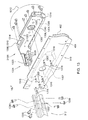
Figure 12 is a fragmentary exploded perspective view of the right rear corner of the lower sieve frame ofFigure 3 . -
Figure 13 is a fragmentary exploded perspective view of the right front corner of the lower sieve frame ofFigure 3 . - In the discussion herein, the terms "side-to-side", "sideways", "laterally" or "lateral" refer to a direction that is perpendicular to a direction of travel "V" of the agricultural harvester on which the reciprocating sieve assemblies are mounted as the agricultural harvester travels through the field harvesting crops. The terms "in front of", "front", "forward", "fore" and the like refer to the direction of travel "V". The terms "back", "rear", "behind", "to the rear of" and the like refer to a direction opposite to the direction of travel "V". The terms "inner", "inward" or "inwardly" refer to a lateral direction toward the lateral midpoint of the reciprocating sieve assemblies. The terms "outer", "outward" or "outwardly" refer to a lateral direction away from the lateral midpoint of the reciprocating sieve assemblies. The term "sieve" refers to a sieve, chaffer, screen or other device for separating grain from MOG that is configured to function by the passing of an air stream upward therethrough. The term "fastener" refers to blind fasteners and tubular fasteners, such as bolts, screws, rivets, and rivnuts. In particular, if the fasteners are rivets they may be tubular rivets, typical of the type sold under brand names such as "Magna-Lok" and "Pop Rivets". "Tubular rivets" as that term is used herein refers to a tubular body with an outwardly extending flange at one end. A rod extends down the center of the tubular body. The rod has a head at one end. The tubular rivet is employed by inserting the rivet body into rivet holes and extracting the rod. The head is then pulled through the tubular body causing the tubular body to expand. This expansion causes the tubular body to abut the rivet holes thereby fixing the rivet in place.
- In
Figure 1 , acleaning shoe 100 comprises afan 102, ahousing 104, andupper sieve assembly 106, alower sieve assembly 108,hangers 110,hangers 112, amotor 114, and a drive crank 116. -
Fan 102 extends laterally across substantially the entire width of the cleaning shoe. It generates an airflow that travels rearward toward theupper sieve assembly 106 and thelower sieve assembly 108. This air is conveyed upward through theupper sieve assembly 106 and thelower sieve assembly 108, levitating MOG and carrying it rearward and out of the agricultural harvester. - The
housing 104 supports the fan and themotor 114. Theupper sieve assembly 106 comprises aframe 118 that is generally rectangular and anupper sieve 120 that is supported in theframe 118. Thelower sieve assembly 108 comprises aframe 122 and a lower sieve 124 that is supported in theframe 122. - Each
hanger 110 has an upper end and a lower end. The upper end is pivotally coupled to the chassis (not shown) of the agricultural harvester. The lower end is pivotally coupled to theupper sieve assembly 106. By this arrangement, theupper sieve assembly 106 is suspended to pivot generally fore and aft. Thehangers 110 are disposed in a generally rectangular arrangement, to support the left front, left rear, right front, and right rear of theupper sieve assembly 106. Thus, thehangers 110 are disposed at and support theupper sieve assembly 106 at the four corners of theupper sieve assembly 106 disposed at and support theupper sieve assembly 106 at the four corners of theupper sieve assembly 106. - Each
hanger 112 has an upper end and a lower end. The upper end is pivotally coupled to the chassis (not shown) of the agricultural harvester. The lower end is pivotally coupled to thelower sieve assembly 108. By this arrangement theupper sieve assembly 106 is suspended to pivot generally fore-and-aft. Thehangers 112 are disposed in a generally rectangular arrangement to support the left front, left rear, right front, and right rear of the lower sieve assembly. Thus, thehangers 112 are disposed at and support thelower sieve assembly 108 at the four corners of thelower sieve assembly 108. - The
upper sieve 120 comprises asieve frame 126 that supports a fore-and-aft extending array of laterally extendingslats 128. Thesieve frame 126 is generally rectangular and is removably supported in theframe 118 of theupper sieve assembly 106. Theslats 128 extend laterally and parallel to each other and are disposed in a fore-and-aft extending array. Theslats 128 are pivotally supported at their opposing ends on thesieve frame 126 to pivot with respect to thesieve frame 126 about their respective longitudinal and laterally extending axes. - The lower sieve 124 comprises a sieve frame 130 and slats (not shown) that are constructed the same as the
upper sieve 120. The sieve frame 130 is generally rectangular and is removably supported in theframe 122 of thelower sieve assembly 108. The slats of the lower sieve 124 (not shown) are configured, arranged, and supported in the sieve frame 130 the same as theslats 128 are supported in thesieve frame 126 of theupper sieve 120. - In
Figure 2 , theupper sieve assembly 106 is shown with theupper sieve 120 removed. Thelower sieve assembly 108 is shown with the lower sieve 124 removed. The upper ends of thehangers 110 and thehangers 112 are stationary, and are fixed to the chassis of the agricultural harvester. The lower ends of thehangers 110 and the lower ends of thehangers 112 pivot fore-and-aft. Themotor 114 is driven in rotation causing aneccentric hub 200 mounted on the end of themotor 114, to rotate off-center. Theeccentric hub 200 is supported on a bearing at the forward end of the drive crank 116, which causes the forward end of the drive crank 116 to follow an eccentric path. - A first
rear portion 202 of the drive crank 116 is coupled to a central region of thehanger 112. A second rear portion 204 of the drive crank 116 is coupled to a central region of thehanger 110. - As first
rear portion 202 and the second rear portion 204 of the drive crank 116 are driven fore-and-aft in reciprocating movement, they cause the lower ends of thehangers 112 and the lower ends of thehangers 110, respectively, to pivot in a shallow arc, in a generally fore and aft direction. - Referring to the
upper sieve assembly 106, the lower end of eachforward hanger 110 is rotationally coupled to a correspondingforward hanger mount 206. The lower end of eachrear hanger 110 is rotationally coupled to a correspondingrear hanger mount 208. - Referring to the
lower sieve assembly 108, the lower end of eachforward hanger 112 is rotationally coupled to a correspondingforward hanger mount 210. The lower end of eachrear hanger 112 is rotationally coupled to a correspondingrear hanger mount 212 - The two forward hanger mounts 206 are mirror images of each other. The two rear hanger mounts 208 are mirror images of each other. The two forward hanger mounts 210 are mirror images of each other. The two rear hanger mounts 212 are mirror images of each other.
- Bearings, bushings, and/or other resilient members are disposed between the lower ends of the
hangers 110 and thehangers 112 and the respective hanger mounts. These bearings, bushings, and/or other resilient members permit the small relative movement between thehangers 110 in thehangers 112 in their respective hanger mounts as theupper sieve assembly 106 and thelower sieve assembly 108 are reciprocated fore-and-aft. -
Brackets 214 andbrackets 216 are fixed along their respective upper edges to a plurality ofapertures 218. Theapertures 218 are formed in a lower portion of theelongate member 308, and are formed in a lower portion of the elongate member 310 (Figure 3 ).Apertures 218 are spaced apart, generally evenly, and are oriented in a line extending along the lower portion of theelongate member 308 and the lower portion of the elongate member 310 (Figure 3 ). - A plurality of fasteners 220 is provided to attach the
brackets 214 and thebrackets 216 to theelongate member 308 and theelongate member 310. Each of a plurality of fasteners 220 extends through a corresponding one of the plurality ofapertures 218 and also extends through a corresponding one of a plurality of apertures 221. The plurality of apertures 221 are formed in the upper edges of thebrackets 214 and thebrackets 216. - The
brackets 214 and thebrackets 216 are oriented generally vertically. Thebrackets 214 and thebrackets 216 extend downward below the bottom ofelongate member 308 and the bottom ofelongate member 310. Thebrackets 214 and thebrackets 216 are fixed at their lower ends to opposing lateral sides of agrain pan 222 and agrain pan 224, respectively. - The
grain pan 222 and thegrain pan 224 are generally planar and extend both laterally and fore and aft. Thegrain pan 222 and thegrain pan 224 are supported by thebrackets 214 and thebrackets 216, respectively, to be disposed at least partially below the bottom ofelongate member 308 and the bottom ofelongate member 310. In this position, they are configured to receive grain that has passed through and has fallen downward from the lower sieve (124). - The
brackets 214 and thebrackets 216 are configured to support thegrain pan 222 and thegrain pan 224 at a downwardly and forwardly sloping angle with respect to the longitudinal direction of theelongate member 308 and theelongate member 310. - The
brackets 214, thebrackets 216, thegrain pan 222, and thegrain pan 224 are made of sheet metal, more particularly ferrous sheet metal, and more particularly rolled steel sheet metal. Thebrackets 214, thebrackets 216, thegrain pan 222 and thegrain pan 224 may be made of high-strength sheet metal having a strength of at least 30 kilo pounds per square inch (kpsi), more preferably at least 50 kpsi, and more preferably at least 80 kpsi. -
Figure 3 illustrates theframe 118 for theupper sieve assembly 106 and theframe 122 for thelower sieve assembly 108. - The
frame 118 is generally rectangular, and comprises anelongate member 300 that extends fore-and-aft and forms the left side of theframe 118, anelongate member 302 that extends fore and aft and forms the right side of theframe 118, anelongate cross member 304 that extends laterally and forms the front side of theframe 118, and anelongate cross member 306 that extends laterally and forms the rear side of theframe 118. - Similarly, the
frame 122 is generally rectangular, and comprises anelongate member 308 that extends fore-and-aft informs the left side of theframe 122, andelongate member 310 that extends fore-and-aft and forms the right side of theframe 122, anelongate cross member 312 that extends laterally and forms the front side of theframe 122, and anelongate cross member 314 that extends laterally and forms the rear side of theframe 122. - The
elongate member 300, theelongate member 302, theelongate cross member 304, theelongate cross member 306, theelongate member 308, theelongate member 310, theelongate cross member 312, and theelongate cross member 314 are extruded members. They are comprised of a light metal such as aluminum, magnesium, titanium, or alloys thereof. - The
elongate member 300 and theelongate member 302 are mirror images of each other. Theelongate member 308 and theelongate member 310 are mirror images of each other. - The
hanger mount 206L is fixed to the forward end of theelongate member 300 with a plurality offasteners 316. Thehanger mount 206R is fixed to the forward end of theelongate member 302 with a plurality offasteners 318. Thehanger mount 208L is fixed to the rear end of theelongate member 300 with a plurality offasteners 320. Thehanger mount 208R is fixed to the rear end of theelongate member 302 with a plurality offasteners 322. - The
hanger mount 210L is fixed to the forward end of theelongate member 308 with a plurality offasteners 324 thehanger mount 210R is fixed to the forward end of theelongate member 310 with a plurality offasteners 326. Thehanger mount 212L is fixed to the rear end of theelongate member 308 with a plurality offasteners 328. Thehanger mount 212R is fixed to the rear end of theelongate member 310 with a plurality offasteners 330. - Gaskets, adhesives, spacers or other arrangements may be provided between the hanger mounts and the elongate members to provide a more rigid connection and reduce chafing and wear between the hanger mounts and the elongate members.
-
Figure 4 illustrates a cross-section of theelongate member 308.Elongate member 308 is elongate in a vertical direction "V". Theelongate member 308 has atubular center section 400 with anouter wall 402 and aninner wall 404 that are generally parallel and define the two elongate and vertical sides of thetubular center section 400.Elongate member 308 has a vertically extendingupper flange 406 that extends from the upper part of thetubular center section 400. Theelongate member 308 has a vertically extendinglower flange 408 that extends from the lower part of thetubular center section 400. - The
tubular center section 400 defines a hollow interior region 412 that is taller than it is wide. In one arrangement, the hollow interior region 412 is at least three times as tall as it is wide. In an alternative arrangement it is at least five times as tall as it is wide. In an alternative arrangement it is at least seven times as tall as it is wide. In an alternative arrangement it is at least nine times as tall as it is wide. These alternative arrangements can be shown by shortening or lengthening in a vertical direction theouter wall 402 and theinner wall 404. Theelongate member 308 is an extrusion, and therefore all of the walls shown in the cross-section extend substantially the entire length of theelongate member 308 except in regions where they have been machined away by subsequent machining operations. -
Figure 5 illustrates a cross-section of theelongate member 300.Elongate member 300 is elongate in a vertical direction "V".Elongate member 300 has atubular center section 500 with anouter wall 502 and aninner wall 504 that are generally parallel and define the two elongate and vertical sides of thetubular center section 500.Elongate member 300 has a vertically extendinglower flange 508 that extends from the lower part of thetubular center section 500. - The
tubular center section 500 defines a hollow interior that is at least three times taller than it is wide. In an alternative arrangement it is at least five times as tall as it is wide. In an alternative arrangement is at least seven times as tall as it is wide. In an alternative arrangement it is at least nine times as tall as it is wide. In an alternative arrangement it is at least 12 times as tall as it is wide. - A
strut 510 extends between and is fixed to theouter wall 502 and theinner wall 504. Thestrut 510 is oriented generally horizontally and perpendicular to theouter wall 502 andinner wall 504. Thestrut 510 divides thetubular center section 500 into twosubsections -
Figure 6 illustrates a cross-section of theelongate cross member 312.Elongate cross member 312 extends and is elongate in a lateral direction. The longitudinal extent ofelongate cross member 312 is normal (Figure 3 ) to the inner and outer surfaces of theinner wall 404 and the inner and outer surfaces of theouter wall 402 ofelongate member 308 andelongate member 310.Elongate cross member 312 is formed as an elongate extrusion having a hollowinterior region 600 that extends over substantially its entire length.Elongate cross member 312 has a constant cross-sectional profile over substantially its entire length. Anexterior wall 602 faces rearward and is provided with a rear-facingelongate recess 604 that extends over substantially its entire length. The rear-facingelongate recess 604 is configured to receive and support an elongate and laterally extending leading edge of the lower sieve frame 130. Astrut 606 is provided between afirst wall 608 and asecond wall 610 of theelongate cross member 312. Thestrut 606 serves to provide rigidity to theelongate cross member 312 and to divide the hollowinterior region 600 into afirst region 612 and asecond region 614. Thefirst wall 608 forms a part of the outwardly facing surface of theelongate cross member 312. Thesecond wall 610 forms a part of the rear-facingelongate recess 604. The hollowinterior region 600 defines an enclosedinterior surface 616 which abuts and is fixed against corresponding surfaces on the hangar mounts 210 (e.g. 210L and 210R). -
Figure 7 illustrates a cross-section of theelongate cross member 304.Elongate cross member 304 extends and is elongate in a lateral direction. The longitudinal extent ofelongate cross member 304 is normal (Figure 3 ) to the inner and outer surfaces of theouter wall 502 and the inner and outer surfaces of theinner wall 504 ofelongate member 300 and ofelongate member 302. -
Elongate cross member 304 is formed as an elongate extrusion having a hollowinterior region 700 that extends over substantially its entire length.Elongate cross member 304 has a constant cross sectional profile over substantially its entire length. Anexterior wall 702 faces rearward and is provided with a rear-facing andelongate recess 704 that extends over substantially its entire length. Theelongate recess 704 is configured to receive and support an elongate and laterally extending leading edge of theupper sieve frame 126. The hollowinterior region 700 defines an enclosedinterior surface 706 which abuts and is fixed against corresponding surfaces on the hanger mounts 206 (e.g. 206L and 206R). -
Figure 8 illustrates a cross-section of theelongate cross member 314.Elongate cross member 314 extends and is elongate in a lateral direction. The longitudinal extent ofelongate cross member 314 is normal (Figure 2 ) to the inner and outer surfaces of theinner wall 404 and the inner and outer surfaces of theouter wall 402 of theelongate member 308 and of theelongate member 310.Elongate cross member 314 is formed as an elongate extrusion having a hollowinterior region 800 that extends over substantially its entire length.Elongate cross member 314 has a constant cross sectional profile over substantially its entire length. Anexterior wall 802 faces upwardly and is provided with an upward-facingelongate recess 804 that extends over substantially its entire length. The upward-facingelongate recess 804 is configured to receive and support an elongate and laterally extending trailing edge of the lower sieve frame 130. The hollowinterior region 800 defines an enclosedinterior surface 806 which abuts and is fixed against corresponding surfaces on the hangar mounts 212 (e.g. 212L and 212R). -
Figure 9 illustrates a cross-section of theelongate cross member 306.Elongate cross member 306 extends and is elongate in a lateral direction. The longitudinal extent ofelongate cross member 306 is normal (Figure 3 ) toinner wall 404 andouter wall 402 ofelongate member 300 andelongate member 302.Elongate cross member 306 is formed as an elongate extrusion having a hollowinterior region 900 that extends over substantially its entire length.Elongate cross member 306 has a constant cross sectional profile over substantially its entire length. Anexterior wall 902 faces upwardly and is provided with an upward facing anelongate recess 904 that extends over substantially its entire length. Theelongate recess 904 is configured to receive and support an elongate and laterally extending trailing edge of theupper sieve frame 126. The hollowinterior region 900 defines an enclosedinterior surface 906 which abuts and is fixed against corresponding surfaces on the hangar mounts 208 (e.g. 208L and 208R). -
Figure 10 is an exploded view of thehanger mount 208R, theelongate member 302, and theelongate cross member 306 together with the plurality offasteners 322. Thehanger mount 208R is identical in construction to thehanger mount 208L, but is a mirror image. Thus, the hanger mount and fastener arrangement of the rear ofelongate member 302 shown inFigure 10 is functionally and structurally identical to the hanger mount and fastener arrangement at the rear of theelongate member 300. -
Hanger mount 208R is comprised of metal, for example a ferrous metal, such as steel, iron, or nodular iron. It may also be a light metal alloy.Hanger mount 208R has ahanger connection 1000 that is configured to be coupled to and support the hanger 110 (Figure 2 ) for reciprocating movement with respect to thehanger mount 208R. Thehanger mount 208R is configured to be received inside anaperture 1002 that is machined into theouter wall 502 of the elongate member. - The
hanger mount 208R defines a first,inner flange 1004 has a generally planar mounting surface 1006 that is configured to abut and be fixed against theinner wall 504. Thehanger mount 208R defines a second, outer flange 1008 that defines a generally planar mounting surface 1010 that is configured to abut and be fixed against theouter wall 502. The portion of the generally planar mounting surface 1006 that abuts theinner wall 504 and the portion of the generally planar mounting surface 1010 that abuts inside surface of theouter wall 502 are parallel. - The plurality of
fasteners 322 includes a first plurality offasteners 1012, (shown as blind rivets), that extend through a corresponding plurality ofapertures 1014 formed in the second, outer flange 1008 and are received into a corresponding plurality ofapertures 1016 formed in theouter wall 502 ofelongate member 302. The plurality offasteners 322 includes a second plurality offasteners 1018 that are configured to extend through a corresponding plurality ofapertures 1020 formed in theinner wall 504 and are received into a corresponding plurality ofapertures 1022 in the first,inner flange 1004. Thus, thehanger mount 208R is fixed to theelongate member 302. Each of the first plurality offasteners 1012 and the second plurality offasteners 1018 have longitudinal axes that are parallel and extend laterally, parallel to the longitudinal extent of theelongate cross member 306. - The
hanger mount 208R defines an elongate, laterally-extendingmount 1024.Mount 1024 extends through anaperture 1026 in theelongate member 302. It is fixed at its outer end toinner flange 1004, and its inner end is cantilevered into the space between theelongate member 300 and theelongate member 302. Anouter surface 1025 of themount 1024 is configured to abut and be fixed against the enclosedinterior surface 906 of theelongate cross member 306. - The
outer surface 1025 of themount 1024 is preferably machined such that when themount 1024 is inserted into the free end of theelongate cross member 306, it is fitted closely to the enclosedinterior surface 906. Theouter surface 1025 extends in a transverse direction and normal to the surfaces of theinner wall 504 and theouter wall 502 to which thehanger mount 208R is also fixed. Theouter surface 1025 comprises a plurality (4) of flat surfaces that are joined to adjacent flat surfaces at corners. The flat surfaces are machined after thehanger mount 208R has been cast. Each of the flat surfaces is disposed at an angle to its adjacent flat surfaces. - The
mount 1024 has a plurality (8) ofapertures 1028 passing therein that are configured to receive a corresponding third plurality offasteners 1030 of the first plurality offasteners 322. Each of the flat surfaces that define theouter surface 1025 has two of theapertures 1028. - The
mount 1024 extends inwardly through theinner wall 504 far enough to be received in an open end of theelongate cross member 306. In this position, each of the three flat surfaces that define theouter surface 1025 abuts a corresponding and parallel flat surface defined on the inside surface of theelongate cross member 306. The third plurality of fasteners 1030 (shown here as bolts) extend through a plurality ofapertures 1032. The plurality ofapertures 1032 extend through the outer wall ofelongate cross member 306 and into the hollowinterior region 900 of theelongate cross member 306. Having passed through the plurality ofapertures 1032, the third plurality offasteners 1030 are fixed to themount 1024 by being received in plurality ofapertures 1028. In this manner, fasteners extend through the wall of theelongate cross member 306, and are fixed to themount 1024, thereby securing themount 1024 to theelongate cross member 306. -
Figure 11 is an exploded view of thehanger mount 206R, theelongate member 302, and theelongate cross member 304 together with the plurality offasteners 318. Thehanger mount 206R is identical in construction to thehanger mount 206L, but is a mirror image. Thus, the hanger mount and fastener arrangement of the front ofelongate member 302 shown inFigure 11 is functionally and structurally identical to the hanger mount and fastener arrangement at the front of theelongate member 300. -
Hanger mount 206R is comprised of metal, for example a ferrous metal, such as steel, iron, or nodular iron. It may also be a light metal alloy.Hanger mount 206R has a hanger connection 1100 that is configured to be coupled to and support the hanger 110 (Figure 2 ) for reciprocating movement with respect to thehanger mount 206R. Thehanger mount 206R is configured to be received inside anaperture 1102 that is machined into theouter wall 502 of theelongate member 302. - The
hanger mount 206R defines a first,inner flange 1104 has a generally planar mounting surface 1106 that is configured to abut and be fixed against theinner wall 504. Thehanger mount 206R defines a second, outer flange 1108 that defines a generally planar mounting surface 1110 that is configured to abut and be fixed against theouter wall 502. The portion of the generally planar mounting surface 1106 that abuts theinner wall 504 and the portion of the generally planar mounting surface 1110 that abuts inside surface of theouter wall 502 are parallel. - The plurality of
fasteners 318 includes a first plurality offasteners 1112, (shown as blind rivets), that extend through a corresponding plurality ofapertures 1114 formed in the second, outer flange 1108 and are received into a corresponding plurality ofapertures 1116 formed in theouter wall 502 ofelongate member 302. The plurality offasteners 318 includes a second plurality offasteners 1118 that are configured to extend through a corresponding plurality ofapertures 1120 formed in theinner wall 504 and are received into a corresponding plurality ofapertures 1122 in the first,inner flange 1104. Thus, thehanger mount 206R is fixed to theelongate member 302. Each of the first plurality offasteners 1112 and the second plurality offasteners 1118 have longitudinal axes that are parallel and extend laterally, parallel to the longitudinal extent of theelongate cross member 304. - The
hanger mount 206R defines an elongate, laterally-extendingmount 1124.Mount 1124 extends through anaperture 1126 in theelongate member 302. It is fixed at its outer end toinner flange 1104, and its inner end is cantilevered into the space between theelongate member 300 and theelongate member 302. Anouter surface 1125 of themount 1124 is configured to abut and be fixed against the enclosedinterior surface 706 of theelongate cross member 304. Theouter surface 1125 of themount 1124 is preferably machined such that when themount 1124 is inserted into the free end of theelongate cross member 304, it is fitted closely to the enclosedinterior surface 706. Theouter surface 1125 extends in a transverse direction and normal to the surfaces of theinner wall 504 and theouter wall 502 to which thehanger mount 206R is also fixed. Theouter surface 1125 comprises a plurality (3) of flat surfaces that are joined to adjacent flat surfaces at corners. The flat surfaces are machined after thehanger mount 206R has been cast. Each of the flat surfaces is disposed at an angle to its adjacent flat surfaces. - The
mount 1124 has a plurality (6) ofapertures 1128 passing therein that are configured to receive a corresponding third plurality offasteners 1130 of the first plurality offasteners 318. Each of the flat surfaces that define theouter surface 1125 has two of theapertures 1128. - The
mount 1124 extends inwardly through theinner wall 504 far enough to be received in an open end of theelongate cross member 304. In this position, each of the three flat surfaces that define theouter surface 1125 abuts a corresponding and parallel flat surface defined on the inside surface of theelongate cross member 304. The third plurality of fasteners 1130 (shown here as bolts) extend through a plurality ofapertures 1132. The plurality ofapertures 1132 extend through the outer wall ofelongate cross member 304 and into the hollowinterior region 700 of theelongate cross member 304. Having passed through the plurality ofapertures 1132, the third plurality offasteners 1130 are fixed to themount 1124 by being received in plurality ofapertures 1128. In this manner, fasteners extend through the wall of theelongate cross member 304, and are fixed to themount 1124, thereby securing themount 1124 to theelongate cross member 304. -
Figure 12 is an exploded view of thehanger mount 212R, theelongate member 302, and theelongate cross member 314 together with the plurality offasteners 322. Thehanger mount 212R is identical in construction to thehanger mount 212L, but is a mirror image. Thus, the hanger mount and fastener arrangement of the rear ofelongate member 310 shown inFigure 12 is functionally and structurally identical to the hanger mount and fastener arrangement at the rear of theelongate member 308. -
Hanger mount 212R is comprised of metal, for example a ferrous metal, such as steel, iron, or nodular iron. It may also be a light metal alloy.Hanger mount 212R has ahanger connection 1200 that is configured to be coupled to and support the hanger 112 (Figure 2 ) for reciprocating movement with respect to thehanger mount 212R. Thehanger mount 212R is configured to be received inside anaperture 1202 that is machined into theouter wall 502 of the elongate member. - The
hanger mount 212R defines a first,inner flange 1204 has a generally planar mounting surface 1206 that is configured to abut and be fixed against theinner wall 404. Thehanger mount 212R defines a second, outer flange 1208 that defines a generally planar mounting surface 1210 that is configured to abut and be fixed against theouter wall 402. The portion of the generally planar mounting surface 1206 that abuts theinner wall 404 and the portion of the generally planar mounting surface 1010 that abuts inside surface of theouter wall 402 are parallel. - The plurality of
fasteners 330 includes a first plurality offasteners 1212, (shown as blind rivets), that extend through a corresponding plurality ofapertures 1214 formed in the second, outer flange 1208 and are received into a corresponding plurality ofapertures 1216 formed in theouter wall 402 ofelongate cross member 314. The plurality offasteners 330 includes a second plurality offasteners 1218 that are configured to extend through a corresponding plurality ofapertures 1220 formed in theinner wall 404 and are received into a corresponding plurality ofapertures 1222 in the first,inner flange 1204. Thus, thehanger mount 212R is fixed to theelongate cross member 314. Each of the first plurality offasteners 1212 and the second plurality offasteners 1218 have longitudinal axes that are parallel and extend laterally, parallel to the longitudinal extent of theelongate cross member 314. - The
hanger mount 212R defines an elongate, laterally-extendingmount 1224.Mount 1224 extends through anaperture 1226 in theelongate member 310. It is fixed at its outer end toinner flange 1204, and its inner end is cantilevered into the space between theelongate member 308 and theelongate member 310. Anouter surface 1225 of themount 1224 is configured to abut and be fixed against the enclosedinterior surface 806 of theelongate cross member 314. Theouter surface 1225 of themount 1224 is preferably machined such that when themount 1224 is inserted into the free end of theelongate cross member 314, it is fitted closely to the enclosedinterior surface 806. Theouter surface 1225 extends in a transverse direction and normal to the surfaces of theinner wall 404 and theouter wall 402 to which thehanger mount 212R is also fixed. Theouter surface 1225 comprises a plurality (3) a flat surfaces that are joined to adjacent flat surfaces at corners. The flat surfaces are machined after thehanger mount 212R has been cast. Each of the flat surfaces is disposed at an angle to its adjacent flat surfaces. - The
mount 1224 has a plurality ofapertures 1228 passing therein that are configured to receive a corresponding third plurality offasteners 1230 of the first plurality offasteners 330. Each of the flat surfaces that define theouter surface 1225 has two of theapertures 1228. - The
mount 1224 extends inwardly through theinner wall 404 far enough to be received in an open end of theelongate cross member 314. In this position, each of the three flat surfaces that define theouter surface 1225 abuts a corresponding and parallel flat surface defined on the inside surface of theelongate cross member 314. The third plurality of fasteners 1230 (shown here as bolts) extend through a plurality ofapertures 1232. The plurality ofapertures 1232 extend through the outer wall ofelongate cross member 314 and into the hollow interior region 412 of theelongate cross member 314. Having passed through the plurality ofapertures 1232, the third plurality offasteners 1230 are fixed to themount 1224 by being received in the plurality ofapertures 1228. In this manner, fasteners extend through the wall of theelongate cross member 314, and are fixed to themount 1224, thereby securing themount 1224 to theelongate cross member 314. -
Figure 13 is an exploded view of thehanger mount 210R, theelongate member 310, and theelongate cross member 312 together with the plurality offasteners 326. Thehanger mount 210R is identical in construction to thehanger mount 210L, but is a mirror image. Thus, the hanger mount and fastener arrangement of the front ofelongate member 310 shown inFigure 13 is functionally and structurally identical to the hanger mount and fastener arrangement at the front of theelongate member 308. -
Hanger mount 210R is comprised of metal, for example a ferrous metal, such as steel, iron, or nodular iron. It may also be a light metal alloy.Hanger mount 210R has ahanger connection 1300 that is configured to be coupled to and support the hanger 112 (Figure 2 ) for reciprocating movement with respect to thehanger mount 210R. Thehanger mount 210R is configured to be received inside anaperture 1302 that is machined into theouter wall 402 of the elongate member. - The
hanger mount 210R defines a first, inner flange 1304 has a generally planar mounting surface 1306 that is configured to abut and be fixed against theinner wall 404. Thehanger mount 210R defines a second, outer flange that defines a generally planar mounting surface 1310 that is configured to abut and be fixed against theouter wall 402. The portion of the generally planar mounting surface 1306 that abuts theinner wall 404 and the portion of the generally planar mounting surface 1310 that abuts inside surface of theouter wall 402 are parallel. - The plurality of
fasteners 1318 includes a first plurality offasteners 1312, (shown as blind rivets), that extend through a corresponding plurality ofapertures 1314 formed in the second, outer flange 1308 and are received into a corresponding plurality ofapertures 1316 formed in theouter wall 402 ofelongate member 310. The plurality offasteners 326 includes a second plurality offasteners 1318 that are configured to extend through a corresponding plurality ofapertures 1320 formed in theinner wall 404 and are received into a corresponding plurality ofapertures 1322 in the first, inner flange 1304. Thus, thehanger mount 210R is fixed to theelongate member 310. Each of the first plurality offasteners 1312 and the second plurality offasteners 1318 have longitudinal axes that are parallel and extend laterally, parallel to the longitudinal extent of theelongate cross member 312. - The
hanger mount 210R defines an elongate, laterally-extendingmount 1324.Mount 1324 is fixed at its outer end to inner flange 1304, and its inner end is cantilevered into the space between theelongate member 308 and theelongate member 310. Anouter surface 1325 of themount 1324 is configured to abut and be fixed against the enclosedinterior surface 616 of theelongate cross member 312. Theouter surface 1325 of themount 1324 is preferably machined such that when themount 1324 is inserted into the free end of theelongate cross member 312, it is fitted closely to the enclosedinterior surface 616. Theouter surface 1325 extends in a transverse direction and normal to the surfaces of theinner wall 404 and theouter wall 402 to which thehanger mount 210R is also fixed. Theouter surface 1325 comprises a plurality (3) of flat surfaces that are joined to adjacent flat surfaces at corners. The flat surfaces are machined after thehanger mount 210R has been cast. Each of the flat surfaces is disposed at an angle to its adjacent flat surfaces. - The
mount 1324 has a plurality (7) ofapertures 1328 passing therein that are configured to receive a corresponding third plurality offasteners 1330 of the first plurality offasteners 326. Two of the flat surfaces that define theouter surface 1325 have two of theapertures 1028. One of the flat surfaces that defines theouter surface 1325 has three of theapertures 1028. - The
mount 1324 extends inwardly through theinner wall 404 far enough to be received in an open end of theelongate cross member 312. In this position, each of the three flat surfaces that define theouter surface 1325 abuts a corresponding and parallel flat surface defined on the inside surface of theelongate cross member 312. The third plurality of fasteners 1330 (shown here as bolts) extend through a plurality ofapertures 1332. The plurality ofapertures 1332 extend through the outer wall ofelongate cross member 312 and into the hollow interior region 412 of theelongate cross member 312. Having passed through the plurality ofapertures 1332, the third plurality offasteners 1330 are fixed to themount 1324 by being received in plurality ofapertures 1328. In this manner, fasteners extend through the wall of theelongate cross member 312, and are fixed to themount 1324, thereby securing themount 1324 to theelongate cross member 312. - All eight of the hanger mounts are connected to their respective longitudinally extending elongate members and transversely extending elongate cross members in a particularly advantageous arrangement.
- This arrangement is particularly advantageous in that it permits each hanger mount to serve as a common support for both the longitudinally extending elongate member and the transversely extending elongate cross member to which it is fixed. This arrangement reduces assembly time and machining operations. Each hanger mount provides a common connection between its associated longitudinally extending elongate member and transversely extending elongate cross member. Each hanger mount is coupled to both an associated longitudinally extending elongate member and an associated transversely extending elongate cross member.
- Loads applied to longitudinally extending elongate members are transmitted directly to the hanger mounts. Loads applied to the transversely extending elongate cross members are also transmitted directly to the hanger mounts.
- In contrast to this, prior art arrangements transmitted the loads from the laterally extending frame members to the longitudinally extending frame members, and from the longitudinally extending frame members to the hanger mounts. Thus, the longitudinally extending frame members had to be constructed sufficiently strong to not only support loads applied to them directly, but also to support and convey loads applied to the laterally extending frame members.
- Further advantages are achieved by providing a hanger mount having a first, inner flange fixed to an inner wall of a longitudinally extending elongate member and a second, outer flange fixed to the outer wall of the same longitudinally extending elongate member, the hanger mount is capable of transmitting loads to both the inner wall and the outer wall of a tubular section of the longitudinally extending elongate member.
- This arrangement distributes the load more evenly into the longitudinally extending elongate member. Further, this arrangement holds the inner wall and the outer wall a predetermined distance apart, and therefore helps prevent the longitudinally extending elongate member from buckling under loads. Such buckling could cause the inner wall and the outer wall to either collapse toward or away from each other. By separately fixing the hanger mount to the inner wall and to the outer wall the spacing between the inner wall and the outer wall is maintained constant even under relatively high loads.
- Further advantages are achieved by fastening each hanger mount to the longitudinally extending elongate member with fasteners that extend into and terminate within their respective tubular sections, such as the hollow interior region provided in all of the longitudinally extending elongate members and laterally extending elongate cross members, the ends of the fasteners are protected from the environment and thus are less likely to experience corrosion and the weakening of the mechanical connection between the blind rivets and the wall of the
elongate member 302. This is of particular concern given the cyclical loads applied by thehangers frames lower sieve assemblies - Further advantages are achieved by providing longitudinally extending elongate members to form the fore-and-aft side members of the sieve frame. This permits the side members to be made lighter.
Claims (15)
- A reciprocating sieve frame (118, 122) for an agricultural combine, wherein the agricultural combine has a direction of travel (V) through the field harvesting crops, the reciprocating sieve frame (118, 122) comprising:a first member (300, 302, 308, 310) that is elongate and has a first end and a second end,wherein the first member extends generally horizontally and in the direction of travel;a second member (300, 302, 308, 310) that is elongate and has a first end and a second end, wherein the second member extends generally horizontally and in the direction of travel,wherein the second member is spaced away from the first member a first distance, andwherein the second member is disposed generally parallel to the first member;a first cross member (304, 306, 312, 314) that is elongate and has a first end and a second end, wherein the first cross member extends longitudinally in a direction that is perpendicular to the direction of travel, wherein said first end of said first cross member is fixed with respect to the first member, wherein said second end of said first cross member is fixed with respect to the second member; anda second cross member (304, 306, 312, 314) that is elongate and has a first end and a second end, wherein the second cross member extends longitudinally in a direction that is perpendicular to the direction of travel, wherein said first end of said second cross member is fixed with respect to the first member, wherein said second end of said second cross member is fixed with respect to the second member;characterized in that the first member is an extrusion, and that the second member is an extrusion.
- The reciprocating sieve frame of Claim 1, wherein the first cross member (304, 306, 312, 314) is an extrusion, and wherein the second cross member (304, 306, 312, 314) is an extrusion.
- The reciprocating sieve frame of Claim 1, wherein the first member (300, 302, 308, 310) is taller than it is wide, and wherein the second member (300, 302, 308, 310) is taller than it is wide.
- The reciprocating sieve frame of Claim 1, wherein the first member (300, 302, 308, 310) defines a first cross-sectional profile that is perpendicular to an extrusion direction of the first member, and further wherein the first cross-sectional profile defines a first tubular section (400, 500).
- The reciprocating sieve frame of Claim 4, wherein the first tubular section (400, 500) is taller than it is wide.
- The reciprocating sieve frame of Claim 4, wherein the first tubular section (500) further comprises a first tubular subsection (514) and a second tubular subsection (512), and further wherein the first tubular subsection is disposed above the second tubular subsection.
- The reciprocating sieve frame of Claim 6, wherein the first tubular subsection (514) is taller than it is wide, and further wherein the second tubular subsection (512) is taller than it is wide.
- The reciprocating sieve frame of Claim 1, wherein the first member (300, 302, 308, 310) has a first aperture (1002, 1102, 1202, 1302) that extends into the first member in a lateral direction, wherein said first aperture is configured to receive a hanger mount (206, 208, 210, 212).
- The reciprocating sieve frame of Claim 8, wherein the first member (300, 302, 308, 310) has a plurality of second apertures (1016, 1116, 1216, 1316) that extend into the first member in a lateral direction and that are disposed in a spaced-apart array extending about a periphery of the first aperture (1002, 1102, 1202, 1302).
- The reciprocating sieve frame of Claim 9, wherein each aperture of the plurality of second apertures (1016, 1116, 1216, 1316) is configured to receive a first fastener to fix the hanger mount (206, 208, 210, 212) to the first member (300, 302, 308, 310).
- The reciprocating sieve frame of Claim 10, wherein an extruded cross-section of the first member (300, 302, 308, 310) defines a tubular section (400, 500), and further wherein the tubular section is defined by an outer wall (402, 502) and an inner wall (404, 504) and further wherein the first aperture (1002, 1102, 1202, 1302) is formed in the outer wall, and further wherein each aperture of the plurality of second apertures (1016, 1116, 1216, 1316) is formed in the outer wall.
- The reciprocating sieve frame of Claim 11, wherein the first member (300, 302, 308, 310) has a plurality of third apertures (1020, 1120, 1220, 1320) formed in the inner wall (404, 504).
- The reciprocating sieve frame of Claim 12, wherein the plurality of second apertures (1016, 1116, 1216, 1316) are configured to receive fasteners to fix the hanger mount (206, 208, 210, 212) to the outer wall (402, 502) and not to the inner wall (404, 504), and further wherein the plurality of third apertures (1020, 1120, 1220, 1320) are configured to receive fasteners to fix the hanger mount to the inner wall (404, 504) and not to the outer wall (402, 502).
- The reciprocating sieve frame of Claim 8, wherein the first member (308, 310) has a plurality of fourth apertures (218) wherein each of the plurality of fourth apertures extends into the first member in a lateral direction, and further wherein the plurality of fourth apertures are configured to receive fasteners (220) that attach a grain pan (222, 224) to the first member.
- A combine comprising a reciprocating sieve frame according to one of the preceding claims.
Applications Claiming Priority (1)
| Application Number | Priority Date | Filing Date | Title |
|---|---|---|---|
| US14/032,767 US9198359B2 (en) | 2013-09-20 | 2013-09-20 | Frame for a reciprocating sieve |
Publications (2)
| Publication Number | Publication Date |
|---|---|
| EP2850936A1 true EP2850936A1 (en) | 2015-03-25 |
| EP2850936B1 EP2850936B1 (en) | 2017-04-19 |
Family
ID=51357801
Family Applications (1)
| Application Number | Title | Priority Date | Filing Date |
|---|---|---|---|
| EP14181136.4A Active EP2850936B1 (en) | 2013-09-20 | 2014-08-15 | Frame for a reciprocating sieve |
Country Status (7)
| Country | Link |
|---|---|
| US (1) | US9198359B2 (en) |
| EP (1) | EP2850936B1 (en) |
| CN (1) | CN104429399B (en) |
| AR (1) | AR097686A1 (en) |
| BR (1) | BR102014023099B1 (en) |
| CA (1) | CA2862949C (en) |
| EA (1) | EA201400888A1 (en) |
Families Citing this family (14)
| Publication number | Priority date | Publication date | Assignee | Title |
|---|---|---|---|---|
| DK3466432T3 (en) | 2014-05-15 | 2020-09-28 | Insmed Inc | PROCEDURES FOR THE TREATMENT OF PULMONAL NON-TUBERCULOSE MICOBACTERIAL INFECTIONS |
| GB201506557D0 (en) * | 2015-04-17 | 2015-06-03 | Agco Int Gmbh | Material conveyance system in a combine harvester |
| US10104839B2 (en) * | 2015-07-23 | 2018-10-23 | Cnh Industrial America Llc | Linkage for agricultural harvester cleaner |
| US10123486B2 (en) * | 2015-07-23 | 2018-11-13 | Cnh Industrial America Llc | Frame for agricultural harvester cleaner |
| US10064337B2 (en) * | 2015-08-28 | 2018-09-04 | Cnh Industrial America Llc | Grain pan and sieve dividers |
| CN105723955B (en) * | 2016-04-06 | 2018-05-25 | 山东常林农业装备股份有限公司 | Peanut combine vibrating screen dressing mechanism |
| US9901033B1 (en) | 2016-10-14 | 2018-02-27 | Deere & Company | Harvester louver wire retention system |
| CN106612996A (en) * | 2016-12-27 | 2017-05-10 | 江苏大学 | Combined harvester sorting sieve with sieve piece spacing and oblique angle adjustable |
| CN107135751A (en) * | 2017-06-15 | 2017-09-08 | 柳州市文宇科技服务有限公司 | A kind of broken fringe separator of crops grain |
| US10856469B2 (en) * | 2017-08-22 | 2020-12-08 | Hcc, Inc. | High strength sieve |
| JP2019162073A (en) * | 2018-03-20 | 2019-09-26 | ヤンマー株式会社 | Combine |
| US10827683B2 (en) | 2018-05-02 | 2020-11-10 | Cnh Industrial America Llc | Sieve assembly for a crop processing system of an agricultural harvester |
| CN112024364B (en) * | 2020-08-12 | 2021-12-21 | 海宁欣鼎商贸有限公司 | Automatic change automatic discharging sieving mechanism that crops differentiate according to size |
| CN113366976A (en) * | 2021-06-10 | 2021-09-10 | 中国农业科学院草原研究所 | Nettle seed harvesting and screening integrated device |
Citations (3)
| Publication number | Priority date | Publication date | Assignee | Title |
|---|---|---|---|---|
| US6412260B1 (en) * | 2000-10-25 | 2002-07-02 | Case Corporation | Direct drive system with a flywheel for an agricultural combine |
| US20030130019A1 (en) * | 2002-01-07 | 2003-07-10 | Hcc, Inc. | Slat and sieve assembly |
| US20080004092A1 (en) * | 2006-06-30 | 2008-01-03 | Deere & Company, A Delaware Corporation | Remote sieve or chaffer adjustment |
Family Cites Families (21)
| Publication number | Priority date | Publication date | Assignee | Title |
|---|---|---|---|---|
| US3334744A (en) * | 1965-09-22 | 1967-08-08 | Int Harvester Co | Sieve construction and the like |
| AT262911B (en) * | 1966-08-19 | 1968-07-10 | Binder Co Ag | Device for tensioning and fixing a sieve on a sieve frame |
| US3472377A (en) * | 1968-01-22 | 1969-10-14 | Case Co J I | Sieve for combine |
| US3606026A (en) | 1969-04-22 | 1971-09-20 | Mathews B C | Sieve mechanism for separating grain |
| US3800803A (en) * | 1973-02-08 | 1974-04-02 | Int Harvester Co | Combine sieve support |
| SU1064906A1 (en) | 1982-01-05 | 1984-01-07 | Всесоюзный Ордена Трудового Красного Знамени Научно-Исследовательский Институт Сельскохозяйственного Машиностроения Им.В.П.Горячкина | Grain combine harvester cleaning unit |
| US4632751A (en) * | 1982-11-15 | 1986-12-30 | Johnson Louis W | Shaker screen |
| DE3332763A1 (en) * | 1983-09-10 | 1985-03-28 | Claas Ohg, 4834 Harsewinkel | DEVICE FOR EVEN DISTRIBUTION OF GOODS IN SELF-DRIVING COMBINES |
| US5338257A (en) * | 1992-05-29 | 1994-08-16 | Probe Adventures, Inc. | Combine sieve distributor apparatus |
| DE10120957C2 (en) * | 2001-04-27 | 2003-04-24 | Ford New Holland Nv | Device for adjusting the sieve opening width on combine harvesters |
| US6790137B2 (en) * | 2002-01-25 | 2004-09-14 | Marvin James Gorden | High capacity air jet chaffer |
| US7654394B2 (en) * | 2004-06-14 | 2010-02-02 | Action Equipment Company, Inc. | Flexible mat screening or conveying apparatus |
| GB2415349A (en) * | 2004-06-22 | 2005-12-28 | Cnh Belgium Nv | Grain cleaning system for a combine harvester. |
| US20060270473A1 (en) * | 2004-08-19 | 2006-11-30 | James Straeter | Combine shoe with airflow-control |
| US7371162B2 (en) * | 2006-04-24 | 2008-05-13 | Cnh America Llc | Sieve adjustment mechanism for an agricultural combine |
| CN200990799Y (en) * | 2006-12-12 | 2007-12-19 | 福田雷沃国际重工股份有限公司 | Vibration-sieve sorting device for combined harvester |
| GB2450483A (en) * | 2007-06-25 | 2008-12-31 | Cnh Belgium Nv | A Grain cleaning system for a combine harvester |
| US8398469B2 (en) | 2008-07-09 | 2013-03-19 | Deere & Company | Agricultural work machine having an unloading system for unloading an agricultural product |
| US7927199B2 (en) * | 2008-07-16 | 2011-04-19 | Deere & Company | Grain cleaning assembly support frame movable in two planes |
| RU2439872C1 (en) | 2010-07-09 | 2012-01-20 | Федеральное государственное бюджетное образовательное учреждение высшего профессионального образования "Донской государственный технический университет" | Louver sieve of combine harvester cleaning and method of air supply to it |
| US9258945B2 (en) * | 2013-09-20 | 2016-02-16 | Deere & Company | Hanger mount for a reciprocating sieve |
-
2013
- 2013-09-20 US US14/032,767 patent/US9198359B2/en active Active
-
2014
- 2014-08-15 EP EP14181136.4A patent/EP2850936B1/en active Active
- 2014-09-09 EA EA201400888A patent/EA201400888A1/en unknown
- 2014-09-10 CA CA2862949A patent/CA2862949C/en active Active
- 2014-09-17 AR ARP140103457A patent/AR097686A1/en active IP Right Grant
- 2014-09-17 BR BR102014023099-8A patent/BR102014023099B1/en active IP Right Grant
- 2014-09-18 CN CN201410478308.7A patent/CN104429399B/en active Active
Patent Citations (3)
| Publication number | Priority date | Publication date | Assignee | Title |
|---|---|---|---|---|
| US6412260B1 (en) * | 2000-10-25 | 2002-07-02 | Case Corporation | Direct drive system with a flywheel for an agricultural combine |
| US20030130019A1 (en) * | 2002-01-07 | 2003-07-10 | Hcc, Inc. | Slat and sieve assembly |
| US20080004092A1 (en) * | 2006-06-30 | 2008-01-03 | Deere & Company, A Delaware Corporation | Remote sieve or chaffer adjustment |
Also Published As
| Publication number | Publication date |
|---|---|
| CA2862949A1 (en) | 2015-03-20 |
| BR102014023099B1 (en) | 2020-03-10 |
| CN104429399B (en) | 2019-07-19 |
| CN104429399A (en) | 2015-03-25 |
| AR097686A1 (en) | 2016-04-06 |
| EP2850936B1 (en) | 2017-04-19 |
| US9198359B2 (en) | 2015-12-01 |
| EA201400888A1 (en) | 2015-03-31 |
| CA2862949C (en) | 2021-08-10 |
| US20150087364A1 (en) | 2015-03-26 |
| BR102014023099A2 (en) | 2015-09-15 |
Similar Documents
| Publication | Publication Date | Title |
|---|---|---|
| EP2850936B1 (en) | Frame for a reciprocating sieve | |
| CA2864220C (en) | Hanger mount for a reciprocating sieve | |
| CA2863970C (en) | Lightweight hybrid material reciprocating sieve | |
| US4770190A (en) | Cleaning shoe screen for an agricultural combine having readily replaceable louvers | |
| US7553226B2 (en) | Grain cleaning system for a combine harvester | |
| US10757863B2 (en) | Device and method for changing cleaning shoe shaker arm angle | |
| US8622791B2 (en) | Cleaning shoe | |
| EP3120687B1 (en) | Side shaker link for agricultural harvester sieve assembly | |
| CN109937711A (en) | Combine harvester | |
| CN212520056U (en) | Vibrating screen of combine harvester | |
| US10123486B2 (en) | Frame for agricultural harvester cleaner | |
| EP3556200B1 (en) | Grain pan for a combine harvester | |
| BE1024662A1 (en) | Grain bowl for a combine harvester | |
| EP3545751A2 (en) | Modular combine traction axle |
Legal Events
| Date | Code | Title | Description |
|---|---|---|---|
| PUAI | Public reference made under article 153(3) epc to a published international application that has entered the european phase |
Free format text: ORIGINAL CODE: 0009012 |
|
| 17P | Request for examination filed |
Effective date: 20140815 |
|
| AK | Designated contracting states |
Kind code of ref document: A1 Designated state(s): AL AT BE BG CH CY CZ DE DK EE ES FI FR GB GR HR HU IE IS IT LI LT LU LV MC MK MT NL NO PL PT RO RS SE SI SK SM TR |
|
| AX | Request for extension of the european patent |
Extension state: BA ME |
|
| R17P | Request for examination filed (corrected) |
Effective date: 20150925 |
|
| RBV | Designated contracting states (corrected) |
Designated state(s): AL AT BE BG CH CY CZ DE DK EE ES FI FR GB GR HR HU IE IS IT LI LT LU LV MC MK MT NL NO PL PT RO RS SE SI SK SM TR |
|
| GRAP | Despatch of communication of intention to grant a patent |
Free format text: ORIGINAL CODE: EPIDOSNIGR1 |
|
| INTG | Intention to grant announced |
Effective date: 20161124 |
|
| GRAS | Grant fee paid |
Free format text: ORIGINAL CODE: EPIDOSNIGR3 |
|
| GRAA | (expected) grant |
Free format text: ORIGINAL CODE: 0009210 |
|
| AK | Designated contracting states |
Kind code of ref document: B1 Designated state(s): AL AT BE BG CH CY CZ DE DK EE ES FI FR GB GR HR HU IE IS IT LI LT LU LV MC MK MT NL NO PL PT RO RS SE SI SK SM TR |
|
| REG | Reference to a national code |
Ref country code: GB Ref legal event code: FG4D |
|
| REG | Reference to a national code |
Ref country code: CH Ref legal event code: EP |
|
| REG | Reference to a national code |
Ref country code: AT Ref legal event code: REF Ref document number: 884996 Country of ref document: AT Kind code of ref document: T Effective date: 20170515 |
|
| REG | Reference to a national code |
Ref country code: IE Ref legal event code: FG4D |
|
| REG | Reference to a national code |
Ref country code: DE Ref legal event code: R096 Ref document number: 602014008699 Country of ref document: DE |
|
| REG | Reference to a national code |
Ref country code: NL Ref legal event code: MP Effective date: 20170419 |
|
| REG | Reference to a national code |
Ref country code: LT Ref legal event code: MG4D |
|
| REG | Reference to a national code |
Ref country code: AT Ref legal event code: MK05 Ref document number: 884996 Country of ref document: AT Kind code of ref document: T Effective date: 20170419 |
|
| PG25 | Lapsed in a contracting state [announced via postgrant information from national office to epo] |
Ref country code: NL Free format text: LAPSE BECAUSE OF FAILURE TO SUBMIT A TRANSLATION OF THE DESCRIPTION OR TO PAY THE FEE WITHIN THE PRESCRIBED TIME-LIMIT Effective date: 20170419 |
|
| PG25 | Lapsed in a contracting state [announced via postgrant information from national office to epo] |
Ref country code: FI Free format text: LAPSE BECAUSE OF FAILURE TO SUBMIT A TRANSLATION OF THE DESCRIPTION OR TO PAY THE FEE WITHIN THE PRESCRIBED TIME-LIMIT Effective date: 20170419 Ref country code: GR Free format text: LAPSE BECAUSE OF FAILURE TO SUBMIT A TRANSLATION OF THE DESCRIPTION OR TO PAY THE FEE WITHIN THE PRESCRIBED TIME-LIMIT Effective date: 20170720 Ref country code: AT Free format text: LAPSE BECAUSE OF FAILURE TO SUBMIT A TRANSLATION OF THE DESCRIPTION OR TO PAY THE FEE WITHIN THE PRESCRIBED TIME-LIMIT Effective date: 20170419 Ref country code: ES Free format text: LAPSE BECAUSE OF FAILURE TO SUBMIT A TRANSLATION OF THE DESCRIPTION OR TO PAY THE FEE WITHIN THE PRESCRIBED TIME-LIMIT Effective date: 20170419 Ref country code: LT Free format text: LAPSE BECAUSE OF FAILURE TO SUBMIT A TRANSLATION OF THE DESCRIPTION OR TO PAY THE FEE WITHIN THE PRESCRIBED TIME-LIMIT Effective date: 20170419 Ref country code: HR Free format text: LAPSE BECAUSE OF FAILURE TO SUBMIT A TRANSLATION OF THE DESCRIPTION OR TO PAY THE FEE WITHIN THE PRESCRIBED TIME-LIMIT Effective date: 20170419 Ref country code: NO Free format text: LAPSE BECAUSE OF FAILURE TO SUBMIT A TRANSLATION OF THE DESCRIPTION OR TO PAY THE FEE WITHIN THE PRESCRIBED TIME-LIMIT Effective date: 20170719 |
|
| PG25 | Lapsed in a contracting state [announced via postgrant information from national office to epo] |
Ref country code: SE Free format text: LAPSE BECAUSE OF FAILURE TO SUBMIT A TRANSLATION OF THE DESCRIPTION OR TO PAY THE FEE WITHIN THE PRESCRIBED TIME-LIMIT Effective date: 20170419 Ref country code: PL Free format text: LAPSE BECAUSE OF FAILURE TO SUBMIT A TRANSLATION OF THE DESCRIPTION OR TO PAY THE FEE WITHIN THE PRESCRIBED TIME-LIMIT Effective date: 20170419 Ref country code: IS Free format text: LAPSE BECAUSE OF FAILURE TO SUBMIT A TRANSLATION OF THE DESCRIPTION OR TO PAY THE FEE WITHIN THE PRESCRIBED TIME-LIMIT Effective date: 20170819 Ref country code: RS Free format text: LAPSE BECAUSE OF FAILURE TO SUBMIT A TRANSLATION OF THE DESCRIPTION OR TO PAY THE FEE WITHIN THE PRESCRIBED TIME-LIMIT Effective date: 20170419 Ref country code: BG Free format text: LAPSE BECAUSE OF FAILURE TO SUBMIT A TRANSLATION OF THE DESCRIPTION OR TO PAY THE FEE WITHIN THE PRESCRIBED TIME-LIMIT Effective date: 20170719 Ref country code: LV Free format text: LAPSE BECAUSE OF FAILURE TO SUBMIT A TRANSLATION OF THE DESCRIPTION OR TO PAY THE FEE WITHIN THE PRESCRIBED TIME-LIMIT Effective date: 20170419 |
|
| REG | Reference to a national code |
Ref country code: DE Ref legal event code: R097 Ref document number: 602014008699 Country of ref document: DE |
|
| PG25 | Lapsed in a contracting state [announced via postgrant information from national office to epo] |
Ref country code: SK Free format text: LAPSE BECAUSE OF FAILURE TO SUBMIT A TRANSLATION OF THE DESCRIPTION OR TO PAY THE FEE WITHIN THE PRESCRIBED TIME-LIMIT Effective date: 20170419 Ref country code: CZ Free format text: LAPSE BECAUSE OF FAILURE TO SUBMIT A TRANSLATION OF THE DESCRIPTION OR TO PAY THE FEE WITHIN THE PRESCRIBED TIME-LIMIT Effective date: 20170419 Ref country code: DK Free format text: LAPSE BECAUSE OF FAILURE TO SUBMIT A TRANSLATION OF THE DESCRIPTION OR TO PAY THE FEE WITHIN THE PRESCRIBED TIME-LIMIT Effective date: 20170419 Ref country code: EE Free format text: LAPSE BECAUSE OF FAILURE TO SUBMIT A TRANSLATION OF THE DESCRIPTION OR TO PAY THE FEE WITHIN THE PRESCRIBED TIME-LIMIT Effective date: 20170419 Ref country code: RO Free format text: LAPSE BECAUSE OF FAILURE TO SUBMIT A TRANSLATION OF THE DESCRIPTION OR TO PAY THE FEE WITHIN THE PRESCRIBED TIME-LIMIT Effective date: 20170419 |
|
| PLBE | No opposition filed within time limit |
Free format text: ORIGINAL CODE: 0009261 |
|
| STAA | Information on the status of an ep patent application or granted ep patent |
Free format text: STATUS: NO OPPOSITION FILED WITHIN TIME LIMIT |
|
| PG25 | Lapsed in a contracting state [announced via postgrant information from national office to epo] |
Ref country code: SM Free format text: LAPSE BECAUSE OF FAILURE TO SUBMIT A TRANSLATION OF THE DESCRIPTION OR TO PAY THE FEE WITHIN THE PRESCRIBED TIME-LIMIT Effective date: 20170419 |
|
| 26N | No opposition filed |
Effective date: 20180122 |
|
| REG | Reference to a national code |
Ref country code: CH Ref legal event code: PL |
|
| PG25 | Lapsed in a contracting state [announced via postgrant information from national office to epo] |
Ref country code: MC Free format text: LAPSE BECAUSE OF FAILURE TO SUBMIT A TRANSLATION OF THE DESCRIPTION OR TO PAY THE FEE WITHIN THE PRESCRIBED TIME-LIMIT Effective date: 20170419 |
|
| PG25 | Lapsed in a contracting state [announced via postgrant information from national office to epo] |
Ref country code: CH Free format text: LAPSE BECAUSE OF NON-PAYMENT OF DUE FEES Effective date: 20170831 Ref country code: LI Free format text: LAPSE BECAUSE OF NON-PAYMENT OF DUE FEES Effective date: 20170831 |
|
| REG | Reference to a national code |
Ref country code: FR Ref legal event code: ST Effective date: 20180430 |
|
| REG | Reference to a national code |
Ref country code: IE Ref legal event code: MM4A |
|
| PG25 | Lapsed in a contracting state [announced via postgrant information from national office to epo] |
Ref country code: SI Free format text: LAPSE BECAUSE OF FAILURE TO SUBMIT A TRANSLATION OF THE DESCRIPTION OR TO PAY THE FEE WITHIN THE PRESCRIBED TIME-LIMIT Effective date: 20170419 |
|
| PG25 | Lapsed in a contracting state [announced via postgrant information from national office to epo] |
Ref country code: LU Free format text: LAPSE BECAUSE OF NON-PAYMENT OF DUE FEES Effective date: 20170815 |
|
| PG25 | Lapsed in a contracting state [announced via postgrant information from national office to epo] |
Ref country code: IE Free format text: LAPSE BECAUSE OF NON-PAYMENT OF DUE FEES Effective date: 20170815 |
|
| PG25 | Lapsed in a contracting state [announced via postgrant information from national office to epo] |
Ref country code: FR Free format text: LAPSE BECAUSE OF NON-PAYMENT OF DUE FEES Effective date: 20170831 |
|
| PG25 | Lapsed in a contracting state [announced via postgrant information from national office to epo] |
Ref country code: MT Free format text: LAPSE BECAUSE OF NON-PAYMENT OF DUE FEES Effective date: 20170815 |
|
| GBPC | Gb: european patent ceased through non-payment of renewal fee |
Effective date: 20180815 |
|
| PG25 | Lapsed in a contracting state [announced via postgrant information from national office to epo] |
Ref country code: HU Free format text: LAPSE BECAUSE OF FAILURE TO SUBMIT A TRANSLATION OF THE DESCRIPTION OR TO PAY THE FEE WITHIN THE PRESCRIBED TIME-LIMIT; INVALID AB INITIO Effective date: 20140815 |
|
| PG25 | Lapsed in a contracting state [announced via postgrant information from national office to epo] |
Ref country code: GB Free format text: LAPSE BECAUSE OF NON-PAYMENT OF DUE FEES Effective date: 20180815 Ref country code: CY Free format text: LAPSE BECAUSE OF FAILURE TO SUBMIT A TRANSLATION OF THE DESCRIPTION OR TO PAY THE FEE WITHIN THE PRESCRIBED TIME-LIMIT Effective date: 20170419 |
|
| PG25 | Lapsed in a contracting state [announced via postgrant information from national office to epo] |
Ref country code: MK Free format text: LAPSE BECAUSE OF FAILURE TO SUBMIT A TRANSLATION OF THE DESCRIPTION OR TO PAY THE FEE WITHIN THE PRESCRIBED TIME-LIMIT Effective date: 20170419 |
|
| PG25 | Lapsed in a contracting state [announced via postgrant information from national office to epo] |
Ref country code: TR Free format text: LAPSE BECAUSE OF FAILURE TO SUBMIT A TRANSLATION OF THE DESCRIPTION OR TO PAY THE FEE WITHIN THE PRESCRIBED TIME-LIMIT Effective date: 20170419 |
|
| PG25 | Lapsed in a contracting state [announced via postgrant information from national office to epo] |
Ref country code: PT Free format text: LAPSE BECAUSE OF FAILURE TO SUBMIT A TRANSLATION OF THE DESCRIPTION OR TO PAY THE FEE WITHIN THE PRESCRIBED TIME-LIMIT Effective date: 20170419 |
|
| PG25 | Lapsed in a contracting state [announced via postgrant information from national office to epo] |
Ref country code: AL Free format text: LAPSE BECAUSE OF FAILURE TO SUBMIT A TRANSLATION OF THE DESCRIPTION OR TO PAY THE FEE WITHIN THE PRESCRIBED TIME-LIMIT Effective date: 20170419 |
|
| PGFP | Annual fee paid to national office [announced via postgrant information from national office to epo] |
Ref country code: IT Payment date: 20220819 Year of fee payment: 9 |
|
| PGFP | Annual fee paid to national office [announced via postgrant information from national office to epo] |
Ref country code: DE Payment date: 20230719 Year of fee payment: 10 Ref country code: BE Payment date: 20230828 Year of fee payment: 10 |