EP2849006B1 - Control system simulation system and method - Google Patents
Control system simulation system and method Download PDFInfo
- Publication number
- EP2849006B1 EP2849006B1 EP14184541.2A EP14184541A EP2849006B1 EP 2849006 B1 EP2849006 B1 EP 2849006B1 EP 14184541 A EP14184541 A EP 14184541A EP 2849006 B1 EP2849006 B1 EP 2849006B1
- Authority
- EP
- European Patent Office
- Prior art keywords
- simulation
- virtual controllers
- subset
- controllers
- virtual
- Prior art date
- Legal status (The legal status is an assumption and is not a legal conclusion. Google has not performed a legal analysis and makes no representation as to the accuracy of the status listed.)
- Active
Links
- 238000004088 simulation Methods 0.000 title claims description 215
- 238000000034 method Methods 0.000 title claims description 76
- 230000008569 process Effects 0.000 claims description 54
- 238000012545 processing Methods 0.000 claims description 13
- 238000004891 communication Methods 0.000 claims description 10
- 238000012544 monitoring process Methods 0.000 claims description 6
- 238000010248 power generation Methods 0.000 claims description 6
- 238000002309 gasification Methods 0.000 claims description 5
- 238000004590 computer program Methods 0.000 claims description 4
- 230000000977 initiatory effect Effects 0.000 claims description 3
- XLYOFNOQVPJJNP-UHFFFAOYSA-N water Substances O XLYOFNOQVPJJNP-UHFFFAOYSA-N 0.000 claims description 3
- 230000009471 action Effects 0.000 description 9
- 238000010586 diagram Methods 0.000 description 7
- 230000009286 beneficial effect Effects 0.000 description 2
- 239000012530 fluid Substances 0.000 description 2
- 230000006870 function Effects 0.000 description 2
- 238000002347 injection Methods 0.000 description 2
- 239000007924 injection Substances 0.000 description 2
- 230000004044 response Effects 0.000 description 2
- 238000012360 testing method Methods 0.000 description 2
- 238000010200 validation analysis Methods 0.000 description 2
- 239000002253 acid Substances 0.000 description 1
- 239000002826 coolant Substances 0.000 description 1
- 238000001816 cooling Methods 0.000 description 1
- 230000001351 cycling effect Effects 0.000 description 1
- 239000003085 diluting agent Substances 0.000 description 1
- 230000009977 dual effect Effects 0.000 description 1
- 230000000694 effects Effects 0.000 description 1
- 239000000446 fuel Substances 0.000 description 1
- 230000002452 interceptive effect Effects 0.000 description 1
- 238000004519 manufacturing process Methods 0.000 description 1
- 238000013507 mapping Methods 0.000 description 1
- 238000000926 separation method Methods 0.000 description 1
- 239000007787 solid Substances 0.000 description 1
Images


Classifications
-
- G—PHYSICS
- G05—CONTROLLING; REGULATING
- G05B—CONTROL OR REGULATING SYSTEMS IN GENERAL; FUNCTIONAL ELEMENTS OF SUCH SYSTEMS; MONITORING OR TESTING ARRANGEMENTS FOR SUCH SYSTEMS OR ELEMENTS
- G05B19/00—Programme-control systems
- G05B19/02—Programme-control systems electric
- G05B19/04—Programme control other than numerical control, i.e. in sequence controllers or logic controllers
- G05B19/042—Programme control other than numerical control, i.e. in sequence controllers or logic controllers using digital processors
-
- G—PHYSICS
- G06—COMPUTING; CALCULATING OR COUNTING
- G06F—ELECTRIC DIGITAL DATA PROCESSING
- G06F9/00—Arrangements for program control, e.g. control units
- G06F9/06—Arrangements for program control, e.g. control units using stored programs, i.e. using an internal store of processing equipment to receive or retain programs
- G06F9/44—Arrangements for executing specific programs
- G06F9/455—Emulation; Interpretation; Software simulation, e.g. virtualisation or emulation of application or operating system execution engines
-
- G—PHYSICS
- G05—CONTROLLING; REGULATING
- G05B—CONTROL OR REGULATING SYSTEMS IN GENERAL; FUNCTIONAL ELEMENTS OF SUCH SYSTEMS; MONITORING OR TESTING ARRANGEMENTS FOR SUCH SYSTEMS OR ELEMENTS
- G05B17/00—Systems involving the use of models or simulators of said systems
- G05B17/02—Systems involving the use of models or simulators of said systems electric
-
- G—PHYSICS
- G05—CONTROLLING; REGULATING
- G05B—CONTROL OR REGULATING SYSTEMS IN GENERAL; FUNCTIONAL ELEMENTS OF SUCH SYSTEMS; MONITORING OR TESTING ARRANGEMENTS FOR SUCH SYSTEMS OR ELEMENTS
- G05B19/00—Programme-control systems
- G05B19/02—Programme-control systems electric
- G05B19/418—Total factory control, i.e. centrally controlling a plurality of machines, e.g. direct or distributed numerical control [DNC], flexible manufacturing systems [FMS], integrated manufacturing systems [IMS], computer integrated manufacturing [CIM]
- G05B19/41885—Total factory control, i.e. centrally controlling a plurality of machines, e.g. direct or distributed numerical control [DNC], flexible manufacturing systems [FMS], integrated manufacturing systems [IMS], computer integrated manufacturing [CIM] characterised by modeling, simulation of the manufacturing system
-
- G—PHYSICS
- G05—CONTROLLING; REGULATING
- G05B—CONTROL OR REGULATING SYSTEMS IN GENERAL; FUNCTIONAL ELEMENTS OF SUCH SYSTEMS; MONITORING OR TESTING ARRANGEMENTS FOR SUCH SYSTEMS OR ELEMENTS
- G05B2219/00—Program-control systems
- G05B2219/20—Pc systems
- G05B2219/23—Pc programming
- G05B2219/23456—Model machine for simulation
-
- G—PHYSICS
- G05—CONTROLLING; REGULATING
- G05B—CONTROL OR REGULATING SYSTEMS IN GENERAL; FUNCTIONAL ELEMENTS OF SUCH SYSTEMS; MONITORING OR TESTING ARRANGEMENTS FOR SUCH SYSTEMS OR ELEMENTS
- G05B2219/00—Program-control systems
- G05B2219/30—Nc systems
- G05B2219/32—Operator till task planning
- G05B2219/32345—Of interconnection of cells, subsystems, distributed simulation
-
- G—PHYSICS
- G05—CONTROLLING; REGULATING
- G05B—CONTROL OR REGULATING SYSTEMS IN GENERAL; FUNCTIONAL ELEMENTS OF SUCH SYSTEMS; MONITORING OR TESTING ARRANGEMENTS FOR SUCH SYSTEMS OR ELEMENTS
- G05B2219/00—Program-control systems
- G05B2219/30—Nc systems
- G05B2219/34—Director, elements to supervisory
- G05B2219/34333—Multi threading
-
- Y—GENERAL TAGGING OF NEW TECHNOLOGICAL DEVELOPMENTS; GENERAL TAGGING OF CROSS-SECTIONAL TECHNOLOGIES SPANNING OVER SEVERAL SECTIONS OF THE IPC; TECHNICAL SUBJECTS COVERED BY FORMER USPC CROSS-REFERENCE ART COLLECTIONS [XRACs] AND DIGESTS
- Y02—TECHNOLOGIES OR APPLICATIONS FOR MITIGATION OR ADAPTATION AGAINST CLIMATE CHANGE
- Y02P—CLIMATE CHANGE MITIGATION TECHNOLOGIES IN THE PRODUCTION OR PROCESSING OF GOODS
- Y02P80/00—Climate change mitigation technologies for sector-wide applications
- Y02P80/10—Efficient use of energy, e.g. using compressed air or pressurized fluid as energy carrier
-
- Y—GENERAL TAGGING OF NEW TECHNOLOGICAL DEVELOPMENTS; GENERAL TAGGING OF CROSS-SECTIONAL TECHNOLOGIES SPANNING OVER SEVERAL SECTIONS OF THE IPC; TECHNICAL SUBJECTS COVERED BY FORMER USPC CROSS-REFERENCE ART COLLECTIONS [XRACs] AND DIGESTS
- Y02—TECHNOLOGIES OR APPLICATIONS FOR MITIGATION OR ADAPTATION AGAINST CLIMATE CHANGE
- Y02P—CLIMATE CHANGE MITIGATION TECHNOLOGIES IN THE PRODUCTION OR PROCESSING OF GOODS
- Y02P90/00—Enabling technologies with a potential contribution to greenhouse gas [GHG] emissions mitigation
- Y02P90/02—Total factory control, e.g. smart factories, flexible manufacturing systems [FMS] or integrated manufacturing systems [IMS]
Definitions
- the subject matter disclosed herein relates generally to simulation systems, and more specifically, to simulation systems used to simulate operation of a control system useful in controlling plants, equipment, and processes.
- Control systems for processes, plants, and equipment may include a wide variety of logic to configure how the control system monitors and controls the processes, plants and equipment.
- a control system may include a controller designed to monitor and control the process, plant, and/or equipment.
- a simulation system including virtual controllers, component models, process models, or any combination thereof, may be utilized to simulate the operation of the control system. Accordingly, it would be beneficial to improve the simulation logic of such a simulation system.
- US 2013/191106 describes a system and method for operating a remote plant simulation system using a light application at the plant to collect relevant data and communicate it to a remote plant simulation.
- the remote plant simulation uses the relevant data, including data from the actual process, to create a process simulation and communicate the display data to the light application operating at the plant where it is displayed to a user.
- the present invention resides in a method to simulate operation of a control system and/or an industrial system coupled to the control system, a computer program and a simulation system as defined in the appended claims.
- a control system includes various controllers (e.g., industrial controllers) suitable for monitoring and/or controlling processes (e.g., industrial processes), plants, and/or equipment.
- a controller may monitor and control the operation of other components, such as machinery, and processes in an industrial system, such as a gas turbine system, a gasification system, a steam turbine system, a wind turbine system, a water turbine system, a power generation system, integrated gasification combined cycle system, or any combination thereof.
- the operation of the control system, processes, plants and/or equipment may be simulated by a simulation system running on a workstation or other computing device.
- the simulation may be progressed (e.g., executed up to a discrete number of desired steps) to enable analysis of part of a process, plant or equipment in a step-by-step manner.
- a control action or sequence of actions to be performed by a physical controller may first be simulated in a virtual controller.
- the simulation system may include various models, which each includes a plurality of simulation steps, suitable for simulating the operation of physical controllers, components, and processes.
- the simulation system may execute simulation steps sequentially.
- the simulation system may execute a first simulation step, wait for the first simulation step to complete, execute a second simulation step, wait for the second simulation to complete, and so on.
- the present disclosure includes, in one embodiment, a non-transitory tangible computer-readable medium including instructions executable by a processor in a simulation system to perform a simulation.
- the instructions may include to wait for a plurality of virtual controllers to complete a previous simulation step, write a result of the previous simulation step from each of the plurality of virtual controllers to a shared memory, read an input from the memory to each of the plurality of virtual controllers, initiate a simulation step on each of the plurality of virtual controllers, and upon initiation of the simulation step in each of the plurality of virtual controllers, indicate completion of the simulation, in which the plurality of virtual controllers include a controller model having a plurality of simulation steps and the instructions are configured to be executed by the processor in parallel.
- the simulation steps may be executed in parallel to improve the simulation efficiency of the simulation system. In some embodiments, this may enable the simulation system to simulate operation substantially faster than real-time operation.
- novel techniques are described below, which may improve time of simulation and/or memory/processing constraints when simulating, for example, parallel branches related to physical controllers. As can be appreciated, this may also improve the efficiency of testing, validation of components and the like.
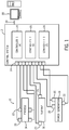
- FIG. 1 depicts one embodiment of an industrial system 10 (e.g., a power generation plant) coupled to an industrial control system 12.
- an industrial system 10 e.g., a power generation plant
- the techniques described herein may be adapted to other processes, plants, or equipment.
- the industrial system 10 includes a process 14, a turbine 16, and a power generation component 18.
- gasifiers may include other processes and components, such as gasifiers, a gas treatment system (e.g., acid gas removal), air separation units, compressors, gears, turbo-expanders, pumps, motors, generators, fans, blowers, agitators, mixers, centrifuges, pulp refiners, ball mills, crushers/pulverizers, extruders, pelletizers, cooling towers/heat exchanger fans, and the like.
- gas treatment system e.g., acid gas removal
- air separation units e.g., acid gas removal
- compressors gears
- turbo-expanders e.g., turbo-expanders
- pumps e.g., gears, turbo-expanders
- motors e.g., motors, generators, fans, blowers, agitators, mixers, centrifuges, pulp refiners, ball mills, crushers/pulverizers, extruders, pelletizers, cooling towers/heat exchanger fans,
- the process 14, turbine 16, and power generation component 18 may include any number of sensors 20 and actuators/motors 22. More specifically, the sensors 20 may provide information regarding process conditions. For example, the sensors may monitor temperature, pressure, speed, fluid flow rate, vibration, noise, exhaust emissions, power output, clearance, or any other suitable parameter.
- the actuators 22 may perform a mechanical action in response to an input signal. For example, the actuators 22 may control a fuel injection rate, a diluent or water injection rate, a coolant rate, a power output level, a speed, a flow rate, a clearance, and so forth. As depicted, the sensors 20 and actuators 22 are in communication with the control system 12 via input/outputs 24.
- the sensors 20 and actuators 22 may be in communication with controllers 26 (e.g., programmable logic controllers) to facilitate monitoring and control of the industrial system 10.
- controllers 26 e.g., programmable logic controllers
- the controllers 26 may be referred to as "physical controllers.”
- the controllers 26 may be a Mark VIeTM control or Mark VIeSTM control, made available by General Electric Company of Schenectady, New York. In some embodiments, only one controller 26 is used.
- three controllers are used (e.g., R, S, T core controllers) to provide a triple modular redundant (TMR) control system 12 having enhanced redundancy and failover capabilities.
- the TMR control system 12 may, for example, perform a task with the output determined by a voting of the three cores R, S, and T. In other embodiments, four or more cores may be used.
- control system 12 may be coupled to and communicate with one or more workstations 28, which may include desktop computers, laptop computers, or other suitable computing devices.
- the workstation 28 may enable an operator to perform various functions, such as monitoring the components of the control system 12 (e.g., controllers 26 and input/outputs 24), and simulating operation of the control system 12 and the industrial system 10.
- one or more workstation or other computing devices 28 may be included in a simulation system. That is, the simulation may include multiple computing devices 28 to provide for additional computational capabilities.
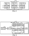
- a block diagram of one embodiment of a simulation system 30 is depicted in FIG. 2 . As depicted, the simulation system 30 includes multiple computing devices 28 (e.g., computing device 1, computing device 2, computing device N).
- each computing device 28 includes a processor 32 and memory 34.
- the processor 32 may be a multi-thread processor, a multi-core processor, multiple discrete processors, or any combination thereof.
- each of the computing devices 28, and more specifically the processor 32 and the memory 34 may enable an operator to perform functions, such as monitoring the components of the control system 12 (e.g., controllers 26 and input/outputs 24) and simulating operation of the control system 12 and the industrial system 10.
- each of the computing devices 28 may be communicatively coupled with the other computing devices 28 via a network 35, such Ethernet or the like.
- a network 35 such Ethernet or the like.
- other embodiments of the simulation system 30 utilize fewer computing devices 28, and in some embodiments may include only one computing device 28.
- the simulation system 30 may utilize virtual controllers and various models. More specifically, the simulation system 30 may simulate the operation of the control system 12 by executing one or more virtual controllers and the operation of the industrial system 10 by executing one or more component models and process models.
- the simulation system 30 includes a simulation executive 38, a monitor 40, virtual controllers 42, component models 44, process models 46, and shared memory 50.
- the simulation executive 38, monitor 40, virtual controllers 42, component models 44, and process models 46 may be executed by the processor 32 and stored by the memory 34 in the various computing devices 30 in the simulation system 30.
- the simulation executive 38 may be stored and executed on a first computing device while a monitor 40 and each of the virtual controllers 42 may be stored and executed on a second computing device.
- the shared memory 50 may utilize the physical memory 34 of the various computing devices 30.
- the desired configuration of the simulation system 30 may be adjusted based on various factors, such as the computing and storage capabilities of each computing device 28 and the computing and storage requirements of the virtual controllers 42 and models (e.g., component models 44 and process models 36). Accordingly, the simulation system 30 is described below as a whole without differentiating between the various physical computing devices 28.
- the simulation executive 38 is communicatively coupled to the monitor 40 to enable the simulation executive 38 and the monitor 40 to communicate.
- the simulation executive 38 may communicate instructions to the monitor 40, and more generally provide for simulation management and control.
- the monitor 40 is communicatively coupled to the virtual controllers 42, component models 44, and process models 46 to enable the monitor 40 to control the operation of the virtual controllers 42, component models 44, and process models 46.
- the virtual controllers 42, component models 44, and process models 46 may be coupled to the shared memory 50 to enable the virtual controllers 42, component models 44, and process models 46 to write to and read from the shared memory 50.
- the simulation executive 38 may be responsible for coordinating the execution of the simulation.
- the simulation executive 38 may maintain time coherency between the execution of simulation steps because the simulation steps may each have a different execution period.
- a component model 44 may have an execution step or period of 10 ms while a virtual controller may have an execution step or period of 40, 80, 120, or 160 ms.
- the simulation executive 38 may instruct specific virtual controllers 42 and models (e.g., component models 44 and process models 46) to perform a specific action.
- the simulation executive 38 may transmit an instruction identifying a virtual controller 42 and a control action, such as executing a control process step.
- the monitor 40 may be utilized as an intermediary.
- the monitor 40 may be a communication interface or system. More specifically, the monitor 40 may receive an instruction from the simulation executive 38 identifying which virtual controllers 42 or models are to perform a specific control action. Based on this instruction, the monitor 40 may instruct the identified virtual controllers 42 to perform the specified control action.
- the monitor 40 may be included on the same computing device 28 as a virtual controller 40 that the device 28 executes or instructs. Additionally, multiple monitors 40 may be utilized. For example, in some embodiments, one monitor 40 may be included on each computing device 28 that executes a virtual controller 42 or models 44, 46.
- the simulation executive 38 may provide for other actions, such as writing to the shared memory 50 and reading from the shared memory 50.
- the simulation executive 38 may be an Accelerated Real Time Engine Model Interactive Simulation (ARTEMIS), made available by General Electric Company of Schenectady, New York.
- ARTEMIS Accelerated Real Time Engine Model Interactive Simulation
- the simulation system 30 may include virtual controllers 42, component models 44, process models 46, or any combination thereof to enable simulation of the control system 12 or components of the control system 12. More specifically, the virtual controllers 42 may simulate the operation of a physical controller 26. Accordingly, each virtual controller 42 may include a controller model made up of a plurality of simulation steps or computer executable instructions. In some embodiments, the virtual controllers 42 may simulate a Mark VIeTM controller and/or a Mark VIeSTM controller with substantial fidelity.
- the simulation performed in a virtual controller 42 may be based at least in part on a captured state of one or more of the physical controllers 26, which may include process variables, state variable, diagnostic information, alarm information, event information, control commands, and the like.
- a virtual controller 42 receiving a captured state from a physical controller 26 is depicted in FIG. 4 .
- a captured state 52 of the physical controller 26 is stored in the memory 54 of the physical controller 26. The captured state 52 may then be communicated to the virtual controller 46.
- the captured state 52 may be captured either after one or more execution steps of the controller 26, at a desired time period (e.g., 1, 10, 100, 1000, or more milliseconds), by using debugging setpoints, or a combination thereof.
- the captured state may be restored in the virtual controller 46.
- the virtual controller 46 may choose a corresponding model state that matches the captured state 52.
- the virtual controller 46 may then execute a simulation step based at least in part on the corresponding model state.
- each component model 44 may model the operation of a component (e.g., turbine 16 or power generation 18), and each process model 46 may model the operation of process 14 in the industrial system 10, in which each model is made up of a plurality of simulation steps or executable instructions.
- These models may be based on first principles, such as physics based techniques (e.g., low cycle fatigue (LCF) life prediction models, computational fluid dynamics (CFD) models, finite element analysis (FEA) models, solid models (e.g., parametric and non-parametric modeling), and/or 3-dimension to 2-dimension FEA mapping models).
- the component models 44 may be Easy5 models, made available by MSC Software Corporation of Santa Ana, California.
- the process models 46 may be DynSim models, made available by Invensys PLC of London, United Kingdom.
- the shared memory 50 may be utilized to facilitate communication of data between each of the virtual controllers 42 and/or models. More specifically, inputs for each simulation step may be read from the shared memory 50 and outputs (e.g., results) of each simulation steps may be stored in the shared memory 50.
- the shared memory 50 stores the simulated status (e.g., operation parameters) of the control system 12 and/or the industrial system 10, updates the statuses after the execution of each simulation iteration, and may be accessible (e.g., read/write) by any of the simulation system 30 components.
- one iteration of the simulation may be performed, the results from that iteration may be stored in the shared memory 50 to update the statuses, and a subsequent iteration may be performed with the updated statuses.
- one iteration of the simulation is intended to describe the set of simulation steps that are executed based on the same status of the control system 12 and/or industrial system 10.
- the shared memory 50 may be a Reflective Memory system, made available by General Electric Company of Schenectady, New York.
- the simulation system 30 enables the simulation of the control system 12 and/or the industrial system 10.
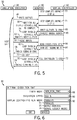
- One embodiment of the operation of the simulation system 30 is depicted in FIG. 5 . To simplify discussion, the simulation system 30 will be described in relation to simulation of the control system 10.
- FIG. 5 is an information flow diagram depicting an embodiment of information flows between the simulation executive 38, the monitor 40, and the virtual controller 42 of the simulation system 30.
- execution of a simulation iteration begins when the monitor 40 receives a write outputs instruction from the simulation executive 38 (process arrow 56).
- the monitor 40 may then wait for each of virtual controllers 42 to complete execution of a previous simulation step (process arrow 58).
- the monitor 40 instructs each of the virtual controllers 42 to write the results (e.g., outputs) of the previous simulation step into the shared memory 50 (process arrow 60).
- the monitor 40 returns a finished write outputs status to the simulation executive 38 (process arrow 62).
- the monitor 40 then receives a read inputs instruction from the simulation executive 38 (process arrow 64) and instructs each of the virtual controllers 42 to read inputs for a subsequent simulation step from the shared memory 50 (process arrow 66). After the inputs are read, the monitor 40 returns a finished read inputs status to the simulation executive 38 (process arrow 68). The monitor 40 then receives a do step instruction from the simulation executive 38 (process arrow 70) and instructs each of the virtual controllers 42 to begin execution of a simulation step in parallel (process arrow 72). Once the simulation step has been initiated in the virtual controllers 42, the monitor 40 returns a finished starting steps or completed status to the simulation executive 38 (process arrow 74).
- the monitor 40 may wait for each of the virtual controller 42 to complete execution of a previous simulation step (process arrow 58) by checking the execution status of the virtual controllers 42.
- the execution status of the virtual controllers 42 is intended to indicate whether the virtual controller 42 has or has not completed a simulation step. Additionally, the execution status may indicate the percent completed.
- the execution status of each of the virtual controller 42 may be maintained as an EventHandle that is stored as part of an array. Once a virtual controller 42 completes execution of a simulation step, a callback routine will set the EventHandle to indicate that the virtual controller 42 has completed the simulation step (process arrows 73 and 75). In some embodiments, not all of the virtual controllers 42 execute a simulation step during each iteration.
- the monitor 40 may wait for the virtual controllers 42 that will execute a simulation step in the next iteration of the simulation. Additionally, before the monitor 40 instructs the virtual controllers 42 to execute a simulation step, the EventHandle may be cleared to indicate that the virtual controllers 42 have not completed the subsequent simulation step.
- the monitor 40 may wait a specified time period for each of the virtual controllers 42 to complete. If one or more virtual controllers 42 has not completed within the specified time period, the monitor 40 may timeout and cease operation of the simulation. The monitor 40 may timeout because if one or more of the virtual controllers 42 has not completed the simulation step, subsequent simulation steps may be executed based on an incomplete status of the control system 12. As described above, some virtual controllers 42 may have varying execution periods. Accordingly, in some embodiments, the specified time period may be equal to the longest execution period of the virtual controllers 42.
- the monitor 40 may instructs each of the virtual controllers 42 to begin (e.g., initiate) execution of a simulation step in parallel (process arrow 72) by instructing each of the virtual controllers 42 to execute a simulation step in a parallel thread, processing core, processor, or a combination thereof.
- the monitor 40 may utilize a .NET delegate, thereby executing each simulation step on a thread from the .NET thread pool.
- execution of each simulation step is performed on a separate processing thread or core.
- execution of each simulation step may be allocated between a few threads or cores. In other words, execution of more than one simulation step may be allocated to each thread or core.
- the exact assignment of simulation steps to threads and/or cores may be customized based on the processing capabilities of the processors 32 and the processing requirements of the simulation steps.
- the monitor 40 sequentially instructs the virtual controllers 42 to begin operation (process arrow 76).
- the monitor 40 may instruct a first virtual controller to being execution, subsequently instruct a second virtual controller to begin execution, and so on.
- the monitor 40 may instruct the virtual controllers 42 to begin execution substantially simultaneously.
- the monitor 40 may broadcast an instruction to the virtual controllers 42 to being execution.
- each of the virtual controllers 42 may execute the simulation steps in parallel because, as described above, the execution is performed on a multiple parallel threads, cores, processors, or any combination thereof.
- the monitor 40 instructs the virtual controllers 42 to write to the shared memory 50 sequentially (process arrow 78). For example, the monitor 40 instructs a first virtual controller to write to the shared memory 50, receives a write complete status (process arrow 80) from the first virtual controller, subsequently instructs a second virtual controller to write to the shared memory 50, and so on. Similarly, the monitor 40 instructs the virtual controllers to read from the shared memory 50 sequentially (process arrow 82). For example, the monitor 40 instructs a first virtual controller to read from the shared memory 50, receives a read complete status (process arrow 84) from the first virtual controller, subsequently instructs a second virtual controller to read from the shared memory 50, and so on. Additionally or alternatively, the monitor 40 may substantially simultaneously instruct the virtual controller 42 to read or write from the shared memory 50, for example, by broadcasting the instruction.
- the monitor 40 returns a completed status to the simulation execution (process arrow 74). In other words, the monitor 40 returns a completed status without waiting for the virtual controllers 42 to complete execution of the simulation steps. As described above, completion is checked when the simulation executive 38 instructs the virtual controllers 42 to perform a subsequent control action, such as write outputs, via the monitor 40.
- the operation of the simulation system 30 may be adjusted to further improve the efficiency of the simulation system 30.
- the communication between the simulation executive 38 and the monitor 40 may be reduced by utilizing a monitor 40 with increased processing power. More specifically, the communication between the simulation executive 38 and the monitor 40 may be reduced to the monitor 40 receiving a do step instruction (process arrow 70) and returning a completed status (process arrow 72) once a simulation step is initiated in the virtual controllers 42.
- the monitor 40 may then instruct the virtual controllers 42 (e.g., write output 60, read input 66, and execute simulation step 72) in response to receiving the do step instruction.
- the simulation system 30 included three Dell T5500 dual quad-core computers (e.g., three computing devices 28), made availabe from Dell Inc. of Roud Rock, Texas.
- the virtual controllers 42 may be executed sequentially or in parallel.
- a graphical interface on the simulation system 30, such as the one depicted in FIG. 6 , may enable an operator to choose between sequential or parallel operation suitable for cycling (e.g., running a clock cycle) through the simulation. More specifically, FIG.
- the virtual controller run mode 92 includes a drop down menu that enables an operator to choose between a parallel mode 94, an asynchronous mode 96, and a serial (i.e., sequential) mode 98.
- a parallel mode 94 e.g., a parallel mode
- asynchronous mode 96 e.g., asynchronous mode
- serial (i.e., sequential) mode 98 i.e., sequential) mode
- Results 100 from benchmarking the Duke-Edwards IGCC plant when the sequential mode 98 is selected for execution of the virtual controllers 42 is depicted in a screen capture of the simulation executive 38 shown in FIG. 7 .
- the simulation results 100 includes a graphical representation of the simulation system 102, a simulation execution list 104 that describes the simulation steps that have been executed, and a settings window 106 that describes the settings of the simulation system 30.
- the simulation system 30 simulated operations of the plant up to 75.12% of real-time operations of the plant (arrow 102). Additionally, the processors 32 in the simulation system 30 were loaded to around 20% of total processing capabilities.
- Results 110 from benchmarking the Duke-Edwards IGCC plant when the parallel mode 92 is selected for execution of the virtual controllers 42 is depicted in a screen capture of the simulation executive depicted in FIG. 8 .
- the simulation system 30 simulated the operation of the plant up to 317.56% of real-time operation of the plant (arrow 112). Additionally, the processrs 32 in the simulation system 30 were loaded to around 80% of total processing capabilities. Accordingly, the simulation efficiency may be vastly improved by better utilizing the processing architecture of the processors 32.
- the simulation efficiency may be improved by better utilizing the processing capabilities of the simulation system to execute simulation steps in parallel. In some embodiments, this may include executing simulation steps in parallel on multiple threads, processing cores, or processors. Accordingly, the simulation speed of the simulation system 30 may also be improved, which enables operations, such as testing or validation, to also be completed more efficiently.
Description
- The subject matter disclosed herein relates generally to simulation systems, and more specifically, to simulation systems used to simulate operation of a control system useful in controlling plants, equipment, and processes.
- Control systems for processes, plants, and equipment, may include a wide variety of logic to configure how the control system monitors and controls the processes, plants and equipment. For example, a control system may include a controller designed to monitor and control the process, plant, and/or equipment. To improve operation of the control system, a simulation system, including virtual controllers, component models, process models, or any combination thereof, may be utilized to simulate the operation of the control system. Accordingly, it would be beneficial to improve the simulation logic of such a simulation system.
-
US 2013/191106 describes a system and method for operating a remote plant simulation system using a light application at the plant to collect relevant data and communicate it to a remote plant simulation. The remote plant simulation uses the relevant data, including data from the actual process, to create a process simulation and communicate the display data to the light application operating at the plant where it is displayed to a user. - The present invention resides in a method to simulate operation of a control system and/or an industrial system coupled to the control system, a computer program and a simulation system as defined in the appended claims.
- These and other features, aspects, and advantages of the present invention will become better understood when the following detailed description is read with reference to the accompanying drawings in which like characters represent like parts throughout the drawings, wherein:
-
FIG. 1 is a block diagram of an industrial plant including a control system, in accordance with an embodiment; -
FIG. 2 is a block diagram of a simulation system suitable for simulating the control system ofFIG. 1 , in accordance with an embodiment; -
FIG. 3 is an information flow diagram for the simulation system depicted inFIG. 2 , in accordance with an embodiment; -
FIG. 4 is a block diagram of a virtual controller receiving a captured state from a physical controller, in accordance with an embodiment; -
FIG. 5 is an information flow diagram for the simulation system depicted inFIG. 2 , in accordance with an embodiment; -
FIG. 6 is a settings display for the simulation system depicted inFIG. 2 , in accordance with an embodiment; -
FIG. 7 is a display illustrating operations of the simulation system depicted inFIG. 2 when a sequential mode is selected, in accordance with an embodiment; and -
FIG. 8 is a display illustration operations of the simulation system depicted inFIG. 2 when a parallel mode is selected, in accordance with an embodiment. - Generally, a control system includes various controllers (e.g., industrial controllers) suitable for monitoring and/or controlling processes (e.g., industrial processes), plants, and/or equipment. For example, a controller may monitor and control the operation of other components, such as machinery, and processes in an industrial system, such as a gas turbine system, a gasification system, a steam turbine system, a wind turbine system, a water turbine system, a power generation system, integrated gasification combined cycle system, or any combination thereof.
- The operation of the control system, processes, plants and/or equipment may be simulated by a simulation system running on a workstation or other computing device. In some embodiments, the simulation may be progressed (e.g., executed up to a discrete number of desired steps) to enable analysis of part of a process, plant or equipment in a step-by-step manner. For example, a control action or sequence of actions to be performed by a physical controller may first be simulated in a virtual controller. Accordingly, the simulation system may include various models, which each includes a plurality of simulation steps, suitable for simulating the operation of physical controllers, components, and processes. In some embodiments, the simulation system may execute simulation steps sequentially. For example, the simulation system may execute a first simulation step, wait for the first simulation step to complete, execute a second simulation step, wait for the second simulation to complete, and so on. However, it would be beneficial to improve the simulation efficiency of a simulation system by more efficiently utilizing advancements in processing architecture, such as multi-threaded and multi-core processors.
- Accordingly, the present disclosure includes, in one embodiment, a non-transitory tangible computer-readable medium including instructions executable by a processor in a simulation system to perform a simulation. The instructions may include to wait for a plurality of virtual controllers to complete a previous simulation step, write a result of the previous simulation step from each of the plurality of virtual controllers to a shared memory, read an input from the memory to each of the plurality of virtual controllers, initiate a simulation step on each of the plurality of virtual controllers, and upon initiation of the simulation step in each of the plurality of virtual controllers, indicate completion of the simulation, in which the plurality of virtual controllers include a controller model having a plurality of simulation steps and the instructions are configured to be executed by the processor in parallel. In other words, instead of executing simulation steps sequentially, the simulation steps may be executed in parallel to improve the simulation efficiency of the simulation system. In some embodiments, this may enable the simulation system to simulate operation substantially faster than real-time operation. Several novel techniques are described below, which may improve time of simulation and/or memory/processing constraints when simulating, for example, parallel branches related to physical controllers. As can be appreciated, this may also improve the efficiency of testing, validation of components and the like.
- By way of introduction,
FIG. 1 depicts one embodiment of an industrial system 10 (e.g., a power generation plant) coupled to anindustrial control system 12. Although anindustrial system 10 is described, the techniques described herein may be adapted to other processes, plants, or equipment. As depicted, theindustrial system 10 includes aprocess 14, aturbine 16, and apower generation component 18. Other embodiments of theindustrial system 10 may include other processes and components, such as gasifiers, a gas treatment system (e.g., acid gas removal), air separation units, compressors, gears, turbo-expanders, pumps, motors, generators, fans, blowers, agitators, mixers, centrifuges, pulp refiners, ball mills, crushers/pulverizers, extruders, pelletizers, cooling towers/heat exchanger fans, and the like. - Additionally, in the depicted embodiment, the
process 14,turbine 16, andpower generation component 18 may include any number ofsensors 20 and actuators/motors 22. More specifically, thesensors 20 may provide information regarding process conditions. For example, the sensors may monitor temperature, pressure, speed, fluid flow rate, vibration, noise, exhaust emissions, power output, clearance, or any other suitable parameter. Theactuators 22 may perform a mechanical action in response to an input signal. For example, theactuators 22 may control a fuel injection rate, a diluent or water injection rate, a coolant rate, a power output level, a speed, a flow rate, a clearance, and so forth. As depicted, thesensors 20 andactuators 22 are in communication with thecontrol system 12 via input/outputs 24. More specifically, thesensors 20 andactuators 22 may be in communication with controllers 26 (e.g., programmable logic controllers) to facilitate monitoring and control of theindustrial system 10. As used herein, thecontrollers 26 may be referred to as "physical controllers." In some embodiments, thecontrollers 26 may be a Mark VIe™ control or Mark VIeS™ control, made available by General Electric Company of Schenectady, New York. In some embodiments, only onecontroller 26 is used. In another embodiments, three controllers are used (e.g., R, S, T core controllers) to provide a triple modular redundant (TMR)control system 12 having enhanced redundancy and failover capabilities. TheTMR control system 12 may, for example, perform a task with the output determined by a voting of the three cores R, S, and T. In other embodiments, four or more cores may be used. - Additionally, the
control system 12 may be coupled to and communicate with one ormore workstations 28, which may include desktop computers, laptop computers, or other suitable computing devices. Theworkstation 28 may enable an operator to perform various functions, such as monitoring the components of the control system 12 (e.g.,controllers 26 and input/outputs 24), and simulating operation of thecontrol system 12 and theindustrial system 10. More specifically, to facilitate simulation, one or more workstation orother computing devices 28 may be included in a simulation system. That is, the simulation may includemultiple computing devices 28 to provide for additional computational capabilities. A block diagram of one embodiment of asimulation system 30 is depicted inFIG. 2 . As depicted, thesimulation system 30 includes multiple computing devices 28 (e.g.,computing device 1,computing device 2, computing device N). Furthermore, eachcomputing device 28 includes aprocessor 32 andmemory 34. In some embodiments, theprocessor 32 may be a multi-thread processor, a multi-core processor, multiple discrete processors, or any combination thereof. Accordingly, each of thecomputing devices 28, and more specifically theprocessor 32 and thememory 34, may enable an operator to perform functions, such as monitoring the components of the control system 12 (e.g.,controllers 26 and input/outputs 24) and simulating operation of thecontrol system 12 and theindustrial system 10. Additionally, each of thecomputing devices 28 may be communicatively coupled with theother computing devices 28 via anetwork 35, such Ethernet or the like. As can be appreciated, by utilizing the techniques described herein, other embodiments of thesimulation system 30 utilizefewer computing devices 28, and in some embodiments may include only onecomputing device 28. - To simulate operation of the
control system 12 and theindustrial system 10, thesimulation system 30 may utilize virtual controllers and various models. More specifically, thesimulation system 30 may simulate the operation of thecontrol system 12 by executing one or more virtual controllers and the operation of theindustrial system 10 by executing one or more component models and process models. One embodiment of the information flow within thesimulation system 30 is depicted inFIG. 3 . As depicted, thesimulation system 30 includes asimulation executive 38, amonitor 40,virtual controllers 42,component models 44,process models 46, and sharedmemory 50. In some embodiments, thesimulation executive 38,monitor 40,virtual controllers 42,component models 44, andprocess models 46 may be executed by theprocessor 32 and stored by thememory 34 in thevarious computing devices 30 in thesimulation system 30. For example, thesimulation executive 38 may be stored and executed on a first computing device while amonitor 40 and each of thevirtual controllers 42 may be stored and executed on a second computing device. Additionally, the sharedmemory 50 may utilize thephysical memory 34 of thevarious computing devices 30. The desired configuration of thesimulation system 30 may be adjusted based on various factors, such as the computing and storage capabilities of eachcomputing device 28 and the computing and storage requirements of thevirtual controllers 42 and models (e.g.,component models 44 and process models 36). Accordingly, thesimulation system 30 is described below as a whole without differentiating between the variousphysical computing devices 28. - As depicted, the
simulation executive 38 is communicatively coupled to themonitor 40 to enable thesimulation executive 38 and themonitor 40 to communicate. For example, thesimulation executive 38 may communicate instructions to themonitor 40, and more generally provide for simulation management and control. Additionally, themonitor 40 is communicatively coupled to thevirtual controllers 42,component models 44, andprocess models 46 to enable themonitor 40 to control the operation of thevirtual controllers 42,component models 44, andprocess models 46. Furthermore, thevirtual controllers 42,component models 44, andprocess models 46 may be coupled to the sharedmemory 50 to enable thevirtual controllers 42,component models 44, andprocess models 46 to write to and read from the sharedmemory 50. - More specifically, the
simulation executive 38 may be responsible for coordinating the execution of the simulation. In other words, thesimulation executive 38 may maintain time coherency between the execution of simulation steps because the simulation steps may each have a different execution period. For example, acomponent model 44 may have an execution step or period of 10 ms while a virtual controller may have an execution step or period of 40, 80, 120, or 160 ms. Accordingly, thesimulation executive 38 may instruct specificvirtual controllers 42 and models (e.g.,component models 44 and process models 46) to perform a specific action. For example, thesimulation executive 38 may transmit an instruction identifying avirtual controller 42 and a control action, such as executing a control process step. To facilitate the communication of the instructions between thesimulation executive 38 and thevirtual controller 42 or various models, themonitor 40 may be utilized as an intermediary. In other words, themonitor 40 may be a communication interface or system. More specifically, themonitor 40 may receive an instruction from thesimulation executive 38 identifying whichvirtual controllers 42 or models are to perform a specific control action. Based on this instruction, themonitor 40 may instruct the identifiedvirtual controllers 42 to perform the specified control action. Accordingly, in some embodiments, themonitor 40 may be included on thesame computing device 28 as avirtual controller 40 that thedevice 28 executes or instructs. Additionally,multiple monitors 40 may be utilized. For example, in some embodiments, onemonitor 40 may be included on eachcomputing device 28 that executes avirtual controller 42 ormodels simulation executive 38 may provide for other actions, such as writing to the sharedmemory 50 and reading from the sharedmemory 50. In some embodiments, thesimulation executive 38 may be an Accelerated Real Time Engine Model Interactive Simulation (ARTEMIS), made available by General Electric Company of Schenectady, New York. - As described above, the
simulation system 30 may includevirtual controllers 42,component models 44,process models 46, or any combination thereof to enable simulation of thecontrol system 12 or components of thecontrol system 12. More specifically, thevirtual controllers 42 may simulate the operation of aphysical controller 26. Accordingly, eachvirtual controller 42 may include a controller model made up of a plurality of simulation steps or computer executable instructions. In some embodiments, thevirtual controllers 42 may simulate a Mark VIe™ controller and/or a Mark VIeS™ controller with substantial fidelity. - In some embodiments, the simulation performed in a
virtual controller 42 may be based at least in part on a captured state of one or more of thephysical controllers 26, which may include process variables, state variable, diagnostic information, alarm information, event information, control commands, and the like. One embodiment of avirtual controller 42 receiving a captured state from aphysical controller 26 is depicted inFIG. 4 . As depicted, a capturedstate 52 of thephysical controller 26 is stored in thememory 54 of thephysical controller 26. The capturedstate 52 may then be communicated to thevirtual controller 46. For example, the capturedstate 52 may be captured either after one or more execution steps of thecontroller 26, at a desired time period (e.g., 1, 10, 100, 1000, or more milliseconds), by using debugging setpoints, or a combination thereof. After receiving the capturedstate 52, the captured state may be restored in thevirtual controller 46. For example, thevirtual controller 46 may choose a corresponding model state that matches the capturedstate 52. Thevirtual controller 46 may then execute a simulation step based at least in part on the corresponding model state. - Similarly, each
component model 44 may model the operation of a component (e.g.,turbine 16 or power generation 18), and eachprocess model 46 may model the operation ofprocess 14 in theindustrial system 10, in which each model is made up of a plurality of simulation steps or executable instructions. These models may be based on first principles, such as physics based techniques (e.g., low cycle fatigue (LCF) life prediction models, computational fluid dynamics (CFD) models, finite element analysis (FEA) models, solid models (e.g., parametric and non-parametric modeling), and/or 3-dimension to 2-dimension FEA mapping models). Accordingly, in some embodiments, thecomponent models 44 may be Easy5 models, made available by MSC Software Corporation of Santa Ana, California. Additionally, in some embodiments, theprocess models 46 may be DynSim models, made available by Invensys PLC of London, United Kingdom. - Furthermore, the shared
memory 50 may be utilized to facilitate communication of data between each of thevirtual controllers 42 and/or models. More specifically, inputs for each simulation step may be read from the sharedmemory 50 and outputs (e.g., results) of each simulation steps may be stored in the sharedmemory 50. In other words, the sharedmemory 50 stores the simulated status (e.g., operation parameters) of thecontrol system 12 and/or theindustrial system 10, updates the statuses after the execution of each simulation iteration, and may be accessible (e.g., read/write) by any of thesimulation system 30 components. For example, one iteration of the simulation may be performed, the results from that iteration may be stored in the sharedmemory 50 to update the statuses, and a subsequent iteration may be performed with the updated statuses. As used herein, one iteration of the simulation is intended to describe the set of simulation steps that are executed based on the same status of thecontrol system 12 and/orindustrial system 10. In some embodiments, the sharedmemory 50 may be a Reflective Memory system, made available by General Electric Company of Schenectady, New York. - As described above, the
simulation system 30 enables the simulation of thecontrol system 12 and/or theindustrial system 10. One embodiment of the operation of thesimulation system 30 is depicted inFIG. 5 . To simplify discussion, thesimulation system 30 will be described in relation to simulation of thecontrol system 10. - However, it can be appreciated that the techniques described below may be applied to simulation of the
industrial system 10 or the simulation of any process, equipment, or plant that utilizes simulation models made up of a plurality of simulation steps. -
FIG. 5 is an information flow diagram depicting an embodiment of information flows between thesimulation executive 38, themonitor 40, and thevirtual controller 42 of thesimulation system 30. As depicted, execution of a simulation iteration begins when themonitor 40 receives a write outputs instruction from the simulation executive 38 (process arrow 56). Themonitor 40 may then wait for each ofvirtual controllers 42 to complete execution of a previous simulation step (process arrow 58). Once thevirtual controllers 42 have completed execution, themonitor 40 instructs each of thevirtual controllers 42 to write the results (e.g., outputs) of the previous simulation step into the shared memory 50 (process arrow 60). After the results are stored, themonitor 40 returns a finished write outputs status to the simulation executive 38 (process arrow 62). Themonitor 40 then receives a read inputs instruction from the simulation executive 38 (process arrow 64) and instructs each of thevirtual controllers 42 to read inputs for a subsequent simulation step from the shared memory 50 (process arrow 66). After the inputs are read, themonitor 40 returns a finished read inputs status to the simulation executive 38 (process arrow 68). Themonitor 40 then receives a do step instruction from the simulation executive 38 (process arrow 70) and instructs each of thevirtual controllers 42 to begin execution of a simulation step in parallel (process arrow 72). Once the simulation step has been initiated in thevirtual controllers 42, themonitor 40 returns a finished starting steps or completed status to the simulation executive 38 (process arrow 74). - More specifically, the
monitor 40 may wait for each of thevirtual controller 42 to complete execution of a previous simulation step (process arrow 58) by checking the execution status of thevirtual controllers 42. As used herein the execution status of thevirtual controllers 42 is intended to indicate whether thevirtual controller 42 has or has not completed a simulation step. Additionally, the execution status may indicate the percent completed. In some embodiments, the execution status of each of thevirtual controller 42 may be maintained as an EventHandle that is stored as part of an array. Once avirtual controller 42 completes execution of a simulation step, a callback routine will set the EventHandle to indicate that thevirtual controller 42 has completed the simulation step (process arrows 73 and 75). In some embodiments, not all of thevirtual controllers 42 execute a simulation step during each iteration. Accordingly, themonitor 40 may wait for thevirtual controllers 42 that will execute a simulation step in the next iteration of the simulation. Additionally, before themonitor 40 instructs thevirtual controllers 42 to execute a simulation step, the EventHandle may be cleared to indicate that thevirtual controllers 42 have not completed the subsequent simulation step. - Furthermore, the
monitor 40 may wait a specified time period for each of thevirtual controllers 42 to complete. If one or morevirtual controllers 42 has not completed within the specified time period, themonitor 40 may timeout and cease operation of the simulation. Themonitor 40 may timeout because if one or more of thevirtual controllers 42 has not completed the simulation step, subsequent simulation steps may be executed based on an incomplete status of thecontrol system 12. As described above, somevirtual controllers 42 may have varying execution periods. Accordingly, in some embodiments, the specified time period may be equal to the longest execution period of thevirtual controllers 42. - The
monitor 40 may instructs each of thevirtual controllers 42 to begin (e.g., initiate) execution of a simulation step in parallel (process arrow 72) by instructing each of thevirtual controllers 42 to execute a simulation step in a parallel thread, processing core, processor, or a combination thereof. For example, themonitor 40 may utilize a .NET delegate, thereby executing each simulation step on a thread from the .NET thread pool. In some embodiments, execution of each simulation step is performed on a separate processing thread or core. Additionally or alternatively, execution of each simulation step may be allocated between a few threads or cores. In other words, execution of more than one simulation step may be allocated to each thread or core. The exact assignment of simulation steps to threads and/or cores may be customized based on the processing capabilities of theprocessors 32 and the processing requirements of the simulation steps. - Additionally, in the depicted embodiment, the
monitor 40 sequentially instructs thevirtual controllers 42 to begin operation (process arrow 76). For example, themonitor 40 may instruct a first virtual controller to being execution, subsequently instruct a second virtual controller to begin execution, and so on. Additionally or alternatively, themonitor 40 may instruct thevirtual controllers 42 to begin execution substantially simultaneously. For example, themonitor 40 may broadcast an instruction to thevirtual controllers 42 to being execution. In either embodiment, each of thevirtual controllers 42 may execute the simulation steps in parallel because, as described above, the execution is performed on a multiple parallel threads, cores, processors, or any combination thereof. - Furthermore, in the depicted embodiment, the
monitor 40 instructs thevirtual controllers 42 to write to the sharedmemory 50 sequentially (process arrow 78). For example, themonitor 40 instructs a first virtual controller to write to the sharedmemory 50, receives a write complete status (process arrow 80) from the first virtual controller, subsequently instructs a second virtual controller to write to the sharedmemory 50, and so on. Similarly, themonitor 40 instructs the virtual controllers to read from the sharedmemory 50 sequentially (process arrow 82). For example, themonitor 40 instructs a first virtual controller to read from the sharedmemory 50, receives a read complete status (process arrow 84) from the first virtual controller, subsequently instructs a second virtual controller to read from the sharedmemory 50, and so on. Additionally or alternatively, themonitor 40 may substantially simultaneously instruct thevirtual controller 42 to read or write from the sharedmemory 50, for example, by broadcasting the instruction. - Finally, once the simulation step has been initiated in the
virtual controllers 42, themonitor 40 returns a completed status to the simulation execution (process arrow 74). In other words, themonitor 40 returns a completed status without waiting for thevirtual controllers 42 to complete execution of the simulation steps. As described above, completion is checked when thesimulation executive 38 instructs thevirtual controllers 42 to perform a subsequent control action, such as write outputs, via themonitor 40. - In other embodiments, the operation of the
simulation system 30 may be adjusted to further improve the efficiency of thesimulation system 30. For example, the communication between thesimulation executive 38 and themonitor 40 may be reduced by utilizing amonitor 40 with increased processing power. More specifically, the communication between thesimulation executive 38 and themonitor 40 may be reduced to themonitor 40 receiving a do step instruction (process arrow 70) and returning a completed status (process arrow 72) once a simulation step is initiated in thevirtual controllers 42. Themonitor 40 may then instruct the virtual controllers 42 (e.g., write output 60, readinput 66, and execute simulation step 72) in response to receiving the do step instruction. - In benchmarking the above described techniques, the techniques were implemented in a simulation of a Duke-Edwards integrated gasification combined cycle (IGCC) plant located in Knox County, Indiana. The
simulation system 30 included three Dell T5500 dual quad-core computers (e.g., three computing devices 28), made availabe from Dell Inc. of Roud Rock, Texas. As described above, thevirtual controllers 42 may be executed sequentially or in parallel. Accordingly, a graphical interface on thesimulation system 30, such as the one depicted inFIG. 6 , may enable an operator to choose between sequential or parallel operation suitable for cycling (e.g., running a clock cycle) through the simulation. More specifically,FIG. 6 depictes an embodiment of a display (e.g., settings window 86) that enables an operator to select a timer mode 88, asimulation speed 90, and a virtualcontroller run mode 92. As depicted, the virtualcontroller run mode 92 includes a drop down menu that enables an operator to choose between aparallel mode 94, anasynchronous mode 96, and a serial (i.e., sequential)mode 98. Thus, an operator may easily switch between each of the three simulation modes by selecting a different simulation mode in the virtual controllerrun mode menu 92. -
Results 100 from benchmarking the Duke-Edwards IGCC plant when thesequential mode 98 is selected for execution of thevirtual controllers 42 is depicted in a screen capture of thesimulation executive 38 shown inFIG. 7 . As depicted, the simulation results 100 includes a graphical representation of thesimulation system 102, asimulation execution list 104 that describes the simulation steps that have been executed, and asettings window 106 that describes the settings of thesimulation system 30. In operation, thesimulation system 30 simulated operations of the plant up to 75.12% of real-time operations of the plant (arrow 102). Additionally, theprocessors 32 in thesimulation system 30 were loaded to around 20% of total processing capabilities. -
Results 110 from benchmarking the Duke-Edwards IGCC plant when theparallel mode 92 is selected for execution of thevirtual controllers 42 is depicted in a screen capture of the simulation executive depicted inFIG. 8 . In operation, thesimulation system 30 simulated the operation of the plant up to 317.56% of real-time operation of the plant (arrow 112). Additionally, theprocessrs 32 in thesimulation system 30 were loaded to around 80% of total processing capabilities. Accordingly, the simulation efficiency may be vastly improved by better utilizing the processing architecture of theprocessors 32. - Technical effects of the present disclosure include improving the simulation efficiency of a
simulation system 30. More specifically, the simulation efficiency may be improved by better utilizing the processing capabilities of the simulation system to execute simulation steps in parallel. In some embodiments, this may include executing simulation steps in parallel on multiple threads, processing cores, or processors. Accordingly, the simulation speed of thesimulation system 30 may also be improved, which enables operations, such as testing or validation, to also be completed more efficiently. - This written description uses examples to disclose the invention, including the best mode, and also to enable any person skilled in the art to practice the invention, including making and using any devices or systems and performing any incorporated methods. The patentable scope of the invention is defined by the claims.
Claims (14)
- A method for simulating operation of a control system (12) and/or an industrial system (10) coupled to the control system (12) in a simulation system (30), the control system (12) comprising one or more physical controllers (26) to facilitate monitoring and control of the industrial system (10), the method comprising:receiving an instruction from a simulation executive (38) to execute a new simulation step on a plurality of virtual controllers (42) of the simulation system (30), wherein each of the plurality of virtual controllers (42) is configured to simulate the operation of one or more of the physical controllers (26) and includes a controller model comprising a plurality of simulation steps;determining a subset of virtual controllers (42) from the plurality of virtual controllers (42) to use to execute the new simulation step;waiting (58) for each of the subset of virtual controllers (42) to complete a previous simulation step;instructing (60) each of the subset of virtual controllers (42) to write a result of the previous simulation step to a shared memory (50);instructing (66) each of the subset of virtual controllers (42) to read an input from the shared memory (50);instructing (72) each of the subset of virtual controllers (42) to begin execution of the new simulation step to enable each of the virtual controllers (42) to execute the simulation step in parallel, andtransmitting (74) a complete status to the simulation executive (38) once the new simulation step has been initiated in each of the subset of virtual controllers (42) without waiting for the plurality of virtual controllers (42) to complete the simulation step.
- The method of claim 1, wherein instructing (72) each of the subset of virtual controllers (42) to begin execution of the simulation step comprises instructing each of the subset of virtual controllers (42) to begin execution of the simulation step on a separate computing thread.
- The method of claim 1 or claim 2, wherein instructing (72) each of the subset of virtual controllers (42) to begin execution of the simulation step comprises instructing each of the subset of virtual controllers (42) to begin execution of the simulation step on a separate processing core.
- The method of any of claims 1 to 3, wherein instructing (60) each of the subset of virtual controllers (42) to write a result of the previous simulation step to a shared memory (50) comprises sequentially instructing each of the subset of virtual controllers (42) and waiting for each of the subset of virtual controllers (42) to complete writing before instructing a subsequent virtual controller (42).
- The method of any preceding claim, wherein instructing (66) each of the subset of virtual controllers (42) to read an input from the shared memory (50) comprises sequentially instructing each of the subset of virtual controllers (42) and waiting for each of the subset of virtual controllers (42) to complete reading before instructing a subsequent virtual controller (42).
- The method of any preceding claim, further comprising storing the execution status of each of the plurality of virtual controllers (42), wherein waiting (58) for the subset of virtual controllers (42) to complete the previous simulation step comprises checking the status of each of the subset of virtual controllers (42).
- The method of any preceding claim, wherein initiating the new simulation step on each of the subset of virtual controllers (42) comprises initiating the simulation step on each of the subset of virtual controllers sequentially or simultaneously.
- The method of claim 7, further comprising performing a timeout if one of the subset of virtual controllers (42) does not complete the previous simulation step within a specified time period.
- A computer program comprising computer program code means adapted to perform the steps of the method of any of claims 1 to 8, when executed by one or more computer processors in a simulation system.
- The computer program of claim 9, embodied on a computer-readable medium.
- A simulation system (30) configured to simulate operation of a control system (12) and/or an industrial system (10) coupled to the control system (12), the control system (12) comprising one or more physical controllers (26) to facilitate monitoring and control of the industrial system (10), the system comprising:
a processor (32) configured to execute:a simulation executive (38) configured to coordinate operation of the simulation system (30);a plurality of virtual controllers (42), wherein each of the plurality of virtual controllers (42) is configured to simulate the operation of one or more of the physical controllers (26) and includes a controller model comprising a plurality of simulation steps, wherein each of the plurality of virtual controllers (42) is further configured to execute a simulation step in parallel with the other of the plurality of virtual controllers (42);a communication interface (40) communicatively coupled to the simulation executive (38) and the plurality of virtual controllers (42), wherein the communication interface (40) is configured to:receive an instruction from the simulation executive (38) to execute a new simulation step, wherein the simulation executive (38) or the communication interface (40) determines a subset of virtual controllers (42) from the plurality of virtual controllers (42) to use to execute the new simulation step;wait for each of the subset of virtual controllers (42) to complete a previous simulation step;instruct each of the subset of virtual controllers (42) to write a result of the previous simulation step to a shared memory (50);instruct (66) each of the subset of virtual controllers to read an input from the shared memory (50);instruct each of the subset of virtual controllers (42) to begin execution of a new simulation step in parallel; andtransmit a complete status to the simulation executive (38) once the new simulation step has been initiated in each of the subset of virtual controllers (42) without waiting for the plurality of virtual controllers (42) to complete the simulation step. - The simulation system of claim 11, wherein the processor (32) comprises a multi-threaded processor and/or a multi-core processor, wherein each of the plurality of virtual controllers (42) is configured to:execute the simulation step on a separate computing thread on the multi-threaded processor, and/orexecute the simulation step on a separate process core on the multi-core processor.
- The simulation system of claim 11 or 12, comprising a shared memory (50) communicatively coupled to the processor (32).
- The simulation system of any one of claims 11 to 13, wherein the simulation system (30) is configured to simulate operation of a gas turbine system, a gasification system, a steam turbine system, a wind turbine system, a water turbine system, a power generation system, integrated gasification combined cycle system, or any combination thereof.
Applications Claiming Priority (1)
| Application Number | Priority Date | Filing Date | Title |
|---|---|---|---|
| US14/028,368 US9501300B2 (en) | 2013-09-16 | 2013-09-16 | Control system simulation system and method |
Publications (2)
| Publication Number | Publication Date |
|---|---|
| EP2849006A1 EP2849006A1 (en) | 2015-03-18 |
| EP2849006B1 true EP2849006B1 (en) | 2019-09-11 |
Family
ID=51518688
Family Applications (1)
| Application Number | Title | Priority Date | Filing Date |
|---|---|---|---|
| EP14184541.2A Active EP2849006B1 (en) | 2013-09-16 | 2014-09-12 | Control system simulation system and method |
Country Status (4)
| Country | Link |
|---|---|
| US (1) | US9501300B2 (en) |
| EP (1) | EP2849006B1 (en) |
| JP (1) | JP6514465B2 (en) |
| CN (1) | CN104460360B (en) |
Families Citing this family (17)
| Publication number | Priority date | Publication date | Assignee | Title |
|---|---|---|---|---|
| EP2784704A1 (en) * | 2013-03-26 | 2014-10-01 | Fujitsu Limited | Multi-component computational fluid dynamics simulations |
| EP3141970B1 (en) * | 2015-09-09 | 2017-11-15 | Siemens Aktiengesellschaft | Decentralized periphery |
| CN106647323B (en) * | 2015-10-30 | 2021-04-09 | 北京北方华创微电子装备有限公司 | Equipment simulation operation control method and device |
| US10692113B2 (en) * | 2016-06-21 | 2020-06-23 | Htc Corporation | Method for providing customized information through advertising in simulation environment, and associated simulation system |
| US10579536B2 (en) * | 2016-08-09 | 2020-03-03 | Arizona Board Of Regents On Behalf Of Arizona State University | Multi-mode radiation hardened multi-core microprocessors |
| US20180135456A1 (en) * | 2016-11-17 | 2018-05-17 | General Electric Company | Modeling to detect gas turbine anomalies |
| CN106774277B (en) * | 2017-01-17 | 2019-03-08 | 爱普(福建)科技有限公司 | A kind of data sharing method between more Virtual Controllers |
| US10564993B2 (en) * | 2017-11-07 | 2020-02-18 | General Electric Company | Contextual digital twin runtime environment |
| CN109976186A (en) * | 2017-12-27 | 2019-07-05 | 江苏金风科技有限公司 | Emulation test system |
| FR3078176B1 (en) * | 2018-02-19 | 2020-02-28 | IFP Energies Nouvelles | SYSTEM AND METHOD FOR PREDICTING A PHYSICAL AND / OR CHEMICAL PHENOMENON USING A SHARED MEMORY SEGMENT |
| CN112204482A (en) * | 2018-05-31 | 2021-01-08 | 西门子股份公司 | Redundant hot standby control system, method, control device and computer readable storage medium |
| CN109240128A (en) * | 2018-11-26 | 2019-01-18 | 山东大学 | A kind of new energy supply of cooling, heating and electrical powers real-time emulation system and method |
| CN111177893B (en) * | 2019-12-11 | 2023-05-02 | 中电普信(北京)科技发展有限公司 | Parallel discrete simulation event driving method and device based on multithreading |
| CN111273541B (en) * | 2020-04-03 | 2023-05-02 | 四川谊田集群科技有限公司 | Control system and method of virtual redundant controller based on communication |
| US11531563B2 (en) * | 2020-06-26 | 2022-12-20 | Intel Corporation | Technology for optimizing hybrid processor utilization |
| CN112610419B (en) * | 2020-12-16 | 2022-04-29 | 南京工程学院 | Hydraulic wind turbine generator set based on PLC and MSC II control |
| CN114779666B (en) * | 2022-06-20 | 2022-09-16 | 西安羚控电子科技有限公司 | Simulation verification system and method |
Family Cites Families (24)
| Publication number | Priority date | Publication date | Assignee | Title |
|---|---|---|---|---|
| US6134514A (en) | 1998-06-25 | 2000-10-17 | Itt Manufacturing Enterprises, Inc. | Large-scale network simulation method and apparatus |
| US20030005068A1 (en) * | 2000-12-28 | 2003-01-02 | Nickel Ronald H. | System and method for creating a virtual supercomputer using computers working collaboratively in parallel and uses for the same |
| US6671659B2 (en) | 2001-06-27 | 2003-12-30 | General Electric Co. | System and method for monitoring controller diagnostics |
| JP2003323203A (en) * | 2002-04-30 | 2003-11-14 | Mitsubishi Electric Corp | Off-line test device, and its method |
| US7146231B2 (en) * | 2002-10-22 | 2006-12-05 | Fisher-Rosemount Systems, Inc.. | Smart process modules and objects in process plants |
| JP3654360B2 (en) * | 2002-12-02 | 2005-06-02 | ソニー株式会社 | Control system and method, information processing apparatus and method, information processing terminal and method, recording medium, and program |
| KR100487439B1 (en) * | 2002-12-31 | 2005-05-03 | 엘지.필립스 엘시디 주식회사 | Circuit and method for bi-directional driving plat display device |
| CN100343803C (en) * | 2004-07-26 | 2007-10-17 | 国际商业机器公司 | Method and syste mfor transplanting prsonalized computation environment from source platform to target platform |
| JP5059017B2 (en) * | 2006-09-27 | 2012-10-24 | 富士通テン株式会社 | Simulation device |
| US8056062B2 (en) | 2007-05-14 | 2011-11-08 | General Electric Company | Methods and systems for converting application code in turbine control systems |
| JP2009037329A (en) * | 2007-07-31 | 2009-02-19 | Mitsubishi Electric Corp | Plc system simulator |
| US20090089031A1 (en) * | 2007-09-28 | 2009-04-02 | Rockwell Automation Technologies, Inc. | Integrated simulation of controllers and devices |
| US20090271169A1 (en) * | 2008-04-29 | 2009-10-29 | General Electric Company | Training Simulators for Engineering Projects |
| FR2939922B1 (en) | 2008-12-16 | 2011-03-04 | Bull Sas | PHYSICAL MANAGER OF SYNCHRONIZATION BARRIER BETWEEN MULTIPLE PROCESSES |
| WO2011023203A1 (en) | 2009-08-24 | 2011-03-03 | Abb Technology Ag | Improved execution of real time applications with an automation controller |
| WO2011023204A1 (en) | 2009-08-24 | 2011-03-03 | Abb Research Ltd. | Simulation of distributed virtual control systems |
| US9606531B2 (en) | 2009-12-01 | 2017-03-28 | Emerson Process Management Power & Water Solutions, Inc. | Decentralized industrial process simulation system |
| JP4817084B2 (en) * | 2010-03-30 | 2011-11-16 | 株式会社安川電機 | Motor drive system and motor control device |
| DE102010015314B4 (en) * | 2010-04-17 | 2012-12-13 | Audi Ag | Method for operating drive control devices in a motor vehicle and motor vehicle |
| US9110690B2 (en) | 2010-04-28 | 2015-08-18 | General Electric Company | Systems, methods, and apparatus for deploying application code change configurations for multiple target controllers |
| US10037443B2 (en) * | 2011-03-07 | 2018-07-31 | Rockwell Automation Technologies, Inc. | Industrial simulation using redirected I/O module configurations |
| US9529348B2 (en) * | 2012-01-24 | 2016-12-27 | Emerson Process Management Power & Water Solutions, Inc. | Method and apparatus for deploying industrial plant simulators using cloud computing technologies |
| JP5726776B2 (en) * | 2012-02-06 | 2015-06-03 | 株式会社東芝 | Simulator software replacement apparatus, method, and program |
| US9261869B2 (en) * | 2012-02-13 | 2016-02-16 | Emerson Process Management Power & Water Solutions, Inc. | Hybrid sequential and simultaneous process simulation system |
-
2013
- 2013-09-16 US US14/028,368 patent/US9501300B2/en active Active
-
2014
- 2014-09-08 JP JP2014181828A patent/JP6514465B2/en active Active
- 2014-09-12 EP EP14184541.2A patent/EP2849006B1/en active Active
- 2014-09-16 CN CN201410471092.1A patent/CN104460360B/en active Active
Non-Patent Citations (1)
| Title |
|---|
| None * |
Also Published As
| Publication number | Publication date |
|---|---|
| EP2849006A1 (en) | 2015-03-18 |
| US20150081267A1 (en) | 2015-03-19 |
| CN104460360B (en) | 2019-05-14 |
| US9501300B2 (en) | 2016-11-22 |
| JP6514465B2 (en) | 2019-05-15 |
| JP2015057697A (en) | 2015-03-26 |
| CN104460360A (en) | 2015-03-25 |
Similar Documents
| Publication | Publication Date | Title |
|---|---|---|
| EP2849006B1 (en) | Control system simulation system and method | |
| JP2009265668A (en) | Training simulator for engineering project | |
| AU2010201386B2 (en) | Method for executing sequential function charts as function blocks in a control system | |
| US20220100156A1 (en) | Control system database systems and methods | |
| JP6476594B2 (en) | Simulation system | |
| JP2018159981A (en) | Control system, control apparatus, control program, and control method | |
| US8972797B2 (en) | System and method for application debugging | |
| JP2018156648A (en) | Gas turbine real time simulation system and its method | |
| US11093235B2 (en) | System and method for replacing a live control/estimation application with a staged application | |
| US20180059634A1 (en) | Engineering tool | |
| EP3206101B1 (en) | Test device for monitoring control device | |
| WO2023041509A1 (en) | Method and system for generating and optimizing test cases for an engineering program | |
| WO2010116491A1 (en) | Equipment design and manufacturing support system | |
| CN112465281B (en) | Stability control strategy prejudging method under real-time power system scene | |
| JP2018036945A (en) | Simulator linkage device, control method of simulator linkage device, information processing program, and record medium | |
| EP2503418A2 (en) | Control system with state capture and restoration | |
| JP2021170329A (en) | System and method for operating and designing industrial system | |
| WO2024042126A1 (en) | Method and system for managing technical installation during occurrence of error state in a controller | |
| EP4270121A1 (en) | Method and system for seamless transition of runtime system from controller device to digitalization platform | |
| WO2023025947A1 (en) | Method and system for generating automation domain objects using knowledge from another automation domain object | |
| JP5755614B2 (en) | Validation method and evaluation apparatus using the validation method | |
| CN117742282A (en) | Virtual deployment of distributed control systems for control logic testing | |
| WO2023025954A1 (en) | Method and system for generating engineering programs which are compatible with a specific engineering environment | |
| JP2023031000A (en) | Programmable controller, control method, and program | |
| WO2023052292A1 (en) | Method and system for optimizing a software engineering project in a technical installation |
Legal Events
| Date | Code | Title | Description |
|---|---|---|---|
| PUAI | Public reference made under article 153(3) epc to a published international application that has entered the european phase |
Free format text: ORIGINAL CODE: 0009012 |
|
| 17P | Request for examination filed |
Effective date: 20140912 |
|
| AK | Designated contracting states |
Kind code of ref document: A1 Designated state(s): AL AT BE BG CH CY CZ DE DK EE ES FI FR GB GR HR HU IE IS IT LI LT LU LV MC MK MT NL NO PL PT RO RS SE SI SK SM TR |
|
| AX | Request for extension of the european patent |
Extension state: BA ME |
|
| R17P | Request for examination filed (corrected) |
Effective date: 20150918 |
|
| RBV | Designated contracting states (corrected) |
Designated state(s): AL AT BE BG CH CY CZ DE DK EE ES FI FR GB GR HR HU IE IS IT LI LT LU LV MC MK MT NL NO PL PT RO RS SE SI SK SM TR |
|
| 17Q | First examination report despatched |
Effective date: 20160905 |
|
| STAA | Information on the status of an ep patent application or granted ep patent |
Free format text: STATUS: EXAMINATION IS IN PROGRESS |
|
| GRAP | Despatch of communication of intention to grant a patent |
Free format text: ORIGINAL CODE: EPIDOSNIGR1 |
|
| STAA | Information on the status of an ep patent application or granted ep patent |
Free format text: STATUS: GRANT OF PATENT IS INTENDED |
|
| INTG | Intention to grant announced |
Effective date: 20190409 |
|
| RIN1 | Information on inventor provided before grant (corrected) |
Inventor name: CLOUGHLEY, TERENCE DAVID Inventor name: CONROY, PATRICK JOSEPH |
|
| GRAJ | Information related to disapproval of communication of intention to grant by the applicant or resumption of examination proceedings by the epo deleted |
Free format text: ORIGINAL CODE: EPIDOSDIGR1 |
|
| STAA | Information on the status of an ep patent application or granted ep patent |
Free format text: STATUS: EXAMINATION IS IN PROGRESS |
|
| GRAR | Information related to intention to grant a patent recorded |
Free format text: ORIGINAL CODE: EPIDOSNIGR71 |
|
| GRAS | Grant fee paid |
Free format text: ORIGINAL CODE: EPIDOSNIGR3 |
|
| STAA | Information on the status of an ep patent application or granted ep patent |
Free format text: STATUS: GRANT OF PATENT IS INTENDED |
|
| GRAA | (expected) grant |
Free format text: ORIGINAL CODE: 0009210 |
|
| STAA | Information on the status of an ep patent application or granted ep patent |
Free format text: STATUS: THE PATENT HAS BEEN GRANTED |
|
| INTC | Intention to grant announced (deleted) | ||
| INTG | Intention to grant announced |
Effective date: 20190731 |
|
| AK | Designated contracting states |
Kind code of ref document: B1 Designated state(s): AL AT BE BG CH CY CZ DE DK EE ES FI FR GB GR HR HU IE IS IT LI LT LU LV MC MK MT NL NO PL PT RO RS SE SI SK SM TR |
|
| REG | Reference to a national code |
Ref country code: GB Ref legal event code: FG4D |
|
| REG | Reference to a national code |
Ref country code: CH Ref legal event code: EP |
|
| REG | Reference to a national code |
Ref country code: AT Ref legal event code: REF Ref document number: 1179253 Country of ref document: AT Kind code of ref document: T Effective date: 20190915 |
|
| REG | Reference to a national code |
Ref country code: DE Ref legal event code: R096 Ref document number: 602014053329 Country of ref document: DE |
|
| REG | Reference to a national code |
Ref country code: IE Ref legal event code: FG4D |
|
| REG | Reference to a national code |
Ref country code: DE Ref legal event code: R082 Ref document number: 602014053329 Country of ref document: DE Representative=s name: BRP RENAUD UND PARTNER MBB RECHTSANWAELTE PATE, DE |
|
| REG | Reference to a national code |
Ref country code: NL Ref legal event code: MP Effective date: 20190911 |
|
| REG | Reference to a national code |
Ref country code: LT Ref legal event code: MG4D |
|
| PG25 | Lapsed in a contracting state [announced via postgrant information from national office to epo] |
Ref country code: NO Free format text: LAPSE BECAUSE OF FAILURE TO SUBMIT A TRANSLATION OF THE DESCRIPTION OR TO PAY THE FEE WITHIN THE PRESCRIBED TIME-LIMIT Effective date: 20191211 Ref country code: BG Free format text: LAPSE BECAUSE OF FAILURE TO SUBMIT A TRANSLATION OF THE DESCRIPTION OR TO PAY THE FEE WITHIN THE PRESCRIBED TIME-LIMIT Effective date: 20191211 Ref country code: LT Free format text: LAPSE BECAUSE OF FAILURE TO SUBMIT A TRANSLATION OF THE DESCRIPTION OR TO PAY THE FEE WITHIN THE PRESCRIBED TIME-LIMIT Effective date: 20190911 Ref country code: FI Free format text: LAPSE BECAUSE OF FAILURE TO SUBMIT A TRANSLATION OF THE DESCRIPTION OR TO PAY THE FEE WITHIN THE PRESCRIBED TIME-LIMIT Effective date: 20190911 Ref country code: HR Free format text: LAPSE BECAUSE OF FAILURE TO SUBMIT A TRANSLATION OF THE DESCRIPTION OR TO PAY THE FEE WITHIN THE PRESCRIBED TIME-LIMIT Effective date: 20190911 Ref country code: SE Free format text: LAPSE BECAUSE OF FAILURE TO SUBMIT A TRANSLATION OF THE DESCRIPTION OR TO PAY THE FEE WITHIN THE PRESCRIBED TIME-LIMIT Effective date: 20190911 |
|
| PG25 | Lapsed in a contracting state [announced via postgrant information from national office to epo] |
Ref country code: AL Free format text: LAPSE BECAUSE OF FAILURE TO SUBMIT A TRANSLATION OF THE DESCRIPTION OR TO PAY THE FEE WITHIN THE PRESCRIBED TIME-LIMIT Effective date: 20190911 Ref country code: GR Free format text: LAPSE BECAUSE OF FAILURE TO SUBMIT A TRANSLATION OF THE DESCRIPTION OR TO PAY THE FEE WITHIN THE PRESCRIBED TIME-LIMIT Effective date: 20191212 Ref country code: RS Free format text: LAPSE BECAUSE OF FAILURE TO SUBMIT A TRANSLATION OF THE DESCRIPTION OR TO PAY THE FEE WITHIN THE PRESCRIBED TIME-LIMIT Effective date: 20190911 Ref country code: LV Free format text: LAPSE BECAUSE OF FAILURE TO SUBMIT A TRANSLATION OF THE DESCRIPTION OR TO PAY THE FEE WITHIN THE PRESCRIBED TIME-LIMIT Effective date: 20190911 Ref country code: ES Free format text: LAPSE BECAUSE OF FAILURE TO SUBMIT A TRANSLATION OF THE DESCRIPTION OR TO PAY THE FEE WITHIN THE PRESCRIBED TIME-LIMIT Effective date: 20190911 |
|
| REG | Reference to a national code |
Ref country code: CH Ref legal event code: NV Representative=s name: VALIPAT S.A. C/O BOVARD SA NEUCHATEL, CH |
|
| PGFP | Annual fee paid to national office [announced via postgrant information from national office to epo] |
Ref country code: CH Payment date: 20191022 Year of fee payment: 6 |
|
| REG | Reference to a national code |
Ref country code: AT Ref legal event code: MK05 Ref document number: 1179253 Country of ref document: AT Kind code of ref document: T Effective date: 20190911 |
|
| PG25 | Lapsed in a contracting state [announced via postgrant information from national office to epo] |
Ref country code: RO Free format text: LAPSE BECAUSE OF FAILURE TO SUBMIT A TRANSLATION OF THE DESCRIPTION OR TO PAY THE FEE WITHIN THE PRESCRIBED TIME-LIMIT Effective date: 20190911 Ref country code: IT Free format text: LAPSE BECAUSE OF FAILURE TO SUBMIT A TRANSLATION OF THE DESCRIPTION OR TO PAY THE FEE WITHIN THE PRESCRIBED TIME-LIMIT Effective date: 20190911 Ref country code: AT Free format text: LAPSE BECAUSE OF FAILURE TO SUBMIT A TRANSLATION OF THE DESCRIPTION OR TO PAY THE FEE WITHIN THE PRESCRIBED TIME-LIMIT Effective date: 20190911 Ref country code: PL Free format text: LAPSE BECAUSE OF FAILURE TO SUBMIT A TRANSLATION OF THE DESCRIPTION OR TO PAY THE FEE WITHIN THE PRESCRIBED TIME-LIMIT Effective date: 20190911 Ref country code: NL Free format text: LAPSE BECAUSE OF FAILURE TO SUBMIT A TRANSLATION OF THE DESCRIPTION OR TO PAY THE FEE WITHIN THE PRESCRIBED TIME-LIMIT Effective date: 20190911 Ref country code: EE Free format text: LAPSE BECAUSE OF FAILURE TO SUBMIT A TRANSLATION OF THE DESCRIPTION OR TO PAY THE FEE WITHIN THE PRESCRIBED TIME-LIMIT Effective date: 20190911 Ref country code: PT Free format text: LAPSE BECAUSE OF FAILURE TO SUBMIT A TRANSLATION OF THE DESCRIPTION OR TO PAY THE FEE WITHIN THE PRESCRIBED TIME-LIMIT Effective date: 20200113 |
|
| PGFP | Annual fee paid to national office [announced via postgrant information from national office to epo] |
Ref country code: GB Payment date: 20191022 Year of fee payment: 6 |
|
| PG25 | Lapsed in a contracting state [announced via postgrant information from national office to epo] |
Ref country code: IS Free format text: LAPSE BECAUSE OF FAILURE TO SUBMIT A TRANSLATION OF THE DESCRIPTION OR TO PAY THE FEE WITHIN THE PRESCRIBED TIME-LIMIT Effective date: 20200224 Ref country code: CZ Free format text: LAPSE BECAUSE OF FAILURE TO SUBMIT A TRANSLATION OF THE DESCRIPTION OR TO PAY THE FEE WITHIN THE PRESCRIBED TIME-LIMIT Effective date: 20190911 Ref country code: SM Free format text: LAPSE BECAUSE OF FAILURE TO SUBMIT A TRANSLATION OF THE DESCRIPTION OR TO PAY THE FEE WITHIN THE PRESCRIBED TIME-LIMIT Effective date: 20190911 Ref country code: SK Free format text: LAPSE BECAUSE OF FAILURE TO SUBMIT A TRANSLATION OF THE DESCRIPTION OR TO PAY THE FEE WITHIN THE PRESCRIBED TIME-LIMIT Effective date: 20190911 |
|
| REG | Reference to a national code |
Ref country code: DE Ref legal event code: R097 Ref document number: 602014053329 Country of ref document: DE |
|
| PLBE | No opposition filed within time limit |
Free format text: ORIGINAL CODE: 0009261 |
|
| STAA | Information on the status of an ep patent application or granted ep patent |
Free format text: STATUS: NO OPPOSITION FILED WITHIN TIME LIMIT |
|
| PG2D | Information on lapse in contracting state deleted |
Ref country code: IS |
|
| PG25 | Lapsed in a contracting state [announced via postgrant information from national office to epo] |
Ref country code: DK Free format text: LAPSE BECAUSE OF FAILURE TO SUBMIT A TRANSLATION OF THE DESCRIPTION OR TO PAY THE FEE WITHIN THE PRESCRIBED TIME-LIMIT Effective date: 20190911 Ref country code: IE Free format text: LAPSE BECAUSE OF NON-PAYMENT OF DUE FEES Effective date: 20190912 Ref country code: LU Free format text: LAPSE BECAUSE OF NON-PAYMENT OF DUE FEES Effective date: 20190912 Ref country code: IS Free format text: LAPSE BECAUSE OF FAILURE TO SUBMIT A TRANSLATION OF THE DESCRIPTION OR TO PAY THE FEE WITHIN THE PRESCRIBED TIME-LIMIT Effective date: 20200112 |
|
| REG | Reference to a national code |
Ref country code: BE Ref legal event code: MM Effective date: 20190930 |
|
| 26N | No opposition filed |
Effective date: 20200615 |
|
| PG25 | Lapsed in a contracting state [announced via postgrant information from national office to epo] |
Ref country code: BE Free format text: LAPSE BECAUSE OF NON-PAYMENT OF DUE FEES Effective date: 20190930 Ref country code: SI Free format text: LAPSE BECAUSE OF FAILURE TO SUBMIT A TRANSLATION OF THE DESCRIPTION OR TO PAY THE FEE WITHIN THE PRESCRIBED TIME-LIMIT Effective date: 20190911 Ref country code: MC Free format text: LAPSE BECAUSE OF FAILURE TO SUBMIT A TRANSLATION OF THE DESCRIPTION OR TO PAY THE FEE WITHIN THE PRESCRIBED TIME-LIMIT Effective date: 20190911 |
|
| REG | Reference to a national code |
Ref country code: CH Ref legal event code: PL |
|
| GBPC | Gb: european patent ceased through non-payment of renewal fee |
Effective date: 20200912 |
|
| PG25 | Lapsed in a contracting state [announced via postgrant information from national office to epo] |
Ref country code: CY Free format text: LAPSE BECAUSE OF FAILURE TO SUBMIT A TRANSLATION OF THE DESCRIPTION OR TO PAY THE FEE WITHIN THE PRESCRIBED TIME-LIMIT Effective date: 20190911 |
|
| PG25 | Lapsed in a contracting state [announced via postgrant information from national office to epo] |
Ref country code: MT Free format text: LAPSE BECAUSE OF FAILURE TO SUBMIT A TRANSLATION OF THE DESCRIPTION OR TO PAY THE FEE WITHIN THE PRESCRIBED TIME-LIMIT Effective date: 20190911 Ref country code: HU Free format text: LAPSE BECAUSE OF FAILURE TO SUBMIT A TRANSLATION OF THE DESCRIPTION OR TO PAY THE FEE WITHIN THE PRESCRIBED TIME-LIMIT; INVALID AB INITIO Effective date: 20140912 |
|
| PG25 | Lapsed in a contracting state [announced via postgrant information from national office to epo] |
Ref country code: LI Free format text: LAPSE BECAUSE OF NON-PAYMENT OF DUE FEES Effective date: 20200930 Ref country code: GB Free format text: LAPSE BECAUSE OF NON-PAYMENT OF DUE FEES Effective date: 20200912 Ref country code: CH Free format text: LAPSE BECAUSE OF NON-PAYMENT OF DUE FEES Effective date: 20200930 |
|
| PG25 | Lapsed in a contracting state [announced via postgrant information from national office to epo] |
Ref country code: TR Free format text: LAPSE BECAUSE OF FAILURE TO SUBMIT A TRANSLATION OF THE DESCRIPTION OR TO PAY THE FEE WITHIN THE PRESCRIBED TIME-LIMIT Effective date: 20190911 |
|
| PG25 | Lapsed in a contracting state [announced via postgrant information from national office to epo] |
Ref country code: MK Free format text: LAPSE BECAUSE OF FAILURE TO SUBMIT A TRANSLATION OF THE DESCRIPTION OR TO PAY THE FEE WITHIN THE PRESCRIBED TIME-LIMIT Effective date: 20190911 |
|
| REG | Reference to a national code |
Ref country code: DE Ref legal event code: R082 Ref document number: 602014053329 Country of ref document: DE Ref country code: DE Ref legal event code: R081 Ref document number: 602014053329 Country of ref document: DE Owner name: GENERAL ELECTRIC TECHNOLOGY GMBH, CH Free format text: FORMER OWNER: GENERAL ELECTRIC COMPANY, SCHENECTADY, NY, US |
|
| PGFP | Annual fee paid to national office [announced via postgrant information from national office to epo] |
Ref country code: FR Payment date: 20230822 Year of fee payment: 10 Ref country code: DE Payment date: 20230822 Year of fee payment: 10 |