EP2848963A2 - Verfahren und Vorrichtung zur Statusberechnung sowie beweglicher Körper - Google Patents
Verfahren und Vorrichtung zur Statusberechnung sowie beweglicher Körper Download PDFInfo
- Publication number
- EP2848963A2 EP2848963A2 EP20140178125 EP14178125A EP2848963A2 EP 2848963 A2 EP2848963 A2 EP 2848963A2 EP 20140178125 EP20140178125 EP 20140178125 EP 14178125 A EP14178125 A EP 14178125A EP 2848963 A2 EP2848963 A2 EP 2848963A2
- Authority
- EP
- European Patent Office
- Prior art keywords
- calculating
- angle
- adr
- baseline
- representative
- Prior art date
- Legal status (The legal status is an assumption and is not a legal conclusion. Google has not performed a legal analysis and makes no representation as to the accuracy of the status listed.)
- Granted
Links
Images






Classifications
-
- G—PHYSICS
- G05—CONTROLLING; REGULATING
- G05D—SYSTEMS FOR CONTROLLING OR REGULATING NON-ELECTRIC VARIABLES
- G05D1/00—Control of position, course, altitude or attitude of land, water, air or space vehicles, e.g. using automatic pilots
- G05D1/02—Control of position or course in two dimensions
- G05D1/0206—Control of position or course in two dimensions specially adapted to water vehicles
-
- G—PHYSICS
- G01—MEASURING; TESTING
- G01S—RADIO DIRECTION-FINDING; RADIO NAVIGATION; DETERMINING DISTANCE OR VELOCITY BY USE OF RADIO WAVES; LOCATING OR PRESENCE-DETECTING BY USE OF THE REFLECTION OR RERADIATION OF RADIO WAVES; ANALOGOUS ARRANGEMENTS USING OTHER WAVES
- G01S19/00—Satellite radio beacon positioning systems; Determining position, velocity or attitude using signals transmitted by such systems
- G01S19/38—Determining a navigation solution using signals transmitted by a satellite radio beacon positioning system
- G01S19/39—Determining a navigation solution using signals transmitted by a satellite radio beacon positioning system the satellite radio beacon positioning system transmitting time-stamped messages, e.g. GPS [Global Positioning System], GLONASS [Global Orbiting Navigation Satellite System] or GALILEO
- G01S19/396—Determining accuracy or reliability of position or pseudorange measurements
-
- G—PHYSICS
- G01—MEASURING; TESTING
- G01S—RADIO DIRECTION-FINDING; RADIO NAVIGATION; DETERMINING DISTANCE OR VELOCITY BY USE OF RADIO WAVES; LOCATING OR PRESENCE-DETECTING BY USE OF THE REFLECTION OR RERADIATION OF RADIO WAVES; ANALOGOUS ARRANGEMENTS USING OTHER WAVES
- G01S19/00—Satellite radio beacon positioning systems; Determining position, velocity or attitude using signals transmitted by such systems
- G01S19/38—Determining a navigation solution using signals transmitted by a satellite radio beacon positioning system
- G01S19/39—Determining a navigation solution using signals transmitted by a satellite radio beacon positioning system the satellite radio beacon positioning system transmitting time-stamped messages, e.g. GPS [Global Positioning System], GLONASS [Global Orbiting Navigation Satellite System] or GALILEO
- G01S19/52—Determining velocity
-
- G—PHYSICS
- G01—MEASURING; TESTING
- G01S—RADIO DIRECTION-FINDING; RADIO NAVIGATION; DETERMINING DISTANCE OR VELOCITY BY USE OF RADIO WAVES; LOCATING OR PRESENCE-DETECTING BY USE OF THE REFLECTION OR RERADIATION OF RADIO WAVES; ANALOGOUS ARRANGEMENTS USING OTHER WAVES
- G01S19/00—Satellite radio beacon positioning systems; Determining position, velocity or attitude using signals transmitted by such systems
- G01S19/38—Determining a navigation solution using signals transmitted by a satellite radio beacon positioning system
- G01S19/39—Determining a navigation solution using signals transmitted by a satellite radio beacon positioning system the satellite radio beacon positioning system transmitting time-stamped messages, e.g. GPS [Global Positioning System], GLONASS [Global Orbiting Navigation Satellite System] or GALILEO
- G01S19/53—Determining attitude
- G01S19/54—Determining attitude using carrier phase measurements; using long or short baseline interferometry
-
- G—PHYSICS
- G01—MEASURING; TESTING
- G01S—RADIO DIRECTION-FINDING; RADIO NAVIGATION; DETERMINING DISTANCE OR VELOCITY BY USE OF RADIO WAVES; LOCATING OR PRESENCE-DETECTING BY USE OF THE REFLECTION OR RERADIATION OF RADIO WAVES; ANALOGOUS ARRANGEMENTS USING OTHER WAVES
- G01S3/00—Direction-finders for determining the direction from which infrasonic, sonic, ultrasonic or electromagnetic waves, or particle emission, not having a directional significance, are being received
- G01S3/02—Direction-finders for determining the direction from which infrasonic, sonic, ultrasonic or electromagnetic waves, or particle emission, not having a directional significance, are being received using radio waves
- G01S3/14—Systems for determining direction or deviation from predetermined direction
- G01S3/143—Systems for determining direction or deviation from predetermined direction by vectorial combination of signals derived from differently oriented antennae
-
- G—PHYSICS
- G01—MEASURING; TESTING
- G01S—RADIO DIRECTION-FINDING; RADIO NAVIGATION; DETERMINING DISTANCE OR VELOCITY BY USE OF RADIO WAVES; LOCATING OR PRESENCE-DETECTING BY USE OF THE REFLECTION OR RERADIATION OF RADIO WAVES; ANALOGOUS ARRANGEMENTS USING OTHER WAVES
- G01S3/00—Direction-finders for determining the direction from which infrasonic, sonic, ultrasonic or electromagnetic waves, or particle emission, not having a directional significance, are being received
- G01S3/02—Direction-finders for determining the direction from which infrasonic, sonic, ultrasonic or electromagnetic waves, or particle emission, not having a directional significance, are being received using radio waves
- G01S3/14—Systems for determining direction or deviation from predetermined direction
- G01S3/46—Systems for determining direction or deviation from predetermined direction using antennas spaced apart and measuring phase or time difference between signals therefrom, i.e. path-difference systems
- G01S3/48—Systems for determining direction or deviation from predetermined direction using antennas spaced apart and measuring phase or time difference between signals therefrom, i.e. path-difference systems the waves arriving at the antennas being continuous or intermittent and the phase difference of signals derived therefrom being measured
-
- G—PHYSICS
- G01—MEASURING; TESTING
- G01S—RADIO DIRECTION-FINDING; RADIO NAVIGATION; DETERMINING DISTANCE OR VELOCITY BY USE OF RADIO WAVES; LOCATING OR PRESENCE-DETECTING BY USE OF THE REFLECTION OR RERADIATION OF RADIO WAVES; ANALOGOUS ARRANGEMENTS USING OTHER WAVES
- G01S19/00—Satellite radio beacon positioning systems; Determining position, velocity or attitude using signals transmitted by such systems
- G01S19/38—Determining a navigation solution using signals transmitted by a satellite radio beacon positioning system
- G01S19/39—Determining a navigation solution using signals transmitted by a satellite radio beacon positioning system the satellite radio beacon positioning system transmitting time-stamped messages, e.g. GPS [Global Positioning System], GLONASS [Global Orbiting Navigation Satellite System] or GALILEO
-
- G—PHYSICS
- G01—MEASURING; TESTING
- G01S—RADIO DIRECTION-FINDING; RADIO NAVIGATION; DETERMINING DISTANCE OR VELOCITY BY USE OF RADIO WAVES; LOCATING OR PRESENCE-DETECTING BY USE OF THE REFLECTION OR RERADIATION OF RADIO WAVES; ANALOGOUS ARRANGEMENTS USING OTHER WAVES
- G01S5/00—Position-fixing by co-ordinating two or more direction or position line determinations; Position-fixing by co-ordinating two or more distance determinations
- G01S5/02—Position-fixing by co-ordinating two or more direction or position line determinations; Position-fixing by co-ordinating two or more distance determinations using radio waves
- G01S5/0247—Determining attitude
Definitions
- attitude calculating apparatus in JP2008-014721A a plurality of antennas are arranged such that magnitudes and directions of baseline vectors, each connecting the antennas, are different from each other.
- the attitude calculating apparatus in JP2008-014721A selects two antennas with longest baseline lengths among the plurality of antennas receiving positioning signals, in other words, the plurality of antennas which can perform positioning.
- the attitude calculating apparatus in JP2008-014721A calculates an attitude angle of the ship based on the obtained positions of the selected two antennas.
- the attitude angle is calculated by using the two antennas with the longest baseline lengths as much as possible, the arrangement area for the attitude calculating apparatus on the movable body becomes large. This is for improving the calculation accuracy of the attitude angle since it is generally known that the calculation accuracy of the attitude angle degrades as the baseline becomes shorter.
- the present invention is made in view of the above situations, and mainly aims to provide a compact status calculating apparatus, which can calculate a moving status of a movable body, including an attitude angle, highly accurately.
- the present invention also aims to provide status calculating method and program, which can achieve a status calculating apparatus having such characteristics.
- a status calculating apparatus which includes a plurality of antennas, correlators, carrier wave phase measurement value calculating modules, a baseline vector calculating module, and an attitude angle calculating module.
- the plurality of antennas include three or more antennas and are disposed at different positions on a movable body, and each antenna receives a plurality of positioning signals.
- the correlators calculate carrier wave phase differences for every antenna based on correlation of the plurality of positioning signals with a replica signal of the positioning signal.
- the carrier wave phase measurement value calculating modules calculate carrier wave phase measurement values, each carrier wave phase measurement value being an integrated value of the carrier wave phase differences.
- the baseline vector calculating module calculates a plurality of baseline vectors based on the carrier wave phase measurement values.
- the attitude angle calculating module calculates a yaw angle for every baseline vector and calculates a representative yaw angle based on the plurality of calculated yaw angles, as an attitude angle.
- the representative yaw angle is calculated with the plurality of baseline vectors, the representative yaw angle can be calculated highly accurately. Thereby, the attitude angle including the representative yaw angle can be calculated highly accurately.
- the attitude angle calculating module may calculate the yaw angle for every baseline vector based on a representative pitch angle and a representative roll angle, the representative pitch angle and the representative roll angle being the attitude angle.
- the attitude angle calculating module may calculate a roll angle for every baseline vector based on the representative pitch angle, and calculate the representative roll angle based on the plurality of calculated roll angles.
- the attitude angle calculating module may calculate, by using two of the plurality of baseline vectors as a pair, a pitch angle for every pair, and calculate the representative pitch angle based on the plurality of calculated pitch angles.
- the specific method for calculating the representative pitch angle used for calculating the yaw angle and the roll angle is indicated. Moreover, by combining these specific calculating methods, the attitude angle can be calculated highly accurately based on the carrier wave phase measurement values of the positioning signals.
- the three or more antennas may be arranged such that at least one of the plurality of baseline vectors becomes parallel to a heading of the movable body.
- the yaw angle can be calculated simply at high speed.
- the status calculating apparatus may further include a position calculating module for calculating coordinates of a specific position of the movable body by using the attitude angle and the correlation results of the plurality of positioning signals.
- the position calculating module may correct the results of the plurality of positioning signals by using the attitude angle.
- the status calculating apparatus may further include a speed calculating module for calculating a speed of the specific position of the movable body by using the attitude angle and the correlation results of the plurality of positioning signals.
- the speed calculating module may correct the results of the plurality of positioning signals by using the attitude angle.
- a compact status calculating apparatus which can calculate a traveling status highly accurately can be achieved.
- a status calculating apparatus is described with reference to the appended drawings.
- a movable body is a ship, and an apparatus for calculating a traveling status of the ship is described; however, the following configuration can also be applied to cases of calculating moving statuses of other movable bodies on/in a water, movable bodies on land (e.g., an automobile), and movable bodies in the air (e.g., aircrafts).
- Fig. 1 is a block diagram illustrating a configuration of the status calculating apparatus according to the first embodiment of the present invention.
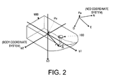
- Fig. 2 is a view for describing a principle for calculating the traveling status of the movable body of the first embodiment.
- a relationship of how an antenna set 100 is installed in a ship 900, with each of a BODY coordinate system (hull coordinate system) and an NED coordinate system (terrestrial coordinate system) is illustrated.
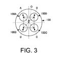
- Fig. 3 is a view illustrating relationships of an arrangement of respective antennas of the antenna set with baseline vectors.
- a status calculating apparatus 10 includes the antenna set 100, correlators 111A, 111B, 111C and 111D, ADR calculating modules 112A, 112B, 112C and 112D, and an operator 12.
- the antenna set 100 is installed at a position with good visibility on the ship 900, in other words, where a reception environment for positioning signals from a plurality of positioning satellites is good.
- the antenna set 100 is installed at a tip end part of a pole installed in a deck of the ship 900.
- the correlator 111B outputs a carrier wave phase difference for every positioning signal from the antenna 100B based on a carrier correlation result between the positioning signal and a replica signal.
- the ADR calculating module 112B integrates the carrier wave phase differences, calculates a carrier wave phase measurement value ADR B , and outputs it to the operator 12. Note that, the correlator 111B calculates a pseudorange PR B based on a code correlation result between each positioning signal from the antenna 100B and the replica signal, and outputs it to the operator 12.
- the correlator 111C outputs a carrier wave phase difference for every positioning signal from the antenna 100C based on a carrier correlation result between the positioning signal and a replica signal.
- the ADR calculating module 112C integrates the carrier wave phase differences, calculates a carrier wave phase measurement value ADR C , and outputs it to the operator 12. Note that, the correlator 111C calculates a pseudorange PR C based on a code correlation result between each positioning signal from the antenna 100C and the replica signal, and outputs it to the operator 12.
- the correlator 111D outputs a carrier wave phase difference for every positioning signal from the antenna 100D based on a carrier correlation result between the positioning signal and a replica signal.
- the ADR calculating module 112D integrates the carrier wave phase differences, calculates a carrier wave phase measurement value ADR D , and outputs it to the operator 12. Note that, the correlator 111D calculates a pseudorange PR D based on a code correlation result between each positioning signal from the antenna 100D and the replica signal, and outputs it to the operator 12.
- the operator 12 of this embodiment calculates an attitude angle but not positional coordinates and a speed as described below, and therefore, the correlators 111A, 111B, 111C and 111D and the ADR calculating modules 112A, 112B, 112C and 112D only need to calculate at least the carrier wave phase measurement values ADR A , ADR B , ADR C and ADR D .
- the operator 12 includes a baseline vector calculating module 120 and an attitude angle calculating module 121.
- the baseline vector calculating module 120 calculates a plurality of baseline vectors by using the carrier wave phase measurement values ADR A , ADR B , ADR C and ADR D .
- Each baseline vector is determined by combining two of the plurality of installed antennas. Specifically, in this embodiment, six baseline vectors including baseline vectors AB, BC, CD, DA, BD and CA are calculated.
- One representative calculating method includes calculating a double phase difference for two antennas and two positioning satellites, determining an integer value ambiguity, and determining the baseline vector by using the integer value ambiguity.
- the baseline vector AB starts from the central position A of the antenna 100A and ends at the central position B of the antenna 100B.
- the baseline vector BC starts from the central position B of the antenna 100B and ends at the central position C of the antenna 100C.
- the baseline vector CD starts from the central position C of the antenna 100C and ends at the central position D of the antenna 100D.
- the baseline vector DA starts from the central position D of the antenna 100D and ends at the central position A of the antenna 100A.
- the baseline vector BD starts from the central position B of the antenna 100B and ends at the central position D of the antenna 100D.
- the baseline vector CA starts from the central position C of the antenna 100C and ends at the central position A of the antenna 100A.
- the attitude angle calculating module 121 selects a plurality of baseline vectors from the above baseline vectors and calculates the attitude angle based on the plurality of selected baseline vectors.
- the calculation method of the attitude angle performed by the operator 12 is described later in detail.
- the attitude angle is composed of the pitch angle ⁇ ( ⁇ h ), the roll angle ⁇ ( ⁇ h ), and the yaw angle ⁇ ( ⁇ h ).
- the pitch angle ⁇ ( ⁇ h ), the roll angle ⁇ ( ⁇ h ), and the yaw angle ⁇ ( ⁇ h ) are indicated in the BODY coordinate system. As illustrated in Fig.
- the BODY coordinate system is formed by a b1 axis that is parallel to a heading of the ship 900, a b2 axis that is parallel to a steering direction of the ship 900, and a b3 axis that is perpendicular to the b1 and b2 axes.
- the b3 axis is parallel to the vertical direction in the state where the ship 900 is not rocking.
- the center Pa of the BODY coordinate system is set to the center of gravity position of the ship 900.
- the pitch angle ⁇ ( ⁇ h ) is an angle in a plane defined by the b1 and b3 axes and indicates an amount of movement of bow and stern of the ship in the vertical direction.
- the roll angle ⁇ ( ⁇ h ) is an angle in a plane defined by the b2 and b3 axes and indicates an amount of movement of port and starboard sides of the ship in the vertical direction.
- the yaw angle ⁇ ( ⁇ h ) is an angle in a plane defined by the b1 and b2 axes and indicates an amount of movement of the heading of the ship in a horizontal plane.
- the attitude angle calculating module 121 calculates a plurality of pitch angles ⁇ , a plurality of roll angles ⁇ , and a plurality of yaw angles ⁇ , and outputs a representative pitch angle ⁇ h , a representative roll angle ⁇ h , and a representative yaw angle ⁇ h , as the attitude angle [ ⁇ h , ⁇ h , ⁇ h ].
- Fig. 4 is a schematic flowchart of the attitude angle calculation performed by the status calculating apparatus of this embodiment.
- the positioning signals are received by each of the antennas 100A, 100B, 100C and 100D, and the carrier wave phase measurement values ADR A , ADR B , ADR C and ADR D are calculated for the antennas 100A, 100B, 100C and 100D, respectively (S101).
- the operator 12 calculates the plurality of baseline vectors AB, BC, CD, DA, BD and CA by using the carrier wave phase measurement values ADR A , ADR B , ADR C and ADR D (S102).
- the operator 12 calculates the plurality of pitch angles ⁇ , the plurality of roll angles ⁇ , and the plurality of yaw angles ⁇ by using the plurality of baseline vectors.
- the operator 12 determines the representative values of the plurality of pitch angles ⁇ , the plurality of roll angles ⁇ , and the plurality of yaw angles ⁇ , respectively, and outputs them as the attitude angle [ ⁇ h , ⁇ h , ⁇ h ] (S103).
- the rotations from the BODY coordinate system to the NED coordinate system are set as roll, pitch and yaw in the order of the rotation, and the respective angles are set as [ ⁇ , ⁇ , ⁇ ], i.e., the roll angle ⁇ , the pitch angle ⁇ , and the yaw angle ⁇ .
- the antenna arrangement is parallel to the ship 900 as described above, in other words, on a plane orthogonal to the b3 axis in Fig. 2 .
- the conversion equation from the BODY coordinate system into the NED coordinate system can be indicated by the following equation by having a rotation matrix as C b n .
- x n C b n ⁇ x b
- Equation 3 When Equation 3 is indicated by respective components and the right side is calculated, it becomes the following equation.
- x N x E x D rcos ⁇ cos ⁇ cos ⁇ + rsin ⁇ ⁇ cos ⁇ sin ⁇ sin ⁇ - sin ⁇ cos ⁇ rcos ⁇ sin ⁇ cos ⁇ + rsin ⁇ ⁇ sin ⁇ sin ⁇ sin ⁇ - cos ⁇ cos ⁇ - rcos ⁇ sin ⁇ + rsin ⁇ cos ⁇ sin ⁇
- Equation 7 sin - 1 ⁇ x D ⁇ 2 r 2 ⁇ sin ⁇ 1 - x D ⁇ 1 r 1 ⁇ sin ⁇ 2 sin ⁇ 2 - ⁇ 1
- the pitch angle ⁇ can be calculated.
- Equation 4 tan - 1 ⁇ - sin ⁇ cos ⁇ ⁇ x N + cos ⁇ cos ⁇ + sin ⁇ sin ⁇ sin ⁇ ⁇ x E cos ⁇ cos ⁇ + sin ⁇ sin ⁇ sin ⁇ ⁇ x N + sin ⁇ cos ⁇ ⁇ x E
- the yaw angle ⁇ can be calculated.
- the operator 12 of this embodiment calculates the attitude angle [ ⁇ h , ⁇ h , ⁇ h ] specifically along the following flow.
- Fig. 5 is a specific flowchart of the attitude angle calculation performed by the operator.
- the operator 12 determines whether the antennas are arranged having a baseline vector in parallel to the heading (S130). If the result is positive, the flow proceeds to S131, but if it is negative, the flow proceeds to S 138, where the pitch angle ⁇ , the representative roll angle ⁇ h , and the representative yaw angle ⁇ h are calculated in a different flow. In this embodiment, the result of S130 is positive. Then, the operator 12 calculates the pitch angle ⁇ by using the two baseline vectors, with the operation method indicated by Equation 8 described above. More specifically, by substituting, into Equation 8, the calculated two baseline vectors and the angles of the two baseline vectors with respect to the heading, the pitch angle ⁇ is calculated. Here, the operator 12 changes the combination of the two baseline vectors to be selected, and calculates the pitch angle ⁇ for every pair of the baseline vectors (S131).
- the operator 12 calculates the representative pitch angle ⁇ h of the plurality of pitch angles ⁇ (S132). Specifically, for example, the operator 12 calculates an average value of the plurality of pitch angles ⁇ and sets it as the representative pitch angle ⁇ h .
- the operator 12 calculates the roll angle ⁇ by using the representative pitch angle ⁇ h and the single baseline vector, with the operation method indicated by Equation 7 described above. More specifically, by substituting, into Equation 7, the representative pitch angle ⁇ h calculated in the above processing, the calculated single baseline vector, and the angle of the single baseline vector, the roll angle ⁇ is calculated.
- the operator 12 changes the baseline vector to be combined with the representative pitch angle ⁇ h , and calculates the roll angle ⁇ for every combination (S133).
- the operator 12 calculates the representative roll angle ⁇ h of the plurality of roll angle ⁇ (S134). Specifically, for example, the operator 12 calculates an average value of the plurality of roll angles ⁇ and sets it as the representative roll angle ⁇ h .
- the operator 12 calculates the yaw angle ⁇ by using the representative pitch angle ⁇ h , the representative roll angle ⁇ h , and the single baseline vector, with the operation method indicated by Equation 9 described above. More specifically, by substituting, into Equation 9, the representative pitch angle ⁇ h and the representative roll angle ⁇ h calculated in the above processing, the calculated single baseline vector, and the angle of the single baseline vector, the yaw angle ⁇ is calculated.
- the operator 12 changes the baseline vector to be combined with the representative pitch angle ⁇ h and the representative roll angle ⁇ h , and calculates the yaw angle ⁇ for every combination (S 135).
- the operator 12 calculates the representative yaw angle ⁇ h of the plurality of yaw angles ⁇ (S136). Specifically, for example, the operator 12 calculates an average value of the plurality of yaw angles ⁇ and sets it as the representative yaw angle ⁇ h .
- the operator 12 determines the representative pitch angle ⁇ h , the representative roll angle ⁇ h , and the representative yaw angle ⁇ h to be the attitude angle [ ⁇ h , ⁇ h , ⁇ h ] (S137).
- a plurality of components can be calculated, and the number of the plurality of components corresponds to the number of the calculated baseline vectors. Then, by using the representative value (e.g., the average value) of the plurality of attitude angle components of each kind, an observation error in each kind of attitude angle components is reduced. Therefore, the attitude angle can be calculated highly accurately.
- the representative value e.g., the average value
- an antenna interval can be narrowed compared to the conventional configuration.
- the antenna arrangement area can be smaller, and moreover, the antenna set can be downsized.
- the average value described above as the representative value may be a weighted average value or a non-weighted average value.
- the weight amount can be determined based on the relationship between the direction of each baseline vector used for calculating the attitude angle and the direction of each attitude angle component, for example.
- the weighting may be performed based on the positioning accuracy at each antenna position. For example, the weight amount may be set to be larger for the baseline vector using the antenna with higher positioning accuracy.
- the average value is calculated as the representative value is described; however, other kinds of statistic values, for example, a medium value, may be used.
- the attitude angle can be calculated highly accurately as a whole.
- the plurality of antennas 100A, 100B, 100C and 100D are arranged in a plane orthogonal to the b3 axis of the BODY coordinate system such that they are at the same distance from the arrangement central position O as each other.
- the antennas 100A, 100B, 100C and 100D are at rotational symmetric positions, forming 90° therebetween centering on the arrangement central position O.
- the antennas 100A, 100B, 100C and 100D are arranged in a pattern in which they are samely arranged in both of the b1 and b2 axes. In other words, the antennas 100A, 100B, 100C and 100D are arranged isotropically.
- the pitch and roll angles ⁇ and ⁇ can be calculated at substantially the same accuracy.
- the pitch and roll angles ⁇ and ⁇ can be calculated while maintaining the isotropy, and the yaw angle which is calculated using the pitch and roll angles can be calculated at similar accuracy regardless of the direction to which the ship rocks.
- the attitude angle can be calculated highly accurately as a whole without any deviation in the directions.
- the pitch and roll angles ⁇ and ⁇ can be calculated while maintaining the isotropy.
- the installation of the antenna set in the ship becomes easy since the installation direction of the antenna set in the ship does not have much influence.
- the antennas are arranged isotropically; however, they may be arranged substantially isotropically. In other words, the plurality of antennas may be slightly offset. Also in this case, the attitude angle can be calculated at substantially similar accuracy to the case with the isotropy.
- the antenna set 100 may be arranged in the ship 900 so that the baseline vector coupling the central position A of the antenna 100A to the central position B of the antenna 100B and the baseline vector coupling the central position C of the antenna 100C to the central position D of the antenna 100D become parallel to the heading of the ship 900 (the b1 axial direction of the BODY coordinate system).
- the attitude angle calculation becomes easy as described later.
- the baseline vector parallel to the heading becomes short. Therefore, the baseline vector parallel to the heading can be calculated swiftly and highly accurately. Thus, the attitude angle can be calculated more swiftly depending on the situation.
- Fig. 6 is a flowchart of the calculation of the pitch angle ⁇ .
- the pitch angle ⁇ is calculated using the baseline vector (S314). In this case, the pitch angle ⁇ can be calculated based on Equation 8 described above, by having ⁇ 1 as 0° or ⁇ 2 as 180°.
- the pitch angle ⁇ is calculated based on Equation 8 described above, by selecting two of the plurality of determined baseline vectors and using the two baseline vectors (S316).
- Fig. 7 is a flowchart of the calculation of the roll angle ⁇ .
- the roll angle ⁇ is calculated based on Equation 7 described above, by selecting one of the plurality of determined baseline vectors and using the selected baseline vector and the representative pitch angle ⁇ h as a pair (S327).
- Fig. 8 is a flowchart of the calculation of the yaw angle ⁇ .
- the representative pitch angle ⁇ h is usable (S321: YES)
- whether the representative roll angle ⁇ h is usable is determined. If the representative roll angle ⁇ h is not usable (S332: NO), whether the baseline vector parallel to the heading exists is detected. If the baseline vector parallel to the heading does not exist (S334: NO), the calculation of the yaw angle ⁇ is determined as not available (S336). If the baseline vector parallel to the heading exists (S334: YES), the yaw angle ⁇ is calculated by using the baseline vector and the representative pitch angle ⁇ h (S335). Note that, with the calculation method of the yaw angle ⁇ in this case, since the movement of the baseline vector in the b2 axis corresponds to the yaw angle ⁇ , the yaw angle ⁇ can be calculated by using this.
- the yaw angle ⁇ is calculated based on Equation 9 described above, by using the representative pitch and roll angles ⁇ h and ⁇ h and the baseline vector as a set (S333).
- the attitude angle can be calculated with less number of baseline vectors depending on the antenna arrangement.
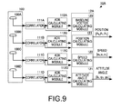
- FIG. 9 is a block diagram illustrating a configuration of the status calculating apparatus of the second embodiment of the present invention.
- a status calculating apparatus 10A of this embodiment is different from the status calculating apparatus 10 of the first embodiment in that position (positional coordinates) and speed of the ship are also calculated in addition to the attitude angle.
- An operator 12A includes a baseline vector calculating module 120, an attitude angle calculating module 121, a speed calculating module 122, and a position calculating module 123.
- the baseline vector calculating module 120 has the same configuration as that in the operator 12 of the first embodiment, and performs the same processing.
- the attitude angle calculating module 121 has the same configuration as that in the operator 12 of the first embodiment, and performs the same processing.
- the speed calculating module 122 calculates a speed component at the position of the antenna 100A based on the carrier wave phase measurement value ADR A .
- the speed calculating module 122 calculates a speed component at the position of the antenna 100B based on the carrier wave phase measurement value ADR B .
- the speed calculating module 122 calculates a speed component at the position of the antenna 100C based on the carrier wave phase measurement value ADR C .
- the speed calculating module 122 calculates a speed component at the position of the antenna 100D based on the carrier wave phase measurement value ADR D .
- the speed calculating module 122 calculates the speed of the ship 900 based on the speed components at the antennas 100A, 100B, 100C and 100D.
- the speed calculating module 122 can calculate the speed of the ship at a specific position thereof (e.g., a bow position of the ship 900) without limiting to the positions of the antennas 100A, 100B, 100C and 100D.
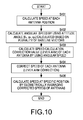
- Fig. 10 is a flowchart of the speed calculation of the second embodiment of the present invention.
- the speed calculating module 122 calculates the speed component at each antenna position where the carrier wave phase measurement value is calculated (S401). Here, the speed calculating module 122 calculates the speed component based on respective time change amount of the carrier wave phase measurement value.
- the speed calculating module 122 calculates an angular speed at each antenna position based on the time change amount of the attitude angle [ ⁇ h , ⁇ h , ⁇ h ] (S402).
- the speed calculating module 122 calculates a speed calculation correction value at each antenna position (lever arm correction value) by using the calculated angular speed (S403).
- the speed calculation correction value (lever arm correction value) is a correction value for suppressing influence of an angular speed on a speed caused by a lever arm effect.
- the lever arm effect indicates a case where, when the angular speed is added to the ship 900, the angular speed influences the speed to be observed at a position other than a center of gravity Pa of the ship.
- the speed calculating module 122 corrects the speed at each antenna position by using the speed calculation correction value (S404).
- the speed calculating module 122 calculates the speed at the specific position by using the corrected speeds at the respective antenna positions.
- the speed calculating module 122 calculates a geometric average value based on distances of the respective antenna positions from the specific position and calculates the speed at the specific position (e.g., the position where the center of gravity Pa is, the bow position of the ship 900) using the geometric average value (S405).
- the speed calculating module 122 may calculate the speed by the following method.
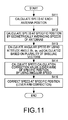
- Fig. 11 is another flowchart of the speed calculation of the second embodiment of the present invention.
- the speed calculating module 122 calculates the speed component at each antenna position where the carrier wave phase measurement value is calculated (S411). Here, the speed calculating module 122 calculates the speed component based on respective time change amount of the carrier wave phase measurement value.
- the speed calculating module 122 calculates the speed at the specific position by using the speed components at the respective antenna positions.
- the speed calculating module 122 calculates a geometric average value based on distances of the respective antenna positions from the specific position and calculates the speed at the specific position by using the geometric average value (S412).
- the speed calculating module 122 calculates an angular speed at each antenna position based on the time change amounts of the attitude angle [ ⁇ h , ⁇ h , ⁇ h ] (S413).
- the speed calculating module 122 calculates a speed calculation correction value (lever arm correction value) for the specific position by using the calculated angular speed (S414). Note that, the processing at S413 and S414 may be performed in parallel with or previous to the speed calculation at S411 and S412 described above.
- the speed calculating module 122 corrects the speed at the specific position by using the speed calculation correction value for the specific position (S415).
- Fig. 12A is a view illustrating the position for which the geometric average value is calculated
- Fig. 12B is a view illustrating a situation where the position for which the geometric average value is calculated deviates from the specific position, and a concept of correcting the deviation.
- Fig. 12 illustrates a case where the specific position is the arrangement central position O of the plurality of antennas 100A, 100B, 100C and 100D.
- the geometric average value of the speeds at all the positions of the antennas 100A, 100B, 100C and 100D is the speed at the arrangement central position O (specific position).
- the geometric average value becomes a value at a geometric average position O' of the antennas 100A, 100B and 100C, which is different from that at the arrangement central position O.
- position errors of geometric average positions of combinations of at least two antennas with respect to the geometric average position (arrangement central position O) of all the antennas 100A, 100B, 100C and 100D are stored in advance.
- correction values for correcting the position errors are set in advance.
- the correction values are set by taking the change amount of the speed calculation correction value (lever arm correction value) into consideration.
- the geometric average value of the speeds may be corrected according to the combination of the antennas.
- the example in which the arrangement central position O of the all the antennas 100A, 100B, 100C and 100D is set to be the specific position as a reference position; however, even if it was a different position, by performing the correction with a similar concept to the above concept, the speed of the specific position can be corrected accurately.
- the position calculating module 123 calculates positional coordinates of the antenna 100A based on either one of the pseudorange PR A and the carrier wave phase measurement value ADR A .
- the position calculating module 123 calculates positional coordinates of the antenna 100B based on either one of the pseudorange PR B and the carrier wave phase measurement value ADR B .
- the position calculating module 123 calculates positional coordinates of the antenna 100C based on either one of the pseudorange PR C and the carrier wave phase measurement value ADR C .
- the position calculating module 123 calculates positional coordinates of the antenna 100D based on either one of the pseudorange PR D and the carrier wave phase measurement value ADR D .
- the position calculating module 123 calculates the positional coordinates of the specific position based on the positional coordinates of the antennas 100A, 100B, 100C and 100D.
- the specific position is the arrangement central position O or the bow position of the ship 900, for example.
- Fig. 13 is a flowchart of the position calculation of the second embodiment of the present invention.
- the position calculating module 123 calculates the positional coordinates of each antenna position where either one of the pseudorange and the carrier wave phase measurement value is calculated (S501).
- the positional coordinates can be calculated in the earlier stage of calculating the positional coordinates compared to using the carrier wave phase measurement value, and by using the carrier wave phase measurement value, the positional coordinates can be calculated more highly accurately compared to using the pseudorange.
- the position calculating module 123 calculates a position calculation correction value for each antenna position by using the attitude angle [ ⁇ h , ⁇ h , ⁇ h ] calculated based on the plurality of baseline vectors as described above (S502).
- the position calculating module 123 corrects the positional coordinates of each antenna position by using the position calculation correction value (S503).
- the position calculating module 123 calculates the positional coordinates of the specific position by using the corrected positional coordinates at the respective antenna positions.
- the position calculating module 123 calculates a geometric average value based on distances of the respective antenna positions from the specific position and calculates the positional coordinates of the specific position by using the geometric average value (S504).
- the position calculation correction value can be calculated highly accurately.
- a position calculation error due to the rocking of the ship can be suppressed highly accurately and the positional coordinates of the specific position can be calculated highly accurately.
- the position calculating module 123 may calculate the speed by the following method.
- Fig. 14 is another flowchart of the position calculation of the second embodiment of the present invention.
- the position calculating module 123 calculates the positional coordinates of each antenna position where either one of the pseudorange and the carrier wave phase measurement value is calculated (S511).
- the position calculating module 123 calculates the positional coordinates of the specific position by using a geometric average value which is based on distances of the respective antenna positions from the specific position (S512).
- the position calculating module 123 calculates a position calculation correction value for the specific position by using the attitude angle [ ⁇ h , ⁇ h , ⁇ h ] calculated based on the plurality of baseline vectors as described above (S513).
- the position calculating module 123 corrects the positional coordinates of the specific position by using the position calculation correction value for the specific position (S514).
- the position calculation correction value can be calculated highly accurately.
- a position calculation error due to the rocking of the ship can be suppressed highly accurately and the positional coordinates of the specific position can be calculated highly accurately.
- the correction illustrated in Fig. 12B in other words, the correction according to the combination of the antennas where the carrier wave phase measurement value is successfully calculated, can be applied.
- Fig. 15 is a block diagram illustrating a schematic configuration of the ship installed with the status calculating apparatus of the second embodiment. Note that, here, the ship 900 is described as an example of the movable body; however, the configuration of this embodiment can also be applied to other movable bodies on/in a water, movable bodies on land (e.g., an automobile), and movable bodies in the air (e.g., aircrafts).
- the ship 900 includes a status calculating apparatus 10A, a controller 901, an engine 902, and a helm 903.
- the status calculating apparatus 10A calculates and outputs the position [P N , P E , P D ], the speed [V N , V E , V D ], and the attitude angle [ ⁇ h , ⁇ h , ⁇ h ] by using the above methods.
- the controller 901 performs traveling control processing by using the position [P N , P E , P D ], the speed [V N , V E , V D ], and the attitude angle [ ⁇ h , ⁇ h , ⁇ h ]. For example, the controller 901 performs an automatic traveling control for estimating the most efficient traveling course based on a current position of the ship and a destination, and a dynamic positioning control for stopping at a fixed position when the ship position is changing.
- the controller 901 generates a control signal for the engine 902 and the helm 903 based on the set control contents.
- the engine 902 and the helm 903 operate based on the control signal.
- the automatic traveling control can cause the ship 900 to automatically travel along the optimal traveling course.
- the dynamic positioning control can be performed highly accurately.
- Figs. 16 , 17 and 18 are views illustrating patterns of derivative arrangements of the plurality of antennas.
- An antenna set 101 in Fig. 16 includes the three antennas 100A, 100B and 100C.
- the antenna 100A is arranged separated from the antennas 100B and 100C to the heading.
- the antennas 100B and 100C are arranged in the direction orthogonal to the heading.
- the antenna 100A is arranged on a perpendicular bisector of the position of the antenna 100B and the position of the antenna 100C. A distance between the position of the antenna 100B and the position of the antenna 100C is shorter than that between the position of the antenna 100A and the midpoint of the position of the antenna 100B and the position of the antenna 100C.
- the baseline vector formed by the antennas 100A and 100B and the baseline vector formed by the antennas 100C and 100A become a long baseline vector in the heading. Therefore, since a plurality of baseline vectors that are long in the heading can be secured, the pitch and yaw angles ⁇ and ⁇ can be calculated highly accurately.
- An antenna set 102 in Fig. 17 includes the four antennas 100A, 100B, 100C and 100D.
- the antennas 100A and 100C are arranged in the heading.
- the antennas 100B and 100D are arranged in the direction orthogonal to the heading.
- a distance between the position of the antenna 100A and the position of the antenna 100C is significantly longer than that between the position of the antenna 100B and the position of the antenna 100D.
- the midpoint of the position of the antenna 100A and the position of the antenna 100C coincides with the midpoint of the position of the antenna 100B and the position of the antenna 100D.
- the antenna set 102 includes the antennas 100A, 100B, 100C and 100D arranged in a rhombic shape of which a diagonal line parallel to the heading is longer than a diagonal line orthogonal to the heading.
- the number of baseline vectors that are long in the heading can be increased.
- the pitch and yaw angles ⁇ and ⁇ can be calculated more highly accurately.
- An antenna set 103 in Fig. 18 is the same as the antenna set 101 in Fig. 16 with additional antennas 100D and 100E.
- the antennas 100D and 100E are arranged on a perpendicular bisector of the position of the antenna 100B and the position of the antenna 100C.
- the antennas 100D and 100E are arranged between the position of the antenna 100A and the midpoint of the position of the antenna 100B and the position of the antenna 100C. In other words, the antennas 100A, 100D and 100E are arranged separated from each other in the heading.
- the number of baseline vectors that are long in the heading can be increased.
- the pitch and yaw angles ⁇ and ⁇ can be calculated more highly accurately.
- the antenna arrangements in Figs. 16 and 18 may be a plane symmetric arrangement where a plane orthogonal to the heading is taken as a reference plane.
- the arrangement pattern of the antennas is not limited to the above examples.
- the plurality of antennas may be arranged to form a baseline vector having a long vector component in an axial direction included in two planes containing the specific attitude angle component.
- the pitch, roll, and yaw angles ⁇ , ⁇ and ⁇ which are the respective components of the attitude angle, are calculated based on the baseline vectors is described.
- the yaw angle may be calculated by the following method.
- the pitch and roll angles ⁇ and ⁇ are measured by an inertia sensor.
- the operator calculates the yaw angle by using the pitch and roll angles ⁇ and ⁇ measured by the inertia sensor and the baseline vectors based on the positioning signals.
- the pitch angle ⁇ is measured by the inertia sensor and the roll and yaw angles ⁇ and ⁇ are sequentially calculated based on the pitch angle ⁇ measured by the inertia sensor, and the baseline vectors.
- the configuration of the present invention works more effectively.
- the baseline length is shorter than half the length of the wavelength, although the determination of the integer value ambiguity becomes easy, since the baseline length is short, the calculation accuracy of the baseline vector is low. Thus, the accuracy of the attitude angle to be calculated becomes low, causing degradation of the accuracy in the operation as the attitude angle detecting sensor.
- the attitude angle is calculated by using the plurality of baseline vectors, the accuracy of the attitude angle can be improved regardless of the baseline length. Therefore, even with the antenna arrangement which causes the baseline length to be shorter than half of the wavelength, the attitude angle can be calculated highly accurately. By having the baseline length of shorter than half of the wavelength, the determination of the integer value ambiguity becomes easy and the highly accurate attitude angle can be obtained swiftly. Moreover, the antenna interval can be shortened and the antenna set can be downsized.
Landscapes
- Engineering & Computer Science (AREA)
- Radar, Positioning & Navigation (AREA)
- Remote Sensing (AREA)
- Physics & Mathematics (AREA)
- General Physics & Mathematics (AREA)
- Computer Networks & Wireless Communication (AREA)
- Aviation & Aerospace Engineering (AREA)
- Automation & Control Theory (AREA)
- Position Fixing By Use Of Radio Waves (AREA)
- Traffic Control Systems (AREA)
Applications Claiming Priority (1)
| Application Number | Priority Date | Filing Date | Title |
|---|---|---|---|
| JP2013153402A JP6310202B2 (ja) | 2013-07-24 | 2013-07-24 | 状態算出装置、移動体、状態算出方法、および状態算出プログラム |
Publications (3)
| Publication Number | Publication Date |
|---|---|
| EP2848963A2 true EP2848963A2 (de) | 2015-03-18 |
| EP2848963A3 EP2848963A3 (de) | 2015-06-17 |
| EP2848963B1 EP2848963B1 (de) | 2023-03-22 |
Family
ID=51359254
Family Applications (1)
| Application Number | Title | Priority Date | Filing Date |
|---|---|---|---|
| EP14178125.2A Active EP2848963B1 (de) | 2013-07-24 | 2014-07-23 | Verfahren und Vorrichtung zur Statusberechnung sowie beweglicher Körper |
Country Status (4)
| Country | Link |
|---|---|
| US (1) | US9342075B2 (de) |
| EP (1) | EP2848963B1 (de) |
| JP (1) | JP6310202B2 (de) |
| CN (1) | CN104345326B (de) |
Families Citing this family (47)
| Publication number | Priority date | Publication date | Assignee | Title |
|---|---|---|---|---|
| TWI498581B (zh) * | 2014-01-03 | 2015-09-01 | Ind Tech Res Inst | 衛星定位方法、衛星定位裝置與電腦可讀取媒體 |
| CN105940320B (zh) * | 2014-02-21 | 2020-01-07 | 古野电气株式会社 | 结构物的位移检测装置、结构物的位移的共有系统、结构物的位移检测方法、以及结构物的位移检测系统 |
| WO2017120304A1 (en) * | 2016-01-08 | 2017-07-13 | Commscope Technologies Llc | Improving azimuth determination accuracy using multiple gnss antennas |
| KR101758140B1 (ko) | 2016-02-05 | 2017-07-17 | 주식회사 피피솔 | Dgnss 측위 방법 및 이를 이용하는 gnss 수신기 |
| JPWO2017141614A1 (ja) * | 2016-02-19 | 2018-11-29 | 古野電気株式会社 | 津波観測装置、津波観測システム、津波観測方法 |
| US10640190B1 (en) | 2016-03-01 | 2020-05-05 | Brunswick Corporation | System and method for controlling course of a marine vessel |
| US10322787B2 (en) | 2016-03-01 | 2019-06-18 | Brunswick Corporation | Marine vessel station keeping systems and methods |
| US10671073B2 (en) * | 2017-02-15 | 2020-06-02 | Brunswick Corporation | Station keeping system and method |
| US11449059B2 (en) | 2017-05-01 | 2022-09-20 | Symbol Technologies, Llc | Obstacle detection for a mobile automation apparatus |
| AU2018261257B2 (en) | 2017-05-01 | 2020-10-08 | Symbol Technologies, Llc | Method and apparatus for object status detection |
| WO2018201423A1 (en) | 2017-05-05 | 2018-11-08 | Symbol Technologies, Llc | Method and apparatus for detecting and interpreting price label text |
| CN110832342A (zh) * | 2017-06-30 | 2020-02-21 | 古野电气株式会社 | 航迹预测装置、航迹预测方法及航迹预测程序 |
| CN107704681B (zh) * | 2017-09-30 | 2021-06-04 | 江西洪都航空工业集团有限责任公司 | 一种飞机地面视野范围的计算方法 |
| CN111465874B (zh) * | 2017-12-01 | 2024-06-07 | 古野电气株式会社 | 摆动观测装置、摆动观测方法及存储介质 |
| CN108733057A (zh) * | 2018-05-23 | 2018-11-02 | 江苏大学 | 一种基于自抗扰技术的水产养殖明轮船航向控制方法 |
| US11506483B2 (en) | 2018-10-05 | 2022-11-22 | Zebra Technologies Corporation | Method, system and apparatus for support structure depth determination |
| US11090811B2 (en) | 2018-11-13 | 2021-08-17 | Zebra Technologies Corporation | Method and apparatus for labeling of support structures |
| CN109443349A (zh) * | 2018-11-14 | 2019-03-08 | 广州中海达定位技术有限公司 | 一种姿态航向测量系统及其融合方法、存储介质 |
| JP7201219B2 (ja) | 2018-11-26 | 2023-01-10 | 株式会社豊田中央研究所 | 測位装置、速度測定装置、及びプログラム |
| US11416000B2 (en) | 2018-12-07 | 2022-08-16 | Zebra Technologies Corporation | Method and apparatus for navigational ray tracing |
| US11079240B2 (en) | 2018-12-07 | 2021-08-03 | Zebra Technologies Corporation | Method, system and apparatus for adaptive particle filter localization |
| CN109814547B (zh) * | 2018-12-24 | 2022-08-05 | 上海大学 | 风浪干扰作用下的无人艇航向保持装置和方法 |
| CA3028708C (en) | 2018-12-28 | 2025-12-09 | Zebra Technologies Corporation | Method, system and apparatus for dynamic loop closure in mapping trajectories |
| US11151743B2 (en) | 2019-06-03 | 2021-10-19 | Zebra Technologies Corporation | Method, system and apparatus for end of aisle detection |
| US11662739B2 (en) | 2019-06-03 | 2023-05-30 | Zebra Technologies Corporation | Method, system and apparatus for adaptive ceiling-based localization |
| US11341663B2 (en) | 2019-06-03 | 2022-05-24 | Zebra Technologies Corporation | Method, system and apparatus for detecting support structure obstructions |
| US11080566B2 (en) | 2019-06-03 | 2021-08-03 | Zebra Technologies Corporation | Method, system and apparatus for gap detection in support structures with peg regions |
| US11402846B2 (en) | 2019-06-03 | 2022-08-02 | Zebra Technologies Corporation | Method, system and apparatus for mitigating data capture light leakage |
| US11960286B2 (en) | 2019-06-03 | 2024-04-16 | Zebra Technologies Corporation | Method, system and apparatus for dynamic task sequencing |
| US11200677B2 (en) * | 2019-06-03 | 2021-12-14 | Zebra Technologies Corporation | Method, system and apparatus for shelf edge detection |
| WO2021020048A1 (ja) * | 2019-08-01 | 2021-02-04 | 古野電気株式会社 | 姿勢計測装置、姿勢計測方法、および、姿勢計測プログラム |
| US11507103B2 (en) | 2019-12-04 | 2022-11-22 | Zebra Technologies Corporation | Method, system and apparatus for localization-based historical obstacle handling |
| US11107238B2 (en) | 2019-12-13 | 2021-08-31 | Zebra Technologies Corporation | Method, system and apparatus for detecting item facings |
| CN111538057A (zh) * | 2019-12-27 | 2020-08-14 | 广东电网有限责任公司电力科学研究院 | 一种北斗定位装置及其定位方法 |
| US11822333B2 (en) | 2020-03-30 | 2023-11-21 | Zebra Technologies Corporation | Method, system and apparatus for data capture illumination control |
| WO2021217457A1 (zh) * | 2020-04-28 | 2021-11-04 | 华为技术有限公司 | 一种定位信息的确定方法及通信装置 |
| CN111504256A (zh) * | 2020-04-29 | 2020-08-07 | 中国北方工业有限公司 | 一种基于最小二乘法的滚转角实时估计方法 |
| US11450024B2 (en) | 2020-07-17 | 2022-09-20 | Zebra Technologies Corporation | Mixed depth object detection |
| CN112099070B (zh) * | 2020-08-24 | 2024-08-27 | 泰斗微电子科技有限公司 | 测向方法、测向装置、测向系统及基准站 |
| US11593915B2 (en) | 2020-10-21 | 2023-02-28 | Zebra Technologies Corporation | Parallax-tolerant panoramic image generation |
| CN112325842B (zh) * | 2020-10-30 | 2022-07-01 | 中国电子科技集团公司第五十四研究所 | 一种多天线平面投影加权测姿方法 |
| CN112800349B (zh) * | 2021-02-02 | 2022-02-18 | 中华人民共和国广东海事局 | 水上移动目标的运动状态获取方法、装置、设备和介质 |
| CN113156369B (zh) * | 2021-04-26 | 2021-10-29 | 哈尔滨工程大学 | 一种海上声学相位中心校准方法 |
| US11954882B2 (en) | 2021-06-17 | 2024-04-09 | Zebra Technologies Corporation | Feature-based georegistration for mobile computing devices |
| CN116736867B (zh) * | 2023-08-10 | 2023-11-10 | 湖南湘船重工有限公司 | 一种无人船避障控制系统 |
| CN118915116A (zh) * | 2024-07-18 | 2024-11-08 | 合肥星北智控科技有限公司 | 基于北斗ⅲ姿态测量的风电塔基形变监测系统和监测方法 |
| CN118897253B (zh) * | 2024-09-18 | 2025-06-10 | 成都诺思特安科技有限公司 | 一种基于非均匀线阵复杂环境下的信号测向方法 |
Citations (1)
| Publication number | Priority date | Publication date | Assignee | Title |
|---|---|---|---|---|
| JP2008014721A (ja) | 2006-07-04 | 2008-01-24 | Hitachi Industrial Equipment Systems Co Ltd | 姿勢算出装置、および、姿勢算出方法 |
Family Cites Families (19)
| Publication number | Priority date | Publication date | Assignee | Title |
|---|---|---|---|---|
| US6052647A (en) * | 1997-06-20 | 2000-04-18 | Stanford University | Method and system for automatic control of vehicles based on carrier phase differential GPS |
| US6005514A (en) * | 1997-09-15 | 1999-12-21 | United States Of America As Represented By The Administrator Of The National Aeronautics And Space Administration | Method for attitude determination using GPS carrier phase measurements from nonaligned antennas |
| JPH11254993A (ja) * | 1998-03-10 | 1999-09-21 | Honda Motor Co Ltd | 車両用姿勢検出装置 |
| JP2001281317A (ja) * | 2000-03-30 | 2001-10-10 | Japan Radio Co Ltd | 移動体姿勢計測システムおよび複数アンテナ配置構造 |
| US6421003B1 (en) * | 2000-05-19 | 2002-07-16 | Sri International | Attitude determination using multiple baselines in a navigational positioning system |
| JP4446569B2 (ja) * | 2000-07-24 | 2010-04-07 | 古野電気株式会社 | キャリア位相相対測位装置 |
| US6754584B2 (en) * | 2001-02-28 | 2004-06-22 | Enpoint, Llc | Attitude measurement using a single GPS receiver with two closely-spaced antennas |
| JP2006126181A (ja) * | 2004-10-01 | 2006-05-18 | Mitsubishi Electric Corp | 移動体姿勢検出装置 |
| JP4563157B2 (ja) * | 2004-12-01 | 2010-10-13 | 古野電気株式会社 | 物体の方位および姿勢検出装置 |
| US8311730B2 (en) * | 2006-11-29 | 2012-11-13 | Neff Ryan A | Vehicle position determination system |
| JP5340543B2 (ja) * | 2007-01-18 | 2013-11-13 | 前田建設工業株式会社 | 仮設構造体の健全性判定システム |
| US8120527B2 (en) * | 2008-01-30 | 2012-02-21 | Javad Gnss, Inc. | Satellite differential positioning receiver using multiple base-rover antennas |
| JP4655139B2 (ja) * | 2008-11-19 | 2011-03-23 | トヨタ自動車株式会社 | 移動体位置測位装置 |
| JP2010216822A (ja) * | 2009-03-13 | 2010-09-30 | Japan Radio Co Ltd | 姿勢計測装置 |
| WO2010140528A1 (ja) * | 2009-06-02 | 2010-12-09 | 古野電気株式会社 | Gnss受信装置 |
| US8633854B2 (en) * | 2009-10-15 | 2014-01-21 | Novatel Inc. | Short and ultra-short baseline phase maps |
| JP5566168B2 (ja) * | 2010-04-02 | 2014-08-06 | 古野電気株式会社 | Gnss受信機、航法装置、信号処理装置、gnss速度補正プログラム及びgnss速度補正方法 |
| EP2405281A1 (de) * | 2010-07-09 | 2012-01-11 | Fraunhofer-Gesellschaft zur Förderung der angewandten Forschung | Verfahren und Vorrichtung zur Bestimmung der Position und Orientierung eines mobilen Senders |
| JP5762131B2 (ja) * | 2011-05-23 | 2015-08-12 | 三菱電機株式会社 | キャリブレーション装置、キャリブレーション装置のキャリブレーション方法およびキャリブレーションプログラム |
-
2013
- 2013-07-24 JP JP2013153402A patent/JP6310202B2/ja active Active
-
2014
- 2014-07-23 CN CN201410353974.8A patent/CN104345326B/zh active Active
- 2014-07-23 EP EP14178125.2A patent/EP2848963B1/de active Active
- 2014-07-23 US US14/339,248 patent/US9342075B2/en active Active
Patent Citations (1)
| Publication number | Priority date | Publication date | Assignee | Title |
|---|---|---|---|---|
| JP2008014721A (ja) | 2006-07-04 | 2008-01-24 | Hitachi Industrial Equipment Systems Co Ltd | 姿勢算出装置、および、姿勢算出方法 |
Also Published As
| Publication number | Publication date |
|---|---|
| JP6310202B2 (ja) | 2018-04-11 |
| US20150032304A1 (en) | 2015-01-29 |
| EP2848963A3 (de) | 2015-06-17 |
| US9342075B2 (en) | 2016-05-17 |
| JP2015025671A (ja) | 2015-02-05 |
| CN104345326B (zh) | 2019-11-01 |
| EP2848963B1 (de) | 2023-03-22 |
| CN104345326A (zh) | 2015-02-11 |
Similar Documents
| Publication | Publication Date | Title |
|---|---|---|
| EP2848963B1 (de) | Verfahren und Vorrichtung zur Statusberechnung sowie beweglicher Körper | |
| US10514469B2 (en) | Attitude angle calculating device, method of calculating attitude angle, and attitude angle calculating program | |
| JP6360199B2 (ja) | 状態算出装置、状態算出方法、および状態算出プログラム | |
| EP2244099B1 (de) | Integrierte satellitennavigation und koppelnavigation positionierungsvorrichtung | |
| CA2777803C (en) | Ultra-short baseline gnss receiver | |
| CA2806124C (en) | A system and method of determining an unambiguous heading direction of a vehicle | |
| US20210165111A1 (en) | Method for determining the position of a vehicle | |
| EP2706379A1 (de) | Verfahren und System zur Bereitstellung der Integrität für die hybride Stellung und wahre Richtungsgabe | |
| US20120242540A1 (en) | Heading determination system using rotation with gnss antennas | |
| WO2014138950A1 (en) | System and method for augmenting a gnss/ins navigation system of a low dynamic vessel using a vision system | |
| WO2018179189A1 (ja) | 車載器、演算装置及びプログラム | |
| US10948292B2 (en) | Sensor error calculating device, attitude angle calculating apparatus, method of calculating sensor error and method of calculating attitude angle | |
| WO2011159185A1 (ru) | Способ и устройство определения направления начала движения | |
| KR101763911B1 (ko) | 자기장 외란이 심한 환경에서 수중체의 선수각 추정 장치 및 그 방법 | |
| JP2012202749A (ja) | 方位測定装置 | |
| US10877163B2 (en) | Method and device for calculating attitude angle | |
| EP3812193B1 (de) | Messvorrichtung | |
| JP6321914B2 (ja) | 移動体情報算出装置、移動体情報取得装置、移動体、移動体情報算出方法、移動体情報取得方法、移動体情報算出プログラム、および移動体情報取得プログラム | |
| KR101707860B1 (ko) | 위성데이터의 위치좌표 오차 보정방법 | |
| Emel'yantsev et al. | Using satellite receivers with a common clock in a small-sized GNSS compass | |
| JP2003279635A (ja) | 移動体位置計測システム | |
| JP5180447B2 (ja) | キャリア位相相対測位装置及び方法 | |
| CN114207476A (zh) | 姿态计测装置、姿态计测方法及姿态计测程序 | |
| JP2002267738A (ja) | 測定装置 | |
| JP2009186355A (ja) | 航行体の姿勢検出方法及び装置 |
Legal Events
| Date | Code | Title | Description |
|---|---|---|---|
| PUAI | Public reference made under article 153(3) epc to a published international application that has entered the european phase |
Free format text: ORIGINAL CODE: 0009012 |
|
| 17P | Request for examination filed |
Effective date: 20140723 |
|
| AK | Designated contracting states |
Kind code of ref document: A2 Designated state(s): AL AT BE BG CH CY CZ DE DK EE ES FI FR GB GR HR HU IE IS IT LI LT LU LV MC MK MT NL NO PL PT RO RS SE SI SK SM TR |
|
| AX | Request for extension of the european patent |
Extension state: BA ME |
|
| PUAL | Search report despatched |
Free format text: ORIGINAL CODE: 0009013 |
|
| AK | Designated contracting states |
Kind code of ref document: A3 Designated state(s): AL AT BE BG CH CY CZ DE DK EE ES FI FR GB GR HR HU IE IS IT LI LT LU LV MC MK MT NL NO PL PT RO RS SE SI SK SM TR |
|
| AX | Request for extension of the european patent |
Extension state: BA ME |
|
| RIC1 | Information provided on ipc code assigned before grant |
Ipc: G01S 19/54 20100101ALI20150511BHEP Ipc: G01S 19/52 20100101AFI20150511BHEP |
|
| R17P | Request for examination filed (corrected) |
Effective date: 20151204 |
|
| RBV | Designated contracting states (corrected) |
Designated state(s): AL AT BE BG CH CY CZ DE DK EE ES FI FR GB GR HR HU IE IS IT LI LT LU LV MC MK MT NL NO PL PT RO RS SE SI SK SM TR |
|
| STAA | Information on the status of an ep patent application or granted ep patent |
Free format text: STATUS: EXAMINATION IS IN PROGRESS |
|
| 17Q | First examination report despatched |
Effective date: 20180903 |
|
| GRAP | Despatch of communication of intention to grant a patent |
Free format text: ORIGINAL CODE: EPIDOSNIGR1 |
|
| STAA | Information on the status of an ep patent application or granted ep patent |
Free format text: STATUS: GRANT OF PATENT IS INTENDED |
|
| INTG | Intention to grant announced |
Effective date: 20221026 |
|
| GRAS | Grant fee paid |
Free format text: ORIGINAL CODE: EPIDOSNIGR3 |
|
| GRAA | (expected) grant |
Free format text: ORIGINAL CODE: 0009210 |
|
| STAA | Information on the status of an ep patent application or granted ep patent |
Free format text: STATUS: THE PATENT HAS BEEN GRANTED |
|
| AK | Designated contracting states |
Kind code of ref document: B1 Designated state(s): AL AT BE BG CH CY CZ DE DK EE ES FI FR GB GR HR HU IE IS IT LI LT LU LV MC MK MT NL NO PL PT RO RS SE SI SK SM TR |
|
| REG | Reference to a national code |
Ref country code: GB Ref legal event code: FG4D |
|
| REG | Reference to a national code |
Ref country code: CH Ref legal event code: EP |
|
| REG | Reference to a national code |
Ref country code: DE Ref legal event code: R096 Ref document number: 602014086494 Country of ref document: DE |
|
| REG | Reference to a national code |
Ref country code: IE Ref legal event code: FG4D |
|
| REG | Reference to a national code |
Ref country code: AT Ref legal event code: REF Ref document number: 1555650 Country of ref document: AT Kind code of ref document: T Effective date: 20230415 |
|
| P01 | Opt-out of the competence of the unified patent court (upc) registered |
Effective date: 20230523 |
|
| REG | Reference to a national code |
Ref country code: LT Ref legal event code: MG9D |
|
| REG | Reference to a national code |
Ref country code: NL Ref legal event code: MP Effective date: 20230322 |
|
| PG25 | Lapsed in a contracting state [announced via postgrant information from national office to epo] |
Ref country code: RS Free format text: LAPSE BECAUSE OF FAILURE TO SUBMIT A TRANSLATION OF THE DESCRIPTION OR TO PAY THE FEE WITHIN THE PRESCRIBED TIME-LIMIT Effective date: 20230322 Ref country code: NO Free format text: LAPSE BECAUSE OF FAILURE TO SUBMIT A TRANSLATION OF THE DESCRIPTION OR TO PAY THE FEE WITHIN THE PRESCRIBED TIME-LIMIT Effective date: 20230622 Ref country code: LV Free format text: LAPSE BECAUSE OF FAILURE TO SUBMIT A TRANSLATION OF THE DESCRIPTION OR TO PAY THE FEE WITHIN THE PRESCRIBED TIME-LIMIT Effective date: 20230322 Ref country code: LT Free format text: LAPSE BECAUSE OF FAILURE TO SUBMIT A TRANSLATION OF THE DESCRIPTION OR TO PAY THE FEE WITHIN THE PRESCRIBED TIME-LIMIT Effective date: 20230322 Ref country code: HR Free format text: LAPSE BECAUSE OF FAILURE TO SUBMIT A TRANSLATION OF THE DESCRIPTION OR TO PAY THE FEE WITHIN THE PRESCRIBED TIME-LIMIT Effective date: 20230322 |
|
| REG | Reference to a national code |
Ref country code: AT Ref legal event code: MK05 Ref document number: 1555650 Country of ref document: AT Kind code of ref document: T Effective date: 20230322 |
|
| PG25 | Lapsed in a contracting state [announced via postgrant information from national office to epo] |
Ref country code: SE Free format text: LAPSE BECAUSE OF FAILURE TO SUBMIT A TRANSLATION OF THE DESCRIPTION OR TO PAY THE FEE WITHIN THE PRESCRIBED TIME-LIMIT Effective date: 20230322 Ref country code: NL Free format text: LAPSE BECAUSE OF FAILURE TO SUBMIT A TRANSLATION OF THE DESCRIPTION OR TO PAY THE FEE WITHIN THE PRESCRIBED TIME-LIMIT Effective date: 20230322 Ref country code: GR Free format text: LAPSE BECAUSE OF FAILURE TO SUBMIT A TRANSLATION OF THE DESCRIPTION OR TO PAY THE FEE WITHIN THE PRESCRIBED TIME-LIMIT Effective date: 20230623 Ref country code: FI Free format text: LAPSE BECAUSE OF FAILURE TO SUBMIT A TRANSLATION OF THE DESCRIPTION OR TO PAY THE FEE WITHIN THE PRESCRIBED TIME-LIMIT Effective date: 20230322 |
|
| PG25 | Lapsed in a contracting state [announced via postgrant information from national office to epo] |
Ref country code: SM Free format text: LAPSE BECAUSE OF FAILURE TO SUBMIT A TRANSLATION OF THE DESCRIPTION OR TO PAY THE FEE WITHIN THE PRESCRIBED TIME-LIMIT Effective date: 20230322 Ref country code: RO Free format text: LAPSE BECAUSE OF FAILURE TO SUBMIT A TRANSLATION OF THE DESCRIPTION OR TO PAY THE FEE WITHIN THE PRESCRIBED TIME-LIMIT Effective date: 20230322 Ref country code: PT Free format text: LAPSE BECAUSE OF FAILURE TO SUBMIT A TRANSLATION OF THE DESCRIPTION OR TO PAY THE FEE WITHIN THE PRESCRIBED TIME-LIMIT Effective date: 20230724 Ref country code: ES Free format text: LAPSE BECAUSE OF FAILURE TO SUBMIT A TRANSLATION OF THE DESCRIPTION OR TO PAY THE FEE WITHIN THE PRESCRIBED TIME-LIMIT Effective date: 20230322 Ref country code: EE Free format text: LAPSE BECAUSE OF FAILURE TO SUBMIT A TRANSLATION OF THE DESCRIPTION OR TO PAY THE FEE WITHIN THE PRESCRIBED TIME-LIMIT Effective date: 20230322 Ref country code: AT Free format text: LAPSE BECAUSE OF FAILURE TO SUBMIT A TRANSLATION OF THE DESCRIPTION OR TO PAY THE FEE WITHIN THE PRESCRIBED TIME-LIMIT Effective date: 20230322 |
|
| PG25 | Lapsed in a contracting state [announced via postgrant information from national office to epo] |
Ref country code: SK Free format text: LAPSE BECAUSE OF FAILURE TO SUBMIT A TRANSLATION OF THE DESCRIPTION OR TO PAY THE FEE WITHIN THE PRESCRIBED TIME-LIMIT Effective date: 20230322 Ref country code: PL Free format text: LAPSE BECAUSE OF FAILURE TO SUBMIT A TRANSLATION OF THE DESCRIPTION OR TO PAY THE FEE WITHIN THE PRESCRIBED TIME-LIMIT Effective date: 20230322 Ref country code: IS Free format text: LAPSE BECAUSE OF FAILURE TO SUBMIT A TRANSLATION OF THE DESCRIPTION OR TO PAY THE FEE WITHIN THE PRESCRIBED TIME-LIMIT Effective date: 20230722 |
|
| REG | Reference to a national code |
Ref country code: DE Ref legal event code: R097 Ref document number: 602014086494 Country of ref document: DE |
|
| PLBE | No opposition filed within time limit |
Free format text: ORIGINAL CODE: 0009261 |
|
| STAA | Information on the status of an ep patent application or granted ep patent |
Free format text: STATUS: NO OPPOSITION FILED WITHIN TIME LIMIT |
|
| PG25 | Lapsed in a contracting state [announced via postgrant information from national office to epo] |
Ref country code: SI Free format text: LAPSE BECAUSE OF FAILURE TO SUBMIT A TRANSLATION OF THE DESCRIPTION OR TO PAY THE FEE WITHIN THE PRESCRIBED TIME-LIMIT Effective date: 20230322 Ref country code: DK Free format text: LAPSE BECAUSE OF FAILURE TO SUBMIT A TRANSLATION OF THE DESCRIPTION OR TO PAY THE FEE WITHIN THE PRESCRIBED TIME-LIMIT Effective date: 20230322 Ref country code: CZ Free format text: LAPSE BECAUSE OF FAILURE TO SUBMIT A TRANSLATION OF THE DESCRIPTION OR TO PAY THE FEE WITHIN THE PRESCRIBED TIME-LIMIT Effective date: 20230322 |
|
| 26N | No opposition filed |
Effective date: 20240102 |
|
| PG25 | Lapsed in a contracting state [announced via postgrant information from national office to epo] |
Ref country code: MC Free format text: LAPSE BECAUSE OF FAILURE TO SUBMIT A TRANSLATION OF THE DESCRIPTION OR TO PAY THE FEE WITHIN THE PRESCRIBED TIME-LIMIT Effective date: 20230322 |
|
| PG25 | Lapsed in a contracting state [announced via postgrant information from national office to epo] |
Ref country code: MC Free format text: LAPSE BECAUSE OF FAILURE TO SUBMIT A TRANSLATION OF THE DESCRIPTION OR TO PAY THE FEE WITHIN THE PRESCRIBED TIME-LIMIT Effective date: 20230322 |
|
| REG | Reference to a national code |
Ref country code: CH Ref legal event code: PL |
|
| REG | Reference to a national code |
Ref country code: BE Ref legal event code: MM Effective date: 20230731 |
|
| PG25 | Lapsed in a contracting state [announced via postgrant information from national office to epo] |
Ref country code: LU Free format text: LAPSE BECAUSE OF NON-PAYMENT OF DUE FEES Effective date: 20230723 |
|
| PG25 | Lapsed in a contracting state [announced via postgrant information from national office to epo] |
Ref country code: LU Free format text: LAPSE BECAUSE OF NON-PAYMENT OF DUE FEES Effective date: 20230723 |
|
| REG | Reference to a national code |
Ref country code: IE Ref legal event code: MM4A |
|
| PG25 | Lapsed in a contracting state [announced via postgrant information from national office to epo] |
Ref country code: CH Free format text: LAPSE BECAUSE OF NON-PAYMENT OF DUE FEES Effective date: 20230731 |
|
| PG25 | Lapsed in a contracting state [announced via postgrant information from national office to epo] |
Ref country code: IT Free format text: LAPSE BECAUSE OF FAILURE TO SUBMIT A TRANSLATION OF THE DESCRIPTION OR TO PAY THE FEE WITHIN THE PRESCRIBED TIME-LIMIT Effective date: 20230322 Ref country code: FR Free format text: LAPSE BECAUSE OF NON-PAYMENT OF DUE FEES Effective date: 20230731 Ref country code: BE Free format text: LAPSE BECAUSE OF NON-PAYMENT OF DUE FEES Effective date: 20230731 |
|
| PG25 | Lapsed in a contracting state [announced via postgrant information from national office to epo] |
Ref country code: IE Free format text: LAPSE BECAUSE OF NON-PAYMENT OF DUE FEES Effective date: 20230723 |
|
| PG25 | Lapsed in a contracting state [announced via postgrant information from national office to epo] |
Ref country code: IE Free format text: LAPSE BECAUSE OF NON-PAYMENT OF DUE FEES Effective date: 20230723 |
|
| PG25 | Lapsed in a contracting state [announced via postgrant information from national office to epo] |
Ref country code: BG Free format text: LAPSE BECAUSE OF FAILURE TO SUBMIT A TRANSLATION OF THE DESCRIPTION OR TO PAY THE FEE WITHIN THE PRESCRIBED TIME-LIMIT Effective date: 20230322 |
|
| PG25 | Lapsed in a contracting state [announced via postgrant information from national office to epo] |
Ref country code: BG Free format text: LAPSE BECAUSE OF FAILURE TO SUBMIT A TRANSLATION OF THE DESCRIPTION OR TO PAY THE FEE WITHIN THE PRESCRIBED TIME-LIMIT Effective date: 20230322 |
|
| PGFP | Annual fee paid to national office [announced via postgrant information from national office to epo] |
Ref country code: GB Payment date: 20250529 Year of fee payment: 12 |
|
| PG25 | Lapsed in a contracting state [announced via postgrant information from national office to epo] |
Ref country code: CY Free format text: LAPSE BECAUSE OF FAILURE TO SUBMIT A TRANSLATION OF THE DESCRIPTION OR TO PAY THE FEE WITHIN THE PRESCRIBED TIME-LIMIT; INVALID AB INITIO Effective date: 20140723 |
|
| PG25 | Lapsed in a contracting state [announced via postgrant information from national office to epo] |
Ref country code: HU Free format text: LAPSE BECAUSE OF FAILURE TO SUBMIT A TRANSLATION OF THE DESCRIPTION OR TO PAY THE FEE WITHIN THE PRESCRIBED TIME-LIMIT; INVALID AB INITIO Effective date: 20140723 |
|
| PGFP | Annual fee paid to national office [announced via postgrant information from national office to epo] |
Ref country code: DE Payment date: 20250528 Year of fee payment: 12 |
|
| PG25 | Lapsed in a contracting state [announced via postgrant information from national office to epo] |
Ref country code: TR Free format text: LAPSE BECAUSE OF FAILURE TO SUBMIT A TRANSLATION OF THE DESCRIPTION OR TO PAY THE FEE WITHIN THE PRESCRIBED TIME-LIMIT Effective date: 20230322 |