EP2848945A1 - Pitot tube - Google Patents
Pitot tube Download PDFInfo
- Publication number
- EP2848945A1 EP2848945A1 EP14185234.3A EP14185234A EP2848945A1 EP 2848945 A1 EP2848945 A1 EP 2848945A1 EP 14185234 A EP14185234 A EP 14185234A EP 2848945 A1 EP2848945 A1 EP 2848945A1
- Authority
- EP
- European Patent Office
- Prior art keywords
- radiation
- tube
- emr
- pitot tube
- absorbing surface
- Prior art date
- Legal status (The legal status is an assumption and is not a legal conclusion. Google has not performed a legal analysis and makes no representation as to the accuracy of the status listed.)
- Withdrawn
Links
Images




Classifications
-
- G—PHYSICS
- G01—MEASURING; TESTING
- G01P—MEASURING LINEAR OR ANGULAR SPEED, ACCELERATION, DECELERATION, OR SHOCK; INDICATING PRESENCE, ABSENCE, OR DIRECTION, OF MOVEMENT
- G01P5/00—Measuring speed of fluids, e.g. of air stream; Measuring speed of bodies relative to fluids, e.g. of ship, of aircraft
- G01P5/14—Measuring speed of fluids, e.g. of air stream; Measuring speed of bodies relative to fluids, e.g. of ship, of aircraft by measuring differences of pressure in the fluid
- G01P5/16—Measuring speed of fluids, e.g. of air stream; Measuring speed of bodies relative to fluids, e.g. of ship, of aircraft by measuring differences of pressure in the fluid using Pitot tubes, e.g. Machmeter
- G01P5/165—Arrangements or constructions of Pitot tubes
-
- H—ELECTRICITY
- H05—ELECTRIC TECHNIQUES NOT OTHERWISE PROVIDED FOR
- H05B—ELECTRIC HEATING; ELECTRIC LIGHT SOURCES NOT OTHERWISE PROVIDED FOR; CIRCUIT ARRANGEMENTS FOR ELECTRIC LIGHT SOURCES, IN GENERAL
- H05B3/00—Ohmic-resistance heating
- H05B3/0033—Heating devices using lamps
- H05B3/0038—Heating devices using lamps for industrial applications
Definitions
- the present disclosed subject matter relates to a pitot tube in general and in particular to a heating system for pitot tubes.
- a Pitot tube is a pressure measurement instrument utilized for measuring fluid flow velocity in vehicles which do not run on wheels, for example determining the airspeed of an aircraft, water speed of a boat, and to measure liquid.
- the pitot tube is utilized for measuring air and gas velocities in industrial applications.
- the pitot tube includes a tube extending outside the vehicle and having an opening in the direction of the movement of the vehicle, such that fluid flow in the opposite direction enters the tube.
- Measuring instruments are mounted at the end of the tube configured for measuring the fluid flow velocity by converting the kinetic energy in the fluid flow into potential energy.
- the tube can be mounted at an angle with respect to the direction of the movement of the vehicle, for example an aircraft, such that the slide slip angle of the aircraft can be measured.
- Pitot tubes on aircraft commonly have heating elements called pitot heat to prevent the tube from becoming clogged with ice, and thus prevent the failure of the pitot tube.
- the heating element extends through the tube and maintains the temperature thereof at a predetermined temperature.
- a pitot tube having a tube wall and a heating arrangement for generating heat for heating thereby at least a portion of the tube wall to prevent the tube from becoming clogged with ice.
- the heating arrangement includes a radiation absorbing surface configured for absorbing electromagnetic radiation (EMR) and generating the heat.
- EMR electromagnetic radiation
- At least one radiation conveying portion is provided for receiving EMR from an EMR source and conveying it to the radiation absorbing surface.
- the term 'transparent' includes any material which is transparent, partially transparent, translucent, and material which is transparent to a certain spectrum of electromagnetic radiation, or transparent to a certain light spectrum.
- the radiation absorbing surface can be a coating.
- the coating can be disposed over a surface of the pitot tube, or over a surface of the radiation conveying portion.
- the coating can be paint and/or can be made of a light sensitive material.
- the radiation absorbing surface can be integrated within the radiation conveying portion.
- the electromagnetic radiation can be light radiation and the light radiation can be in the IR spectrum.
- the tube wall can have an outer surface and an inner surface and the radiation conveying portion can be disposed therebetween.
- the outer surface can be the outer surface of the radiation conveying portion and the inner surface can be the inner surface of the radiation conveying portion.
- the outer portion can constitute the radiation conveying portion.
- the outer portion can be a wall configured for conveying the EMR and the radiation absorbing surface can be disposed on the inner surface.
- the radiation absorbing surface can be integrated within the wall.
- the radiation conveying portion can be at least partially made of a transparent material.
- the radiation conveying portion can be a shell mounted over the tube wall.
- the tube wall can include and outer portion and an inner portion and the shell can be configured to cover the outer portion.
- the radiation absorbing surface can be disposed on an inner surface of the shell.
- the radiation absorbing surface can be disposed adjacent the outer surface of the outer portion.
- the radiation absorbing surface can be integrated within the shell.
- the radiation conveying portion can be a pipe segment mounted inside the tube wall.
- the tube wall includes an outer portion and an inner portion and wherein the pipe segment can be configured to cover the inner portion.
- the radiation absorbing surface can be disposed on an inner surface of the pipe segment or the radiation absorbing surface can be integrated within the pipe segment.
- the radiation absorbing surface can be disposed on an outer surface of the pipe segment.
- the radiation absorbing surface can be disposed adjacent the inner surface of the outer portion.
- the radiation conveying portion can be at least one pipe ring disposed on a portion of the inside surface of the tube wall.
- the EMR source can be configured to emit the EMR in more than one frequency and can be configured to emit the EMR in various duty cycle modes selected in accordance with the ambient conditions.
- a method for heating a pitot tube having a tube wall comprising coupling to the tube wall a radiation absorbing surface configured for absorbing electromagnetic radiation and heating thereby the tube wall; providing an electromagnetic radiation source; and coupling a radiation conveying portion to the electromagnetic radiation source for receiving electromagnetic radiation therefrom and conveying it to the radiation absorbing surface.
- a heating arrangement for heating a pitot tube having a tube wall, the heating arrangement comprising; a radiation absorbing surface configured for absorbing electromagnetic radiation (EMR) and generating thereby heat, the radiation absorbing surface being configured for coupling thereof to the tube wall; an electromagnetic radiation source configured for emitting the EMR; and a radiation conveying portion coupled to the EMR for receiving electromagnetic radiation therefrom and conveying thereof to the radiation absorbing surface.
- the radiation conveying portion can be a shell configured to be mounted over the tube wall or the radiation conveying portion can be a pipe segment configured to be mounted inside the tube wall.
- the EMR source can be configured to emit the EMR in more than one frequency and can be configured to emit the EMR in various duty cycle modes selected in accordance with the ambient conditions.
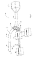
- Fig. 1 shows a pitot tube 10 comprising a tube wall 12 having an outer portion 14a configured to protrude outside a body of a vehicle (shown in Fig. 5 ), such an aircraft, and an inner portion 14b configured to be mounted inside the body of the vehicle.
- the tube 10 further includes a measuring box 15 fitted at the end of the inner portion 14b and configured with one or more measuring instruments for measuring pressure, fluid flow velocity, slide slip angle etc.
- the outer portion 14a can be mounted on the vehicle such that air flow in the direction opposite to the direction of displacement of the vehicle can enter the inside of the tube 10 towards the measuring box 15, where various parameters thereof can be detected and measured.
- the tube can be mounted at an angle with respect to the direction of the movement of the vehicle, for example and aircraft, such that the slide slip angle of the aircraft can be measured.
- the pitot tube 10 further includes a heating arrangement 20 for generating heat for heating thereby at least a portion of the tube wall 12, for example the outer portion 14a so as to prevent the tube from becoming clogged with ice.
- the heating arrangement 20 comprising a radiation source, such as an electromagnetic radiation source (EMR) configured to emit radiation.
- EMR electromagnetic radiation source
- the radiation can be light which is configured to generate heat, such as light in the IR spectrum.
- the light is emitted into a radiation conveying portion which can be mounted over the portion of the tube wall 12 to be heated.
- the conveying portion is configured to transmit the light to a radiation absorbing surface which absorbs the electromagnetic radiation (EMR) and generates heat thereby.
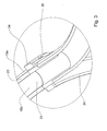
- the outer portion 14a of the tube wall 12 defines an outer surface 16a and an inner surface 16b, such that the radiation conveying portion is disposed therebetween.
- the conveying portion constitutes the entire outer portion 14a, and includes a transparent or translucent wall 22, such that light can be transmitted therethrough.
- the transparent wall 22 according to this example includes a radiation absorbing surface 24 defined on the inner surface 16b thereof such that light rays impinging thereon are absorbed by the radiation absorbing surface, and heat is generated thereby.
- the radiation absorbing surface 24 can be a coating disposed on at least a portion of the inner surface 16b, such which is sensitive to the light radiated through the transparent wall 22. Heating of the inner surface 16b of the outer portion 14a precludes ice accumulation thereon and prevents clogging of the tube 10.
- the coating can be made of a electromagnetic radiation sensitive material, or a color configured to absorb a certain light radiation spectrum.
- a light source 35 can be coupled to the radiation conveying portion, i.e. to the transparent wall 22, so as to allow light to be transmitted therethrough toward the absorbing surface 24. It is appreciated that the light source can be configured to emit light directly on the absorbing surface 24, however in order to allow mounting the light source further from the absorbing surface, a conveying portion (such as the transparent wall 22 of the present example) can be provided.
- the light transmitted through the transparent wall 22 is configured to travel therethrough by total internal reflection, such that at least some of the light is reflected by the outer surface 16a back inside the transparent wall and towards the absorbing surface 24 defined on the inner surface 16b.
- the absorbing surface 24 is configured to absorb at least a portion of the light impinging thereon, other portions of the light can be configured to be reflected back to the inside of the transparent wall 22 and towards the outer surface 16a, where the light is reflected back to other locations of the absorbing surface along the tube 10.
- a single light source can be utilized for emitting light to be absorbed by multi locations on the absorbing surface defined along the inner surface of the tube.
- the absorbing surface 24 can be defined along the entire inner surface 16b of the outer portion 14a of the tube 10, covering substantially the entire inner circumference thereof, thus providing heat to the entire inner surface of the outer potion 14a.
- the absorbing surface 24 can be in the form of a plurality of surfaces defined along portions of the outer or inner portions of the tube 10 for example as strips along the inner surface 16b, or as a plurality of rings defined about the inner circumference of the tube 10. The locations of the absorbing surfaces can be determined such that the entire inner surface 16b is heated to the extent which precludes accumulation of ice therein.
- the absorbing surface 24 can be defined inside the transparent wall 22, integrated therein between the inner surface 16b and the outer surface 16a. Accordingly light impinging on the absorbing surface 24 generates heat which is conducted to the inner surface 16b thereby preventing ice accumulation thereon.
- coupling the light source to the transparent wall 22 can be carried out by utilizing one or more optical fibers 30 for transmission of the light into the wall.
- the optical fibers 30 can be coupled on one end thereof to the light source, such as a laser diode integrated in a driver box 32, and on the other end thereof to a coupler 34.
- the coupler 34 can be a ring coupler disposed between the inner portion 14b and the outer portion 14a of the tube 10, however at a location such that it is disposed inside the body of the aircraft when the tube is mounted thereon. This way, the coupler 34 and the optical fibers 30 are not exposed to the winds and rain outside the aircraft.
- the coupler 34 is configured to receive light rays from each of the optical fibers and to direct these rays forward into the transparent wall 22. As explained hereinabove the rays can be directed such that total internal reflection occurs inside the transparent wall 22 and the rays are directed towards the absorbing surface 24.
- the driver box 32 can be configured to provide radiation at various frequencies or various pulse patterns thus allowing selecting the appropriate duty cycle.
- the driver box 32 is controlled by a controller 36 which can be configured to receive data regarding various parameters outside the vehicle, such as temperature, barometric pressure, humidity, etc. The data can be received from one or more sensors 38 mounted in an aperture on the body of the vehicle (best seen in Fig. 4 ), such that it is exposed to the ambient conditions outside the vehicle.
- the senor can be mounted inside the measuring box 15, or inside the tube 10.
- the transparent wall 22 can be provided with a thermometer integrated therein, such that when the temperature of the transparent wall drops below a predetermined threshold, the controller 36 can operate the driver box 32 to provide radiation into the transparent wall.
- the controller 36 and the driver box 32 can be integrated into a single module.
- the radiation source can be integrated inside the coupler 34 such that it can illuminate directly into the transparent wall 22.
- the driver box 32 according to this example can be coupled to the coupler 34 by electric wires providing signals from an electronic system inside the driver box 32 for determining the duty cycle and period of the radiation source.
- the wall 7 of the body extends between the outer portion 14a and the inner portion 14b such that the inner portion of the tube, the coupler 34, the driver box 32, and the optical fibers 30 are disposed inside the body of the vehicle, while the outer portion is disposed outside thereof.
- the tube is disposed such that air flow can enter the inside of the tube through the outer portion 14a and the inner portion 14b towards the measuring box 15.
- the temperature of the inside surface 16b of the tube 10 is maintained at a predetermined temperature thus preventing humidity and ice in the airflow from accumulating on the inner surface 16b.
- the temperature is maintained by the heat generated by the absorbing surface 24 which receives EM radiation through the transparent wall 22.
- the intensity or the frequency of the EM radiation directed towards the absorbing surface 24 can be selected in accordance with the required temperature.
- the EMR source can be set to constantly emit radiation, or to emit radiation when the temperature of the inner surface 16b drops below a preset threshold.
- Checking the temperature of the inner surface 16b can be carried out by detecting the temperature of the airflow, or for example by means of the sensor 38.
- the tube 50 is substantially the same as the tube 10 of Figs. 1 to 4 and includes an outer portion 52a for mounting outside the body of the vehicle, and an inner portion 52b for mounting inside the body of the vehicle.
- the tube 50 further includes a measuring box 53 mounted at the end of the inner portion 52b and a heating arrangement in the form of a radiation source for emitting electromagnetic radiation for heating the tube.
- both the outer portion 52a and the inner portion 52b of the tube can be made of any suitable material such as metal.
- the outer portion 52a however is configured with an EMR conveying portion such as a transparent shell 58, covering portions of the outer potion 52a.
- the transparent shell 58 can be configured to cover the entire or portions of the outer surface 56a of the outer portion 52a, such a sleeve mounted on the outer portion. According to another example, the transparent shell 58 can be configured to cover the entire or portions of the inner surface 56b of the outer portion 52a, such a sleeve mounted inside the outer portion.
- the transparent shell 58 includes an absorbing surface 60 defined therein for example on the inside surface 59a thereof, such that when the shell is disposed over the outer portion 52a the absorbing surface 60 is disposed adjacent the outer surface 56a of the outer portion.
- the absorbing surface 60 receives radiation transmitted through the transparent shell 58 and generates heat thereby for heating the outer portion 52a of the tube 50.
- the absorbing surface can be defined inside the transparent shell 58, and be configured to generate heat thereby heating the transparent shell and providing heat by conduction to the outer portion 52a.
- the absorbing surface 60 can be defined on the outer surface 56a of the outer portion 52a, and be configured to receive radiation transmitted through the transparent shell 58 and to generate heat thereby for heating the outer portion 52a. It is appreciated that according this example the transparent shell 58 need not be affixed to the outer portion 52a, rather the transparent shell can be disposed over the outer portion with a gap therebetween having air, vacuum, or fluids. The transparent shell 58 can be configured to emit the light transmitted therethrough towards the absorbing surface 60 through the gap therebetween.
- the transparent shell 58 need not be disposed over the entire outer portion 52a, rather it can be a radiation conveying element disposed over portions of the outer portion, for example over areas where ice is likely to accumulate, such as areas with curves, ridges or grooves.
- the radiation conveying portion can be configured to scatter the radiation transmitted therethrough in the direction towards the absorbing surface 60.
- the radiation conveying portion can be a relatively thin element, however configured to scatter the radiation over a relatively large area of the absorbing surface. Such arrangement can be achieved by utilizing various optical instruments, as known.
- the radiation conveying portion can be a transparent pipe section having a radius smaller than the inner radius of the outer portion 52a such that it can be mounted inside the outer portion 52a.
- the transparent pipe section is configured to allow incoming airflow towards to inner portion 52b and the measuring box.
- the absorbing surface 60 can be disposed on the inner surface of the transparent pipe section, such that radiation through the transparent pipe section impinges thereon and heat is generated, thereby precluding accumulation of ice on the inner surface of the pipe section.
- the absorbing surface can be disposed inside the transparent pipe section such that when radiation impinges thereon, heat is generated thereby heating the entire pipe section.
- the transparent pipe can be disposed inside the outer portion, such that the entire inner surface thereof is covered.
- the transparent pipe can be disposed only over certain areas of the inside surface of the outer portion, for example areas in which ice is likely to accumulate.
- the transparent pipe thus can be in the form of a transparent ring, or other transparent element configured to be mounted on an area of the inner surface of the outer portion of the tube.
- the transparent pipe according to this example does not cover the entire inner surface of the outer portion, the absorbing surface can be configured to generate enough heat to maintain the temperature of the entire inner surface.
- the radiation such as the light can be transmitted from the light source to the transparent ring by means of optical fibers extending from the light source through the outer portion of the tube and towards the transparent ring the transparent element or any other radiation conveying portion.
Landscapes
- Engineering & Computer Science (AREA)
- Aviation & Aerospace Engineering (AREA)
- Physics & Mathematics (AREA)
- General Physics & Mathematics (AREA)
- Length Measuring Devices By Optical Means (AREA)
- Heat Sensitive Colour Forming Recording (AREA)
Abstract
Description
- The present disclosed subject matter relates to a pitot tube in general and in particular to a heating system for pitot tubes.
- A Pitot tube is a pressure measurement instrument utilized for measuring fluid flow velocity in vehicles which do not run on wheels, for example determining the airspeed of an aircraft, water speed of a boat, and to measure liquid. In addition the pitot tube is utilized for measuring air and gas velocities in industrial applications.
- The pitot tube includes a tube extending outside the vehicle and having an opening in the direction of the movement of the vehicle, such that fluid flow in the opposite direction enters the tube. Measuring instruments are mounted at the end of the tube configured for measuring the fluid flow velocity by converting the kinetic energy in the fluid flow into potential energy. According to another example the tube can be mounted at an angle with respect to the direction of the movement of the vehicle, for example an aircraft, such that the slide slip angle of the aircraft can be measured.
- Pitot tubes on aircraft commonly have heating elements called pitot heat to prevent the tube from becoming clogged with ice, and thus prevent the failure of the pitot tube. The heating element extends through the tube and maintains the temperature thereof at a predetermined temperature.
- There is provided according to one aspect of the presently disclosed subject matter a pitot tube having a tube wall and a heating arrangement for generating heat for heating thereby at least a portion of the tube wall to prevent the tube from becoming clogged with ice. The heating arrangement includes a radiation absorbing surface configured for absorbing electromagnetic radiation (EMR) and generating the heat. At least one radiation conveying portion is provided for receiving EMR from an EMR source and conveying it to the radiation absorbing surface.
- As used hereinafter, the term 'transparent' includes any material which is transparent, partially transparent, translucent, and material which is transparent to a certain spectrum of electromagnetic radiation, or transparent to a certain light spectrum. The radiation absorbing surface can be a coating.
The coating can be disposed over a surface of the pitot tube, or over a surface of the radiation conveying portion. The coating can be paint and/or can be made of a light sensitive material.
The radiation absorbing surface can be integrated within the radiation conveying portion.
The electromagnetic radiation can be light radiation and the light radiation can be in the IR spectrum.
According to an example the tube wall can have an outer surface and an inner surface and the radiation conveying portion can be disposed therebetween. The outer surface can be the outer surface of the radiation conveying portion and the inner surface can be the inner surface of the radiation conveying portion. According to an example, the outer portion can constitute the radiation conveying portion. The outer portion can be a wall configured for conveying the EMR and the radiation absorbing surface can be disposed on the inner surface. Alternatively, the radiation absorbing surface can be integrated within the wall.
The radiation conveying portion can be at least partially made of a transparent material. According to an example of the presently disclosed subject matter the radiation conveying portion can be a shell mounted over the tube wall. The tube wall can include and outer portion and an inner portion and the shell can be configured to cover the outer portion. The radiation absorbing surface can be disposed on an inner surface of the shell. Alternatively, the radiation absorbing surface can be disposed adjacent the outer surface of the outer portion.
The radiation absorbing surface can be integrated within the shell.
The radiation conveying portion can be a pipe segment mounted inside the tube wall. The tube wall includes an outer portion and an inner portion and wherein the pipe segment can be configured to cover the inner portion. The radiation absorbing surface can be disposed on an inner surface of the pipe segment or the radiation absorbing surface can be integrated within the pipe segment. Alternatively, the radiation absorbing surface can be disposed on an outer surface of the pipe segment. The radiation absorbing surface can be disposed adjacent the inner surface of the outer portion.
The radiation conveying portion can be at least one pipe ring disposed on a portion of the inside surface of the tube wall.
The EMR source can be configured to emit the EMR in more than one frequency and can be configured to emit the EMR in various duty cycle modes selected in accordance with the ambient conditions. - According to another aspect of the presently disclosed subject matter there is provided a method for heating a pitot tube having a tube wall, the method comprising coupling to the tube wall a radiation absorbing surface configured for absorbing electromagnetic radiation and heating thereby the tube wall; providing an electromagnetic radiation source; and coupling a radiation conveying portion to the electromagnetic radiation source for receiving electromagnetic radiation therefrom and conveying it to the radiation absorbing surface.
- According to a further aspect of the presently disclosed subject matter there is provided a heating arrangement for heating a pitot tube having a tube wall, the heating arrangement comprising; a radiation absorbing surface configured for absorbing electromagnetic radiation (EMR) and generating thereby heat, the radiation absorbing surface being configured for coupling thereof to the tube wall; an electromagnetic radiation source configured for emitting the EMR; and a radiation conveying portion coupled to the EMR for receiving electromagnetic radiation therefrom and conveying thereof to the radiation absorbing surface.
The radiation conveying portion can be a shell configured to be mounted over the tube wall or the radiation conveying portion can be a pipe segment configured to be mounted inside the tube wall.
The EMR source can be configured to emit the EMR in more than one frequency and can be configured to emit the EMR in various duty cycle modes selected in accordance with the ambient conditions. - In order to better understand the subject matter that is disclosed herein and to exemplify how it may be carried out in practice, embodiments will now be described, by way of non-limiting example only, with reference to the accompanying drawings, in which:
-
Fig. 1 is an isometric view of a pitot tube according to an example of the presently discloses subject matter; -
Fig. 2 is a side sectional view of the pitot tube ofFig. 1 ; -
Fig. 3 is an enlarged view of a coupler according to an example of the presently disclosed subject matter, for mounting on the pitot tube; -
Fig. 4 is an isometric view of the pitot tube ofFig. 1 mounted in a wall segment of a vehicle; -
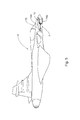
Fig. 5 is an isometric view of an aircraft having the pitot tube ofFig. 1 mounted therein; -
Fig. 6 is an exploded view of a pitot tube according to another example of the presently disclosed subject matter; and -
Fig. 7 is a side sectional view of the pitot tube ofFig. 6 . -
Fig. 1 shows apitot tube 10 comprising atube wall 12 having anouter portion 14a configured to protrude outside a body of a vehicle (shown inFig. 5 ), such an aircraft, and aninner portion 14b configured to be mounted inside the body of the vehicle. Thetube 10 further includes ameasuring box 15 fitted at the end of theinner portion 14b and configured with one or more measuring instruments for measuring pressure, fluid flow velocity, slide slip angle etc. Theouter portion 14a can be mounted on the vehicle such that air flow in the direction opposite to the direction of displacement of the vehicle can enter the inside of thetube 10 towards themeasuring box 15, where various parameters thereof can be detected and measured. Alternatively, the tube can be mounted at an angle with respect to the direction of the movement of the vehicle, for example and aircraft, such that the slide slip angle of the aircraft can be measured. - The
pitot tube 10 further includes aheating arrangement 20 for generating heat for heating thereby at least a portion of thetube wall 12, for example theouter portion 14a so as to prevent the tube from becoming clogged with ice. Theheating arrangement 20 comprising a radiation source, such as an electromagnetic radiation source (EMR) configured to emit radiation. The radiation can be light which is configured to generate heat, such as light in the IR spectrum. The light is emitted into a radiation conveying portion which can be mounted over the portion of thetube wall 12 to be heated. The conveying portion is configured to transmit the light to a radiation absorbing surface which absorbs the electromagnetic radiation (EMR) and generates heat thereby. - As shown in
Fig. 2 , theouter portion 14a of thetube wall 12 defines anouter surface 16a and aninner surface 16b, such that the radiation conveying portion is disposed therebetween. According to the illustrated example the conveying portion constitutes the entireouter portion 14a, and includes a transparent ortranslucent wall 22, such that light can be transmitted therethrough. Thetransparent wall 22 according to this example includes aradiation absorbing surface 24 defined on theinner surface 16b thereof such that light rays impinging thereon are absorbed by the radiation absorbing surface, and heat is generated thereby. Theradiation absorbing surface 24 can be a coating disposed on at least a portion of theinner surface 16b, such which is sensitive to the light radiated through thetransparent wall 22. Heating of theinner surface 16b of theouter portion 14a precludes ice accumulation thereon and prevents clogging of thetube 10. The coating can be made of a electromagnetic radiation sensitive material, or a color configured to absorb a certain light radiation spectrum. - A light source 35 can be coupled to the radiation conveying portion, i.e. to the
transparent wall 22, so as to allow light to be transmitted therethrough toward the absorbingsurface 24. It is appreciated that the light source can be configured to emit light directly on the absorbingsurface 24, however in order to allow mounting the light source further from the absorbing surface, a conveying portion (such as thetransparent wall 22 of the present example) can be provided. - According to an example, the light transmitted through the
transparent wall 22 is configured to travel therethrough by total internal reflection, such that at least some of the light is reflected by theouter surface 16a back inside the transparent wall and towards the absorbingsurface 24 defined on theinner surface 16b. It is noted that while the absorbingsurface 24 is configured to absorb at least a portion of the light impinging thereon, other portions of the light can be configured to be reflected back to the inside of thetransparent wall 22 and towards theouter surface 16a, where the light is reflected back to other locations of the absorbing surface along thetube 10. This way, a single light source can be utilized for emitting light to be absorbed by multi locations on the absorbing surface defined along the inner surface of the tube. - According to an example the absorbing
surface 24 can be defined along the entireinner surface 16b of theouter portion 14a of thetube 10, covering substantially the entire inner circumference thereof, thus providing heat to the entire inner surface of theouter potion 14a. However, according to other examples the absorbingsurface 24 can be in the form of a plurality of surfaces defined along portions of the outer or inner portions of thetube 10 for example as strips along theinner surface 16b, or as a plurality of rings defined about the inner circumference of thetube 10. The locations of the absorbing surfaces can be determined such that the entireinner surface 16b is heated to the extent which precludes accumulation of ice therein. - According to a further example the absorbing
surface 24 can be defined inside thetransparent wall 22, integrated therein between theinner surface 16b and theouter surface 16a. Accordingly light impinging on the absorbingsurface 24 generates heat which is conducted to theinner surface 16b thereby preventing ice accumulation thereon. - According to an example, coupling the light source to the
transparent wall 22 can be carried out by utilizing one or moreoptical fibers 30 for transmission of the light into the wall. Theoptical fibers 30 can be coupled on one end thereof to the light source, such as a laser diode integrated in adriver box 32, and on the other end thereof to acoupler 34. Thecoupler 34 can be a ring coupler disposed between theinner portion 14b and theouter portion 14a of thetube 10, however at a location such that it is disposed inside the body of the aircraft when the tube is mounted thereon. This way, thecoupler 34 and theoptical fibers 30 are not exposed to the winds and rain outside the aircraft. - The
coupler 34 is configured to receive light rays from each of the optical fibers and to direct these rays forward into thetransparent wall 22. As explained hereinabove the rays can be directed such that total internal reflection occurs inside thetransparent wall 22 and the rays are directed towards the absorbingsurface 24. Thedriver box 32 can be configured to provide radiation at various frequencies or various pulse patterns thus allowing selecting the appropriate duty cycle. Thedriver box 32 is controlled by acontroller 36 which can be configured to receive data regarding various parameters outside the vehicle, such as temperature, barometric pressure, humidity, etc. The data can be received from one ormore sensors 38 mounted in an aperture on the body of the vehicle (best seen inFig. 4 ), such that it is exposed to the ambient conditions outside the vehicle. - Alternatively, the sensor can be mounted inside the measuring
box 15, or inside thetube 10. For example, thetransparent wall 22 can be provided with a thermometer integrated therein, such that when the temperature of the transparent wall drops below a predetermined threshold, thecontroller 36 can operate thedriver box 32 to provide radiation into the transparent wall. It is appreciated that thecontroller 36 and thedriver box 32 can be integrated into a single module. In addition, according to another example, the radiation source can be integrated inside thecoupler 34 such that it can illuminate directly into thetransparent wall 22. Thedriver box 32 according to this example can be coupled to thecoupler 34 by electric wires providing signals from an electronic system inside thedriver box 32 for determining the duty cycle and period of the radiation source. - As shown in
Figs. 4 and5 when thetube 10 is mounted inside a body of avehicle 5 thewall 7 of the body extends between theouter portion 14a and theinner portion 14b such that the inner portion of the tube, thecoupler 34, thedriver box 32, and theoptical fibers 30 are disposed inside the body of the vehicle, while the outer portion is disposed outside thereof. This way, the tube is disposed such that air flow can enter the inside of the tube through theouter portion 14a and theinner portion 14b towards the measuringbox 15. The temperature of theinside surface 16b of thetube 10, is maintained at a predetermined temperature thus preventing humidity and ice in the airflow from accumulating on theinner surface 16b. The temperature is maintained by the heat generated by the absorbingsurface 24 which receives EM radiation through thetransparent wall 22. - It is appreciated that the intensity or the frequency of the EM radiation directed towards the absorbing
surface 24 can be selected in accordance with the required temperature. Thus, the EMR source can be set to constantly emit radiation, or to emit radiation when the temperature of theinner surface 16b drops below a preset threshold. - Checking the temperature of the
inner surface 16b can be carried out by detecting the temperature of the airflow, or for example by means of thesensor 38. - Reference is now made to
Figs. 6 and7 , showing apitot tube 50 according to another example of the presently disclosed subject matter. Thetube 50 is substantially the same as thetube 10 ofFigs. 1 to 4 and includes anouter portion 52a for mounting outside the body of the vehicle, and aninner portion 52b for mounting inside the body of the vehicle. Thetube 50 further includes ameasuring box 53 mounted at the end of theinner portion 52b and a heating arrangement in the form of a radiation source for emitting electromagnetic radiation for heating the tube. According to this example both theouter portion 52a and theinner portion 52b of the tube can be made of any suitable material such as metal. Theouter portion 52a however is configured with an EMR conveying portion such as atransparent shell 58, covering portions of theouter potion 52a. Thetransparent shell 58 can be configured to cover the entire or portions of theouter surface 56a of theouter portion 52a, such a sleeve mounted on the outer portion. According to another example, thetransparent shell 58 can be configured to cover the entire or portions of theinner surface 56b of theouter portion 52a, such a sleeve mounted inside the outer portion. - According to the illustrated example, the
transparent shell 58 includes an absorbingsurface 60 defined therein for example on theinside surface 59a thereof, such that when the shell is disposed over theouter portion 52a the absorbingsurface 60 is disposed adjacent theouter surface 56a of the outer portion. This way, the absorbingsurface 60 receives radiation transmitted through thetransparent shell 58 and generates heat thereby for heating theouter portion 52a of thetube 50. It is appreciated that the absorbing surface can be defined inside thetransparent shell 58, and be configured to generate heat thereby heating the transparent shell and providing heat by conduction to theouter portion 52a. Alternatively, the absorbingsurface 60 can be defined on theouter surface 56a of theouter portion 52a, and be configured to receive radiation transmitted through thetransparent shell 58 and to generate heat thereby for heating theouter portion 52a. It is appreciated that according this example thetransparent shell 58 need not be affixed to theouter portion 52a, rather the transparent shell can be disposed over the outer portion with a gap therebetween having air, vacuum, or fluids. Thetransparent shell 58 can be configured to emit the light transmitted therethrough towards the absorbingsurface 60 through the gap therebetween. - It is further appreciated that the
transparent shell 58 need not be disposed over the entireouter portion 52a, rather it can be a radiation conveying element disposed over portions of the outer portion, for example over areas where ice is likely to accumulate, such as areas with curves, ridges or grooves. In addition, the radiation conveying portion can be configured to scatter the radiation transmitted therethrough in the direction towards the absorbingsurface 60. Accordingly, the radiation conveying portion can be a relatively thin element, however configured to scatter the radiation over a relatively large area of the absorbing surface. Such arrangement can be achieved by utilizing various optical instruments, as known. - According to a further example (not shown) the radiation conveying portion can be a transparent pipe section having a radius smaller than the inner radius of the
outer portion 52a such that it can be mounted inside theouter portion 52a. The transparent pipe section is configured to allow incoming airflow towards toinner portion 52b and the measuring box. The absorbingsurface 60, according to this example, can be disposed on the inner surface of the transparent pipe section, such that radiation through the transparent pipe section impinges thereon and heat is generated, thereby precluding accumulation of ice on the inner surface of the pipe section. - Alternatively, the absorbing surface can be disposed inside the transparent pipe section such that when radiation impinges thereon, heat is generated thereby heating the entire pipe section.
- As in the previous examples, the transparent pipe can be disposed inside the outer portion, such that the entire inner surface thereof is covered. However, according to other examples, the transparent pipe can be disposed only over certain areas of the inside surface of the outer portion, for example areas in which ice is likely to accumulate. The transparent pipe thus can be in the form of a transparent ring, or other transparent element configured to be mounted on an area of the inner surface of the outer portion of the tube.
- Although the transparent pipe according to this example does not cover the entire inner surface of the outer portion, the absorbing surface can be configured to generate enough heat to maintain the temperature of the entire inner surface. It is appreciated that according to this example the radiation, such as the light can be transmitted from the light source to the transparent ring by means of optical fibers extending from the light source through the outer portion of the tube and towards the transparent ring the transparent element or any other radiation conveying portion.
- Those skilled in the art to which the presently disclosed subject matter pertains will readily appreciate that numerous changes, variations, and modifications can be made without departing from the scope of the invention, mutatis mutandis.
Claims (15)
- A pitot tube (10) having a tube wall (12) and a heating arrangement (20) for generating heat for heating thereby at least a portion of said tube wall (12) to prevent the tube from becoming clogged with ice; the heating arrangement (20) comprising a radiation absorbing surface (24; 60) configured for absorbing electromagnetic radiation (EMR) and generating said heat; and at least one radiation conveying portion for receiving EMR from an EMR source (35) and conveying it to said radiation absorbing surface (24; 60).
- The pitot tube (10) according to claim 1 wherein the radiation absorbing surface (24; 60) is a coating disposed over a surface of the pitot tube (10), wherein said coating is made of a light sensitive material and wherein said electromagnetic radiation is light radiation.
- The pitot tube (10) according to claim 1 wherein said tube wall (12) having an outer surface and an inner surface and wherein said radiation conveying portion (30) disposed therebetween and
wherein said outer surface (16a; 56a) is the outer surface of said radiation conveying portion (30) and said inner surface (16b; 56b) is the inner surface of said radiation conveying portion (30). - The pitot tube (10) according to claim 3 wherein said tube wall (12) includes an outer portion (14a; 52a) and inner portion (14b; 52b) and wherein said outer portion (14a; 52a) constitutes said radiation conveying portion (30).
- The pitot tube (10) according to claim 3 wherein said outer portion (14a; 52a) is a wall configured for conveying said EMR and said radiation absorbing surface (24; 60) is integrated within said wall.
- The pitot tube (10) according to any one of the previous claims wherein said radiation conveying portion (30) is at least partially made of a transparent material.
- The pitot tube (10) according to any one of claims 1 to 2 wherein said radiation conveying portion is a shell (58) mounted over said tube wall (12) and said tube wall (12) includes and outer portion (14a; 52a) and an inner portion (14b; 52b) and wherein said shell (58) is configured to cover said outer portion (14a; 52a).
- The pitot tube (10) according to claim 7 wherein said radiation absorbing surface is disposed on an inner surface (59a) of said shell (58).
- The pitot tube (10) according to claim 8 wherein said radiation absorbing surface (24; 60) is disposed adjacent said outer surface (16a; 56a) of said outer portion (14a; 52a).
- The pitot tube (10) according to claim 7 wherein said radiation absorbing surface (24; 60) is integrated within said shell (58).
- The pitot tube (10) according to any one of claims 1 to 2 wherein said radiation conveying portion is a pipe segment mounted inside said tube wall (12).
- The pitot tube (10) according to claim 11 wherein said tube wall (12) includes an outer portion (14a; 52a) and an inner portion (14b; 52b) and wherein said pipe segment is configured to cover said inner portion (14b; 52b).
- The pitot tube (10) according to claim 11 wherein said radiation absorbing surface (24; 60) is disposed on an outer surface of said pipe segment.
- A heating arrangement (20) for heating a pitot tube (10) having a tube wall (12), the heating arrangement (20) comprising;
a radiation absorbing surface (24; 60) configured for absorbing electromagnetic radiation (EMR) and generating thereby heat, said radiation absorbing surface (24; 60) being configured for coupling to the tube wall (12);
an electromagnetic radiation source (35) configured for emitting said EMR; and
a radiation conveying portion (30) coupled to said EMR source (35) for receiving electromagnetic radiation therefrom and conveying the electromagnetic radiation to said radiation absorbing surface (24; 60). - The heating arrangement according to claim 14 wherein said EMR source (35) is configured to emit said EMR in more than one frequency and wherein said EMR source (35) is configured to emit said EMR in various duty cycle modes selected in accordance with the ambient conditions.
Applications Claiming Priority (1)
| Application Number | Priority Date | Filing Date | Title |
|---|---|---|---|
| IL228493A IL228493B (en) | 2013-09-17 | 2013-09-17 | Pitot tube |
Publications (1)
| Publication Number | Publication Date |
|---|---|
| EP2848945A1 true EP2848945A1 (en) | 2015-03-18 |
Family
ID=50436393
Family Applications (1)
| Application Number | Title | Priority Date | Filing Date |
|---|---|---|---|
| EP14185234.3A Withdrawn EP2848945A1 (en) | 2013-09-17 | 2014-09-17 | Pitot tube |
Country Status (3)
| Country | Link |
|---|---|
| US (1) | US9726688B2 (en) |
| EP (1) | EP2848945A1 (en) |
| IL (1) | IL228493B (en) |
Cited By (1)
| Publication number | Priority date | Publication date | Assignee | Title |
|---|---|---|---|---|
| EP3543710A3 (en) * | 2018-03-23 | 2020-01-15 | Rosemount Aerospace Inc. | Power efficient heater control of air data sensor |
Families Citing this family (1)
| Publication number | Priority date | Publication date | Assignee | Title |
|---|---|---|---|---|
| KR101799161B1 (en) * | 2015-12-09 | 2017-11-17 | 한국항공우주연구원 | Pitot tube with inner slope |
Citations (5)
| Publication number | Priority date | Publication date | Assignee | Title |
|---|---|---|---|---|
| US2229740A (en) * | 1939-03-11 | 1941-01-28 | Helmore William | Air speed indicator |
| US2681409A (en) * | 1949-11-19 | 1954-06-15 | North American Aviation Inc | Condensate removing apparatus |
| US4593533A (en) * | 1974-12-05 | 1986-06-10 | Alsenz Richard H | Method and apparatus for detecting and controlling the formation of ice or frost |
| US6070475A (en) * | 1997-10-15 | 2000-06-06 | Rosemont Aerospace Inc. | Air data probe with heater means within wall |
| EP2273275A1 (en) * | 2009-07-09 | 2011-01-12 | Lutz Nolte | Pressure Probe |
Family Cites Families (2)
| Publication number | Priority date | Publication date | Assignee | Title |
|---|---|---|---|---|
| DE4403067C1 (en) | 1994-02-02 | 1995-04-06 | Deutsche Aerospace Airbus | Device for keeping liquid pipelines, which are open at one end, free of ice |
| US20100116806A1 (en) | 2007-05-08 | 2010-05-13 | Honeywell International Inc. | Automated heating system for ports susceptible to icing |
-
2013
- 2013-09-17 IL IL228493A patent/IL228493B/en active IP Right Grant
-
2014
- 2014-09-15 US US14/486,341 patent/US9726688B2/en active Active
- 2014-09-17 EP EP14185234.3A patent/EP2848945A1/en not_active Withdrawn
Patent Citations (5)
| Publication number | Priority date | Publication date | Assignee | Title |
|---|---|---|---|---|
| US2229740A (en) * | 1939-03-11 | 1941-01-28 | Helmore William | Air speed indicator |
| US2681409A (en) * | 1949-11-19 | 1954-06-15 | North American Aviation Inc | Condensate removing apparatus |
| US4593533A (en) * | 1974-12-05 | 1986-06-10 | Alsenz Richard H | Method and apparatus for detecting and controlling the formation of ice or frost |
| US6070475A (en) * | 1997-10-15 | 2000-06-06 | Rosemont Aerospace Inc. | Air data probe with heater means within wall |
| EP2273275A1 (en) * | 2009-07-09 | 2011-01-12 | Lutz Nolte | Pressure Probe |
Cited By (2)
| Publication number | Priority date | Publication date | Assignee | Title |
|---|---|---|---|---|
| EP3543710A3 (en) * | 2018-03-23 | 2020-01-15 | Rosemount Aerospace Inc. | Power efficient heater control of air data sensor |
| US10716171B2 (en) | 2018-03-23 | 2020-07-14 | Rosemount Aerospace Inc. | Power efficient heater control of air data sensor |
Also Published As
| Publication number | Publication date |
|---|---|
| IL228493B (en) | 2019-02-28 |
| US20150075294A1 (en) | 2015-03-19 |
| US9726688B2 (en) | 2017-08-08 |
| IL228493A0 (en) | 2014-03-31 |
Similar Documents
| Publication | Publication Date | Title |
|---|---|---|
| US10351103B2 (en) | LIDAR device with heated cover useful for automated vehicles | |
| KR102527536B1 (en) | De-icing system for sensors | |
| SE534963C2 (en) | Dust indicator for a vacuum cleaner | |
| CN107371374B (en) | Straws, urea sensors, and selective catalytic reduction (SCR) systems | |
| JP2012066806A (en) | Sensor arrangement for acquiring state variable | |
| US9726688B2 (en) | Pitot tube and heating arrangement therefore | |
| US12391218B2 (en) | System for cleaning a sensor/transmitter of a motor vehicle | |
| US20100235117A1 (en) | Optical Gas Flow Meter | |
| JP6596399B2 (en) | Clearance measuring device and clearance control system | |
| CN110954900A (en) | Sealing member and vehicle sensor unit | |
| CN110073201B (en) | Integrated Rain and Solar Radiation Sensing Module | |
| US6641301B2 (en) | Radiation detector with passive air purge and reduced noise | |
| WO2015146152A1 (en) | Integrated device | |
| US20220003844A1 (en) | Lidar device | |
| US6513971B2 (en) | Heatable member and temperature monitor therefor | |
| EP2273275A1 (en) | Pressure Probe | |
| CN104995522A (en) | A wind turbine component having an optical fibre wind sensor | |
| CN107750341A (en) | Optical triangulation sensors for range measurement | |
| WO2011003963A2 (en) | Pressure probe | |
| US11781896B2 (en) | Electro-optic sensor | |
| US20150117490A1 (en) | System and method for remote temperature measurements in a harsh environment | |
| EP3099576A1 (en) | Ice detecting apparatus | |
| EP3674674B1 (en) | Flame detector | |
| EP1391720A1 (en) | Emissivity probe | |
| US10024722B2 (en) | Temperature detection device for a vehicle heater |
Legal Events
| Date | Code | Title | Description |
|---|---|---|---|
| PUAI | Public reference made under article 153(3) epc to a published international application that has entered the european phase |
Free format text: ORIGINAL CODE: 0009012 |
|
| 17P | Request for examination filed |
Effective date: 20140917 |
|
| AK | Designated contracting states |
Kind code of ref document: A1 Designated state(s): AL AT BE BG CH CY CZ DE DK EE ES FI FR GB GR HR HU IE IS IT LI LT LU LV MC MK MT NL NO PL PT RO RS SE SI SK SM TR |
|
| AX | Request for extension of the european patent |
Extension state: BA ME |
|
| R17P | Request for examination filed (corrected) |
Effective date: 20150914 |
|
| RBV | Designated contracting states (corrected) |
Designated state(s): AL AT BE BG CH CY CZ DE DK EE ES FI FR GB GR HR HU IE IS IT LI LT LU LV MC MK MT NL NO PL PT RO RS SE SI SK SM TR |
|
| STAA | Information on the status of an ep patent application or granted ep patent |
Free format text: STATUS: EXAMINATION IS IN PROGRESS |
|
| 17Q | First examination report despatched |
Effective date: 20190830 |
|
| RIC1 | Information provided on ipc code assigned before grant |
Ipc: G01P 5/165 20060101AFI20200417BHEP |
|
| STAA | Information on the status of an ep patent application or granted ep patent |
Free format text: STATUS: THE APPLICATION IS DEEMED TO BE WITHDRAWN |
|
| 18D | Application deemed to be withdrawn |
Effective date: 20200911 |