EP2848872B1 - Klimaanlage - Google Patents
Klimaanlage Download PDFInfo
- Publication number
- EP2848872B1 EP2848872B1 EP14184830.9A EP14184830A EP2848872B1 EP 2848872 B1 EP2848872 B1 EP 2848872B1 EP 14184830 A EP14184830 A EP 14184830A EP 2848872 B1 EP2848872 B1 EP 2848872B1
- Authority
- EP
- European Patent Office
- Prior art keywords
- door
- rack
- air conditioner
- panel
- connection member
- Prior art date
- Legal status (The legal status is an assumption and is not a legal conclusion. Google has not performed a legal analysis and makes no representation as to the accuracy of the status listed.)
- Active
Links
Images





Classifications
-
- F—MECHANICAL ENGINEERING; LIGHTING; HEATING; WEAPONS; BLASTING
- F24—HEATING; RANGES; VENTILATING
- F24F—AIR-CONDITIONING; AIR-HUMIDIFICATION; VENTILATION; USE OF AIR CURRENTS FOR SCREENING
- F24F1/00—Room units for air-conditioning, e.g. separate or self-contained units or units receiving primary air from a central station
-
- F—MECHANICAL ENGINEERING; LIGHTING; HEATING; WEAPONS; BLASTING
- F25—REFRIGERATION OR COOLING; COMBINED HEATING AND REFRIGERATION SYSTEMS; HEAT PUMP SYSTEMS; MANUFACTURE OR STORAGE OF ICE; LIQUEFACTION SOLIDIFICATION OF GASES
- F25D—REFRIGERATORS; COLD ROOMS; ICE-BOXES; COOLING OR FREEZING APPARATUS NOT OTHERWISE PROVIDED FOR
- F25D17/00—Arrangements for circulating cooling fluids; Arrangements for circulating gas, e.g. air, within refrigerated spaces
- F25D17/04—Arrangements for circulating cooling fluids; Arrangements for circulating gas, e.g. air, within refrigerated spaces for circulating air, e.g. by convection
-
- F—MECHANICAL ENGINEERING; LIGHTING; HEATING; WEAPONS; BLASTING
- F24—HEATING; RANGES; VENTILATING
- F24F—AIR-CONDITIONING; AIR-HUMIDIFICATION; VENTILATION; USE OF AIR CURRENTS FOR SCREENING
- F24F1/00—Room units for air-conditioning, e.g. separate or self-contained units or units receiving primary air from a central station
- F24F1/0007—Indoor units, e.g. fan coil units
- F24F1/0011—Indoor units, e.g. fan coil units characterised by air outlets
-
- F—MECHANICAL ENGINEERING; LIGHTING; HEATING; WEAPONS; BLASTING
- F24—HEATING; RANGES; VENTILATING
- F24F—AIR-CONDITIONING; AIR-HUMIDIFICATION; VENTILATION; USE OF AIR CURRENTS FOR SCREENING
- F24F1/00—Room units for air-conditioning, e.g. separate or self-contained units or units receiving primary air from a central station
- F24F1/0007—Indoor units, e.g. fan coil units
- F24F1/0043—Indoor units, e.g. fan coil units characterised by mounting arrangements
- F24F1/0057—Indoor units, e.g. fan coil units characterised by mounting arrangements mounted in or on a wall
-
- F—MECHANICAL ENGINEERING; LIGHTING; HEATING; WEAPONS; BLASTING
- F24—HEATING; RANGES; VENTILATING
- F24F—AIR-CONDITIONING; AIR-HUMIDIFICATION; VENTILATION; USE OF AIR CURRENTS FOR SCREENING
- F24F13/00—Details common to, or for air-conditioning, air-humidification, ventilation or use of air currents for screening
- F24F13/08—Air-flow control members, e.g. louvres, grilles, flaps or guide plates
- F24F13/10—Air-flow control members, e.g. louvres, grilles, flaps or guide plates movable, e.g. dampers
- F24F13/12—Air-flow control members, e.g. louvres, grilles, flaps or guide plates movable, e.g. dampers built up of sliding members
-
- F—MECHANICAL ENGINEERING; LIGHTING; HEATING; WEAPONS; BLASTING
- F24—HEATING; RANGES; VENTILATING
- F24F—AIR-CONDITIONING; AIR-HUMIDIFICATION; VENTILATION; USE OF AIR CURRENTS FOR SCREENING
- F24F13/00—Details common to, or for air-conditioning, air-humidification, ventilation or use of air currents for screening
- F24F13/20—Casings or covers
-
- F—MECHANICAL ENGINEERING; LIGHTING; HEATING; WEAPONS; BLASTING
- F25—REFRIGERATION OR COOLING; COMBINED HEATING AND REFRIGERATION SYSTEMS; HEAT PUMP SYSTEMS; MANUFACTURE OR STORAGE OF ICE; LIQUEFACTION SOLIDIFICATION OF GASES
- F25D—REFRIGERATORS; COLD ROOMS; ICE-BOXES; COOLING OR FREEZING APPARATUS NOT OTHERWISE PROVIDED FOR
- F25D23/00—General constructional features
- F25D23/006—General constructional features for mounting refrigerating machinery components
-
- F—MECHANICAL ENGINEERING; LIGHTING; HEATING; WEAPONS; BLASTING
- F24—HEATING; RANGES; VENTILATING
- F24F—AIR-CONDITIONING; AIR-HUMIDIFICATION; VENTILATION; USE OF AIR CURRENTS FOR SCREENING
- F24F13/00—Details common to, or for air-conditioning, air-humidification, ventilation or use of air currents for screening
- F24F13/08—Air-flow control members, e.g. louvres, grilles, flaps or guide plates
- F24F13/10—Air-flow control members, e.g. louvres, grilles, flaps or guide plates movable, e.g. dampers
- F24F13/14—Air-flow control members, e.g. louvres, grilles, flaps or guide plates movable, e.g. dampers built up of tilting members, e.g. louvre
- F24F13/1426—Air-flow control members, e.g. louvres, grilles, flaps or guide plates movable, e.g. dampers built up of tilting members, e.g. louvre characterised by actuating means
- F24F2013/1433—Air-flow control members, e.g. louvres, grilles, flaps or guide plates movable, e.g. dampers built up of tilting members, e.g. louvre characterised by actuating means with electric motors
-
- F—MECHANICAL ENGINEERING; LIGHTING; HEATING; WEAPONS; BLASTING
- F24—HEATING; RANGES; VENTILATING
- F24F—AIR-CONDITIONING; AIR-HUMIDIFICATION; VENTILATION; USE OF AIR CURRENTS FOR SCREENING
- F24F13/00—Details common to, or for air-conditioning, air-humidification, ventilation or use of air currents for screening
- F24F13/08—Air-flow control members, e.g. louvres, grilles, flaps or guide plates
- F24F13/10—Air-flow control members, e.g. louvres, grilles, flaps or guide plates movable, e.g. dampers
- F24F13/14—Air-flow control members, e.g. louvres, grilles, flaps or guide plates movable, e.g. dampers built up of tilting members, e.g. louvre
- F24F13/1426—Air-flow control members, e.g. louvres, grilles, flaps or guide plates movable, e.g. dampers built up of tilting members, e.g. louvre characterised by actuating means
- F24F2013/1446—Air-flow control members, e.g. louvres, grilles, flaps or guide plates movable, e.g. dampers built up of tilting members, e.g. louvre characterised by actuating means with gearings
-
- F—MECHANICAL ENGINEERING; LIGHTING; HEATING; WEAPONS; BLASTING
- F24—HEATING; RANGES; VENTILATING
- F24F—AIR-CONDITIONING; AIR-HUMIDIFICATION; VENTILATION; USE OF AIR CURRENTS FOR SCREENING
- F24F13/00—Details common to, or for air-conditioning, air-humidification, ventilation or use of air currents for screening
- F24F13/20—Casings or covers
- F24F2013/207—Casings or covers with control knobs; Mounting controlling members or control units therein
Definitions
- the present invention relates to an air conditioner, and more particularly, to an air conditioner including a door installed in order to provide a smooth appearance by hiding an outlet.
- an air conditioner is a device removing dust, and the like, present in the air while conditioning distribution of a temperature, humidity, an air current, and the like, appropriate for human activities using a cooling cycle.
- Main components configuring the cooling cycle include a compressor, a condenser, an evaporator, an expansion valve, a blowing fan, and the like.
- the air conditioner may be divided into a separation type air conditioner in which an indoor unit and an outdoor unit are separately installed and an integration type air conditioner in which an indoor unit and an outdoor unit are installed together in a single cabinet.
- the indoor unit of the separation type air conditioner includes a heat exchanger heat-exchanging air sucked into a panel and a blowing fan sucking air of the interior into the panel and again blowing the sucked air to the interior.
- a wall mounted air conditioner having a form in which it is fixedly installed on a wall among forms of the indoor units is formed so that an outlet is exposed on an appearance.
- a wall mounted air conditioner which is one type of air conditioners, installed in a way to be fixed to a wall is provided to have an outlet exposed on the appearance.
- a blade installed at the outlet simultaneously serves to open and close the outlet and to control a wind direction in a vertical direction. Since a predetermined distance should be maintained between the blade and peripheral components in order to drive the blade, even in the case in which the air conditioner is not operated, an outer line of the outlet is exposed to the outside.
- EP2031320 discloses an air conditioner that delivers a directed airflow.
- an air conditioner having a smooth appearance by completely hiding an outlet.
- an air conditioner having an entirely slim appearance using a door slid while having a changing curvature.
- the air conditioner may further include a driving device positioned at one side of an inner portion of the second panel part and providing power so that the door is slidable.
- the driving device may include a motor providing the power, a pinion having a shaft connected to the motor to thereby be rotated, and a rack engaged and moved with the pinion.
- One side of the rack and one side of the door may be coupled to each other while having the second panel part disposed therebetween so that the door is movable as the rack moves toward the lower panel.
- the rack may be extended in a length direction while having a curvature, and the door and the rack may have different curvatures.
- the door may have a curvature larger than that of the rack so that it is slid adjacently to the lower panel.
- the first and second panel parts may be formed as a curved surface so that the front panel protrudes so as to be convex with respect to the wall, and a portion at which the first and second panel parts are connected to each other may have a maximum spacing distance from the wall.
- One side of the first panel part may contact the wall, and one side of the second panel part may be spaced apart from the wall so that the lower panel is positioned.
- the air conditioner may further include a cover covering upper portions of the first and second panel parts, wherein the door is connected to the cover to cover a lower portion of the second panel part and the cover and the door have the same thickness so as to form a smooth surface.
- the air conditioner may further include a pair of side panels installed on both sides of the front panel and the lower panel, wherein the door includes side ribs formed on both sides thereof, the side ribs protruding so as to contact the pair of side panels.
- the pair of side panels may include side guides concavely formed on outer surfaces thereof along the movement trajectory, respectively, so that the door is stably movable, and the side ribs may include protrusions protruding toward the pair of side panels so as to be fitted into the side guides, respectively.
- the motor may be a step motor rotated by a predetermined angle depending on input pulses.
- the motor may be operated so as to be variably controlled in a relief section in which additional power is required while the door reciprocates.
- the outlet may be provided with a blade for changing a direction of discharged air.
- an air conditioner including: a front panel formed so as to be convex with respect to a wall and having an outlet disposed at a lower portion thereof; a door installed on a front surface of the front panel so as to open and close the outlet; and a driving device including a pinion rotatably installed in the front panel so that the door opens and closes the outlet while being slid and a rack engaged and moved with the pinion, wherein one side of the rack and one side of the door are connected to each other so that the lower portion of the front panel is positioned between the rack and the door.
- the driving device may include a case fixed in the front panel so as to form an appearance to protect the pinion and the rack positioned therein.
- the case may include an opening formed at one side thereof so that the rack is movable outwardly, and one side of the rack exposed through the opening may be connected to one side of the door.
- An inner portion of the case may be provided with a guide concavely formed along a movement path of the rack so that the rack is stably movable.
- the rack may include a sawtooth engaged with the pinion and rack ribs formed on both sides of the sawtooth, wherein the rack rib is inserted into the guide while having a gap in order to decrease contact friction with the guide.
- the guide may be formed in a partial section of the movement path of the rack in order to decrease contact friction between the rack and the guide.
- An inner surface of one side of the door may be provided with a protrusion, and one side of the rack may be coupled to the protrusion while being fitted into the protrusion so that the door is moved as the rack is moved.
- the protrusion may include a rib extended toward an opening, and the rack and the rib may be coupled to each other in a length direction of the rack.
- an air conditioner including: a body forming an appearance; an outlet formed at a lower portion of the body and discharging air; a door installed on a front surface of the body so as to open and close the outlet while being slid; a driving device providing power so that the door is slidable; and an auxiliary device installed so as to elastically bias the door upwardly.
- the driving device may include a rotating pinion and a rack engaged and moved with the pinion, and the auxiliary device may include a spring providing elastic force and a connection member connected to one side of the spring to thereby be moved.
- the driving device may include a case formed so that the auxiliary device is positioned therein, the case may include an opening formed at one side thereof so that the rack is movable outwardly, and one side of the rack exposed through the opening may be connected to one side of the door.
- One side of the spring may be fixed to one side of the case, and a side of the connection member opposite to the side of the connection member connected to the spring may be coupled to the rack so that the connection member is movable as the rack is moved.
- connection member may include protrusions formed at both sides thereof, and both sides of the case may be provided with auxiliary guides formed as an opening along an interworking section in which the connection member and the rack are coupled to each other and are moved, so that the protrusions are fitted thereinto and moved therealong.
- One side of the auxiliary guide may be provided with a bent fixing groove into which the protrusion is inserted, so that the connection member is separated from the rack and is fixed in the state in which the spring is expanded, in the case in which the rack is moved outwardly through the opening.
- the auxiliary guide may include a safety groove having the protrusion inserted thereinto by the rack and then returning the protrusion to the fixing groove so that the rack enters the connection member through the opening to thereby be coupled to the connection member, in the case in which the protrusion deviates from the fixing groove due to external impact, such that the connection member is moved by the elastic force.
- FIG. 1 is a diagram showing an air conditioner 1 according to an exemplary embodiment.
- the air conditioner 1 heat-exchanges high temperature air with a low temperature refrigerant using a cooling cycle including a compressor, a condenser, an expansion valve, and an evaporator and then supplies low temperature air to the interior.
- a cooling cycle including a compressor, a condenser, an expansion valve, and an evaporator and then supplies low temperature air to the interior.
- the compressor and the condenser are disposed in an outdoor unit of the air conditioner
- the expansion valve is disposed in any one of the indoor unit and the outdoor unit
- the evaporation is disposed in the indoor unit.
- the indoor unit is divided into a stand type indoor unit standing on a floor in order to cool or heat a relatively large indoor space and a wall mounted type indoor unit mounted on a wall in order to cool or heat a relatively small indoor space.
- the wall mounted type air conditioner 1 mounted on the wall includes a body provided with an inlet 3 and an outlet 5.
- the body includes a rear panel fixed to the wall and a front panel 10, a lower panel 12, and a pair of side panels 14 that enclose internal components such as a heat exchanger.
- the inlet may be disposed at an upper portion of the front panel 10.
- the inlet 3 may be always opened or be opened by an operation of the air conditioner 1.
- the inlet 3 may be provided with a filter device for removing foreign materials of air introduced from the interior into the air conditioner 1.
- the outlet 5 may be positioned at a lower portion of the front panel 10.
- the outlet 5 is a path through which the air introduced through the inlet 3 passes through the heat exchanger and is then discharged to the outside of the air conditioner 1.
- a blade 7 (See FIG. 2 ) may be installed on a front surface of the outlet 5 to control a direction in which the air is discharged.
- the air conditioner 1 has a structure in which both of the inlet 3 and the outlet 5 are installed in the front panel 10.
- An upper panel corresponding to the lower panel 12 is not present, and the front panel 10 has one side contacting the wall to protrude so as to be convex with respect to the wall.
- the front panel 10 may include a first panel part provided with the inlet 3 and a second panel part connected to a lower portion of the first panel part and provided with the outlet 5.
- the first and second panel parts of the front panel 10 may be formed as a curved surface, and a portion at which the first and second panel parts are connected to each other may have a maximum spacing distance from the wall.
- One side of the first panel part may contact the wall and the other side thereof may be connected to the second panel part.
- One side of the second panel part may be connected to the first panel part and the other side thereof may be connected to the lower panel 12.
- the second panel part may be spaced apart from the wall so that the lower panel 12 may be positioned between the second panel part and the wall.
- the pair of side panels 14 may be installed on both sides of the front panel 10 and the lower panel 12, respectively, to form the body of the air conditioner 1.
- the front panel 10 and the pair of side panels 14 may be formed integrally with each other.
- the first and second panel parts may have a cover 20 attached to front surfaces of upper portions thereof.
- the cover 20 may be manufactured by double injection and form an appearance of the air conditioner 1.
- the front surface of the second panel part may be provided with a door 100 for opening and closing the outlet 5.
- the door 100 may be connected to a lower portion of the cover 20 to cover the outlet 5 of the second panel part.
- the cover 20 and the door 100 may have the same thickness so that the air conditioner 1 may have a smooth surface.
- the door 100 may be manufactured by double injection, be attached to the front panel 10, and form the appearance of the air conditioner 1.
- the door 100 covers the outlet 5 and is connected to the cover 20, thereby making it possible to form a front surface of the air conditioner 1.
- the door 100 completely covers the outlet 5, such that the outlet 5 may not be exposed to the outside. Therefore, the air conditioner 1 may be formed on the wall so that the front surface thereof formed by the cover 20 and the door 100 is exposed to the outside.
- the door 100 may be slid toward the lower panel 12 to expose the outlet 5 to the outside.
- the door 100 may be slid along a curved movement trajectory to expose the outlet 5.
- a curvature of the movement trajectory may be changed so that the appearance of the air conditioner 1 seems to be slim.
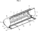
- FIGS. 2 and 3 are diagrams showing a rear surface of the air conditioner 1 according to an exemplary embodiment, wherein FIG. 2 shows the case in which the door 100 is closed and FIG. 3 shows the case in which the door 100 is opened. In FIG. 3 , the lower panel 12 is not shown in order to show a rear surface of the door 100.
- the front panel 10 including the outlet 5 and the side panel 14 may be formed integrally with each other.
- the lower panel 12 may be connected to the side panel 14 and the front panel 10, and the cover 20 and the door 100 may be attached to a front surface of the front panel 10.
- the blade 7 capable of changing a direction in which the air is discharged may be installed on the outlet formed in the front panel 10, and an installation member for installing the blade 7 may be attached to the front surface of the front panel 10.
- An inner portion of the front panel 10 may be provided with driving devices 200 providing power so that the door 100 may be slid.
- the driving devices 200 may be disposed at both sides of an inner surface of the front panel 10 so as to be adjacent to two side panels 14.
- Edges at which all of the side panels 14, the front panel 10, and the lower panel 12 abut together are provided with external openings 30, such that the moving driving devices 200 may be slid together with the door 100 through the external openings 30 to thereby be exposed to the outside. Both sides of the lower panel 12 may be depressed in order to form the external openings 30.
- the driving device 200 may be coupled to one side of the door 100 so as to be slid together with the door 100.
- the driving device 200 may slide the door 100 while moving to the outside of the air conditioner 1 through the external opening 30.
- the installation member for installing the blade 7 and the blade 7 may be exposed.
- Conditioned air may be injected into the interior through the outlet 5 while the blade 7 is rotated.
- the door 100 may include side ribs 102 formed on both sides thereof, wherein the side ribs 120 protrude so as to contact the pair of side panels 14.
- the pair of side panels 14 may include side guides 104 concavely formed along the movement trajectory, respectively, so that the door 100 may be stably moved.
- the side ribs 102 of the door 100 may include protrusions protruding toward the side panels 14 so as to be fitted into the side guides 104 of the side panels 14, respectively.
- the door 100 is slid in the state in which the protrusion is fitted into the side guide 104, thereby making it possible to prevent the door 100 from being separated by external force.
- an inner side of the door 100 may be provided with at least one sag preventing part 170.
- the sag preventing part 107 may have a 'T' shaped cross section and be lengthily extended at an inner side of the door 100 in a direction in which the door 100 is slid.
- a guide 105 may be installed at a lower portion of the outlet so that the sag preventing part 107 may be caught and the door 100 slid.
- the guide 105 may be installed integrally with the installation member for installing the blade 7 or be installed separately from the installation member.
- the guide 105 may be provided with at least one protrusion corresponding to the sag preventing part 107 so that the sag preventing part 107 may be caught.
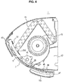
- FIG. 4 is a diagram showing a side of the air conditioner 1 according to an exemplary embodiment.
- An inner portion of the air conditioner 1 is provided with a heat exchanger 16 performing heat exchange with air introduced from the interior to cool or heat the air.
- the heat exchanger 16 serves as an evaporator at the time of a cooling operation and serves as a condenser at the time of a heating operation.
- a plurality of heat exchangers 16 are disposed in the air conditioner 1 so as to effectively perform heat exchange with the air introduced from the interior.
- a cross-flow fan 18 may be positioned together with the heat exchanger 16 in the air conditioner.
- the cross-flow fan 18 may forcibly circulate the air of the interior so that the introduced air is discharged to the interior through the outlet 5.
- the cross-flow fan 18 may have a plurality of wings disposed in a radial direction and be coupled to a driving motor to thereby be rotated at a high speed.
- the inner portion of the air conditioner 1 may be provided with a filter removing dust included in the air sucked from the interior to clean the air and a drain tray draining condensation water generated on a surface of the heat exchanger at the time of the cooling operation to the outside.
- the cross-flow fan 18 When the air conditioner 1 is operated, the cross-flow fan 18 is rotated at a high speed by the driving motor, such that the air of the interior is introduced into the air conditioner through the inlet 3 and is then heat-exchanged while passing through the heat exchanger 16. The air is again discharged to the indoor space through the outlet 5.
- the air conditioner 1 circulates the air by the above-mentioned process to cool or heat the indoor space.
- the driving device 200 moving the door 100 opening and closing the outlet 5 may include a pinion 40 that rotates and a rack 45 engaged and moved with the pinion 40.
- the driving device 200 may include a case 32 forming an appearance so as to protect the pinion 40 and the rack 45 positioned therein.
- the case 32 may be fixed to both sides of the inner surface of the front panel 10.
- the rack 45 may have a form in which a sawtooth is attached to a bar formed in a length direction and bent as a curve. Therefore, the rack 45 may be moved along a curved path depending on rotation of the pinion 40.
- the case 32 may include an internal opening 33 formed at one side thereof so that the rack 45 positioned in the fixed case 32 may be exposed to the outside while moving.
- One side of the rack 45 exposed through the internal opening 33 may be connected to one side of the door 100. That is, one side of the rack 45 and one side of the door 100 may be coupled to each other while having a lower portion of the front panel 10 disposed therebetween.
- the pinion 40 may be rotated and the rack 45 engaged with the pinion 40 may be moved.
- the rack 45 may pass through the internal opening 33 to thereby exit from the case 32, and pass through the external opening 30 provided in the body to thereby be exposed to the outside.
- the door 100 having one side connected to the rack 45 may be moved to a lower portion of the lower panel 12 while being slid together with the rack 45 as the rack 45 is moved.
- One side of the rack 45 and one side of the door 100 are coupled to each other, such that a space in which the lower portion of the front panel 10 may be positioned may be formed between the rack 45 and the door 100. Therefore, the lower portion of the front panel 10 may be formed in a flat plate in which an opening or a coupling member for installing the rack 45 is not present.
- one side of the rack 45 and one side of the door 100 are connected to each other, such that the door 100 and the rack 45 may have different curvatures.
- Both sides of an inner surface of the door 100 may be provided with protrusions 47 protruding inwardly.
- the protrusion 47 may include a rib 49 extended toward the internal opening 33 of the case 32.
- the rack 45 and the rib 49 may be coupled to each other in a length direction of the rack 45, and one side of the rack 45 may be coupled to the protrusion 47 while being fitted into the protrusion 47.
- a screw may be inserted so as to penetrate through the protrusion 47 and one side of the rack 45 that are coupled to each other, thereby fixing the protrusion 47 and one side of the rack 45.
- the rack 45 coupled to the door 100 may include a protrusion protruding downwardly so as to be fitted into the door 100.
- the door 100 may be installed to be slid adjacently to the lower panel 12 in order for the entire volume of the air conditioner 1 to seem to be slim even in the state in which the door 100 is completely opened.
- a curvature of the door 100 may be larger than that of the rack 45.
- the door 100 may have the same curvature as that of the front panel 10 and be attached to the front surface of the front panel 10. As the rack 45 is moved, the door 100 is slid while gradually moving according to the curvature of the rack 45. That is, the door 100 may be slid along a movement trajectory changed from the curvature of the front panel 10 to the curvature of the rack 45.
- FIG. 5 is a diagram showing the driving device 200 of the air conditioner 1 according to an exemplary embodiment.
- the driving device 200 may include a motor 35 providing power, the pinion 40 having a shaft connected to the motor 35 to thereby be rotated, the rack 45 engaged and moved with the pinion 40, and the case 32 enclosing the motor 35, the pinion 40, and the rack 45.
- the rack 45 has one side coupled to the door 100, such that it may be slid together with the door 100.
- the case 32 may include first and second cases 32a and 32b and have an internal space formed therein so that the rack 45, the pinion 40, and the motor 35 may be positioned therein.
- the case 32 may have a form in which it is bent in the length direction in accordance with a form of the rack 45 and have a circular space formed at one side thereof so as to receive the motor 35 and the pinion 40.
- the first and second cases 32a and 32b may be coupled to each other using a hook 34 and be fixed to a rear surface of the front panel 10.
- a torque required in the case in which the door 100 is opened is less than a torque required in the case in which the door ascends against the weight of the door itself to thereby be closed.
- a torque larger than a maximum torque required to open the door 100 is required.
- the driving device 200 When the driving device 200 is provided in accordance with the torque required in the last 20 to 30% section, a gear having a large reduction gear ratio needs to be used or a specification of the motor 35 needs to be high. In the case in which the reduction gear ratio is large, a driving speed is decreased, and in the case in which the motor having the high specification is used, efficiency is decreased in terms of a size and a cost. Therefore, it is efficient to satisfy the torque required in the last 20 to 30% section by finding a method of securing a torque margin.
- the motor 35 may be a step motor rotated by a predetermined angle depending on input pulses.
- the step motor may be controlled by a pulse per second (PPS).
- PPS pulse per second
- the PSS is slightly slowly controlled, thereby making it possible to control a torque.
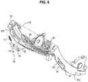
- FIG. 6 is a diagram showing the driving device 200 of the air conditioner 1 according to an exemplary embodiment.
- auxiliary device 70 providing elastic force.
- the auxiliary device 70 may be positioned together with the rack 45 and the pinion 40 in the case 32.
- the auxiliary device 70 may include a spring 72 providing the elastic force and a connection member 74 having one side connected to the spring 72 to thereby be moved.
- the auxiliary device 70 may be installed in the vicinity of the last 20 to 30% of an ascending section so as to provide the elastic force to the rack 45.
- the spring 72 may be fixed to a connector 39 positioned at one side of the case 32, and the connection member 74 may be connected to a side of the spring 72 opposite to one side of the spring 72 fixed to the connector 39.
- a side of the connection member 74 opposite to the side of the connection member 74 connected to the spring 72 may be coupled to the rack 45 so that the connection member 74 may be moved while expanding and contracting the spring 72 as the rack 45 is moved.
- connection member 74 may have a similar plate shape, and one side thereof may be similar length to that of the rack 45.
- the connection member 74 may have a concave surface 78 formed at a central portion thereof so that the rack 45 may be coupled thereto, and a lower portion of the rack 45 may be convexly formed so as to correspond to the concave surface 78,
- One side of the rack 45 may be put on the connection member 74, and the lower portion of the rack 45 may be coupled to the concave surface 78.
- a section in which the rack 45 and the connection member 74 are coupled to each other and are moved is called an interworking section.
- Both sides of the concave surface 78 may be provided with a plurality of protrusions 76 and 77 protruding outwardly.
- the protrusions 76 and 77 are formed so as to correspond to both sides of the connection member 74, such that a total of four protrusions, that is, a pair of upper protrusions 77 and a pair of lower protrusions 76 may be formed.
- the pair of upper protrusions 77 and the pair of lower protrusions 76 may be fitted into auxiliary guides 36 formed along a movement path of the connection member 74 at both sides of the case 34.
- connection member 74 may also be moved downwardly along the rack 45 fixed to the concave surface 78.
- the upper and lower protrusions 77 and 76 are moved while being slid along the auxiliary guides 36, and the spring 72 connected to the connection member 74 is expanded.
- One side of the auxiliary guide 36 may be provided with a bent fixing groove 37 so that the connection member 74 is separated from the rack 45 and is fixed in the state in which the spring 72 is expanded.
- connection member 74 is inclined while the lower protrusion 76 of the connection member 74 moved along the rack 45 is fitted into the bent fixing groove 37.
- the rack 45 may be separated from the concave surface 78 of the inclined connection member 74 and move the door 100 while being continuously moved downwardly.
- the connection member 74 may be fixed in the state in which the lower protrusion 76 is fitted into the fixing groove 37, and the spring 72 may be fixed in the state in which it is expanded by a movement distance of the connection member 74.
- the rack 45 may ascend while being again moved inwardly of the case 32 and be again coupled to the connection member 74 fixed to the vicinity of a start point of the interworking section.
- the connection member 74 that has been inclined may again return to the state in which it is not inclined while being coupled to the rack 45, and the lower protrusion 76 may exit from the fixing groove 37.
- the spring 72 starts to compress the connection member 74 with elastic force with which it is to return to its original state, thereby making it possible to provide force to the rack 45 through the connection member 74 connected thereto to allow the rack 45 to ascend. Therefore, in the interworking section, force of the motor 35 and the elastic force of the spring 72 are summed, such that the rack 45 ascends to the end. As a result, the door 100 may be again attached to the front surface of the front panel 10.
- FIG. 7 is a diagram showing a diagram showing the case 32 of the driving device 200 of the air conditioner 1 according to an exemplary embodiment.
- the second case 32b of the driving device 200 has been shown in FIG. 7 , and the first and second cases 32a and 32b have the same configuration as each other.
- the second case 32b may be coupled to the first case 32a using the hook 34 to form a space in which the auxiliary device 70, the rack 45, the pinion 40, and the like, may be positioned.
- One side of the second case 32b may be provided with the internal opening 33 so that the rack 45 may be moved outwardly, and the other side thereof may be provided with the connector 39 to which the spring 72 may be fixed.
- the auxiliary guide 36 and the fixing groove 37 may be disposed in the interworking section in which the connection member 74 of the second case 32b is moved together with the rack 45.
- the auxiliary guide 36 may be provided with a safety groove 80 into which the protrusions 76 and 77 may be inserted, in addition to the fixing groove 37.
- the lower protrusion 76 of the connection member 74 is fitted into and fixed to the fixing groove 37.
- the lower protrusion 76 deviates from the fixing groove 37 due to external impact, such that the connection member 74 may be moved upwardly by the elastic force of the spring 72.
- the safety groove 80 is provided, such that the lower protrusion 76 is inserted into the safety groove 80 and then returns to the fixing groove 37, thereby making it possible to couple the rack 45 to the concave surface 78.
- An inner surface of the case 32b may be provided with a guide 38 concavely formed along a movement path of the rack 45 so that the rack 45 may be stably moved.
- the guide 38 may be extended from one side of the case 32b to the other side of the case 32b along the movement path of the rack 45.
- contact friction between the rack 45 and the guide 38 may be increased.
- the guide 38 may be formed in a minimum section in which the rack 45 may be stably moved along the movement path.
- FIG. 8A is a diagram showing a driving device and FIG. 8B is a diagram showing a cross section of the driving device 200 of the air conditioner 1 according to an exemplary embodiment.
- the rack 45 may have an upper surface on which a sawtooth engaged with the pinion 40 is formed and both sides on which rack ribs 46 movable along the guide 38 are formed.
- the rack rib 46 may be fitted into a contact surface 48 positioned on an inner surface of the guide 38 and be slid.
- the contact surface 48 may have a form in which it encloses upper and lower portions of the rack rib 46 so that the rack rib 46 does not deviate from the guide 38. Due to the contact surface 48 contacting the rack rib 46 in the form in which it encloses the upper and lower portions of the rack rib 46, the contact friction may be increased. Therefore, in order to decrease the contact friction between the rack rib 46 and the contact surface 48, the rack rib 46 may be inserted into the contact surface 48 while having a gap.
- the rack rib 46 has a gradient larger than that of the contact surface 48, such that the rack rib 46 and the contact surface 48 do not surface-contact each other, but may line-contact each other. An empty space is formed between the rack rib 46 and the contact surface 48 contacting each other, such that the contact friction may be decreased.
- a clean and smooth appearance may be formed using a door slid along a curved path and a slim appearance may be formed even in the state in which the door is opened.
- a time required for driving the door may be decreased using a spring.
Landscapes
- Engineering & Computer Science (AREA)
- Chemical & Material Sciences (AREA)
- Combustion & Propulsion (AREA)
- Mechanical Engineering (AREA)
- General Engineering & Computer Science (AREA)
- Physics & Mathematics (AREA)
- Thermal Sciences (AREA)
- Air Filters, Heat-Exchange Apparatuses, And Housings Of Air-Conditioning Units (AREA)
- Air-Flow Control Members (AREA)
Claims (15)
- Klimaanlage (1) zur Installation auf einer Wand, wobei die Klimaanlage Folgendes umfasst:ein vorderes Paneel (10), das ein erstes Paneelteil, das einen Einlass (3) aufweist, und ein zweites Paneelteil, das mit einem unteren Abschnitt des ersten Paneelteils verbunden ist und einen Auslass (5) aufweist, beinhaltet;
undein unteres Paneel (12), das mit dem zweiten Paneelteil des vorderen Paneels (10) verbunden ist und sich zu der Wand hin erstreckt;eine Tür (100), die auf einer vorderen Oberfläche des zweiten Paneelteils installiert ist, um den Auslass (5) zu öffnen und zu schließen,dadurch gekennzeichnet, dass die Tür (100) entlang einer gekrümmten Bewegungsbahn von einer ersten Position, in der der Auslass (5) verdeckt ist, zu einer zweiten Position, in der die Tür (100) an dem unteren Paneel (12) angrenzt und der Auslass (5) exponiert ist, zu dem unteren Paneel (12) hin verschiebbar ist und eine Krümmung der gekrümmten Bewegungsbahn eingerichtet ist, um geändert zu werden,wobei die Tür eine Zahnstange beinhaltet, die von der Tür beabstandet und in einer Position relativ zu dieser fixiert ist, im Wesentlichen parallel zu einer hinteren Oberfläche der Tür, von der Tür abgewandt, und von einem Ritzel in Eingriff genommen und bewegt wird, um dadurch die Tür zu bewegen, undwobei die Zahnstange mit der Tür an einem ersten Ende der Zahnstange verbunden ist, sodass sich ein Innenraum zwischen der Zahnstange und der Tür kontinuierlich von dem ersten Ende der Zahnstange zu einem zweiten Ende der Zahnstange gegenüber dem ersten Ende der Zahnstange und zu einem Außenraum der Tür und der Zahnstange erstreckt. - Klimaanlage (1) gemäß Anspruch 1, die ferner eine Antriebsvorrichtung (200) umfasst, die an einer Seite eines inneren Abschnitts des zweiten Paneelteils positioniert ist und Leistung bereitstellt, sodass die Tür (100) verschiebbar ist.
- Klimaanlage (1) gemäß Anspruch 2, wobei die Antriebsvorrichtung (200) einen Motor (35) beinhaltet, der die Leistung bereitstellt, das Ritzel (40) eine Welle aufweist, die mit dem Motor (35) verbunden ist, um dadurch gedreht zu werden, und die Zahnstange (45) mit dem Ritzel (40) in Eingriff genommen und bewegt wird.
- Klimaanlage (1) gemäß Anspruch 3, wobei eine Seite der Zahnstange (45) und eine Seite der Tür (100) miteinander gekoppelt sind, während das zweite Paneelteil dazwischen angeordnet ist, sodass die Tür (100) bewegbar ist, wenn sich die Zahnstange (45) zu dem unteren Paneel (12) hin bewegt.
- Klimaanlage (1) gemäß Anspruch 4, wobei:sich die Zahnstange (45) in einer Längsrichtung erstreckt, während sie eine Krümmung aufweist, unddie Tür (100) und die Zahnstange (45) unterschiedliche Krümmungen aufweisen.
- Klimaanlage (1) gemäß Anspruch 5, wobei eine Krümmung der Tür (100) größer als die Krümmung der Zahnstange (45) ist, sodass die Tür (100) angrenzend an das untere Paneel (12) verschiebbar ist.
- Klimaanlage (1) gemäß einem der vorhergehenden Ansprüche, wobei:
der erste und zweite Paneelteil als gekrümmte Oberfläche ausgebildet sind, sodass das vordere Paneel (10) herausragt, um in Bezug auf die Wand konvex zu sein. - Klimaanlage (1) gemäß Anspruch 7, wobei:eine Seite des ersten Paneelteils eingerichtet ist, um die Wand zu berühren, undeine Seite des zweiten Paneelteils von der Wand beabstandet ist, sodass das untere Paneel (12) positioniert ist.
- Klimaanlage (1) gemäß Anspruch 8, die ferner eine Abdeckung (20) umfasst, die obere Abschnitte des ersten und zweiten Paneelteils abdeckt,
wobei die Tür (100) mit der Abdeckung verbunden ist, um einen unteren Abschnitt des zweiten Paneelteils abzudecken, und
wobei die Abdeckung (20) und die Tür (100) die gleiche Dicke aufweisen, um eine glatte Oberfläche auszubilden. - Klimaanlage (1) gemäß einem der vorhergehenden Ansprüche, die ferner ein Paar Seitenpaneele (14) aufweist, die auf beiden Seiten des vorderen Paneels (10) und des unteren Paneels (12) installiert sind,
wobei die Tür (100) Seitenrippen (102) auf beiden Seiten davon beinhaltet, wobei die Seitenrippen (102) herausragen, um das Paar Seitenpaneele (14) zu berühren. - Klimaanlage (1) gemäß Anspruch 10, wobei:das Paar Seitenpaneele (14) Seitenführungen (104) beinhaltet, die jeweils auf äußeren Oberflächen davon entlang der gekrümmten Bewegungsbahn konkav ausgebildet sind, sodass die Tür (100) stabil bewegbar ist, unddie Seitenrippen (102) Vorsprünge beinhalten, die zu dem Paar Seitenpaneele (14) hin herausragen, um jeweils in die Seitenführungen eingepasst zu werden.
- Klimaanlage (1) gemäß einem der vorhergehenden Ansprüche, wenn von Anspruch 3 abhängig, wobei der Motor (35) ein Schrittmotor ist, der um einen vorher festgelegten Winkel abhängig von Eingangsimpulsen gedreht wird.
- Klimaanlage (1) gemäß einem der vorhergehenden Ansprüche, wenn von Anspruch 3 abhängig, die ferner eine Hilfsvorrichtung (70) umfasst, die installiert ist, um die Tür (100) elastisch nach oben vorzuspannen,
wobei die Hilfsvorrichtung (70) eine Feder (72), die eine elastische Kraft bereitstellt, und ein Verbindungsglied (74), das mit einer Seite der Feder (72) verbunden ist, um dadurch bewegt zu werden, beinhaltet. - Klimaanlage (1) gemäß Anspruch 13, wobei eine Seite der Feder (72) fixiert ist und eine Seite des Verbindungsglieds (74) gegenüber der Seite des Verbindungsglieds (74), die mit der Feder (72) verbunden ist, mit der Zahnstange (45) gekoppelt ist, sodass das Verbindungsglied (74) bewegbar ist, wenn die Zahnstange (45) bewegt wird.
- Klimaanlage (1) gemäß Anspruch 14, wobei:in einem Fall, in dem die Zahnstange (45) zu dem unteren Paneel (12) hin bewegt wird, das Verbindungsglied (74) von der Zahnstange (45) getrennt wird und in dem Zustand fixiert wird, in dem die Feder (72) expandiert ist; undin einem Fall, in dem sich die Zahnstange (45) wieder nach oben bewegt, das Verbindungsglied (74) mit der Zahnstange (45) gekoppelt wird, wodurch eine elastische Kraft der Feder (72) aufgenommen wird.
Applications Claiming Priority (1)
| Application Number | Priority Date | Filing Date | Title |
|---|---|---|---|
| KR1020130111528A KR102152645B1 (ko) | 2013-09-17 | 2013-09-17 | 공기조화기 |
Publications (2)
| Publication Number | Publication Date |
|---|---|
| EP2848872A1 EP2848872A1 (de) | 2015-03-18 |
| EP2848872B1 true EP2848872B1 (de) | 2020-03-18 |
Family
ID=51535387
Family Applications (1)
| Application Number | Title | Priority Date | Filing Date |
|---|---|---|---|
| EP14184830.9A Active EP2848872B1 (de) | 2013-09-17 | 2014-09-15 | Klimaanlage |
Country Status (5)
| Country | Link |
|---|---|
| US (1) | US10393422B2 (de) |
| EP (1) | EP2848872B1 (de) |
| KR (1) | KR102152645B1 (de) |
| CN (1) | CN104456899B (de) |
| ES (1) | ES2797545T3 (de) |
Families Citing this family (32)
| Publication number | Priority date | Publication date | Assignee | Title |
|---|---|---|---|---|
| US11060754B2 (en) | 2015-06-05 | 2021-07-13 | Novinium, Inc. | Ventilation system for manhole vault |
| US10962253B2 (en) | 2015-06-05 | 2021-03-30 | Novinium, Inc. | Systems for circulating air inside a manhole vault |
| CN106338105B (zh) * | 2015-07-08 | 2020-04-10 | 松下知识产权经营株式会社 | 吸气装置以及吸气方法 |
| WO2017014478A1 (ko) * | 2015-07-17 | 2017-01-26 | 삼성전자주식회사 | 공기조화기 |
| KR102513480B1 (ko) | 2015-07-17 | 2023-03-27 | 삼성전자주식회사 | 공기조화기 |
| US10684031B2 (en) * | 2016-03-31 | 2020-06-16 | Novinium, Inc. | Smart system for manhole event suppression system |
| CN106016680B (zh) * | 2016-07-18 | 2021-08-24 | 珠海格力电器股份有限公司 | 一种空调及室外机的出风口防尘机构 |
| KR102600956B1 (ko) * | 2016-09-22 | 2023-11-13 | 삼성전자주식회사 | 공기조화기 |
| CN106287990A (zh) * | 2016-09-30 | 2017-01-04 | 美的集团武汉制冷设备有限公司 | 空调挂机 |
| KR102629978B1 (ko) * | 2016-10-21 | 2024-01-29 | 삼성전자주식회사 | 공기조화기 |
| KR101890869B1 (ko) | 2016-10-27 | 2018-08-22 | 삼성전자주식회사 | 공기조화기 |
| KR102420499B1 (ko) * | 2016-10-27 | 2022-07-13 | 삼성전자주식회사 | 공기조화기 |
| CN106288276A (zh) * | 2016-11-21 | 2017-01-04 | 珠海格力电器股份有限公司 | 一种空调及其出风口开闭机构 |
| CH713390A1 (de) * | 2017-01-27 | 2018-07-31 | Belimo Holding Ag | Linearantrieb und Verfahren zum Montieren eines solchen Linearantriebes. |
| CN106885357A (zh) * | 2017-03-13 | 2017-06-23 | 奥克斯空调股份有限公司 | 一种空调器出风窗组件 |
| CN106949615B (zh) * | 2017-03-17 | 2019-06-07 | 珠海格力电器股份有限公司 | 出风结构、空调器的出风方法和空调器 |
| KR102391356B1 (ko) * | 2017-04-28 | 2022-04-28 | 삼성전자주식회사 | 공기조화기 |
| CN107143924B (zh) * | 2017-07-05 | 2019-08-27 | 珠海格力电器股份有限公司 | 室内机壳体结构及具有其的空调室内机 |
| CN108592374B (zh) * | 2018-05-24 | 2023-07-14 | 珠海格力电器股份有限公司 | 支撑结构及具有其的空调器 |
| CN109520104B (zh) * | 2018-11-08 | 2024-01-23 | 珠海格力电器股份有限公司 | 一种空调器室内机导风结构及空调器 |
| CN112344533B (zh) * | 2019-08-07 | 2025-10-28 | 广东美的制冷设备有限公司 | 空调的滑门控制方法、空调的滑门控制系统、空调和计算机可读存储介质 |
| CN112344531B (zh) * | 2019-08-07 | 2022-02-25 | 广东美的制冷设备有限公司 | 空调的网罩清洗控制方法、系统及空调 |
| CN111006314B (zh) * | 2019-12-05 | 2021-12-21 | 青岛海尔空调器有限总公司 | 空调内机 |
| CN111140918B (zh) * | 2020-01-17 | 2023-06-30 | 珠海格力电器股份有限公司 | 一种上下出风空调室内机、控制方法和空调器 |
| CN111351202B (zh) * | 2020-04-13 | 2025-04-18 | 宁波奥克斯电气有限公司 | 一种驱动机构及空调器 |
| CN113719996B (zh) * | 2020-05-25 | 2025-04-18 | 宁波奥克斯电气有限公司 | 分离式齿条结构和空调器 |
| CN113719997B (zh) * | 2020-05-25 | 2025-04-18 | 宁波奥克斯电气有限公司 | 可拆装运动机构、可拆装滑动门和空调器 |
| CN113719893B (zh) * | 2020-05-25 | 2025-04-18 | 宁波奥克斯电气有限公司 | 空调器 |
| KR102480008B1 (ko) * | 2020-08-20 | 2022-12-20 | 엘지전자 주식회사 | 공기청정기 |
| WO2022090777A1 (en) * | 2020-10-30 | 2022-05-05 | Daikin Industries (Thailand) Ltd. | An indoor unit for an air conditioner |
| EP4242533A4 (de) * | 2020-12-11 | 2024-04-17 | GD Midea Air-Conditioning Equipment Co., Ltd. | Antriebsmechanismus und klimaanlage |
| CN114629063B (zh) * | 2020-12-11 | 2025-07-25 | 广东美的制冷设备有限公司 | 驱动机构及空调器 |
Citations (1)
| Publication number | Priority date | Publication date | Assignee | Title |
|---|---|---|---|---|
| US20170176026A1 (en) * | 2014-02-11 | 2017-06-22 | Samsung Electronics Co., Ltd | Air conditioner |
Family Cites Families (28)
| Publication number | Priority date | Publication date | Assignee | Title |
|---|---|---|---|---|
| US2031320A (en) * | 1931-06-01 | 1936-02-18 | Hotchkiss Co E H | Staple driving machine |
| CN1086462A (zh) | 1993-06-16 | 1994-05-11 | 向学雷 | 辊盘式破碎机 |
| KR100215048B1 (ko) * | 1996-03-21 | 1999-08-16 | 윤종용 | 공기조화기의 토출구 개폐장치 |
| US6609563B1 (en) * | 1999-04-13 | 2003-08-26 | Calsonic Kansei Corporation | Vehicular air conditioning apparatus including a detachably installed mix door assembly |
| JP4006174B2 (ja) * | 2000-09-20 | 2007-11-14 | 株式会社大井製作所 | 車両における開閉体の開閉装置 |
| US20040111970A1 (en) * | 2002-04-18 | 2004-06-17 | Fenelon Paul J. | Window lift mechanism |
| KR100453240B1 (ko) * | 2002-09-30 | 2004-10-15 | 삼성전자주식회사 | 공기조화기의 실내기 |
| EP1634736B1 (de) * | 2003-06-09 | 2009-07-29 | Valeo Thermal Systems Japan Corporation | Schiebetürvorrichtung für klimaanlage |
| TWI259890B (en) * | 2003-09-16 | 2006-08-11 | Lg Electronics Inc | Integral type air conditioner |
| WO2006006623A1 (ja) * | 2004-07-14 | 2006-01-19 | Daikin Industries, Ltd. | 空気調和機の室内機 |
| AU2005260871B8 (en) * | 2004-07-14 | 2008-11-06 | Daikin Industries, Ltd. | Indoor unit of an air conditioner |
| DE602004022467D1 (de) * | 2004-08-16 | 2009-09-17 | Lg Electronics Inc | Filtereinheit einer klimaanlage |
| CN1888591A (zh) | 2005-06-28 | 2007-01-03 | 乐金电子(天津)电器有限公司 | 室内机前面板开闭结构 |
| ES2324365T3 (es) * | 2005-10-11 | 2009-08-05 | Fujitsu General Limited | Aparato de aire acondicionado. |
| KR100776595B1 (ko) * | 2006-09-04 | 2007-11-15 | 삼성전자주식회사 | 공기조화기 |
| ES2392366T3 (es) * | 2007-08-28 | 2012-12-10 | Mitsubishi Electric Corporation | Acondicionador de aire |
| JP4430697B2 (ja) | 2007-08-28 | 2010-03-10 | 三菱電機株式会社 | 空気調和機 |
| US8935883B2 (en) * | 2008-07-29 | 2015-01-20 | The Chamberlain Group, Inc. | Barrier operator with rack and pinion drive and coupling assembly for an integrated door and operator |
| KR101503930B1 (ko) | 2008-11-10 | 2015-03-24 | 엘지전자 주식회사 | 공기 조화기의 실내기 |
| JP2010286194A (ja) | 2009-06-12 | 2010-12-24 | Daikin Ind Ltd | 空気調和機の室内機 |
| JP4645755B2 (ja) * | 2009-07-13 | 2011-03-09 | ダイキン工業株式会社 | 空気調和機の室内機 |
| US20110059685A1 (en) * | 2009-09-08 | 2011-03-10 | Keihin Corporation | Slide damper device |
| JP5470084B2 (ja) * | 2010-02-17 | 2014-04-16 | 株式会社ケーヒン | スライドドア装置 |
| KR101781845B1 (ko) * | 2010-05-13 | 2017-09-26 | 엘지전자 주식회사 | 공기조화장치의 실내기 |
| JP5568408B2 (ja) * | 2010-08-23 | 2014-08-06 | 株式会社ケーヒン | 車両用空気調和装置 |
| CN202470348U (zh) * | 2012-02-29 | 2012-10-03 | 珠海格力电器股份有限公司 | 导风板驱动装置及使用该驱动装置的空调室内机 |
| KR102055939B1 (ko) * | 2012-10-10 | 2019-12-13 | 엘지전자 주식회사 | 공기 조화기 |
| CN105423522B (zh) * | 2015-12-21 | 2017-11-17 | 珠海格力电器股份有限公司 | 一种导风板推出机构及空调器 |
-
2013
- 2013-09-17 KR KR1020130111528A patent/KR102152645B1/ko active Active
-
2014
- 2014-08-25 US US14/467,551 patent/US10393422B2/en not_active Expired - Fee Related
- 2014-09-15 EP EP14184830.9A patent/EP2848872B1/de active Active
- 2014-09-15 ES ES14184830T patent/ES2797545T3/es active Active
- 2014-09-17 CN CN201410475196.XA patent/CN104456899B/zh not_active Expired - Fee Related
Patent Citations (1)
| Publication number | Priority date | Publication date | Assignee | Title |
|---|---|---|---|---|
| US20170176026A1 (en) * | 2014-02-11 | 2017-06-22 | Samsung Electronics Co., Ltd | Air conditioner |
Also Published As
| Publication number | Publication date |
|---|---|
| CN104456899A (zh) | 2015-03-25 |
| KR102152645B1 (ko) | 2020-09-08 |
| US10393422B2 (en) | 2019-08-27 |
| EP2848872A1 (de) | 2015-03-18 |
| US20150075201A1 (en) | 2015-03-19 |
| CN104456899B (zh) | 2019-06-25 |
| KR20150031832A (ko) | 2015-03-25 |
| ES2797545T3 (es) | 2020-12-02 |
Similar Documents
| Publication | Publication Date | Title |
|---|---|---|
| EP2848872B1 (de) | Klimaanlage | |
| KR102217011B1 (ko) | 공기조화기 | |
| EP3892932B1 (de) | Klimaanlage | |
| EP2719969B1 (de) | Klimaanlage | |
| EP2821716B1 (de) | Inneneinheit einer Klimaanlage mit Windabweiser für den Luftauslass | |
| KR100755139B1 (ko) | 공기 조화기 | |
| EP2719959B1 (de) | Klimaanlage | |
| KR101781845B1 (ko) | 공기조화장치의 실내기 | |
| EP3070410B1 (de) | Ausseneinheit einer klimaanlage | |
| KR102500804B1 (ko) | 공기 조화기의 루버 장치 | |
| WO2002103249A2 (en) | Air conditioner | |
| EP4086532B1 (de) | Klimaanlageninnenraumeinheit | |
| EP2312246A2 (de) | Eingebautes elektrisches Haushaltsgerät | |
| KR100644544B1 (ko) | 공기조화기 | |
| KR100642364B1 (ko) | 분리형 공기조화기의 실내기 | |
| KR102457778B1 (ko) | 공기조화기 | |
| CN221463905U (zh) | 空调器 | |
| KR101086612B1 (ko) | 공기 조화기 실내기의 토출구 개폐구조 | |
| KR102521853B1 (ko) | 공기조화기 | |
| WO2006080599A2 (en) | Heat exchange unit with vent | |
| EP1804002A1 (de) | In der decke eingebettete klimaanlage | |
| KR20090082729A (ko) | 천장형 공기조화기 | |
| KR20190117068A (ko) | 팬어셈블리 및 공기조화기 | |
| KR20050089200A (ko) | 공기 조화기 실내기의 토출구 개폐구조 | |
| KR20250046465A (ko) | 공기조화기 |
Legal Events
| Date | Code | Title | Description |
|---|---|---|---|
| PUAI | Public reference made under article 153(3) epc to a published international application that has entered the european phase |
Free format text: ORIGINAL CODE: 0009012 |
|
| 17P | Request for examination filed |
Effective date: 20140915 |
|
| AK | Designated contracting states |
Kind code of ref document: A1 Designated state(s): AL AT BE BG CH CY CZ DE DK EE ES FI FR GB GR HR HU IE IS IT LI LT LU LV MC MK MT NL NO PL PT RO RS SE SI SK SM TR |
|
| AX | Request for extension of the european patent |
Extension state: BA ME |
|
| R17P | Request for examination filed (corrected) |
Effective date: 20150918 |
|
| RBV | Designated contracting states (corrected) |
Designated state(s): AL AT BE BG CH CY CZ DE DK EE ES FI FR GB GR HR HU IE IS IT LI LT LU LV MC MK MT NL NO PL PT RO RS SE SI SK SM TR |
|
| STAA | Information on the status of an ep patent application or granted ep patent |
Free format text: STATUS: EXAMINATION IS IN PROGRESS |
|
| 17Q | First examination report despatched |
Effective date: 20170720 |
|
| REG | Reference to a national code |
Ref country code: DE Ref legal event code: R079 Ref document number: 602014062438 Country of ref document: DE Free format text: PREVIOUS MAIN CLASS: F24F0001000000 Ipc: F24F0001001100 |
|
| RIC1 | Information provided on ipc code assigned before grant |
Ipc: F24F 1/00 20190101ALI20190724BHEP Ipc: F24F 1/0011 20190101AFI20190724BHEP Ipc: F24F 13/14 20060101ALI20190724BHEP |
|
| GRAP | Despatch of communication of intention to grant a patent |
Free format text: ORIGINAL CODE: EPIDOSNIGR1 |
|
| STAA | Information on the status of an ep patent application or granted ep patent |
Free format text: STATUS: GRANT OF PATENT IS INTENDED |
|
| INTG | Intention to grant announced |
Effective date: 20191001 |
|
| GRAS | Grant fee paid |
Free format text: ORIGINAL CODE: EPIDOSNIGR3 |
|
| GRAA | (expected) grant |
Free format text: ORIGINAL CODE: 0009210 |
|
| STAA | Information on the status of an ep patent application or granted ep patent |
Free format text: STATUS: THE PATENT HAS BEEN GRANTED |
|
| RAP1 | Party data changed (applicant data changed or rights of an application transferred) |
Owner name: SAMSUNG ELECTRONICS CO., LTD. |
|
| AK | Designated contracting states |
Kind code of ref document: B1 Designated state(s): AL AT BE BG CH CY CZ DE DK EE ES FI FR GB GR HR HU IE IS IT LI LT LU LV MC MK MT NL NO PL PT RO RS SE SI SK SM TR |
|
| REG | Reference to a national code |
Ref country code: GB Ref legal event code: FG4D |
|
| REG | Reference to a national code |
Ref country code: DE Ref legal event code: R096 Ref document number: 602014062438 Country of ref document: DE |
|
| REG | Reference to a national code |
Ref country code: AT Ref legal event code: REF Ref document number: 1246337 Country of ref document: AT Kind code of ref document: T Effective date: 20200415 Ref country code: IE Ref legal event code: FG4D |
|
| PG25 | Lapsed in a contracting state [announced via postgrant information from national office to epo] |
Ref country code: FI Free format text: LAPSE BECAUSE OF FAILURE TO SUBMIT A TRANSLATION OF THE DESCRIPTION OR TO PAY THE FEE WITHIN THE PRESCRIBED TIME-LIMIT Effective date: 20200318 Ref country code: NO Free format text: LAPSE BECAUSE OF FAILURE TO SUBMIT A TRANSLATION OF THE DESCRIPTION OR TO PAY THE FEE WITHIN THE PRESCRIBED TIME-LIMIT Effective date: 20200618 Ref country code: RS Free format text: LAPSE BECAUSE OF FAILURE TO SUBMIT A TRANSLATION OF THE DESCRIPTION OR TO PAY THE FEE WITHIN THE PRESCRIBED TIME-LIMIT Effective date: 20200318 |
|
| REG | Reference to a national code |
Ref country code: NL Ref legal event code: MP Effective date: 20200318 |
|
| PG25 | Lapsed in a contracting state [announced via postgrant information from national office to epo] |
Ref country code: BG Free format text: LAPSE BECAUSE OF FAILURE TO SUBMIT A TRANSLATION OF THE DESCRIPTION OR TO PAY THE FEE WITHIN THE PRESCRIBED TIME-LIMIT Effective date: 20200618 Ref country code: HR Free format text: LAPSE BECAUSE OF FAILURE TO SUBMIT A TRANSLATION OF THE DESCRIPTION OR TO PAY THE FEE WITHIN THE PRESCRIBED TIME-LIMIT Effective date: 20200318 Ref country code: SE Free format text: LAPSE BECAUSE OF FAILURE TO SUBMIT A TRANSLATION OF THE DESCRIPTION OR TO PAY THE FEE WITHIN THE PRESCRIBED TIME-LIMIT Effective date: 20200318 Ref country code: LV Free format text: LAPSE BECAUSE OF FAILURE TO SUBMIT A TRANSLATION OF THE DESCRIPTION OR TO PAY THE FEE WITHIN THE PRESCRIBED TIME-LIMIT Effective date: 20200318 Ref country code: GR Free format text: LAPSE BECAUSE OF FAILURE TO SUBMIT A TRANSLATION OF THE DESCRIPTION OR TO PAY THE FEE WITHIN THE PRESCRIBED TIME-LIMIT Effective date: 20200619 |
|
| REG | Reference to a national code |
Ref country code: LT Ref legal event code: MG4D |
|
| PG25 | Lapsed in a contracting state [announced via postgrant information from national office to epo] |
Ref country code: NL Free format text: LAPSE BECAUSE OF FAILURE TO SUBMIT A TRANSLATION OF THE DESCRIPTION OR TO PAY THE FEE WITHIN THE PRESCRIBED TIME-LIMIT Effective date: 20200318 |
|
| PG25 | Lapsed in a contracting state [announced via postgrant information from national office to epo] |
Ref country code: CZ Free format text: LAPSE BECAUSE OF FAILURE TO SUBMIT A TRANSLATION OF THE DESCRIPTION OR TO PAY THE FEE WITHIN THE PRESCRIBED TIME-LIMIT Effective date: 20200318 Ref country code: LT Free format text: LAPSE BECAUSE OF FAILURE TO SUBMIT A TRANSLATION OF THE DESCRIPTION OR TO PAY THE FEE WITHIN THE PRESCRIBED TIME-LIMIT Effective date: 20200318 Ref country code: SM Free format text: LAPSE BECAUSE OF FAILURE TO SUBMIT A TRANSLATION OF THE DESCRIPTION OR TO PAY THE FEE WITHIN THE PRESCRIBED TIME-LIMIT Effective date: 20200318 Ref country code: SK Free format text: LAPSE BECAUSE OF FAILURE TO SUBMIT A TRANSLATION OF THE DESCRIPTION OR TO PAY THE FEE WITHIN THE PRESCRIBED TIME-LIMIT Effective date: 20200318 Ref country code: RO Free format text: LAPSE BECAUSE OF FAILURE TO SUBMIT A TRANSLATION OF THE DESCRIPTION OR TO PAY THE FEE WITHIN THE PRESCRIBED TIME-LIMIT Effective date: 20200318 Ref country code: IS Free format text: LAPSE BECAUSE OF FAILURE TO SUBMIT A TRANSLATION OF THE DESCRIPTION OR TO PAY THE FEE WITHIN THE PRESCRIBED TIME-LIMIT Effective date: 20200718 Ref country code: PT Free format text: LAPSE BECAUSE OF FAILURE TO SUBMIT A TRANSLATION OF THE DESCRIPTION OR TO PAY THE FEE WITHIN THE PRESCRIBED TIME-LIMIT Effective date: 20200812 Ref country code: EE Free format text: LAPSE BECAUSE OF FAILURE TO SUBMIT A TRANSLATION OF THE DESCRIPTION OR TO PAY THE FEE WITHIN THE PRESCRIBED TIME-LIMIT Effective date: 20200318 |
|
| REG | Reference to a national code |
Ref country code: AT Ref legal event code: MK05 Ref document number: 1246337 Country of ref document: AT Kind code of ref document: T Effective date: 20200318 |
|
| PGFP | Annual fee paid to national office [announced via postgrant information from national office to epo] |
Ref country code: IT Payment date: 20200914 Year of fee payment: 7 |
|
| REG | Reference to a national code |
Ref country code: ES Ref legal event code: FG2A Ref document number: 2797545 Country of ref document: ES Kind code of ref document: T3 Effective date: 20201202 |
|
| REG | Reference to a national code |
Ref country code: DE Ref legal event code: R097 Ref document number: 602014062438 Country of ref document: DE |
|
| PLBE | No opposition filed within time limit |
Free format text: ORIGINAL CODE: 0009261 |
|
| STAA | Information on the status of an ep patent application or granted ep patent |
Free format text: STATUS: NO OPPOSITION FILED WITHIN TIME LIMIT |
|
| PG25 | Lapsed in a contracting state [announced via postgrant information from national office to epo] |
Ref country code: AT Free format text: LAPSE BECAUSE OF FAILURE TO SUBMIT A TRANSLATION OF THE DESCRIPTION OR TO PAY THE FEE WITHIN THE PRESCRIBED TIME-LIMIT Effective date: 20200318 Ref country code: DK Free format text: LAPSE BECAUSE OF FAILURE TO SUBMIT A TRANSLATION OF THE DESCRIPTION OR TO PAY THE FEE WITHIN THE PRESCRIBED TIME-LIMIT Effective date: 20200318 |
|
| PGFP | Annual fee paid to national office [announced via postgrant information from national office to epo] |
Ref country code: ES Payment date: 20201001 Year of fee payment: 7 |
|
| 26N | No opposition filed |
Effective date: 20201221 |
|
| PG25 | Lapsed in a contracting state [announced via postgrant information from national office to epo] |
Ref country code: PL Free format text: LAPSE BECAUSE OF FAILURE TO SUBMIT A TRANSLATION OF THE DESCRIPTION OR TO PAY THE FEE WITHIN THE PRESCRIBED TIME-LIMIT Effective date: 20200318 |
|
| REG | Reference to a national code |
Ref country code: DE Ref legal event code: R119 Ref document number: 602014062438 Country of ref document: DE |
|
| PG25 | Lapsed in a contracting state [announced via postgrant information from national office to epo] |
Ref country code: MC Free format text: LAPSE BECAUSE OF FAILURE TO SUBMIT A TRANSLATION OF THE DESCRIPTION OR TO PAY THE FEE WITHIN THE PRESCRIBED TIME-LIMIT Effective date: 20200318 |
|
| REG | Reference to a national code |
Ref country code: CH Ref legal event code: PL |
|
| GBPC | Gb: european patent ceased through non-payment of renewal fee |
Effective date: 20200915 |
|
| PG25 | Lapsed in a contracting state [announced via postgrant information from national office to epo] |
Ref country code: SI Free format text: LAPSE BECAUSE OF FAILURE TO SUBMIT A TRANSLATION OF THE DESCRIPTION OR TO PAY THE FEE WITHIN THE PRESCRIBED TIME-LIMIT Effective date: 20200318 |
|
| REG | Reference to a national code |
Ref country code: BE Ref legal event code: MM Effective date: 20200930 |
|
| PG25 | Lapsed in a contracting state [announced via postgrant information from national office to epo] |
Ref country code: LU Free format text: LAPSE BECAUSE OF NON-PAYMENT OF DUE FEES Effective date: 20200915 |
|
| PG25 | Lapsed in a contracting state [announced via postgrant information from national office to epo] |
Ref country code: DE Free format text: LAPSE BECAUSE OF NON-PAYMENT OF DUE FEES Effective date: 20210401 Ref country code: FR Free format text: LAPSE BECAUSE OF NON-PAYMENT OF DUE FEES Effective date: 20200930 |
|
| PG25 | Lapsed in a contracting state [announced via postgrant information from national office to epo] |
Ref country code: CH Free format text: LAPSE BECAUSE OF NON-PAYMENT OF DUE FEES Effective date: 20200930 Ref country code: BE Free format text: LAPSE BECAUSE OF NON-PAYMENT OF DUE FEES Effective date: 20200930 Ref country code: LI Free format text: LAPSE BECAUSE OF NON-PAYMENT OF DUE FEES Effective date: 20200930 Ref country code: GB Free format text: LAPSE BECAUSE OF NON-PAYMENT OF DUE FEES Effective date: 20200915 Ref country code: IE Free format text: LAPSE BECAUSE OF NON-PAYMENT OF DUE FEES Effective date: 20200915 |
|
| PG25 | Lapsed in a contracting state [announced via postgrant information from national office to epo] |
Ref country code: TR Free format text: LAPSE BECAUSE OF FAILURE TO SUBMIT A TRANSLATION OF THE DESCRIPTION OR TO PAY THE FEE WITHIN THE PRESCRIBED TIME-LIMIT Effective date: 20200318 Ref country code: MT Free format text: LAPSE BECAUSE OF FAILURE TO SUBMIT A TRANSLATION OF THE DESCRIPTION OR TO PAY THE FEE WITHIN THE PRESCRIBED TIME-LIMIT Effective date: 20200318 Ref country code: CY Free format text: LAPSE BECAUSE OF FAILURE TO SUBMIT A TRANSLATION OF THE DESCRIPTION OR TO PAY THE FEE WITHIN THE PRESCRIBED TIME-LIMIT Effective date: 20200318 |
|
| PG25 | Lapsed in a contracting state [announced via postgrant information from national office to epo] |
Ref country code: MK Free format text: LAPSE BECAUSE OF FAILURE TO SUBMIT A TRANSLATION OF THE DESCRIPTION OR TO PAY THE FEE WITHIN THE PRESCRIBED TIME-LIMIT Effective date: 20200318 Ref country code: AL Free format text: LAPSE BECAUSE OF FAILURE TO SUBMIT A TRANSLATION OF THE DESCRIPTION OR TO PAY THE FEE WITHIN THE PRESCRIBED TIME-LIMIT Effective date: 20200318 |
|
| PG25 | Lapsed in a contracting state [announced via postgrant information from national office to epo] |
Ref country code: IT Free format text: LAPSE BECAUSE OF NON-PAYMENT OF DUE FEES Effective date: 20210915 |
|
| REG | Reference to a national code |
Ref country code: ES Ref legal event code: FD2A Effective date: 20221103 |
|
| PG25 | Lapsed in a contracting state [announced via postgrant information from national office to epo] |
Ref country code: ES Free format text: LAPSE BECAUSE OF NON-PAYMENT OF DUE FEES Effective date: 20210916 |