EP2848359A1 - Stationary support - Google Patents
Stationary support Download PDFInfo
- Publication number
- EP2848359A1 EP2848359A1 EP13184360.9A EP13184360A EP2848359A1 EP 2848359 A1 EP2848359 A1 EP 2848359A1 EP 13184360 A EP13184360 A EP 13184360A EP 2848359 A1 EP2848359 A1 EP 2848359A1
- Authority
- EP
- European Patent Office
- Prior art keywords
- guide groove
- housing shells
- sliding block
- lunette
- arms
- Prior art date
- Legal status (The legal status is an assumption and is not a legal conclusion. Google has not performed a legal analysis and makes no representation as to the accuracy of the status listed.)
- Granted
Links
- 230000007704 transition Effects 0.000 claims 1
- 238000004519 manufacturing process Methods 0.000 description 8
- 238000003754 machining Methods 0.000 description 2
- 230000001419 dependent effect Effects 0.000 description 1
- 238000011161 development Methods 0.000 description 1
- 230000018109 developmental process Effects 0.000 description 1
- 238000000034 method Methods 0.000 description 1
Images


Classifications
-
- B—PERFORMING OPERATIONS; TRANSPORTING
- B23—MACHINE TOOLS; METAL-WORKING NOT OTHERWISE PROVIDED FOR
- B23Q—DETAILS, COMPONENTS, OR ACCESSORIES FOR MACHINE TOOLS, e.g. ARRANGEMENTS FOR COPYING OR CONTROLLING; MACHINE TOOLS IN GENERAL CHARACTERISED BY THE CONSTRUCTION OF PARTICULAR DETAILS OR COMPONENTS; COMBINATIONS OR ASSOCIATIONS OF METAL-WORKING MACHINES, NOT DIRECTED TO A PARTICULAR RESULT
- B23Q1/00—Members which are comprised in the general build-up of a form of machine, particularly relatively large fixed members
- B23Q1/72—Auxiliary arrangements; Interconnections between auxiliary tables and movable machine elements
- B23Q1/76—Steadies; Rests
Definitions
- the invention relates to a steady rest for centering a rotationally symmetrical workpiece in the room, according to the preamble of claim 1.
- Such a bezel which has two cross-arranged outer lunette arms, which are held displaceably with their inside the housing shells free end each in a guide groove.
- the guide groove is in each case incorporated in a separate component, which are mounted relatively movably to the housing shells, in order to achieve that the two outer lunette arms are slightly movable in the vertical direction during the clamping state or to be able to adjust the contact time of the steady rest arms, where they come into contact with the workpiece.
- Such centerable steady rests are used when high-precision workpieces are to be manufactured, because as soon as chips are separated from the workpiece during machining, its own weight changes, which in turn requires downstream centering to compensate for corresponding processing errors.
- a guide groove is incorporated directly into the two housing shells, which consists of two sections whose distance from the longitudinal axis of the bezel is dimensioned differently large, the lunette arms can be completely retracted into the housing shells to work from the field or the Be and unloading zone of the machine tool to get.
- the two interconnected subsections of the guide groove are aligned in the housing shells such that the first subsection is closer to the longitudinal axis of the housing shells than the second subsection of the guide groove.
- the two sections of the guide groove are connected to each other and the first section of the guide groove is further spaced from the loading and unloading, in which the workpiece passes.
- the two sections of the guide groove arcuate or angularly aligned with each other, so that the two outer lunette arms when retracting into the housing shells take a corresponding curve of movement and then completely immerse in the housing shells.
- the floating bearing of the stop bolt on the sliding block is achieved in that an opening is incorporated in the sliding block and that the stop pin has a plan designed contact surface.
- a predetermined angular range of the inner wall of the opening has a planar contour, which is dimensioned slightly larger than the width of the contact surface of the stop pin. Consequently, the stop pin is slightly rotatable in the opening about its own longitudinal axis. Therefore, if certain manufacturing errors occur, they can be compensated by the rotatability of the stop pin, because this is laying with its contact surface on the side facing this edge of the control cam and slides during the clamping movement of the lunette arms along this. Due to the structural design of the stop bolt is also achieved that considerable clamping forces between the steady rest, the stopper pin and the housing shells can be transmitted, because the contact surface of the stop pin can accommodate and forward correspondingly high-pressure forces.
- a rotatable roller is mounted on the sliding block, which is movable along the edge of the cam to achieve the clamping movements of the outer lunette arms.
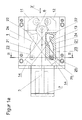
- FIG. 1a is to remove a bezel 1, the three lunette arms 6, 11 and 12 are completely retracted in a housing formed by two housing shells 4 and 5 to release the loading and unloading of the bezel 1.
- the three lunette arms 6, 11 and 12 are drivingly connected to a displaceably mounted between the two housing shells 4 and 5 actuating piston 7 which extends in alignment with the longitudinal axis 3 of the bezel 1 and by the movement direction 3 'is predetermined.
- the two outer lunette arms 11 and 12 are connected by guideways to the central lunette arm 6 which is axially movable back and forth directly from the actuating piston 7.
- the actuating piston 7 When the actuating piston 7 is displaced in the direction of a workpiece 2 to be clamped, that is to say in the direction of movement 3 ', the actuating force of the actuating piston 7 is transmitted via the central steady arm 6 to the two outer lunette arms 11 and 12, which consequently are in operative connection with them ,
- the two outer lunette arms 11 and 12 extend crosswise or like a scissor to each other and are guided at the free ends 14 via sliding block 25 and stop pins 26 in the guide groove 21 so that the two outer lunette arms 11 and 12 adjusted synchronously during the feed movement of the central lunette arm 6 are.
- the free arranged inside the housing shells 4 and 5 ends of the two outer lunette arms 11 and 12 are inserted via a sliding block 25 in the respective guide groove 21, so that the free ends of the outer lunette arms 11 and 12 first complete the course of the guide groove 21 and once the end of the guide groove 21, so the end of the second portion 24 is reached, in the control cam 22, as will be explained in more detail, immerse.
- the first and second part section 23 and 24 of the guide groove 21 corresponds to the feed movement of the outer lunette arms 11 and 12
- the control cam 22 corresponds to the tension travel of the outer lunette arms 11 and 12.
- FIGS. 1a . 1b . 1c 3a and 5 it can be seen that the two sections 23, 24 of the guide groove 21 have a different sized sized distance to the longitudinal axis 3 of the bezel 1.
- the first subsection 23 extends parallel to the longitudinal axis 3 and is farther away from the latter than the second subsection 24.
- the second subsection 24 is inclined in the direction of the longitudinal axis 3, so that between the first subsection 23 and the second subsection 24 Guide groove 21 results in a curvature, a bend or an angled structure.
- the second subsection 24 merges into the control curve 22, which is angled in the direction of the second subsection 24 of the guide groove 21 and points essentially in the direction of the outside of the respective housing shell 4 or 5.
- the two sections 23 and 24 of the guide groove 21 and the control cam 24 connected thereto form in cross-section substantially the shape of a stylized L with curvature or angle.
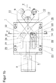
- FIG. 1b It is shown that the two outer lunette arms 11 and 12, after the free arranged in the housing shells 4 and 5 ends are retracted into the second portion 24 of the guide groove 21, are delivered in an arcuate manner in the direction of the workpiece 2 to be clamped. Accordingly, there is still no operative connection between the steady rest arms 6, 11 and 12 arranged in the loading and unloading zone of the workpiece 2, so that the three steady rest arms 6, 11 and 12 are spaced from the lateral surface of the workpiece 2 to be clamped. Nevertheless, the three lunette arms 6, 11 and 12 are moved out of the housing shells 4 and 5.
- the floating mounting of the stop pin 26 is achieved in that the substantially circular inner wall of the opening 28, which faces the control cam 22, a plane bearing surface 30 is worked.
- the stopper bolt 26 has a planar contact surface 27 extending in its longitudinal direction.
- the width of the planar contact surface 30 has a width which is greater than the width of the contact surface 27 of the stop pin 26, so that the stopper pin 26 is held slightly rotatable about its longitudinal axis in the opening 28. This floating bearing compensates for production-related inaccuracies.
- the two outer lunette arms 11 and 12 are completely retractable into the housing formed by the housing shells 4 and 5 in order to release the loading and unloading zone of the machine tool. Consequently, even large and heavy workpieces 2 can be easily and quickly held in the area of the steady rest 2, for example by means of a crane or the like, to subsequently the three lunette arms 6, 11 and 12 from the housing shells 4 and 5 in the direction of the workpiece to be clamped 2 deliver.
- the loading and unloading time is considerably reduced because the three lunette arms 6, 11 and 12 do not hinder the loading and unloading of the machine tool.
- the angle of inclination between the first partial section 23 extending parallel to the longitudinal axis 3 and the second partial section 24 adjoining it is between 10 ° and 25 °.
Abstract
Bei einer Lünette (1) zur Zentrierung eines rotationssymmetrischen Werkstückes (2) im Raum, bestehend aus: - zwei zueinander beabstandet angeordneten und fest miteinander verbundenen Gehäuseschalen (4, 5), - aus einem zwischen den beiden Gehäuseschalen (4, 5) angeordneten mittleren Lünettenarm (6), der mittels eines Betätigungskolbens (7) in axialer Bewegungsrichtung (3') auf das Werkstück (2) verschiebbar in denGehäuseschaltern (4, 5) gelagert ist, - zwei äußeren Lünettenarmen (11, 12), die mit dem mittleren Lünettenarm (6) trieblich verbunden sind, stollen die Lünettenarme (6, 11, 12) vollständig in das von den Gehäuseschalen (4, 5) gebildete Gehäuse einfahrbar sein. Dies ist dadurch erreicht, dass in jeder der Gehäuseschalen (4, 5) eine Führungsnut (21) und eine Steuerkurve (22) eingearbeitet ist, in die die in den Gehäuseschalen (4, 5) angeordneten freien Enden (14) der beiden äußeren Lünettenarme (11, 12) verschiebbar eingesetzt sind, dass die Führungsnut (21) aus einem ersten und zweiten Teilabschnitt (23, 24) gebildet ist, und dass der Abstand des ersten Teilabschnittes (23) zu der Längsachse (3) der Gehäuseschalen (4, 5) größer bemessen ist, als der Abstand des zweiten Teilabschnittes (24) der Führungsnut (21), der in die Steuerkurve (22) übergeht.In a steady rest (1) for centering a rotationally symmetrical workpiece (2) in space, consisting of: - two mutually spaced and firmly interconnected housing shells (4, 5), from a middle lunette arm (6) arranged between the two housing shells (4, 5) and slidably mounted in the housing switches (4, 5) by means of an actuating piston (7) in the axial direction of movement (3 ') on the workpiece (2), - Two outer Lünettenarmen (11, 12), which are drivingly connected to the middle Lünettenarm (6) cling the lunette arms (6, 11, 12) completely in the housing of the shells (4, 5) formed housing retractable. This is achieved in that in each of the housing shells (4, 5) a guide groove (21) and a control cam (22) is incorporated into which in the housing shells (4, 5) arranged free ends (14) of the two outer lunette arms (11, 12) are displaceably inserted, that the guide groove (21) of a first and second portion (23, 24) is formed, and that the distance of the first portion (23) to the longitudinal axis (3) of the housing shells (4, 5) is dimensioned larger than the distance of the second portion (24) of the guide groove (21), which merges into the control cam (22).
Description
Die Erfindung bezieht sich auf eine Lünette zur Zentrierung eines rotationssymmetrischen Werkstückes im Raum, nach dem Oberbegriff des Patentanspruches 1.The invention relates to a steady rest for centering a rotationally symmetrical workpiece in the room, according to the preamble of
Aus der
Solche zentrierbaren Lünetten kommen zum Einsatz, wenn Hochpräzisionswerkstücke zu fertigen sind, denn sobald Späne von dem Werkstück während der Bearbeitung abgetrennt sind, verändert sich dessen Eigengewicht, wodurch wiederum eine nachgeschaltete Zentrierung erforderlich ist, um entsprechende Bearbeitungsfehler auszugleichen.Such centerable steady rests are used when high-precision workpieces are to be manufactured, because as soon as chips are separated from the workpiece during machining, its own weight changes, which in turn requires downstream centering to compensate for corresponding processing errors.
Diese Lünetten haben sich für den erläuterten Einsatzzweck bewährt. Wenn jedoch Lünetten zur Verfügung zu stellen sind, um Werkstücke einzuspannen, an denen solche technischen Anforderungen nicht gestellt sind, da die abzustützenden Werkstücke gewisse fertigungsbedingte Bearbeitungsabweichungen aufweisen können, beispielsweise für die Massenproduktion von entsprechenden rotationssymmetrischen Werkstücken, dann ist es erforderlich, den Be- und Entladevorgang möglichst schnell zu bewerkstelligen. Da jedoch die Lünettenarme aus der von den Gehäuseschalen gebildeten Ebene in den Arbeitsbereich der Werkzeugmaschine überstehen, ist ein Abstand beim Be- und Entladen des Werkstückes zu den Lünettenarmen einzuhalten, um die Werkstücke an den Lünettenarmen vorbeizuführen. Insbesondere die beiden äußeren Lünettenarme behindern folglich den Be- und Entladevorgang.These steady rests have proven themselves for the purpose explained. However, if lunettes are to be made available in order to clamp workpieces where such technical requirements are not met, since the workpieces to be supported may have certain production-related machining deviations, For example, for the mass production of corresponding rotationally symmetrical workpieces, then it is necessary to accomplish the loading and unloading process as quickly as possible. However, since the lunette arms protrude from the plane formed by the housing shells in the working area of the machine tool, a distance during loading and unloading of the workpiece is to comply with the Lünettenarmen to pass the workpieces on the lunette arms. In particular, the two outer Lünettenarme thus hinder the loading and unloading.
Es ist daher Aufgabe der Erfindung, eine Lünette der eingangs genannten Gattung derart auszugestalten, dass die Lünettenarme vollständig in das von den Gehäuseschalen gebildete Gehäuse einfahrbar sind, um die Be- und Entladezone der Lünette freizugeben und dass gleichzeitig sowohl der Hubweg als auch die Bauraumgröße der Lünette unverändert beibehalten werden kann.It is therefore an object of the invention to design a bezel of the type mentioned in such a way that the lunette arms are completely retractable into the housing formed by the housing shells to release the loading and unloading of the bezel and that at the same time both the stroke and the space size of Bezel can be kept unchanged.
Diese Aufgaben sind erfindungsgemäß durch die Merkmale des kennzeichnenden Teils von Patentanspruch 1 gelöst.These objects are achieved by the features of the characterizing part of
Weitere vorteilhafte Weiterbildungen der Erfindungen ergeben sich aus den Unteransprüchen.Further advantageous developments of the invention will become apparent from the dependent claims.
Dadurch, dass unmittelbar in die beiden Gehäuseschalen eine Führungsnut eingearbeitet ist, die aus zwei Teilabschnitten besteht, deren Abstand zu der Längsachse der Lünette unterschiedlich groß bemessen ist, können die Lünettenarme vollständig in die Gehäuseschalen eingefahren werden, um aus dem Arbeitsbereich bzw. der Be- und Entladezone der Werkzeugmaschine zu gelangen. Die beiden miteinander verbundenen Teilabschnitte der Führungsnut sind dabei in den Gehäuseschalen derart ausgerichtet, dass der erste Teilabschnitt näher zu der Längsachse der Gehäuseschalen verläuft als der zweite Teilabschnitt der Führungsnut. Die beiden Teilabschnitte der Führungsnut sind miteinander verbunden und der erste Teilabschnitt der Führungsnut liegt weiter beabstandet zu dem Be- und Entladebereich, in das das Werkstück gelangt.The fact that a guide groove is incorporated directly into the two housing shells, which consists of two sections whose distance from the longitudinal axis of the bezel is dimensioned differently large, the lunette arms can be completely retracted into the housing shells to work from the field or the Be and unloading zone of the machine tool to get. The two interconnected subsections of the guide groove are aligned in the housing shells such that the first subsection is closer to the longitudinal axis of the housing shells than the second subsection of the guide groove. The two sections of the guide groove are connected to each other and the first section of the guide groove is further spaced from the loading and unloading, in which the workpiece passes.
Zudem sind die beiden Teilabschnitte der Führungsnut bogenförmig oder winklig zueinander ausgerichtet, so dass die beiden äußeren Lünettenarme beim Einfahren in die Gehäuseschalen einen entsprechenden Bewegungskurvenverlauf einnehmen und dann vollständig in die Gehäuseschalen eintauchen.In addition, the two sections of the guide groove arcuate or angularly aligned with each other, so that the two outer lunette arms when retracting into the housing shells take a corresponding curve of movement and then completely immerse in the housing shells.
Durch diese konstruktiven Maßnahmen ist vorteilhafterweise erreicht, dass der Bauraum der Lünette unverändert beibehalten werden kann, ohne dass die Lünette zu vergrößern ist, und dass auch der Hubweg, den die drei Lünettenarme zurücklegen können, identisch mit dem Hubweg und der Bauraumgröße von Lünetten ist, die die entsprechenden konstruktiven Ausgestaltungen der Führungsnut nicht aufweisen.By this constructive measures is advantageously achieved that the space of the bezel can be maintained unchanged without the bezel is to increase, and that the stroke, the three lunette arms can cover, is identical to the stroke and the space size of lunettes, which do not have the corresponding constructive embodiments of the guide groove.
Da bei der Fertigung der Gehäuseschalen und insbesondere der notwendigen Führungsnuten und Steuerkurven Herstellungsfehlertoleranzen auftreten, ist es äußerst zweckmäßig, wenn die im Inneren der Gehäuseschalen angeordneten freien Ende der beiden äußeren Lünettenarme mit einem Kulissenstein versehen sind, der in der Führungsnut verläuft und durch den die freien Ende der äußeren Lünettenarme in der jeweiligen Führungsnut verschiebbar gelagert sind. Sobald jedoch die Zustellbewegung der Lünettenarme beendet ist, also der erste und zweite Teilabschnitt der Führungsnut von dem Kulissenstein der äußeren Lünettenarme durchlaufen ist, ist eine Spannbewegung der äußeren Lünettenarme auf das einzuspannende Werkstück notwendig. Diese Spannbewegung ist durch die von dem zweiten Teilabschnitt abgewinkelten Steuerkurve erreicht, die in den zweiten Teilabschnitt der Führungsnut einmündet. Um die vorhandenen Herstellungsfehler auszugleichen, ist vorteilhafterweise an dem Kulissenstein ein Anschlagsbolzen schwimmend gelagert.Since manufacturing error tolerances occur in the production of the housing shells and in particular the necessary guide grooves and cams, it is extremely useful if the arranged inside the housing shells free end of the two outer lunette arms are provided with a sliding block, which runs in the guide and through which the free End of the outer lunette arms are slidably mounted in the respective guide groove. However, as soon as the feed movement of the lunette arms is completed, so the first and second section of the guide groove is traversed by the sliding block of the outer lunette arms, a clamping movement of the outer lunette arms on the workpiece to be clamped is necessary. This clamping movement is achieved by the angled from the second section control cam, which opens into the second section of the guide groove. To compensate for the existing manufacturing errors, a stop pin is advantageously mounted floating on the sliding block.
Die schwimmende Lagerung des Anschlagsbolzens an dem Kulissenstein ist dadurch erreicht, dass in den Kulissenstein eine Öffnung eingearbeitet ist und dass der Anschlagsbolzen eine plan ausgestaltete Anlagefläche aufweist. Ein vorgegebener Winkelbereich der Innenwand der Öffnung weist eine plane Kontur auf, die geringfügig größer bemessen ist als die Breite der Anlagefläche des Anschlagsbolzens. Folglich ist der Anschlagsbolzen in der Öffnung um seine eigene Längsachse geringfügig verdrehbar. Sollten daher gewisse Herstellungsfehler auftreten, können diese durch die Verdrehbarkeit des Anschlagsbolzens ausgeglichen werden, denn dieser legt sich mit seiner Anlagefläche an die dieser zugewandten Flanke der Steuerkurve an und gleitet während der Spannbewegung der Lünettenarme an dieser entlang. Durch die konstruktive Ausgestaltung des Anschlagsbolzens ist zudem erreicht, dass erhebliche Spannkräfte zwischen den Lünettenarmen, dem Anschlagsbolzen und den Gehäuseschalen übertragen werden können, denn die Anlagefläche des Anschlagsbolzen kann entsprechend hoch dimensionierte Druckkräfte aufnehmen und weiterleiten.The floating bearing of the stop bolt on the sliding block is achieved in that an opening is incorporated in the sliding block and that the stop pin has a plan designed contact surface. A predetermined angular range of the inner wall of the opening has a planar contour, which is dimensioned slightly larger than the width of the contact surface of the stop pin. Consequently, the stop pin is slightly rotatable in the opening about its own longitudinal axis. Therefore, if certain manufacturing errors occur, they can be compensated by the rotatability of the stop pin, because this is laying with its contact surface on the side facing this edge of the control cam and slides during the clamping movement of the lunette arms along this. Due to the structural design of the stop bolt is also achieved that considerable clamping forces between the steady rest, the stopper pin and the housing shells can be transmitted, because the contact surface of the stop pin can accommodate and forward correspondingly high-pressure forces.
Es ist jedoch auch denkbar, dass an dem Kulissenstein eine verdrehbare Rolle angebracht ist, die entlang der Flanke der Steuerkurve verfahrbar ist, um die Spannbewegungen der äußeren Lünettenarme zu erreichen.However, it is also conceivable that a rotatable roller is mounted on the sliding block, which is movable along the edge of the cam to achieve the clamping movements of the outer lunette arms.
In der Zeichnung ist ein erfindungsgemäßes Ausführungsbeispiel einer Lünette dargestellt, das nachfolgend näher erläutert ist. Im Einzelnen zeigt:
- Figur 1a
- eine Lünette mit zwei äußeren kreuzweise angeordneten Lünettenarmen und einem entlang der Längsachse der Lünette verschiebbar zwischen zwei Gehäuseschalen angeordneten mittleren Lünettenarm, der über einen Knotenpunkt der beiden äußeren Lünettenarme mit diesen in trieblicher Wirkverbindung steht, in Seitenansicht und im eingefahrenen Zustand der Lünettenarme,
- Figur 1b
- die Lünette gemäß
Figur 1a , im ausgefahrenen Zustand der Lünettenarme, unmittelbar bevor diese in Wirkkontakt mit einem einzuspannenden Werkstück treten, - Figur 1c
- die Lünette gemäß
Figur 1a , im Spannzustand, Figur 2- die Lünette gemäß
Figur 1a , entlang der Schnittlinie II-II, - Figur 3a
- eine Explosionsdarstellung der Lünette gemäß
Figur 1a , - Figur 3b
- ein vergrößerter Ausschnitt der Lünette, gemäß
Figur 1c , im Bereich IIIb, mit einem Kulissenstein, der an den äußeren Lünettenarmen befestigt ist und in den ein Anschlagsbolzen mit einer planen Anlagefläche eingesetzt ist, - Figur 3c
- die Lünette gemäß
Figur 3b mit einer an dem Kulissenstein angebrachten Rolle zur Abstützung der Spannbewegung der äußeren Lünettenarme, Figur 4- die Lünette gemäß
Figur 1c , entlang der Schnittlinie IV-IV und Figur 5- eine der Gehäuseschalen der Lünette gemäß
Figur 1a .
- FIG. 1a
- a bezel with two outer crosswise arranged Lünettenarmen and along the longitudinal axis of the bezel slidably disposed between two housing shells middle lunette, which is in operative connection via a junction of the two outer lunette arms with these in side view and in the retracted state of the lunette arms,
- FIG. 1b
- the bezel according to
FIG. 1a , in the extended state of the lunette arms, immediately before they come into operative contact with a workpiece to be clamped, - Figure 1c
- the bezel according to
FIG. 1a in the state of tension, - FIG. 2
- the bezel according to
FIG. 1a , along the section line II-II, - FIG. 3a
- an exploded view of the bezel according to
FIG. 1a . - FIG. 3b
- an enlarged section of the bezel, according to
Figure 1c , in the area IIIb, with a sliding block, which is attached to the outer Lünettenarmen and in which a stop pin is inserted with a flat contact surface, - Figure 3c
- the bezel according to
FIG. 3b with a roller attached to the sliding block for supporting the tensioning movement of the outer lunette arms, - FIG. 4
- the bezel according to
Figure 1c , along the section line IV-IV and - FIG. 5
- one of the housing shells of the bezel according to
FIG. 1a ,
In
In jede der beiden Gehäuseschalen 4 und 5 ist dabei eine aus zwei Teilabschnitten 23, 24 bestehende Führungsnut 21 sowie eine in die Führungsnut 21 einmündende Steuerkurve 22 eingearbeitet. Die Führungsnuten 21 und die Steuerkurven 22 der beiden Gehäuseschalen 4 und 5 sind dabei spiegelbildlich zueinander ausgerichtet.In each of the two
Die drei Lünettenarme 6, 11 und 12 sind trieblich mit einem zwischen den beiden Gehäuseschalen 4 und 5 verschiebbar gelagerten Betätigungskolben 7 verbunden, der fluchtend zu der Längsachse 3 der Lünette 1 verläuft und durch den die Bewegungsrichtung 3' vorgegeben ist. Die zwei äußeren Lünettenarme 11 und 12 sind durch Führungsbahnen mit dem mittleren Lünettenarm 6 verbunden, der unmittelbar von dem Betätigungskolben 7 axial hin- und her verfahrbar ist. Wenn der Betätigungskolben 7 in Richtung eines einzuspannenden Werkstückes 2, also in Bewegungsrichtung 3', verschoben ist, dann wird die Betätigungskraft des Betätigungskolbens 7 über den mittleren Lünettenarm 6 an die beiden äußeren Lünettenarme 11 und 12 übertragen, die folglich mit diesen in trieblicher Wirkverbindung stehen. Die beiden äußeren Lünettenarme 11 und 12 verlaufen kreuzweise oder scherenartig zueinander und sind an den freien Enden 14 über Kulissenstein 25 bzw. Anschlagsbolzen 26 in der Führungsnut 21 geführt, so dass bei der Zustellbewegung des mittleren Lünettenarmes 6 die beiden äußeren Lünettenarme 11 und 12 synchron verstellt sind.The three
Die freien im Inneren der Gehäuseschalen 4 und 5 angeordneten Enden der beiden äußeren Lünettenarme 11 und 12 sind über einen Kulissenstein 25 in der jeweiligen Führungsnut 21 eingesetzt, so dass die freien Enden der äußeren Lünettenarme 11 und 12 zunächst den Verlauf der Führungsnut 21 vollziehen und sobald das Ende der Führungsnut 21, also das Ende des zweiten Teilabschnittes 24, erreicht ist, in die Steuerkurve 22, wie dies nachfolgend noch näher erläutert ist, eintauchen. Dabei entspricht der erste und zweite Teilabschnitt 23 und 24 der Führungsnut 21 der Zustellbewegung der äußeren Lünettenarme 11 und 12 und die Steuerkurve 22 dem Spannweg der äußeren Lünettenarme 11 und 12.The free arranged inside the
Insbesondere den
In
In
Insbesondere aus den
Die schwimmende Lagerung des Anschlagsbolzens 26 ist dadurch erreicht, dass die im Wesentlichen runde Innenwand der Öffnung 28, der der Steuerkurve 22 zugewandt ist, eine plane Anlagefläche 30 angearbeitet ist. Der Anschlagsbolzen 26 weist eine in dessen Längsrichtung sich erstreckende plane Anlagefläche 27 auf. Die Breite der planen Anlagefläche 30 weist eine Breite auf, die größer bemessen ist, als die Breite der Anlagefläche 27 des Anschlagsbolzens 26, so dass der Anschlagsbolzen 26 geringfügig um seine Längsachse verdrehbar in der Öffnung 28 gehalten ist. Diese schwimmende Lagerung dient als Ausgleich für herstellungsbedingte Ungenauigkeiten.The floating mounting of the
Sobald gemäß
Aufgrund der vollflächigen Anlage des Anschlagsbolzens 26 an der Flanke der Steuerkurve 22 können erhebliche Spannkräfte zwischen dem Betätigungskolben 7, den Lünettenarmen 11 und 12 und dem Werkstück 2 übertragen werden.Due to the full-surface contact of the
Gemäß
Aufgrund der bogen- oder winkelförmigen Ausgestaltung der Führungsnut 21 ist erreicht, dass die beiden äußeren Lünettenarme 11 und 12 vollständig in das von den Gehäuseschalen 4 und 5 gebildete Gehäuse einfahrbar sind, um die Be- und Entladezone der Werkzeugmaschine freizugeben. Folglich können auch groß bemessene und schwere Werkstücke 2 unkompliziert und schnell im Bereich der Lünette 2, beispielsweise mittels eines Krans oder dgl., gehalten werden, um anschließend die drei Lünettenarme 6, 11 und 12 aus den Gehäuseschalen 4 und 5 in Richtung des einzuspannenden Werkstückes 2 zuzustellen. Die Be- und Entladezeit wird dadurch erheblich reduziert, da die drei Lünettenarme 6, 11 und 12 die Be- und Entladung der Werkzeugmaschine nicht behindern.Due to the arcuate or angular configuration of the
Der Neigungswinkel zwischen dem ersten parallel zu der Längsachse 3 verlaufenden Teilabschnitt 23 und dem sich daran anschließenden zweiten Teilabschnitt 24 liegt zwischen 10° und 25°.The angle of inclination between the first
Claims (11)
bestehend aus:
dass in jeder der Gehäuseschalen (4, 5) eine Führungsnut (21) und eine Steuerkurve (22) eingearbeitet ist, in die die in den Gehäuseschalen (4, 5) angeordneten freien Enden (14) der beiden äußeren Lünettenarme (11, 12) verschiebbar eingesetzt sind, dass die Führungsnut (21) aus einem ersten und zweiten Teilabschnitt (23, 24) gebildet ist, und dass der Abstand des ersten Teilabschnittes (23) zu der Längsachse (3) der Gehäuseschalen (4, 5) größer bemessen ist, als der Abstand des zweiten Teilabschnittes (24) der Führungsnut (21), der in die Steuerkurve (22) übergeht.Steady rest (1) for centering a rotationally symmetrical workpiece (2) in space,
consisting of:
that in each of the housing shells (4, 5) a guide groove (21) and a control cam (22) is incorporated, in which in the housing shells (4, 5) arranged free ends (14) of the two outer lunette arms (11, 12) movable inserted, that the guide groove (21) of a first and second portion (23, 24) is formed, and that the distance of the first portion (23) to the longitudinal axis (3) of the housing shells (4, 5) is sized larger, as the distance of the second section (24) of the guide groove (21), which merges into the control cam (22).
dadurch gekennzeichnet,
dass der erste und der zweite Teilabschnitt (23, 24) im Übergangsbereich eine gekrümmte, bogenförmige oder winklige Innenkontur aufweisen.Bezel according to claim 1,
characterized,
that the first and the second partial section (23, 24) in the transition region have a curved, arc-shaped or angular inner contour.
dadurch gekennzeichnet,
dass an dem im Inneren der Gehäuseschalen (4, 5) verlaufenden äußeren Lünettenarmen (11, 12) jeweils ein Kulissenstein (25) angebracht ist, dass an den Kulissenstein (25) ein Anschlagsbolzen (26) befestigt ist, der über eine schwimmend ausgestaltete Lagerung mit dem Kulissenstein (25) verbunden ist.Bezel according to claim 1 or 2,
characterized,
that on the inside of the housing shells (4, 5) extending outer lunette arms (11, 12) each a sliding block (25) is mounted, that on the sliding block (25) a stop pin (26) is fixed, which has a floating designed storage is connected to the sliding block (25).
dadurch gekennzeichnet,
dass der Kulissenstein (25) fest mit dem jeweiligen Lünettenarm (11, 12) verbunden ist und dass der Anschlagsbolzen (26) aus der von dem Kulissenstein (25) gebildeten Ebene übersteht.Bezel according to claim 3,
characterized,
that the sliding block (25) is fixedly connected to the respective lunette arm (11, 12) and that the stop bolt (26) protrudes from the plane formed by the sliding block (25).
dadurch gekennzeichnet,
dass an dem Anschlagsbolzen (26) eine plane Anlagefläche (27) abgearbeitet ist, durch die der Anschlagsbolzen (26) in einer in dem Kulissenstein (25) eingearbeiteten Öffnung (28) um die eigene Längsachse geringfügig verdrehbar gelagert ist und dass die Anlagefläche (27) des Anschlagsbolzens eine in Bewegungsrichtung (3') weisende Flanke der Steuerkurve (22) zugewandt ist.Bezel according to claim 3 or 4,
characterized,
that on the stop pin (26) a planar bearing surface (27) is processed, by the stopper pin (26) in an in the sliding block (25) incorporated opening (28) is mounted slightly rotatable about its own longitudinal axis and that the contact surface (27 ) of the stop pin facing in the direction of movement (3 ') edge of the control cam (22) faces.
dadurch gekennzeichnet,
dass ein Teilbereich der Öffnung (28) eine plane Anlagefläche (30) aufweist, die senkrecht zu der Bewegungsrichtung (3') ausgerichtet und der Steuerkurve (22) zugewandt ist, dass die Anlagefläche (27) des Anschlagsbolzens (26) an der Anladefläche (30) der Öffnung (28) anliegt und dass die Breite der Anlagefläche (30) geringfügig größer bemessen ist als die Anschlagsfläche (27) des Anschlagsbolzen (26).Bezel according to claim 5,
characterized,
that a partial area of the opening (28) has a plane abutment surface (30), aligned perpendicular to the traveling direction (3 ') and the control cam (22) faces, that the contact surface (27) of the stop pin (26) on the Anladefläche ( 30) of the opening (28) and that the width of the contact surface (30) is dimensioned slightly larger than the abutment surface (27) of the stop pin (26).
dadurch gekennzeichnet,
dass die Anlagefläche (27) des Anschlagsbolzens (26) im Spannzustand der Lünettenarme (6, 11, 12) an der der Führungsnut (21) zugewandten Flanke der Steuerkurve (22) anliegt und entlang dieser während der Spannbewegung der Lünettenarme (6, 11, 12) geführt ist.Bezel according to claim 5 or 6,
characterized,
in that the contact surface (27) of the stop pin (26) rests against the flank of the control cam (22) facing the guide groove (21) in the clamping state of the steady rest arms (21, 12) and along this during the tensioning movement of the steady rest arms (6, 11, 12). 12) is guided.
dadurch gekennzeichnet,
dass an dem Kulissenstein (25) eine Rolle (29) drehbar angelenkt ist, die aus der von dem Kulissenstein (25) gebildeten Ebene übersteht.Bezel according to claim 3,
characterized,
that on the sliding block (25) has a roller (29) is rotatably articulated, which protrudes from the of the sliding block (25) formed plane.
dadurch gekennzeichnet,
dass die Rolle (29) entlang der von der Flanke (22') der Steuerkurve (22) gebildeten Ebene während der Spannzustellung der Lünettenarme (6, 11, 12) geführt ist.Bezel according to claim 8,
characterized,
in that the roller (29) is guided along the plane formed by the flank (22 ') of the control cam (22) during the tensioning of the lunette arms (6, 11, 12).
dadurch gekennzeichnet,
dass der erste Teilabschnitt (23) der Führungsnut (21) parallel zu der Längsachse (3) der Gehäuseschalen (4, 5) ausgerichtet ist und dass der zweite Teilabschnitt (24) der Führungsnut in Richtung der Längsachse (3) der Gehäuseschalen (4, 5) geneigt ist.Lunette according to one of the preceding claims,
characterized,
in that the first subsection (23) of the guide groove (21) is aligned parallel to the longitudinal axis (3) of the housing shells (4, 5) and that the second subsection (24) of the guide groove in the direction of the longitudinal axis (3) of the housing shells (4, 5) is inclined.
dadurch gekennzeichnet,
dass der Neigungswinkel zwischen dem ersten und dem zweiten Teilabschnitt (23, 24) der Führungsnut (21) in einem Winkelbereich von 10° bis 25° ausgebildet ist.Bezel according to claim 10,
characterized,
in that the angle of inclination between the first and the second partial section (23, 24) of the guide groove (21) is formed in an angular range of 10 ° to 25 °.
Priority Applications (1)
| Application Number | Priority Date | Filing Date | Title |
|---|---|---|---|
| EP13184360.9A EP2848359B1 (en) | 2013-09-13 | 2013-09-13 | Stationary support |
Applications Claiming Priority (1)
| Application Number | Priority Date | Filing Date | Title |
|---|---|---|---|
| EP13184360.9A EP2848359B1 (en) | 2013-09-13 | 2013-09-13 | Stationary support |
Publications (2)
| Publication Number | Publication Date |
|---|---|
| EP2848359A1 true EP2848359A1 (en) | 2015-03-18 |
| EP2848359B1 EP2848359B1 (en) | 2016-11-09 |
Family
ID=49209245
Family Applications (1)
| Application Number | Title | Priority Date | Filing Date |
|---|---|---|---|
| EP13184360.9A Active EP2848359B1 (en) | 2013-09-13 | 2013-09-13 | Stationary support |
Country Status (1)
| Country | Link |
|---|---|
| EP (1) | EP2848359B1 (en) |
Cited By (4)
| Publication number | Priority date | Publication date | Assignee | Title |
|---|---|---|---|---|
| EP3093102A1 (en) | 2015-05-12 | 2016-11-16 | SMW-Autoblok Spannsysteme GmbH | Stationary support |
| EP3093103A1 (en) | 2015-05-12 | 2016-11-16 | SMW-Autoblok Spannsysteme GmbH | Stationary support |
| WO2017042031A1 (en) * | 2015-09-10 | 2017-03-16 | Walter Maschinenbau Gmbh | Actuating device for a steady rest |
| CN109654981A (en) * | 2019-02-21 | 2019-04-19 | 银川特种轴承有限公司 | Round piece external diameter circularity detection device |
Families Citing this family (1)
| Publication number | Priority date | Publication date | Assignee | Title |
|---|---|---|---|---|
| DE102016215913A1 (en) | 2016-08-24 | 2018-03-01 | Volkswagen Aktiengesellschaft | jig |
Citations (4)
| Publication number | Priority date | Publication date | Assignee | Title |
|---|---|---|---|---|
| US5058468A (en) * | 1990-09-19 | 1991-10-22 | Arobotech Systems, Inc. | Remote gage steady rest head |
| DE19950706A1 (en) * | 1999-10-21 | 2001-05-10 | Smw Autoblok Spannsysteme Gmbh | Clamping device to hold workpiece, with holding members supported in separate intermediate member |
| EP2505302A1 (en) * | 2011-03-29 | 2012-10-03 | SMW-AUTOBLOK Spannsysteme GmbH | Stationary support |
| EP2505303A1 (en) | 2011-03-29 | 2012-10-03 | SMW-AUTOBLOK Spannsysteme GmbH | Stationary support |
-
2013
- 2013-09-13 EP EP13184360.9A patent/EP2848359B1/en active Active
Patent Citations (4)
| Publication number | Priority date | Publication date | Assignee | Title |
|---|---|---|---|---|
| US5058468A (en) * | 1990-09-19 | 1991-10-22 | Arobotech Systems, Inc. | Remote gage steady rest head |
| DE19950706A1 (en) * | 1999-10-21 | 2001-05-10 | Smw Autoblok Spannsysteme Gmbh | Clamping device to hold workpiece, with holding members supported in separate intermediate member |
| EP2505302A1 (en) * | 2011-03-29 | 2012-10-03 | SMW-AUTOBLOK Spannsysteme GmbH | Stationary support |
| EP2505303A1 (en) | 2011-03-29 | 2012-10-03 | SMW-AUTOBLOK Spannsysteme GmbH | Stationary support |
Cited By (9)
| Publication number | Priority date | Publication date | Assignee | Title |
|---|---|---|---|---|
| EP3093102A1 (en) | 2015-05-12 | 2016-11-16 | SMW-Autoblok Spannsysteme GmbH | Stationary support |
| EP3093103A1 (en) | 2015-05-12 | 2016-11-16 | SMW-Autoblok Spannsysteme GmbH | Stationary support |
| US9937596B2 (en) | 2015-05-12 | 2018-04-10 | Smw-Autoblok Spannsysteme Gmbh | Steady rest |
| US9969039B2 (en) | 2015-05-12 | 2018-05-15 | Smw-Autoblok Spannsysteme Gmbh | Steady rest |
| WO2017042031A1 (en) * | 2015-09-10 | 2017-03-16 | Walter Maschinenbau Gmbh | Actuating device for a steady rest |
| AU2016318561B2 (en) * | 2015-09-10 | 2019-06-27 | Walter Maschinenbau Gmbh | Actuating device for a steady rest |
| US10357858B2 (en) | 2015-09-10 | 2019-07-23 | Walter Maschinenbau Gmbh | Actuating device for a steady rest |
| CN109654981A (en) * | 2019-02-21 | 2019-04-19 | 银川特种轴承有限公司 | Round piece external diameter circularity detection device |
| CN109654981B (en) * | 2019-02-21 | 2023-12-26 | 银川特种轴承有限公司 | Circular workpiece outer diameter roundness detection device |
Also Published As
| Publication number | Publication date |
|---|---|
| EP2848359B1 (en) | 2016-11-09 |
Similar Documents
| Publication | Publication Date | Title |
|---|---|---|
| EP2618961B1 (en) | Method and device for machining elongate workpieces that are not rotationally symmetrical in the form of turbine blades | |
| EP2848359B1 (en) | Stationary support | |
| EP2505302B1 (en) | Stationary support | |
| EP2566644B1 (en) | Centric clamping device | |
| EP3093102B1 (en) | Stationary support | |
| EP2505303B1 (en) | Stationary support | |
| DE102015212541A1 (en) | processing device | |
| CH657567A5 (en) | REVOLVER PUNCH. | |
| DE1146724B (en) | Chucks for machine tools | |
| DE2359918A1 (en) | DEVICE FOR PUNCHING AND TRANSFERRING WORK PIECES TO A DOWNSTREAM TREATMENT DEVICE | |
| DE102008007233B4 (en) | grinding machine | |
| EP3093103B1 (en) | Stationary support | |
| EP3515626B1 (en) | Machine tool and method for machining planar workpieces | |
| DE2138415A1 (en) | Tool gripping and guiding device for punches or similar machines | |
| DE19722308C1 (en) | Static cylinder machine for crankshafts | |
| DE2530813A1 (en) | MACHINING DEVICE FOR PISTON | |
| EP2823934A1 (en) | Device for finishing a peripheral area of a workpiece and method for operating the device | |
| DE102015104058B3 (en) | Centric clamping device | |
| DE102013213176A1 (en) | Device for clamping a workpiece | |
| EP1428612A1 (en) | Device and method for the angular positioning of eccentric workpieces such as crankshafts, by means of indexing jaws on a steady rest | |
| DE1800871B2 (en) | Honing or grinding device for simultaneous machining of a workpiece with a central bore, two end faces and a characteristic circle (e.g. pitch circle or outer surface), such as a gear wheel or a bearing race | |
| DE202015003445U1 (en) | tool unit | |
| WO2017050584A1 (en) | Multi-tool for processing workpieces, in particular metal sheets | |
| EP2103367A1 (en) | Clamping device for objects e.g. for workpieces to be processed | |
| EP3664945A1 (en) | Bending machine for bending rod-shaped or tubular workpieces |
Legal Events
| Date | Code | Title | Description |
|---|---|---|---|
| PUAI | Public reference made under article 153(3) epc to a published international application that has entered the european phase |
Free format text: ORIGINAL CODE: 0009012 |
|
| 17P | Request for examination filed |
Effective date: 20140930 |
|
| AK | Designated contracting states |
Kind code of ref document: A1 Designated state(s): AL AT BE BG CH CY CZ DE DK EE ES FI FR GB GR HR HU IE IS IT LI LT LU LV MC MK MT NL NO PL PT RO RS SE SI SK SM TR |
|
| AX | Request for extension of the european patent |
Extension state: BA ME |
|
| GRAP | Despatch of communication of intention to grant a patent |
Free format text: ORIGINAL CODE: EPIDOSNIGR1 |
|
| INTG | Intention to grant announced |
Effective date: 20160613 |
|
| GRAS | Grant fee paid |
Free format text: ORIGINAL CODE: EPIDOSNIGR3 |
|
| GRAA | (expected) grant |
Free format text: ORIGINAL CODE: 0009210 |
|
| AK | Designated contracting states |
Kind code of ref document: B1 Designated state(s): AL AT BE BG CH CY CZ DE DK EE ES FI FR GB GR HR HU IE IS IT LI LT LU LV MC MK MT NL NO PL PT RO RS SE SI SK SM TR |
|
| REG | Reference to a national code |
Ref country code: GB Ref legal event code: FG4D Free format text: NOT ENGLISH |
|
| REG | Reference to a national code |
Ref country code: AT Ref legal event code: REF Ref document number: 843441 Country of ref document: AT Kind code of ref document: T Effective date: 20161115 Ref country code: CH Ref legal event code: EP |
|
| REG | Reference to a national code |
Ref country code: IE Ref legal event code: FG4D Free format text: LANGUAGE OF EP DOCUMENT: GERMAN |
|
| REG | Reference to a national code |
Ref country code: DE Ref legal event code: R096 Ref document number: 502013005275 Country of ref document: DE |
|
| PG25 | Lapsed in a contracting state [announced via postgrant information from national office to epo] |
Ref country code: LV Free format text: LAPSE BECAUSE OF FAILURE TO SUBMIT A TRANSLATION OF THE DESCRIPTION OR TO PAY THE FEE WITHIN THE PRESCRIBED TIME-LIMIT Effective date: 20161109 |
|
| REG | Reference to a national code |
Ref country code: LT Ref legal event code: MG4D |
|
| REG | Reference to a national code |
Ref country code: NL Ref legal event code: MP Effective date: 20161109 |
|
| PG25 | Lapsed in a contracting state [announced via postgrant information from national office to epo] |
Ref country code: GR Free format text: LAPSE BECAUSE OF FAILURE TO SUBMIT A TRANSLATION OF THE DESCRIPTION OR TO PAY THE FEE WITHIN THE PRESCRIBED TIME-LIMIT Effective date: 20170210 Ref country code: NL Free format text: LAPSE BECAUSE OF FAILURE TO SUBMIT A TRANSLATION OF THE DESCRIPTION OR TO PAY THE FEE WITHIN THE PRESCRIBED TIME-LIMIT Effective date: 20161109 Ref country code: SE Free format text: LAPSE BECAUSE OF FAILURE TO SUBMIT A TRANSLATION OF THE DESCRIPTION OR TO PAY THE FEE WITHIN THE PRESCRIBED TIME-LIMIT Effective date: 20161109 Ref country code: NO Free format text: LAPSE BECAUSE OF FAILURE TO SUBMIT A TRANSLATION OF THE DESCRIPTION OR TO PAY THE FEE WITHIN THE PRESCRIBED TIME-LIMIT Effective date: 20170209 Ref country code: LT Free format text: LAPSE BECAUSE OF FAILURE TO SUBMIT A TRANSLATION OF THE DESCRIPTION OR TO PAY THE FEE WITHIN THE PRESCRIBED TIME-LIMIT Effective date: 20161109 |
|
| PG25 | Lapsed in a contracting state [announced via postgrant information from national office to epo] |
Ref country code: ES Free format text: LAPSE BECAUSE OF FAILURE TO SUBMIT A TRANSLATION OF THE DESCRIPTION OR TO PAY THE FEE WITHIN THE PRESCRIBED TIME-LIMIT Effective date: 20161109 Ref country code: FI Free format text: LAPSE BECAUSE OF FAILURE TO SUBMIT A TRANSLATION OF THE DESCRIPTION OR TO PAY THE FEE WITHIN THE PRESCRIBED TIME-LIMIT Effective date: 20161109 Ref country code: PT Free format text: LAPSE BECAUSE OF FAILURE TO SUBMIT A TRANSLATION OF THE DESCRIPTION OR TO PAY THE FEE WITHIN THE PRESCRIBED TIME-LIMIT Effective date: 20170309 Ref country code: HR Free format text: LAPSE BECAUSE OF FAILURE TO SUBMIT A TRANSLATION OF THE DESCRIPTION OR TO PAY THE FEE WITHIN THE PRESCRIBED TIME-LIMIT Effective date: 20161109 Ref country code: RS Free format text: LAPSE BECAUSE OF FAILURE TO SUBMIT A TRANSLATION OF THE DESCRIPTION OR TO PAY THE FEE WITHIN THE PRESCRIBED TIME-LIMIT Effective date: 20161109 Ref country code: IS Free format text: LAPSE BECAUSE OF FAILURE TO SUBMIT A TRANSLATION OF THE DESCRIPTION OR TO PAY THE FEE WITHIN THE PRESCRIBED TIME-LIMIT Effective date: 20170309 Ref country code: PL Free format text: LAPSE BECAUSE OF FAILURE TO SUBMIT A TRANSLATION OF THE DESCRIPTION OR TO PAY THE FEE WITHIN THE PRESCRIBED TIME-LIMIT Effective date: 20161109 |
|
| PG25 | Lapsed in a contracting state [announced via postgrant information from national office to epo] |
Ref country code: SK Free format text: LAPSE BECAUSE OF FAILURE TO SUBMIT A TRANSLATION OF THE DESCRIPTION OR TO PAY THE FEE WITHIN THE PRESCRIBED TIME-LIMIT Effective date: 20161109 Ref country code: RO Free format text: LAPSE BECAUSE OF FAILURE TO SUBMIT A TRANSLATION OF THE DESCRIPTION OR TO PAY THE FEE WITHIN THE PRESCRIBED TIME-LIMIT Effective date: 20161109 Ref country code: DK Free format text: LAPSE BECAUSE OF FAILURE TO SUBMIT A TRANSLATION OF THE DESCRIPTION OR TO PAY THE FEE WITHIN THE PRESCRIBED TIME-LIMIT Effective date: 20161109 Ref country code: CZ Free format text: LAPSE BECAUSE OF FAILURE TO SUBMIT A TRANSLATION OF THE DESCRIPTION OR TO PAY THE FEE WITHIN THE PRESCRIBED TIME-LIMIT Effective date: 20161109 Ref country code: EE Free format text: LAPSE BECAUSE OF FAILURE TO SUBMIT A TRANSLATION OF THE DESCRIPTION OR TO PAY THE FEE WITHIN THE PRESCRIBED TIME-LIMIT Effective date: 20161109 |
|
| REG | Reference to a national code |
Ref country code: DE Ref legal event code: R097 Ref document number: 502013005275 Country of ref document: DE |
|
| PG25 | Lapsed in a contracting state [announced via postgrant information from national office to epo] |
Ref country code: IT Free format text: LAPSE BECAUSE OF FAILURE TO SUBMIT A TRANSLATION OF THE DESCRIPTION OR TO PAY THE FEE WITHIN THE PRESCRIBED TIME-LIMIT Effective date: 20161109 Ref country code: SM Free format text: LAPSE BECAUSE OF FAILURE TO SUBMIT A TRANSLATION OF THE DESCRIPTION OR TO PAY THE FEE WITHIN THE PRESCRIBED TIME-LIMIT Effective date: 20161109 Ref country code: BG Free format text: LAPSE BECAUSE OF FAILURE TO SUBMIT A TRANSLATION OF THE DESCRIPTION OR TO PAY THE FEE WITHIN THE PRESCRIBED TIME-LIMIT Effective date: 20170209 |
|
| PLBE | No opposition filed within time limit |
Free format text: ORIGINAL CODE: 0009261 |
|
| STAA | Information on the status of an ep patent application or granted ep patent |
Free format text: STATUS: NO OPPOSITION FILED WITHIN TIME LIMIT |
|
| 26N | No opposition filed |
Effective date: 20170810 |
|
| PG25 | Lapsed in a contracting state [announced via postgrant information from national office to epo] |
Ref country code: SI Free format text: LAPSE BECAUSE OF FAILURE TO SUBMIT A TRANSLATION OF THE DESCRIPTION OR TO PAY THE FEE WITHIN THE PRESCRIBED TIME-LIMIT Effective date: 20161109 |
|
| REG | Reference to a national code |
Ref country code: CH Ref legal event code: PL |
|
| GBPC | Gb: european patent ceased through non-payment of renewal fee |
Effective date: 20170913 |
|
| PG25 | Lapsed in a contracting state [announced via postgrant information from national office to epo] |
Ref country code: MC Free format text: LAPSE BECAUSE OF FAILURE TO SUBMIT A TRANSLATION OF THE DESCRIPTION OR TO PAY THE FEE WITHIN THE PRESCRIBED TIME-LIMIT Effective date: 20161109 |
|
| REG | Reference to a national code |
Ref country code: IE Ref legal event code: MM4A |
|
| REG | Reference to a national code |
Ref country code: BE Ref legal event code: MM Effective date: 20170930 |
|
| PG25 | Lapsed in a contracting state [announced via postgrant information from national office to epo] |
Ref country code: LU Free format text: LAPSE BECAUSE OF NON-PAYMENT OF DUE FEES Effective date: 20170913 |
|
| REG | Reference to a national code |
Ref country code: FR Ref legal event code: ST Effective date: 20180531 |
|
| PG25 | Lapsed in a contracting state [announced via postgrant information from national office to epo] |
Ref country code: CH Free format text: LAPSE BECAUSE OF NON-PAYMENT OF DUE FEES Effective date: 20170930 Ref country code: GB Free format text: LAPSE BECAUSE OF NON-PAYMENT OF DUE FEES Effective date: 20170913 Ref country code: IE Free format text: LAPSE BECAUSE OF NON-PAYMENT OF DUE FEES Effective date: 20170913 Ref country code: LI Free format text: LAPSE BECAUSE OF NON-PAYMENT OF DUE FEES Effective date: 20170930 |
|
| PG25 | Lapsed in a contracting state [announced via postgrant information from national office to epo] |
Ref country code: FR Free format text: LAPSE BECAUSE OF NON-PAYMENT OF DUE FEES Effective date: 20171002 Ref country code: BE Free format text: LAPSE BECAUSE OF NON-PAYMENT OF DUE FEES Effective date: 20170930 |
|
| PG25 | Lapsed in a contracting state [announced via postgrant information from national office to epo] |
Ref country code: MT Free format text: LAPSE BECAUSE OF FAILURE TO SUBMIT A TRANSLATION OF THE DESCRIPTION OR TO PAY THE FEE WITHIN THE PRESCRIBED TIME-LIMIT Effective date: 20161109 |
|
| PG25 | Lapsed in a contracting state [announced via postgrant information from national office to epo] |
Ref country code: HU Free format text: LAPSE BECAUSE OF FAILURE TO SUBMIT A TRANSLATION OF THE DESCRIPTION OR TO PAY THE FEE WITHIN THE PRESCRIBED TIME-LIMIT; INVALID AB INITIO Effective date: 20130913 |
|
| PG25 | Lapsed in a contracting state [announced via postgrant information from national office to epo] |
Ref country code: CY Free format text: LAPSE BECAUSE OF FAILURE TO SUBMIT A TRANSLATION OF THE DESCRIPTION OR TO PAY THE FEE WITHIN THE PRESCRIBED TIME-LIMIT Effective date: 20161109 |
|
| REG | Reference to a national code |
Ref country code: AT Ref legal event code: MM01 Ref document number: 843441 Country of ref document: AT Kind code of ref document: T Effective date: 20180913 |
|
| PG25 | Lapsed in a contracting state [announced via postgrant information from national office to epo] |
Ref country code: MK Free format text: LAPSE BECAUSE OF FAILURE TO SUBMIT A TRANSLATION OF THE DESCRIPTION OR TO PAY THE FEE WITHIN THE PRESCRIBED TIME-LIMIT Effective date: 20161109 |
|
| PG25 | Lapsed in a contracting state [announced via postgrant information from national office to epo] |
Ref country code: AT Free format text: LAPSE BECAUSE OF NON-PAYMENT OF DUE FEES Effective date: 20180913 |
|
| PG25 | Lapsed in a contracting state [announced via postgrant information from national office to epo] |
Ref country code: TR Free format text: LAPSE BECAUSE OF FAILURE TO SUBMIT A TRANSLATION OF THE DESCRIPTION OR TO PAY THE FEE WITHIN THE PRESCRIBED TIME-LIMIT Effective date: 20161109 |
|
| PG25 | Lapsed in a contracting state [announced via postgrant information from national office to epo] |
Ref country code: AL Free format text: LAPSE BECAUSE OF FAILURE TO SUBMIT A TRANSLATION OF THE DESCRIPTION OR TO PAY THE FEE WITHIN THE PRESCRIBED TIME-LIMIT Effective date: 20161109 |
|
| REG | Reference to a national code |
Ref country code: DE Ref legal event code: R082 Ref document number: 502013005275 Country of ref document: DE Representative=s name: GEITZ PATENTANWAELTE PARTG MBB, DE Ref country code: DE Ref legal event code: R082 Ref document number: 502013005275 Country of ref document: DE Representative=s name: GEITZ TRUCKENMUELLER LUCHT CHRIST PATENTANWAEL, DE |
|
| P01 | Opt-out of the competence of the unified patent court (upc) registered |
Effective date: 20230527 |
|
| PGFP | Annual fee paid to national office [announced via postgrant information from national office to epo] |
Ref country code: DE Payment date: 20230919 Year of fee payment: 11 |